


CHAPTER 6
Removals and
Replacements
Chapter 6 REMOVALS AND REPLACEMENTS
6.1 REPLACEMENT OF THE CONSUMABLE (To n e r, Drum, Fuser Felt)
When the toner supply is low, a TONER LOW message will be displayed. Approximately 200 pages can still
be printed before the toner supply runs out completely and the toner cartridge must be replaced.
When the toner supply is completely depleted, TONER EMPTY appears in the display.
When you replace the toner cartridge, you have to replace the drum cartridge and the fuser felt as well.
Supplies are available by contacting your local samsung Business systems representative.
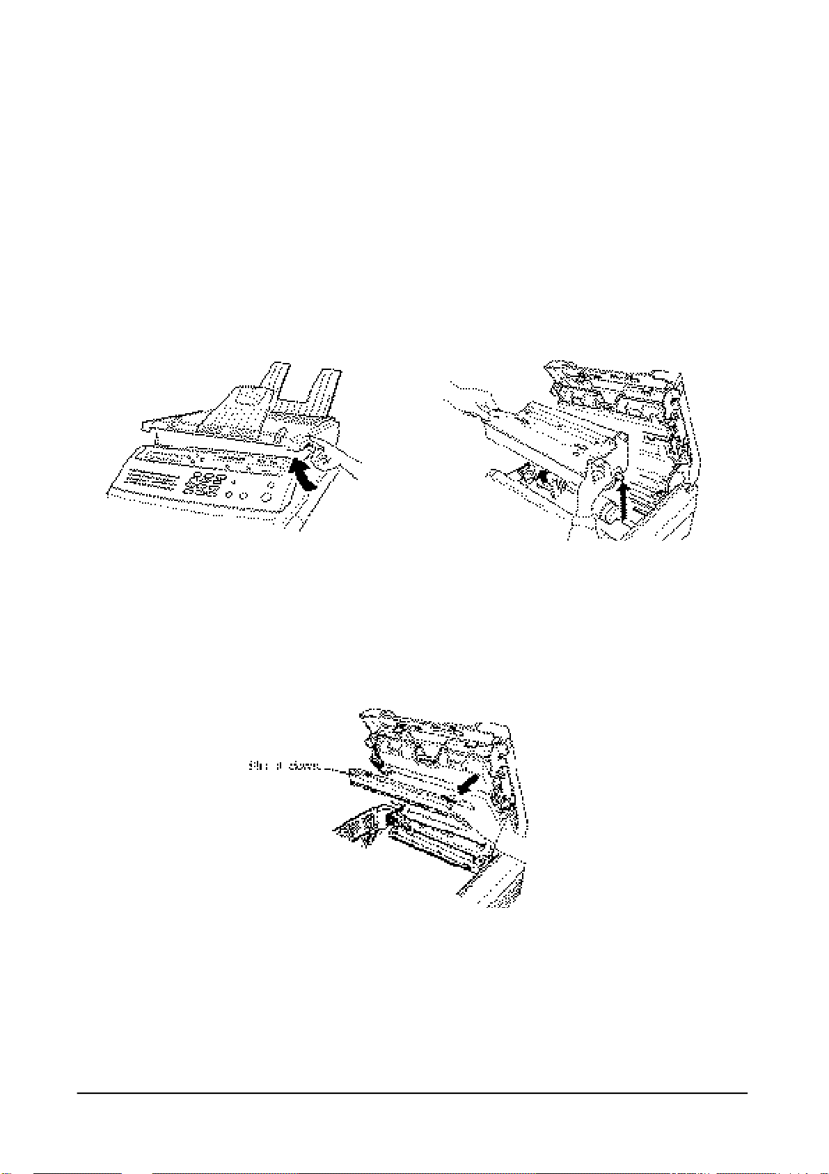
1. Open the top cover by lifting up the cover release lever.
2. Hold the toner cartridge by the end tabs and remove the used cartridge.
3. Take a new toner cartridge out of the foil bag and install the new cartridge as described in "Installation
of the Toner Cartridge" on page 2-3.
4. Flip down the tab on the top of the holder and lower the top cover halfway.
6-1
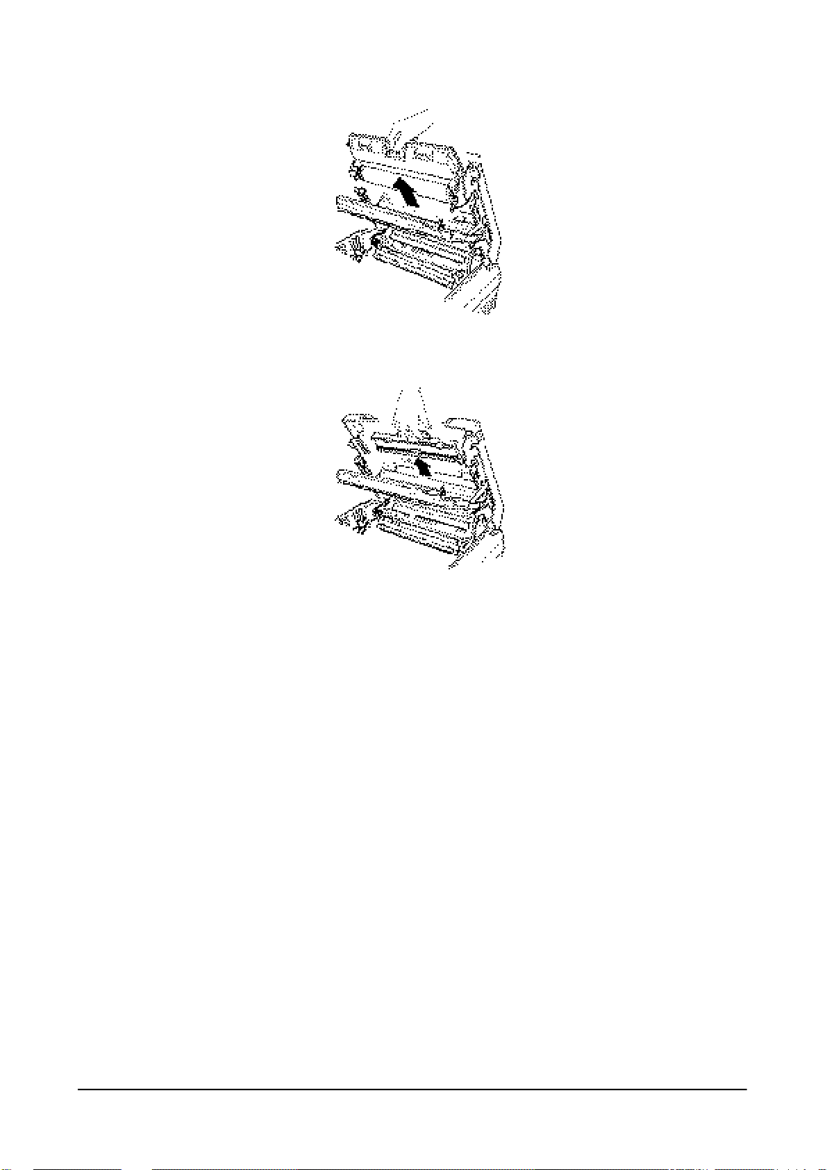
5. Hold the handle of the used drum cartridge and remove the cartridge by pulling it out of the unit.
6. Hold the handle of the fuser felt and remove the fuser felt by pulling it out of the unit.
7. Install a new drum cartridge and a fuser felt as described in "Installing Drum Cartridge" and "Installing
the Fuser Felt" on page 2-4 and 2-5.
Notes
• Do not expose the drum cartridge to direct room light or sunlight for more than a few minutes.
• Do not place the drum cartridge neat a window or in an area subject to high heat (above 50°F) or high
humidity (above 80 %)
• Do not touch the drum surface. Lift the drum cartridge by the handle only.
• Keep the drum cartridge away from dust and dirt.
6-2

6.2 REPLACEMENT OF COMPONENTS
6.2.1 GENERAL NOTES AND CAUTIONS
While removing and installing the components, it is necessary to use extreme caution. The close proximity of
cables to moving parts makes proper routing a must. If modules are removed or replaced, any cables disturbed by
the procedure must be restored as close as possible to their original positions. Before removing any module from
the machine, note the cable routing that will be affected.
Take the following precautions whenever servicing the machine.
1. Check to verify that no documents are stored in memory. If so, wait until memory is empty.
2. Turn off the power switch and unplug the power cord.
3. Unplug all line cord.
4. Remove the recording paper cassette, all trays, toner cartridge, drum cartridge, and fuser felt.
5. Place the drum and toner cartridges in a safe place away from light.
The following are removal instructions for the major components of the fax machine. Generally, replacement
procedures are the reverse of those for removing components. Where a replacement procedure differs from the
way the component is removed, or where a particular aspect of a replacement procedure needs clarification, a
reassembly note is provided.
6.2.2 REAR COVER
Note: When installing the rear cover, insert three ribs of the rear cover into the corresponding holes of the
middle cover.
1. Remove the two screws from the rear cover.
2. open the top cover and remove the rear cover.
6-3
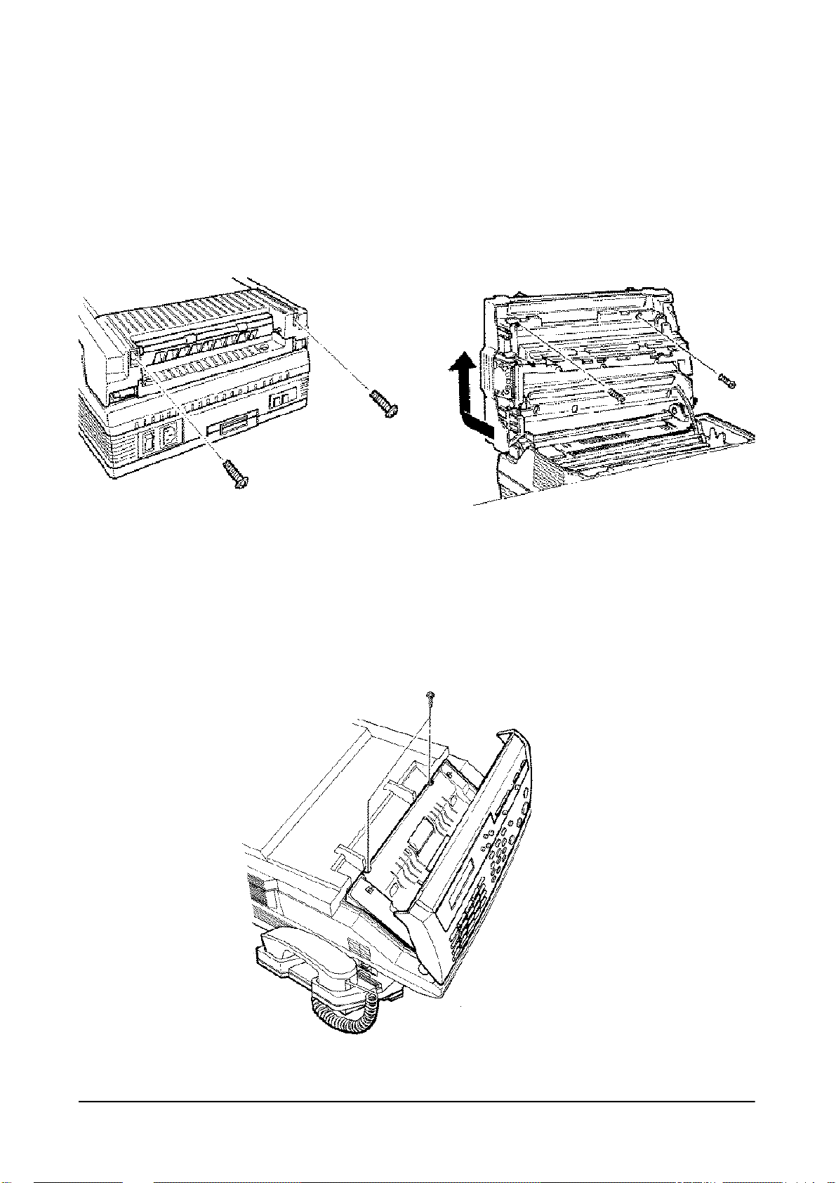
6.2.3 TOP COVER
Note: When installing, close the top cover frame then replace the cover, and reverse the removal procedure.
1. Remove the two screws from the top cover.
2. Open the top cover and remove the two screws.
3. Lift the top cover up while pushing the rear end of the cover backward.
Push the bottom
side of the cover
backward.
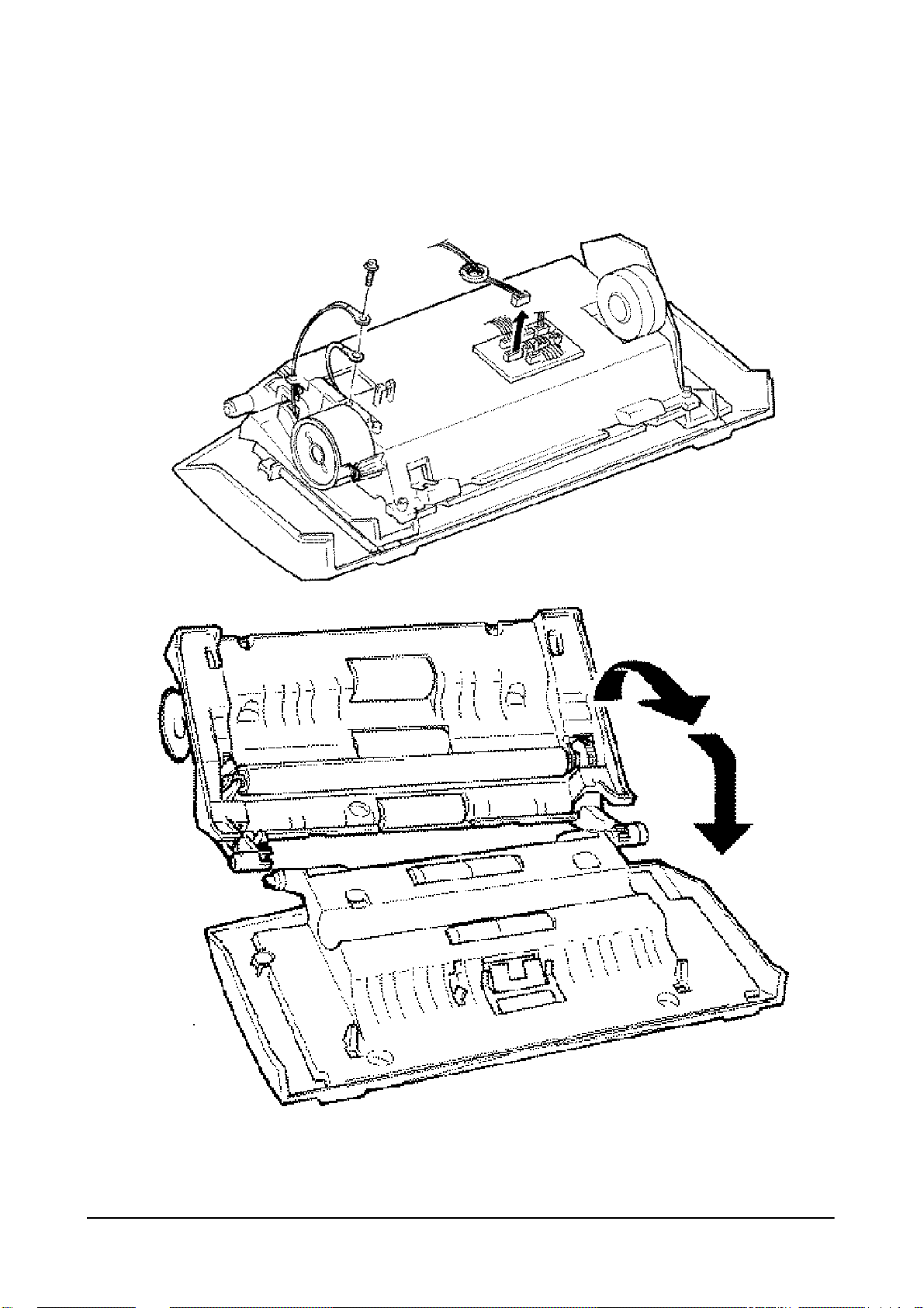
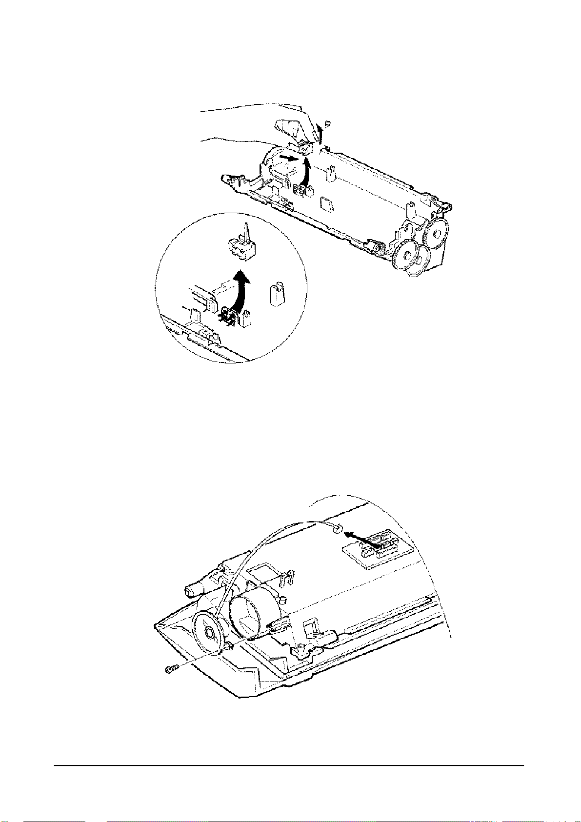
6.2.4 SCANNER MECHANISM ASS’Y
1. Open the control panel and remove the two screws.
6-4

2. Close the control panel and remove the scanner mechanism assembly. When you remove the assembly,
do not lift it directly up. Pull the cover by rotating slightly toward you away from the base frame.
3. Unplug the connector from the main PBA.
Note: When replacing the scanner mechanism assembly, be sure that the assembly fits to the groove on the
base frame as shown in the circle.
Harness
6.2.5 MIDDLE COVER
1. Remove the scanner mechanism assembly, rear cover, and top cover.
2. Remove the six screws securing the middle cover
3. Before lifting up the middle cover, slide it backward until the ventilation holes on the cover aligns with
the stand-up frame, then lift it up.
Vertilation
Holes
Middle Cover
6-5

6-6
6-7
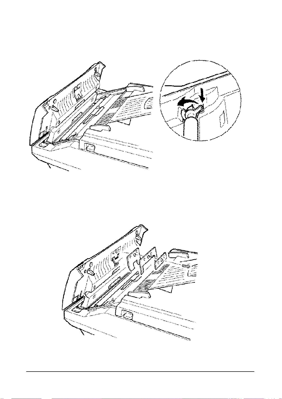
6.2.6 WHITE ROLLER ASSEMBLY
1. Open the control panel.
2. Push the bushing on the both end of the roller slightly inward, then rotate it until it reaches the slot as
shown in the figure below. Then lift the roller up.
6-8

6.2.7 ADF RUBBER PAD
1. Open the control panel.
2. Remove the one screw securing the ADF pad. The ADF plate, ADF spring, and ADF rubber pad are
6-9

separated.
6-10
6.2.8 OPERATION UNIT
1. Remove the scanner mechanism assembly.
2. Turn the scanner assembly upside down and unplug the ope connector from the scan PBA and remove the
one earth screw.
3. Open the operation panel completely to separate the operation unit from the scanner
6-11

6.2.9 ClS
Note: When replacing the scan paper guide, be sure that the guide fits to the hole on the front end of the
scanner unit.
1. Remove the scanner mechanism assembly. Remove the white roller.
2. Turn the scanner assembly upside down and unplug the connector from the CIS.
3. Remove the two screws securing the scan paper guide. Take out the scan-paper guide.
6-12

6.2.10 ROLLERS (ADF, FEED, P.EXIT)
1. Remove the scanner mechanism assembly, operation unit and white roller assembly
2. Remove the two screws securing the scan paper guide. Take out the scan paper guide.
3. Take out the rollers.
6-13

6.2.11 DOCUMENT SCAN SENSOR
1. Remove the scanner mechanism assembly, operation unit, and white roller assembly.
2. Turn the scanner unit upside down and unplug the sensor connector from the scan PBA.
6-14

3. Remove the two screws securing the scan paper guide. Take out the scan paper guide.
4. Take out the document sensor while pressing down one end of the sensor using your thumb and lifting
up the other end of the sensor with another finger.
6.2.12 SPEAKER
1. Remove the scanner mechanism assembly.
2. Turn the scanner unit upside down and unplug the speaker connector from the scan PBA.
3. Remove the two screws securing the scan paper guide. Take out the scan paper guide.
4. Remove the two screws securing the speaker, and take out the speaker.
6-15

6.2.13 SCAN MOTOR
1. Remove the scanner mechanism assembly, operation unit, and white roller assembly.
2. Turn the scanner unit upside down and unplug the motor connector from the scan PBA.
6-16

3. Remove the two screws securing the scan paper guide. Take out the scan paper guide.
4. Remove all rollers in the scanner unit.
5. Remove the two screws to disassemble the motor assembly.
6. Remove the two screws securing the motor to the motor bracket.
6-17

6.2.14 ROLL PINCH
1. Remove the scanner mechanism assembly and operation unit
2. Remove the four screws in the operation unit.
3. Turn the operation unit upside down and remove the two screws secure~4~he spring pinch.
4. Take out the spring pinch. The roll pinches are separated.
6-18

6.2.15 SPRING COIL
1. Remove the scanner mechanism assembly and operation unit.
2. Remove the four screws in the operation unit to separate the scanner upper frame.
3. Remove the spring coil from the hook.
6.2.16 SCAN PBA
1. Remove the scanner mechanism assembly.
2. Turn the scanner unit upside down and unplug all connectors from the scan PBA.
6-19

3. Remove the two screws securing the scan PBA and take the PBA out.
6-20

6.2.17 OPERATION PBA
1. Remove the scanner mechanism assembly and operation unit.
2. Remove the four screws in the operation unit to separate the scanner upper frame.
3. Remove the fourteen screws securing the operation PBA and LCD, then take out the PBA and the LCD.
Notes
• Do not turn the operation unit upside down after you remove the screws securing the PBA. Keys and
rubber contacts may be separated and you might lose them.
• When disassembling the operation unit, place the unit on a soft cloth to avoid accidentally scratching the
surface of the unit.
6.2.18 HOOK PBA
1. Unhook the tab on the bottom of the cradle from the main body, then unhook the two tabs on the side of
6-21

the cradle.
2. Unplug the modular cords from the main body and from the cradle.
3. Turn the cradle upside down and remove the two screws to separate the cradle upper frame and lower
the frame.
6-22

4. Remove the two screws securing the hook PBA and take out the PBA.
6-23

6.2.19 MAIN PBA
1. Remove the scanner mechanism assembly.
2. Unplug all connectors from the main PBA.
3. Remove the two screws securing the main PBA and take out the PBA.
6-24

6.2.20 LIU PBA
1. Remove the scanner mechanism assembly.
2. Unplug the connectors from the main PBA.
3. Unplug connectors and earth plug from the LIU PBA.
4. Remove the two screws securing the LIU PBA and take out the PBA.
6-25

6.2.21 CONNECTION PBA
1. remove covers and the scanner mechanism assembly.
2. Unplug all connectors from the scan PBA.
3. Remove the one screw securing the connection PBA and take out the PBA.
6.2.22 HVPS UNIT
6-26

1. Remove covers and the scanner mechanism assembly.
2. Unplug one connector from the main PBA.
3. Remove the one screw securing the HVPS unit.
4. Unplug the earth wire and the three bias plugs in the HVPS.
6-27

6.2.23 MOTHER PBA
1. Remove the engine mechanism.
2. Unplug all connectors from the mother PBA.
6-28

3. Remove the two screws located near the power switch.
4. Remove the nine screws securing the mother PBA and take out the PBA.
6.2.24 MECH PBA
6-29

1. Remove the engine mechanism.
2. Unplug the connectors from the mech PBA.
3. Remove the three screws securing the mech PBA and take out the PBA.
6-30

6.2.25 SMPS UNIT
1. Remove the rear cover.
2. Remove the one screw securing the cap ground and take the cap ground out.
3. Remove the screw securing earth plug and two screws securing the SMPS unit.
4. Take out the SMPS and unplug the one connector from the PBA in the SMPS unit.
6-31

6.2.26 SENSOR PBA
1. Remove the engine mechanism.
2. Remove the one screw securing the harness cover.
6-32

3. Unplug the connector from the sensor PBA.
4. Remove the two screws securing the sensor PBA and take out the PBA.
6.2.27 FAN
1. Remove the covers and the scanner Mechanism Assembly.
2. Remove the two screws securing the fan.
3. Unplug the connector from the Mech PBA.
6-33

4. Take out the fan and the filter.
Note: When reinstalling the fan, route the connector cord through the recessed channel on the harness.
6-34

6.2.28 ENGINE MECHANISM ASSEMBLY
1. Remove the two screws holding the ground wires on the top of the SMPS Unit.
2. Remove the four screws securing the Engine Mechanism Assembly.
3. Disconnect the two connectors from the Main PBA
4. Lift the Engine Mechanism from the Lower Cover.
6-35

6.2.29 ENGINE UPPER FRAME UNIT
1. Remove the engine mechanism assembly.
6-36

2. Remove the one screw securing the harness cover.
3. Unplug the connectors (Paper LPH, Thermistor, and Paper Exit) from the sensor PBA.
4. Unplug the fuse connector and fan connector from the mech PBA.
5. Remove the two E-rings and release the tie stopper.
6. Remove the two shafts securing the engine upper frame.
6-37

6.2.30 FUSER UNIT
1. Remove the engine mechanism assembly.
2. Remove the cover wire.
3. Remove the one screw securing the harness cover.
6-38

4. Unplug the thermistor connector from the sensor PBA.
5. Remove the four screws and take out the fuser unit.
6-39

6.2.31 HEAT LAMP
1. Remove the Fuser unit.
2. Remove the two screws securing the upper fuser and remove the exit roller.
3. Remove the two screws securing the guide inlet and take out the guide inlet.
4. Turn the fuser unit upside down and remove the two screws securing the heat lamp.
5. Turn the fuser unit right-side-up and remove the two screws at the bottom and take out the fuser cover.
6. Remove the lamp holder and take out the heat lamp.
6-40

6.2.32 THERMOSTAT
1. Remove the fuser unit.
2. Remove the two screws securing the upper fuser and remove the exit roller.
3. Turn the fuser upside down and remove the two screws securing the guide~inlet and remove the guide
inlet.
4. Remove the two screws securing the heat lamp on both ends.
5. Remove the two screws at the bottom and take out the fuser cover.
6. Remove the one screw securing the thermostat and remove the thermostat.
6-41
 Loading...