

Samsung SF-5500, SF-5600 Service manual

CONTENTS
Chapter 1 SPECIFICATION
1.1 Basic Features 1-1
1.2 Technical Parameters 1-2
Chapter 2 INSTALLATION
2.1 Installation Procedure 2-1
2.2 Unpacking 2-2
2.3 Installation 2-3
2.3.1 Installation Location 2-3
2.3.2 Installation Toner Cartridge 2-3
2.3.3 Installation Fuser Felt 2-4
2.3.4 Installation Drum Cartridge 2-5
2.3.5 Installation Handset and Handset Cradle 2-7
2.3.6 Installation Paper Cassette 2-8
2.3.7 Installation Document Feeder Tray 2-9
2.3.8 Installation Document Exit Tray 2-9
2.3.9 Installation Recording Paper Tray 2-9
2.3.10 Conneting Phone Line 2-10
2.3.11 Conneting Extension Telephone or Answering Machine 2-10
2.3.12 Conneting Power Cord 2-10
2.3.13 Turn On Power 2-11
2.3.14 Mount Address Label 2-11
2.3.15 Initialize New Toner Cartridge 2-12
2.3.16 Adjust Ringer Volume 2-12
2.4 Memory Clear 2-13
2.5 System Data set-up 2-13
2.5.1 System Data Settings In User-Mode 2-13
2.5.2 System Data Settings In Tech-Mode 2-18
2.6 Confirming System Data settings 2-19
Chapter 3 THEORY OF OPERATION
3.1 Function Block Diagram 3-1
3.1.1 Main Block Diagram 3-1
3.1.2 Copy Operation 3-2
3.1.3 G3 Transmission 3-3
3.1.4 G3 Reception 3-4
3.1.5 OGM Operation 3-5
3.2 Protocol 3-6
3.2.1 Protocol 3-6
3.2.2 G3 Signals 3-8
3.3 Modulation 3-9
3.3.1 G3 Modems 3-9
3.3.2 Phase Modulation 3-9
3.3.3 Ouadrature Amplitude Modulation 3-9
3.3.4 Trellis Coded Modulation (TCM) 3-9
3.4 Mechanical Operation 3-10
3.4.1 Sectional View 3-10
1

3.4.2 Scanner Mechanism 3-11
3.4.3 Printer Mechanism 3-11
3.4.5 Development Process 3-13
3.4.6 Recording Timing Diagram 3-14
Chapter 4 ELECTRICAL DESCRIPTION
4.1 Connetingion Diagram 4-1
4.2 Inter-Unit Signal Diagram 4-8
4.3 Printed Board Assembly View 4-11
4.4 PBA Circuit Description 4-12
4.4.1 Main PBA 4-12
4.4.2 OPE PBA 4-13
4.4.3 Scan PBA 4-13
4.4.4 LIU PBA 4-13
4 4.5 Mother PBA 4-14
4.4.6 Connetingion PBA 4-14
4.4.7 Mech PBA 4-14
4 4.8 Sensor PBA 4-15
4.4.9 Hook PBA 4-15
4.4.10 SMPS 4-15
4.4.11 HVPS 4-15
4.5 Sensors 4-16
4.5.1 Sensor Location 4-16
4.5.2 Sensor Table 4-16
Chapter 5 MAINTENANCE & TROUBLESHOOTING
5.1 Preventive Maintenance 5-1
5.2 Diagnostics 5-1
5.2.1 Error Messages 5-1
5.2.2 Test Mode 5-4
5.2.3 Maintenance List 5-5
5.3 Remote Diagnosis and Control 5-6
5.4 Troubleshooting Guide 5-10
5.4.1 Telephone Screening 5-10
5.4.2 Recommended Flow For Telephone Screening 5-11
5.4.3 Overall Troubleshooting 5-14
5.4.4 System Not Initialized (System reset) 5-15
5.4.5 Trouble in Copy Mode 5-16
5.4.6 Trouble in Transmission 5-17
5.4.7 Trouble in Manual Reception Mode 5-18
5.4.8 Trouble in Tel/Fax Auto-Switching 5-19
5.4.9 Trouble in Ans/Fax Auto-Switching 5-20
5.4.10 Trouble in Telephone Operation 5-21
5.4.11 Trouble in OGM Recording/Playing 5-22
5.4.12 NO Printing of the Image (AII white printed) 5-23
5.4.13 Pale/Weak Image Ouality 5-25
5.4.14 High Background Density 5-26
5.4.15 Uneven Density 5-27
5.4.16 All Black Printed 5-28
5.4.17 Black Vertical Line 5-29
5.4.18 Black Horizontal Line 5-30
2

5.4.19 White Vertical Line 5-31
5.4.20 Periodic Black Spot 5-32
5.4.21 A Void in the Image 5-32
5.4.22 Image Shake/Jitter 5-33
5.4.23 Image Noise 5-34
5.4.24 Incomplete Fusing 5-34
Chapter 6 REMOVALS AND REPLACEMENTS
6.1 Replacement of The Consumables 6-1
6.2 Replacement of Components 6-3
6.2.1 General Notes and Cautions 6-3
6.2.2 Rear Cover 6-3
6.2.3 Top Cover 6-4
6.2.4 Scanner Mechanism Ass'y 6-4
6.2.5 Middle Cover 6-5
6.2.6 White Roller Ass'y 6-6
6.2.7 ADF Rubber Pad 6-6
6.2.8 Operation Unit 6-7
6.2.9 CIS 6-8
6.2.10 Rollers (ADF, Feed, P.EXit) 6-9
6.2.11 Document Scan Sensor 6-9
6.2.12 Speaker 6-10
6.2.13 Scan Motor 6-10
6.2.14 Roll Pinch 6-11
6.2.15 Spring Coil 6-12
6.2.16 Scan PBA 6-12
6.2.17 Operation PBA 6-13
6.2.18 Hook PBA 6-13
6.2.19 Main PBA 6-14
6.2.20 LIU PBA 6-15
6.2.21 Connetion PBA 6-16
6.2.22 HVPS Unit 6-17
6.2.23 Mother PBA 6-18
6.2.24 Mech PBA 6-18
6.2.25 SMPS Unit 6-19
6.2.26 Sensor PBA 6-20
6.2.27 Fan 6-20
6.2.28 Engine Mechanism Assembly 6-21
6.2.29 Engine Upper Frame 6-22
6.2.30 Fuser Unit 6-23
6.2.31 Heat Lamp 6-24
6.2.32 Thermostat 6-26
6.2.33 Paper Exit sensor 6-27
6.2.34 Cover Open Switch 6-27
6.2.35 Pick-Up Clutch 6-28
6.2.36 Feed Roller 6-29
6.2.37 Pick-Up Pad Assembly 6-30
6.2.38 RX Motor 6-31
6.2.39 Gear Box 6-31
6.2.40 AC Toner Motor 6-32
6.2.41 Transfer Unit 6-33
6.2.42 Pick-Up Roller 6-34
3

6.2.43 Paper Empty Sensor 6-35
6.2.44 Pick-Up Sensor 6-35
6 2.45 LPH 6-36
Chapter 7 EXPLODED VIEWS and PARTS LISTS
7.1 Main Assembly 7-1
7.2 OPE Unit Assembly 7-3
7.3 Base Unit Assembly 7-5
7.4 Scan Unit Frame Assembly 7-7
7.5 Engine Unit Upper Frame Assembly 7-9
7.6 Engine Unit Lower Frame Assembly 7-11
7.7 Pick-Up Unit Assembly (in engine unit) 7-14
7.8 Feed Roller Unit Assembly (in engine unit) 7-15
7.9 Transfer Unit Assembly 7-16
7.10 Cradle Unit Assembly 7-17
7.11 Harness Assembly 7-18
Chapter 8 ELECTRICAL PARTS LIST
8.1 Main PBA 8-1
8.2 LIU PBA 8-9
8.3 Ope. PBA 8-11
8.4 Scan PBA 8-13
8.5 Mother PBA 8-14
8.6 Mech PBA 8-15
8.7 Sensor PBA 8-15
8.8 Hook PBA 8-15
8.9 CONN PBA 8-15
8.10 Others 8-16
8.11 Power Supply 8-18
Chapter 9 ELECTRONIC CIRCUIT DIAGRAM
4

CHAPTER 1
Specifications

1-1
CHAPTER 1 SPECIFICATIONS
1.1 BASIC FEATURES
Machine type : Desk Top
Applicable lines : Public Switched Telephone Network (PSTN) or behind PABX
Compatibility : CCITT Group 3, ECM
Data cording : MH / MR / MMR
Modem speed : 14400 / 12000 / 9600 / 4800 / 2400 bps
Transmission speed : Approx. 6 sec. (MMR)
Effective scanning width : 8.3 inches (210 mm)
Effective printing width : 8.2 inches (208 mm)
Scanning method : Flat bed scanning using a contact image sensor (CIS)
Memory : 1256 KByte (including ECM buffer 64 KByte)
Halftone : 16 levels
Printing speed : 5 PPM (A4 size)
Automatic document feeder : 20 pages
TEL/FAX switching : Automatic
Phone : Built-in handset
One-touch dial : 20 locations
LCD : 16 characters x 2 lines
Dimension (H x W x D) : 7.7 x 13.6 x 16.4 inches (195 x 346 x 416 mm)
(trays and cassette excluded)
Weight : Approx. 12.5 kg (recording paper excluded)
Power : 120 VAC / 60 Hz

1-2
1.2 TECHNICAL PARAMETERS
SCANNER
Scanning Method : Flat bed scanning by CIS and step feeding of the document by a stepping
motor
Resolution
Horizontal : 8 dots/mm (203 dpi)
Vertical
STANDARD : 3.85 lines/mm (98 lpi)
FINE : 7.7 lines/mm (196 lpi)
SUPER FINE : 15.4 lines/mm (391 lpi)
Photo scale : 16 shades
Scanning period
STANDARD : 10 ms/line
FINE : 5 ms/line
SUPER FINE : 5 ms/line
Document size
Width : 5.8 to 8.5 inches (148 to 216 mm)
Length
Single page : 5 to 14 inches (128 to 356 mm)
Multi page : 5 to 11.7 inches (128 to 297 mm)
Manual assistance : infinite
Weight
single page : 12.5 lb. - 32 lb. (Thickness 0.075 - 0.15 mm)
Multi page : 12.5 lb. - 24 lb. (Thickness 0.075 - 0.15 mm)
Automatic document feeder (ADF)
Letter size : 20 Sheets
Class 1-5 : 10 Sheets
Class 1-3 : 20 Sheets
Thickness of document according to each class (letter size)
Scanning position
Top edge : 2 mm ± 2 mm (0.079 ± 0.079 inch)
Bottom edge : 0 mm ± 2.5 mm (0 ± 0.098 inch)
CLASS THICKNESS WEIGHT (U.S. POUND)
1 0.075 mm 12.5 Ib
2 0.10 mm 20.0 Ib ADF: 20 sheets
3 0.12 mm 24.0 Ib ADF: 10 sheets
4 0.13 mm 28.0 Ib
5 0.15 mm 32.0 Ib

1-3
PRINTER
Recording method : Electrostatic image recording with LED array
Printing speed
Letter : 5 pages/minute
Recording density
Horizontal : 8 dots/mm (203 dpi)
Vertical : 7.7 lines/mm (196 lpi)
Recording paper size
Size
Letter : 8.5 x 11 inches (216 x 279 mm)
Legal : 8.5 x 14 inches (216 x 356 mm
Weight : 16 - 24 lbs (60 - 90 g/m2)
Thickness : 0.08 - 0.12 mm
Recording paper cassette
Basic cassette
Msys 5600 : Letter 250 sheets
Msys 5700 : Letter 500 sheets
Reference weight : 75 g/m2 (20 lbs)
Maximum Reduction : Legal → Letter
Effective recording area
First sheet copying time : Less than 30 seconds
Warm up time : Less than 60 seconds (at ambient temperature of 25°C)
Recording paper stack
Type : Face up stack
Capacity : 100 sheets
Reference weigh : 75 g/m2(20 lbs)
Printing density and uniformity
Density : Greater than 1.0 O.D (Optical Density)
Uniformity : Less than 0.3 O.D
EFFECTIVE RECORDING AREA
3 mm
4 mm
3 mm
4 mm

1-4
AUTO DIALER
Pulse dialer
Pulse rate : 10 + 0.8 pps
Break ratio : 58 - 64 %
Interdigit pause : 700 ms - 1 sec
Loop resistance
Break period : 100 kohm min. tip, ring
Make period : 300 kohm max. tip, ring
Pause time : 3.3 sec ± 0.3 sec.
MF dialer
Frequencies (tolerance: ± 1.5%)
Output level
Lower freq. level : -8 ± 2 dBm at 20 mA
Higher freq. level : -6 ± 2 dBm at 20 mA
Twist level : 2 ±l dBm at 20 mA
Timing
1 digit duration : 100 msec. min.
Interdigit pause : 45 msec. - 3 sec.
Access pause : 3.3 sec. ± 0.3 sec.
MODEM
Modulation
Group 3/ ECM : CCITT V.17 (FX5600)
: CCITT V.29 V.27ter
Binary signal : CCITT V.21 T.30
Tonal signal : CCITT V.30
SOUND
Key click : Frequency 1.6 kHz, Duration 30 msec.
Alarm : Frequency 1.6 kHz, Duration 2 sec.
Transmission completion : Normal 1 sec. / Error 1 sec.
Operator call : 15 sec. (1.28 sec On /1.28 sec Off)
L
H 1209 Hz 1336 Hz 1477 Hz
697 Hz 1 2 3
770 Hz 4 5 6
852 Hz 7 8 9
941 Hz * 0 #

1-5
LINE INTERFACE
Off hook DC loop resistance
Tip-ring : 50 - 220 ohm
Input impedance : 600 ohm ± 30% at 300 - 3400 Hz
On hook
Ring sensitivity
Ring voltage : 40 - 150 Vrms
Frequency : 15.3- 68 Hz
Duration : 180 msec. min.
On-hooK DC resistance
Tip-ring : 1600 ohm min.
Tip-ring earth : 100 kohm min.
Condition : 40 - 150 Vrms, DC 52.5 V, 15.3 - 68 Hz
POWER SUPPLY
Input voltage : 120 VAC / 60 Hz
Power consumption
Standby : 16 watts
Copy : 490 watts
Power cord length : 2.7 m + 20 cm /-0 cm
Power switch : Available
High Voltage power supply
Input : 24 Vdc, 1.0 A
Output : 3.8 KVdc at 40 Mohm
-4.4 KVdc at 22 Mohm
ENVIRONMENT
SAFETY : UL1950 / CSA No. 220
RFI : FCC part 15 Class A
Ambient Temperature
50°F ~ 86°F (10°C ~ 30°C)
-1 3°F ~ 1 58°F (-25°C ~ 70°C)
-4°F ~ 95°F (-20°C ~ 35°C)
95°F ~ 104°F (35°C ~ 40°C)
-4°F ~ 95°F (-20°C - 5°C)
95°F ~ 113°F (35°C - 45°C)
Relative Humidity
30 ~ 80%
20 ~ 90%
35 ~ 85%, 2 years
10 ~ 35%, 85 ~ 90% 360 hours
10 ~ 91%, 2 years
10 ~ 90%, 360 hours
Storage
Operation
Body
Durm
Toner

CCHAPTER 2
Installation

2-1
Chapter 2 INSTALLATION
2.1 INSTALLATION PROCEDURE
Please install the machine according to the following flow chart.
START
UNPACK
INSTALL THE FAX MACHINE
CLEAR ALL MEMORY
SET SYSTEM DATA IN USER MODE
SET SYSTEM DATA IN TECH MODE
CONFIRM SYSTEM DATA SETTING
MACHINE ORIENTATION FOR USERS
END

2-2
2.2 UNPACKING
Open the carton and remove the fax machine and accessories. Check the contents to see if anything is
damaged or missing in reference to the figure below.
2-3
2.3 Installation
Choose a proper location for the fax machine, then install the machine according to the following
description.
2.3.1 INSTALLATION LOCATION
Please do not install your facsimile machine where there is a danger of:
1. Overheating
- Allow at least 10 Inches clearance from the top and the side of your unit.
- DO not Install your unit In direct sunlight.
2. Improper Ventilation
- Do not block the ventilation openings or the exhaust fan.
3. Others
- Do not place it in airtight room.
- Do not place it where water or chemical splashes may occur.
- Do not place it near an air conditioner, or in a dusty enviroment.
- Keep your fax unit on a level, vibration-free surface.
Note: Protect your unit from excessive neat and humidity. Use it in a normal
room temperature (10°C - 30°C, 30 % - 80 % RH)
2.3.2 INSTALLATION OF THE TONER CARTRIDGE
1. Take the toner cartridge out of its protective bag, and remove
the shield cover. Remove the green shield cover from the
toner unit.
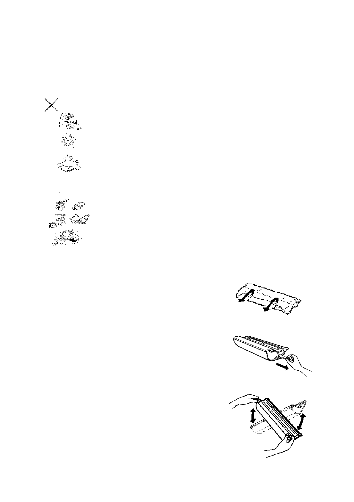
2. Remove the sealing tape at the side of the toner unit by
pulling it straight out. Be careful not to tear it off.
3. Hold the toner cartridge in both hands with the green tabs on
the top of the unit Rotate the cartridge several times gently
from side to side to distribute the toner inside the unit evenly.
2-4
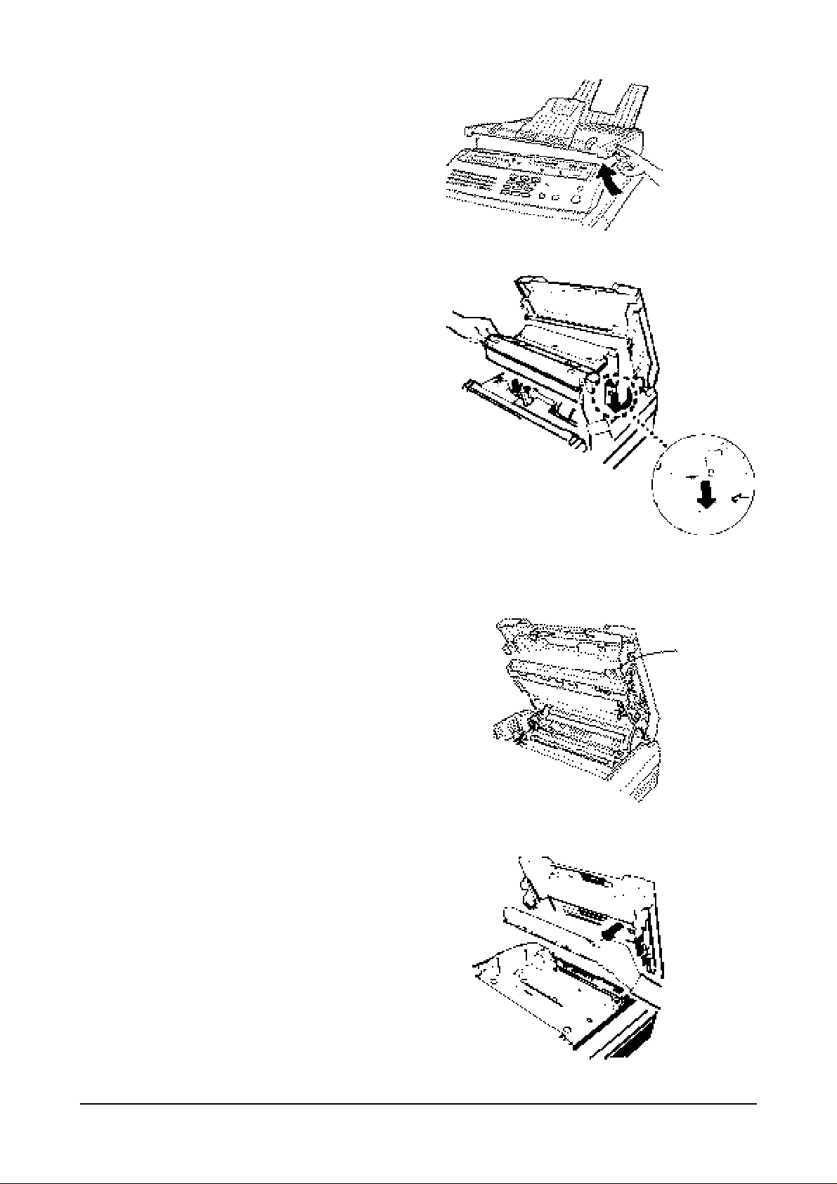
4. Open the top cover by lifting up the cover release
lever.
5. Holding the cartridge in both hands, fit the two tabs
on the bottom of the cartridge into the grooves
(marked by green label) on both sides of the
compartment, and slide it down into your fax
machine.
2.3.3 INSTALLATION OF THE FUSER FELT
1. Take the fuser felt out of its protective bag.2. Grasp the
tab as shown and pull it towards you.
3. Holding the handle of the fuser felt, insert it into the
slot indicated by the green arrows.
Lift it up
Fit it into the groove.
Fit it down.
2-5
4. Slide it down until it snaps in place.
2.3.4 INSTALLATION OF THE DRUM CARTRIDGE
The drum cartridge is photosensitive. Exposing it to light may damage the drum and result in poor print
quality. Do not open the drum cartridge's protective bag until you have read the following instructions and
are ready to install the drum.
Warning !
Do not expose the drum cartridge to direct room light or sunlight for more than a few minutes.
Do not place the drum cartridge near a window or in an area subject to high heat (above 50°C) or high
humidity (above 80% RH).
Do not touch the drum surface. Lift the drum cartridge by the handle only.
Keep the drum cartridge away from dust and dirt.
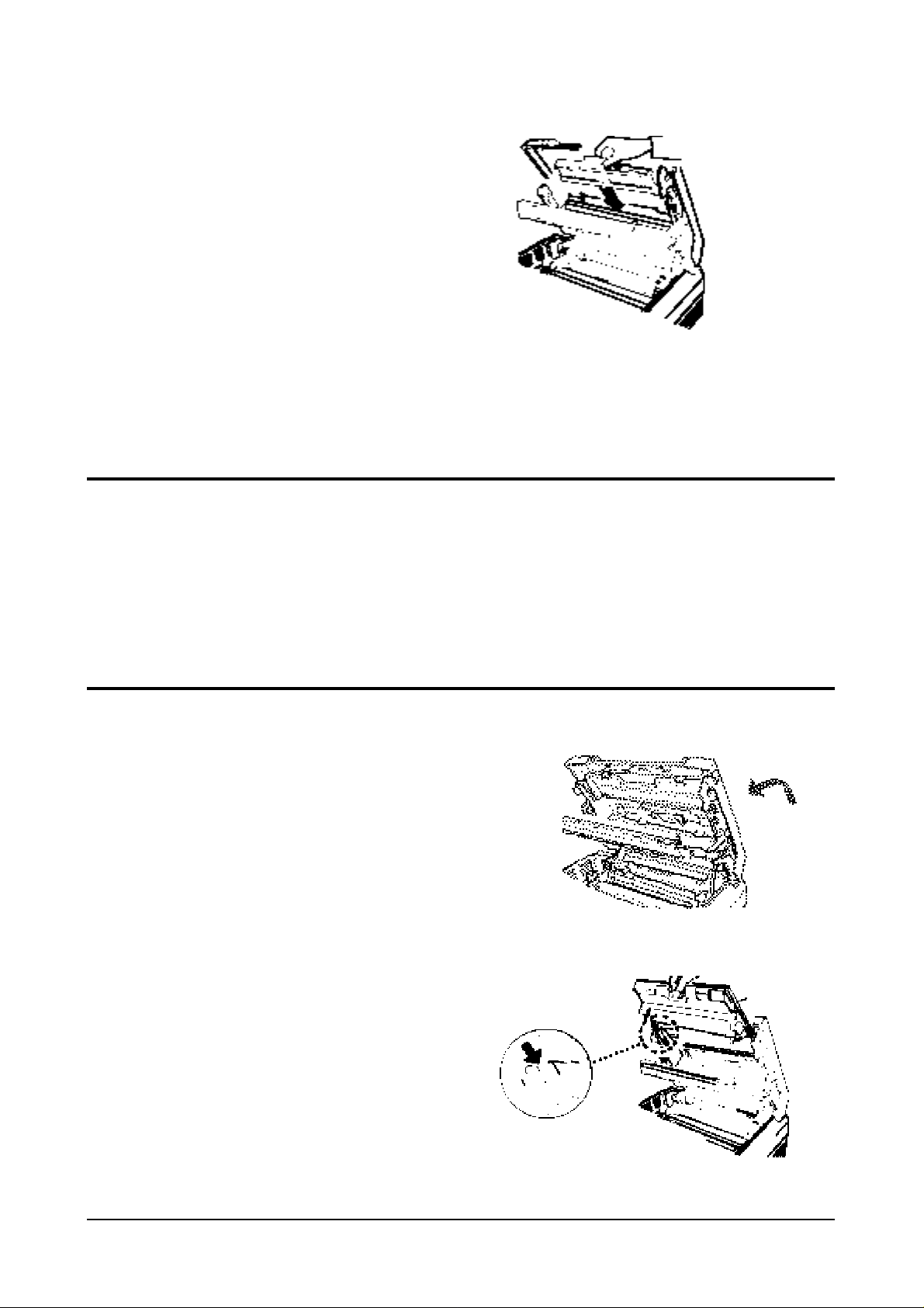
1. Take the drum cartridge out of its protective bag.
2. Lower the tap cover half-way. It makes the cartridge
easier to install.
3. Holding the handle of the drum cartridge, fit the
narrow tabs at both ends of the cartridge in the
grooves indicated by green bar.
Fit it into the
groove.
Insert the fuser felt
here
2-6
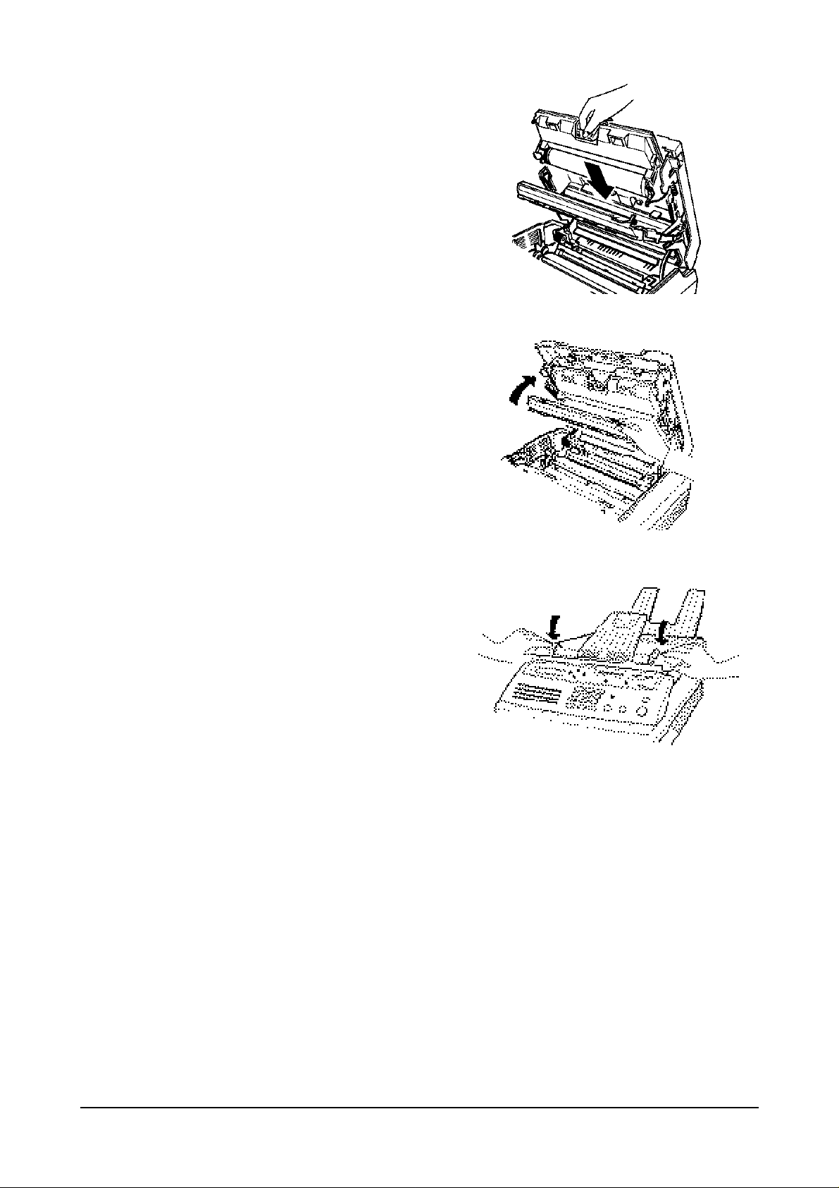
Carefully slide It down until it locks into place.
4. Close the holder.
5. Close the top cover. Press firmly to be sure both sides
of the cover are securely
Note: Whenever you install a new developer, you should perform the toner cartridge initialization. see
"Initializing a New Toner Cartridge".
2-7
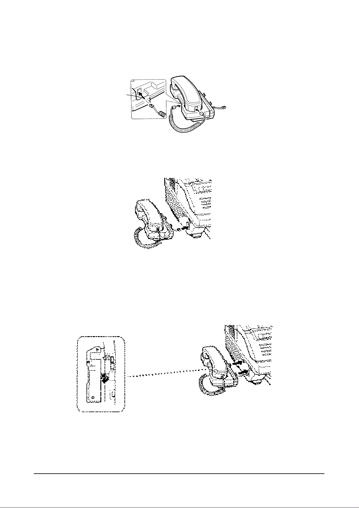
2.3.5 INSTALLATION OF THE HANDSET AND HANDSET CRADLE
1. Plug one end of the coiled cord into the handset. Then, plug the other end into the modular jack on the
bottom of the handset cradle.
2. Plug the cradle's modular cord into the modular jack on the left side of your fax machine.
3. With the cradle held at a slightly downward angle, insert the two tabs on it into the slots on the left side of
your unit and lower the cradle.
If you want to remove the cradle, lift the front of the unit and
release the hooked tab on the bottom of the cradle from the unit
before you release the upper two tabs on the cradle
Push the cradle in while feeding
in the excess cord.
2-8
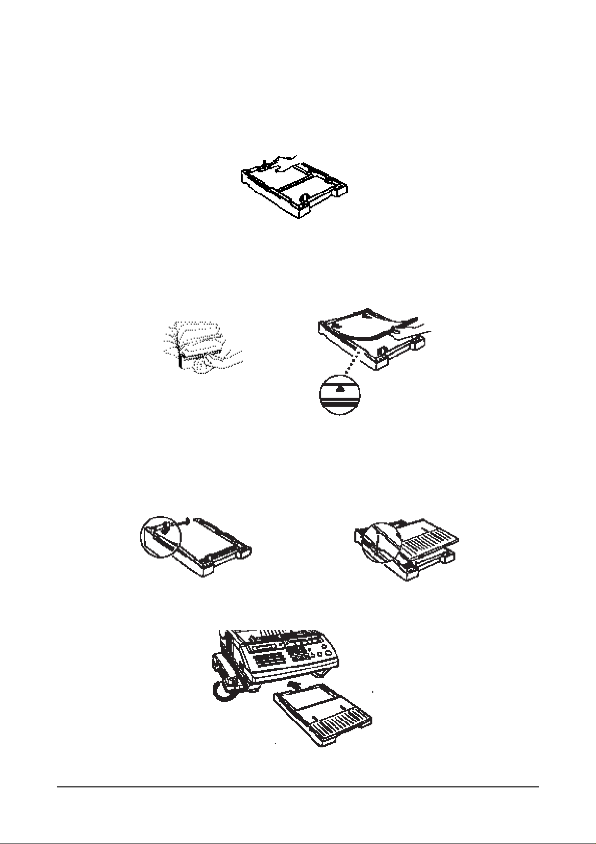
2.3.6 INSTALLATION OF THE PAPER CASSETTE
Msys5600/5700 come with a paper cassette that holds up to 250 sheets of letter-size paper, and the
Msys5700 holds up to 500 sheets of letter-size paper.
1. To load the paper into the cassette, remove the cassette cover. Then, press down the metal plate in the
cassette.
2. Fan the paper to separate the sheets and load it in the cassette with the side to be printed facing up.
Make sure that the stack of paper does not exceed the limit mark on the side of the cassette. Too much
paper can cause paper jams.
3. Gently press the upper corners of the paper down under the cassette tabs.
Make sure that the paper stack stays beneath the tabs.
4. Replace the cassette cover by inserting hinge pins on the cover into the slots on the cassette, then lowering
the cover.
5. Insert the cassette into the port on the front of the machine until it stops.
Note: Do not use creased, folded, wrinkled, or damp sheets of paper.
Do not load above this line

2-9
2.3.7 INSTALLATION OF THE DOCUMENT FEEDER TRAY
Insert two tabs on the document tray into the slots at the top of your fax machine.
2.3.8 INSTALLATION OF THE DOCUMENT EXIT TRAY
The document exit tray is built in the cover of the cassette.
Pull out the document exit tray from the cassette cover.
Fold out an extension tray as shown.
Note: When you do not copy or send documents, you can fold it back and slide into the cassette cover
anytime.
2.3.9 INSTALLATION OF THE RECORDING PAPER TRAY
Insert the two tabs on the paper tray into the slots at the upper back of your fax machine so that the raised
bumps on the tabs engage into place.
Extension tray

2-10
2.3.10 CONNECTING THE PHONE LINE
Plug one end of the line cord into the LINE jack on the machine and the other end into a standard telephone
wall jack.
2.3.11 CONNECTING AN EXTENSION TELEPHONE OR ANSWERING MACHINE
Plug one end of the modular cord into the EXT.TEL jack on the rear of your machine. Plug the other end of
the cord into a modular jack on a telephone answering device or a regular telephone if you wish to use it as
an extension.
2.3.12 CONNECTING THE POWER CORD
Plug the female and of the power cord into the receptacle on the rear of the fax machine. Plug the other end
into a standard AC outlet.
2-11
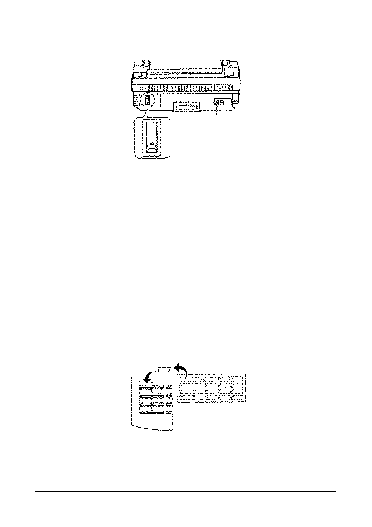
2.3.13 TURNING ON THE POWER
Press the power switch to the up (—) position to turn the power on.
When the fax machine is first powered on, all of the indicators will light and, through the LCD window,
your fax machine will prompt you to wait until the fax machine warms up.
When time and date appears on the window, you can set up the fax machine. This mode is called the
"standby mode."
Pick up the handset and hear a dial tone to be sure the fax machine is properly connected.
Notes:
• When the machine is ready to operate, the user must set current time & date and terminal ID according to
the description in the operating and Installation Manual.
• The fax machine will always set itself to the automatic reception mode (FAX MODE) each time the
machine is powered up. To change the receiving mode, press RCV. MODE. For more information on the
receiving mode, see the operating and installation m manual.
2.3.14 MOUNTING OF THE ADDRESS LABEL
The address label paper is used to make a note of the number when the user stores numbers into one-touch
dialing stations. It will remind the user of what telephone number is stored in each position.
Write information on the label, peel it off, then attach it to the proper position over the corresponding onetouch key as shown below.

2-12
2.3.15 INITIALIZE NEW TONER UNIT
Whenever installing a new toner unit, you must perform the following procedure before operating the fax
machine.
RINGER,TONER OR
SYSTEM SETUP?Y/N
NEW TONER UNIT ?
Y/N
ARE YOU SURE ?
Y/N
NEW TONER UNIT
INITIALIZING...
RINGER.TONER OR
SYSTEM SETUP?Y/N
ADJUST RINGER
VOLUME ? Y/N
ADJUST RINGER
VOLUME ? Y/N
RINGER VOLUME
>>>>>>>>>>
RINGER VOLUME
>>>>>
11
Press FUNCTION, then 7.
2
Press YES.
1
Press FUNCTION, then 7.
2
Press YES.
4
Press YES.
4
The machine displays the current volume scale.
Use SCROLL ¤¤to increase the volume, or SCROLL ˆˆto decrease the
volume.
Each time you press SCROLL ¤¤or SCROLL ˆˆ, the machine sounds a
ring in the loudness you selected.
5
Press YES when a proper volume has been selected. The fax machine
return to the standby mode. If you want to cancel the volume setting,
press STOP.
3
Press NO.
3
Press YES.
5
Press YES when you are sure that you are ready to initialize the toner.
Your fax machine will initialize the new toner unit for a few minutes. The fax
machine is ready for use when the date and time is displayed.
Note: An image quality may be poor when the new drum prints the first 15 sheets;
after that, the image quality will stabilize.
2.3.16 ADJUSTING RINGER VOLUME
You can adjust the volume of the ringer to the desired loudness, if necessary.

2-13
2.4 MEMORY CLEAR
During installation, clear all memory before setting the system data. This sets all function settings to their
initial factory default settings.
1. Press FUNCTION, #, 1, 9, 3, 4 to initiate the tech mode.
In tech-mode, the LCD display shows TECH MODE on the second row of the LCD to indicate that the
machine is operating in the technician mode. The machine will still perform all normal operations while in
this mode.
You must turn the power Off, then turn it on, or press the keys FUNCTION, #, 1, 9, 3, 4 in sequence again
to return from the tech-mode to the user-mode.
2. Press FUNCTION, and 7.
3. Press YES.
4. Press YES again to confirm it.
5. The fax machine clears all memory, then returns to the standby mode.
Print Confirmation Report
You can set the fax machine to automatically print out a Message
Confirmation report every time you send a document. The report shows
whether the transmission was successful or not, how many pages were
sent, etc.
Press YES if you want the report printed out after every document you
send.
Press NO if you do not want the Message Confirmation report.
SET SYSTEM DATA?
Y/N
TO SKIP TO NEXT
PRESS SCROLL V
PRINT MESSAGE
CONFIRMATION?(N)
The currently selected settings are
shown within the parenthesis in
the display.
2.5 SYSTEM DATA SET-UP
There are system data settings that are set by the user in the user-mode, and system data settings set by the
technician in the tech-mode. Before you change the parameter, print the system data list to see the current
setting.
2.5.1 SYSTEM DATA SETTINGS IN USER-MODE
Your fax machine has various user-selectable functions. These functions are usually selected during the
initial setup of the machine, and there should be little need to change them thereafter.
Note: Before you begin, print out the system data list to see the current settings.
11
Press FUNCTION, 0, YES, then NO twice, in sequence.
2
Press YES.
The fax machine will show you the user-selectable functions. Press YES or
NO, or enter the desired number to select proper setting. If you do not
wish to change the option shown in the display, press SCROLL to skip
to the next menu.

2-14
Print Journal Report
You fax machine keeps records of communications. You can get a
transmission or reception journal printout manually or automatically.
Press YES if you want the communication (send and receive) journal
printed out automatically after every 50 transmissions and receptions.
Press NO if you do not want the journal printed out automatically. To
print out the journal manually.
Remote Receive Code
(Used with Extension Telephone)
If you use an extension telephone which is connected to the fax machine,
you can control the fax machine to begin receiving a fax by entering a
remote receive code on the extension telephone.
The code is made up of * 2 *. The first and the last * are fixed, but you can
change the middle digit from 0 to 9. Enter the desired number, then press
YES.
Silence Detection Time
(Used in ANS/FAX mode only)
In ANS/FAX mode, after a call is picked up by the answering machine,
your fax machine monitors the line.
When your fax machine detects a certain time period of silence or that the
line has been released by the answering machine, the call will be treated as
a fax message and your machine can begin to receive a fax.
You can limit the silence detection time to 12 seconds or select unlimited
time.
Press YES if you want to limit the time to 12 seconds.
Press NO if you want to select unlimited silence detection time.
Automatic Turnaround Polling
You can set your fax machine to turnaround poll another machine.
Press YES to poll a remote machine every time you send documents to the
remote machine.
Press NO if you do not want turnaround polling.
If you have selected turnaround polling in Step 7, the fax machine prompts
you to enter a 4-digit turnaround poll code. This code is required to access
a remote fax machine secured with a poll code.
REMOTE RCV CODE?
[0-9]> (*2*)
SILENCE DETECT.
TIME?(UNLIMIT:N)
AUTO TURNAROUND
POLLING ? (N)
TURNAROUND
POLL CODE=0000
AUTO PRINT
JOURNAL ? (Y)

2-15
SAVE END TIME
0900
SAVE START TIME
1700
DIAL MODE?(TONE)
TONE:Y PULSE:N
SECURITY COMM. ?
(N)
SECURITY
CODE = 0000
Power Save Mode
If you want to set your machine to power save mode, press YES.
This setting allows your fax machine to shut off the machine’s printer
heater automatically after a document is printed, and to conserve
electricity and reduce your utility bills. The fax machine automatically
turns on the printer again when it receives a document or is instructed to
make a copy. In the power save mode, it takes the machine a little longer to
print out fax messages or copies, because it must first re-heat the printer.
If you press NO, the machine’s printer heater remains on all the time so
the machine can start printing copies sooner.
If you want to set the time duration that the machine activates the power
save mode, press YES. The machine goes to the power save mode from a
specified start time to a specified end time every day.
If not, press NO. The machine activates the power save mode all the time.
The machine displays the currently selected start time at which the fax
machine goes to the power save mode.
Enter the desired start time using the dial keypad. Use 24-hour format to
select time (Military time).
When the time appears correctly in the display, press YES.
The machine displays the currently selected end time at which the fax
machine exits from the power save mode.
Enter the desired end time using the dial keypad. Use 24-hour format to
select time (Military time).
When the time appears correctly in the display, press YES.
Dial Mode
Select the type of dial mode your fax machine is connected to.
Press YES if the fax machine is connected to a tone dial telephone line.
Press NO if the fax machine is connected to a pulse dial telephone line.
Security Communication (For Msys5700 Only)
The feature allows your fax machine to send and receive documents only to
and from predetermined locations where fax machines have the security
code that matches your security code.
Press YES if you want your fax machine to send or receive documents in the
security communication mode.
Press NO if you want normal communication mode.
If you have selected Security Communication in Step 14, the fax machine
prompts you to enter a 4-digit security code.
The code is used to identify participating stations as members of the closed
network. This ensures only authorized parties can communicate with your
machine.
When the code appears correctly in the display, press YES.
POWER SAVE MODE?
(N)
SET TIME ? Y/N
(17:00→09:00)

2-16
Error Correction Mode
Error Correction Mode (ECM) compensates for poor line quality and
ensures accurate, error-free transmission with any other ECM-equipped
facsimile machine. If the line quality is poor, transmission time may be
increased when ECM is enabled.
Press YES to enable ECM.
Press NO to disable ECM.
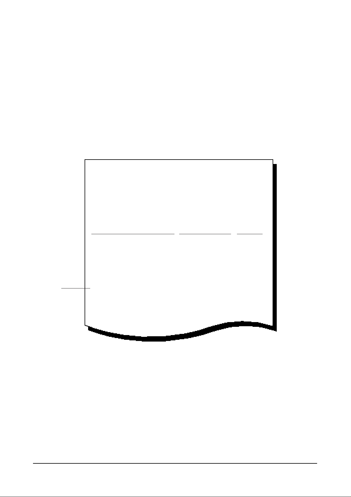
Automatic Reduction
When receiving or copying a document as long as or longer than the paper
installed into your fax machine, the fax machine can reduce the data of the
document to fit on a standard A4 (8.5” x 11”) size paper. The rate of the
reduction is as follows:
If the fax machine can not reduce the data to fit on one page with the
feature enabled, the data is divided and printed out in actual size on two
sheets or more if needed.
Press YES if you want to reduce the incoming page that may need to be
divided into two pages with only a few centimeters on the second page.
Press NO if you do not want to reduce the receiving document. The
overflowed data will be printed out on a second page.
Automatic Discard
When receiving or copying a document as long as or longer than a
standard A4 size paper installed into your fax machine, you can set the fax
machine to discard any excess image at the bottom of the page to fit on a
standard A4 size page.
If the received page is outside the margin you set, it will be printed on two
sheets of paper at the actual size.
If the data is within the margin, and Auto Reduction is turned on, it will be
reduced to fit on the appropriate size paper (Discard does not take place).
If Auto Reduction is turned OFF or fails, the data within the margin will be
discarded.
If the margin is set to 00, a second blank sheet may be printed.
Enter the desired discard size, using the dial keypad, then press YES.
SET DISCARD SIZE
[00 30]> (25)
ECM ENABLE ?
(Y)
AUTO REDUCTION ?
(Y)
Transmitted or
copied document
Printout
Letter size
(8 1/2" x 11")
Reduced
to 95%
→
A4 size
(8 1/4" x 11 11/16")
Reduced
to 89%
→

2-17
Automatic Redial Interval
Your fax machine can automatically redial a remote fax machine if it does not
answer the first call or if it was busy.
Enter the number of minutes (from 0 to 7 minutes), using the dial keypad, to wait
before redialing the number that was busy on the last try. Then press YES.
Note: If you enter 0, the fax machine will not wait. It will redial the number immediately
following the preceding try.
Automatic Redial Number
Enter the number of attempts (from 0 to 7 times) to redial the number before
giving up. Then press YES.
Note: If you enter 0, the fax machine will not redial at all
Ring Before Answer
Enter the number of rings (from 1 to 7) your fax machine should wait before it
answers an incoming call. Then press YES.
If you enter 3, the fax machine will answer calls on the third ring.
To give you time to manually answer your calls when you are present, set this
option for at least four rings.
To return to the standby mode, press STOP.
To verify your setting, print the System Data list.
ANSWER ON NO. OF
RINGS [1-7]> (1)
SET REDIAL INTER
VAL [0-7]> (3)
SET REDIAL
ATTEMPT[0-7]>(3)

2-18
FEATURE
Modem Speed
Error Rate
Tx Level
Cable Select
Receive
Sensitivity
PARAMETER
14400/1200
9600/7200
4800/2400 bps
6%, 12%
0 ~ -15 dBm
0.0 km, 1.8 km
3.6 km, 7.2 km
HIGH/NORMAL
FUNCTION
The maximum TX speed can be limited to 14400(Msys5700),
12000(Msys5700), 9600, 7200, 4800 or 2400 bits per second. when the
TX speed is set to 9600 or 7200 the RX speed can be any V.29 or
V.27ter speed When the TX speed is set to 4800 or 2400, the RX
speed can be any V.27ter speed.
If the error rate exceeds the chosen rate, fall back occurs which will
lower the baud rate automatically down to as low as 2400 baud until
the error rate is less than the chosen rate.
You can set the level of transmission signal. Typically, Tx level
should be under -9 dBm. The level within the range of -9 dBm to -15
dBm is acceptable. Enter the desired value using the dial keypad.
With copper wire, lower frequencies are attenuated less than higher
frequencies. The longer the cable, the more pronounced the effect.
This feature compensates for some loss caused by the cable length.
High sensitivity is between 0 and -40 dBm.
Normal sensitivity is between -5 and -43 dBm.
2.5.2 SYSTEM DATA SETTINGS IN TECH-MODE
Various technical features of fax machine are provided with optional parameters. The chart below shows
you the features and the optional parameters. set the features to the user's need according to the following
procedure.
1 If not in the tech-mode, press FUNCTION, #, 1, 9, 3, 4 in sequence to initiate the tech-mode.
2 Press FUNCTION, 0, YES then NO twice, in sequence.
3 Press YES.
4 Press SCROLL repeatedly until you come to the desired function.
5 When the desired function appears in the display, the technician-selectable parameters are also shown in
the display. Press NO if you do not want the setting shown in the display. The fax machine will display
another parameter you can select one by one each time you press NO. Press YES when the desired
parameter appears in the display.
6 The fax machine will display the next function. To change the parameter, repeat the same procedure
above. To return to the standby mode, press STOP.
2-19
2.6 CONFIRMING SYSTEM DATA SETTINGS
Confirm the system data settings by printing out a system data list.
1. Press FUNCTION, then 6.
2. Press YES.
3. Press NO repeatedly until the fax machine displays "SYSTEM DATA LIST?". Then press YES. The fax
machine prints the system data list. The system data list printed in the tech-mode (Function, #, 1, 9, 3, 4)
contains the system data set in the tech-mode as well as in the user mode.
4. To return to the standby mode, press STOP.
Sample System Data List
NOTE:
If the system data list is printed out in tech-mode (Function, #, 1, 9, 3, 4) the model number and software
version will be printed at the bottom of the system data list.
SYSTEM DATA LIST MAY-10-1998 10:41
FAX NUMBER : 555-1212
NAME : SAMSUNG
CURRENT PRINTED PAGE : 291 PAGE
TOTAL PRINTED PAGE : 1383 PAGE
TONER REPLACE COUNTER : 23
DRUM REPLACE COUNTER : 9
OPTIONS ITEM STATUS
MESSAGE CONFIRMATION REPORT (YES/NO) NO
AUTO PRINT JOURNAL (YES/NO) YES
REMOTE RCV START CODE (0-9) *2*
SILENCE DETECTION TIME (UNLIMITED/12sec) 12sec
AUTO TURN AROUND POLLING (YES/NO) NO
-POLLCODE (¥¥¥¥)
POWER SAVE MODE (YES/NO) YES
-SAVIMG TIME (START END TIME) 16:00 07:00
DIAL MODE (TONE/PULSE) TONE
SECURITY COMMUNICATION
ERROR CORRECTION MODE (YES/NO) YES
AUTO REDUCTION (YES/NO) YES
DISCARD SIZE (00-30) 15 mm
REDIAL INTERVAL (0-7) 3 min
REDIAL ATTEMPT (0-7) 3
Partts in
Msys5700
 Loading...