

Page 1
4-1
Samsung Electronics
4. Troubleshooting
4-1 Preventative Maintenance
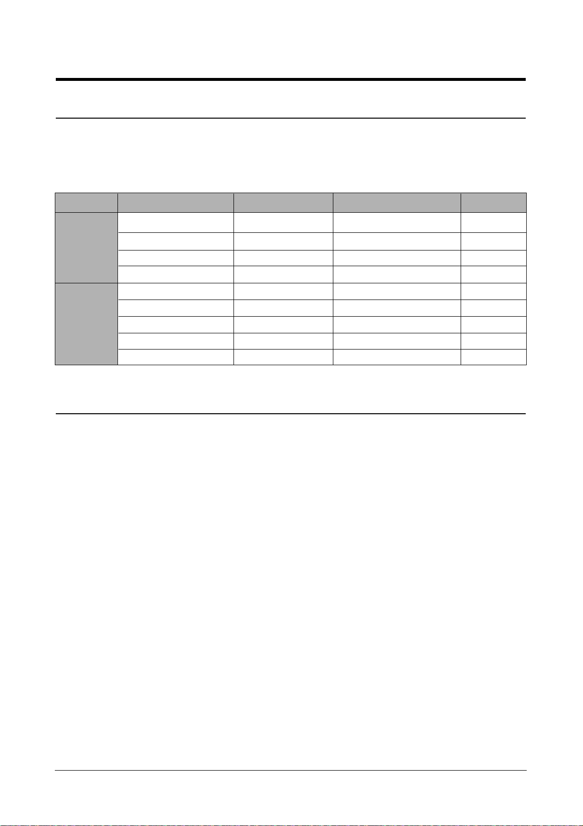
The cycle period outlined below is a general guideline for maintenance. The example list is for an average usage of 50 transmitted and received documents per day.
Environmental conditions and actual use will vary these factors. The cycle period given below is for reference only.
COMPONENT CLEANING CYCLE REPLACEMENT CYCLE SOLUTION
SCANNER
PRINTER
ADF Rubber
ADF Roller
White Roller
CIS
Cartridge
Pickup Roller
Feed Roller
Transfer Roller
Fuser
6 Months
1 Year
As Needed
As Needed
10,000 Pages
20,000 Pages
10,000 Pages
2,500 Pages
60,000 Pages
50,000 Pages
60,000 Pages
50,000 Pages
4-2 Tech Mode
In Tech mode, the technician can perform various tests to isolate the causes of a malfunction, and set the technical option features to customize the machine depending on the user’s operation environment.
To access TECH mode
: Press SETUP, #, 1, 9, 3, 4 in sequence, and the LCD displays ‘TECH’in the standby mode screen. While in TECH mode,
the machine still performs all normal operations.
To return to the normal user mode
: Turn the power off, then back on.
The technical options you have set in TECH mode are not changed unless you clear the machine’s memory in TECH mode.
To communicate via direct connection with another fax machine, press OHD/V.REQ followed by Start/Enter.
• Caution :
When you finish operating in Tech Mode, you must turn the power Off/On.
Page 2

Troubleshooting
4-2
Samsung Electronics
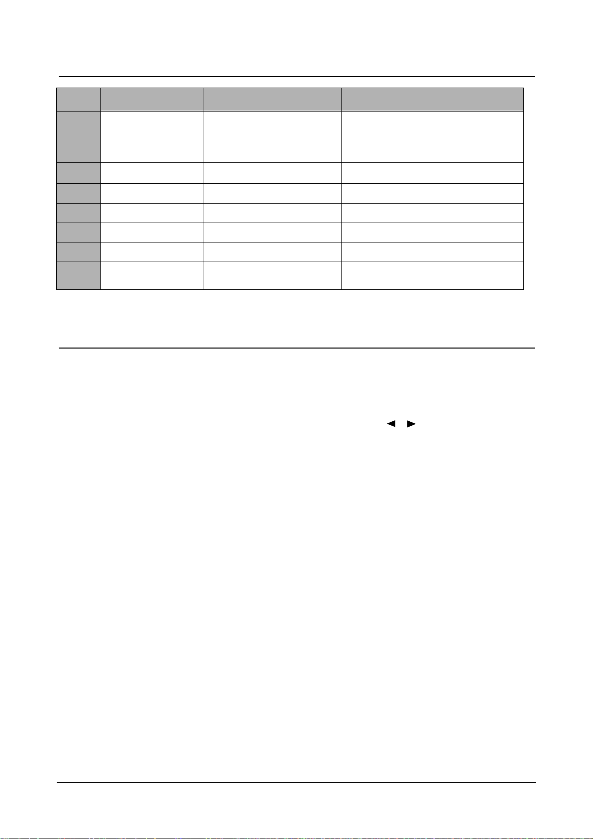
Function Item Content Default
FAX NUMBER/NAME FAX NUMBER
FAX NAME
TIME/DATE SETUP DATE FORMAT EUROPE/USA EUROPE
TIME/DA TE
SYSTEM SETUP LANGUAGE ENG/GER/FRE/ITA/SPA/POR/DUT ENGLISH
SENDING MEMORY ON/OFF ON
SEND FROM CONFIRM ON/OFF/ERROR ERROR
FAX PAPER SIZE LETTER/A4/LEGAL A4
AUTO REDUCTION ON/OFF ON
DISCARD SIZE 0~30mm 20MM
RINGS TO ANSWER 1~7 2
ST AMPRCV .NAME ON/OFF OFF
RCV.START CODE 0~9 * 9 *
ECM MODE ON/OFF ON
CALLER ID ON/OFF OFF
JUNK FAX BARRIER ON/OFF OFF
DRPD MODE ON/OFF OFF
TECH MODE MODEM SPEED 2.4/4.8/7.2/9.6/12.0/14.4/28.8/33.6 26.4 KBPS
DIALING MODE TONE/PULSE TONE
SEND FAX LEVEL 0~15 -12 DBM
RCV. FAX LEVEL 40~50 -43DBM
FLASH TIME(RECALL TIME) 80/280/600 80 MS
P AUSE TIME 1~9 4 SEC
REDIAL INTERVAL 1~15 3 MIN
REDIAL COUNT 0~5 2
DP MAKE/BREAK 40/60~33/67 33/67
SILENCE TIME UNLIMITED/12SEC UNLIMITED
ERROR RATE 5%/10% 10%
IGNORE TONER EMPTY ON/OFF OFF
GROUP DIAL SETUP GROUP NO[1-20]
VOLUM SETUP ALARM VOLUM ON/OFF ON
KEY VOLUM ON/OFF ON
MEMORY CLEAR FAX NUMBER/NAME
DIAL/SCHEDULE
JOURNAL
DEFAULT SETUP
MAINTENANCE CLEANING DRUM
ADJUST SHADING
REMOTE TEST OFF/ON
NOTIFY TONER LOW OFF/ON
ROM TEST ROM OK! (VERSION)
CIS TEST
DRAM TEST DRAM OK
SWITCH TEST
DTMF TEST
TONER COUNT
PRINTING INFO OFF/ON
PROGRAM DOWNLOAD
SCAN COUNT CLEAR COUNT CLEARING .
4-2-1 System Data List in TECH MODE
: Only Tech Mode
Page 3

Troubleshooting
4-3
Samsung Electronics
In TECH mode, press SETUP, then press or until
‘TECH MODE’ appears in the display. Press Start/Enter.
The following technical options are available.
Note : If necessary, print System Data List in TECH mode.
The list shows all current system data settings
including the TECH MODE options. To print the system data list, press Report/Help, then press
or until ‘SYSTEM DATA ’appears in the dis-
play, and press Start/Enter.
Modem Speed
• You can set the maximum modem speed.
• Communication is done with modem speed automatically
set at lower speed when communicating with the modem
with lower speed since communication is done on the standard of the side where modem speed is low for transmission/reception. It is better set 26.4KBPS as default setting.
DIALING MODE
• Select the dialing mode according to the user's line status.
• TONE: Electrical type of dial
• PULSE: Mechanical type of dial
SEND FAX LEVEL
• You can set the level of the transmission signal. Typically,
the Tx level should be under -12 dBm. The level within the
range of 1 to -15 dBm is acceptable.
• Caution: The Send Fax Level is set at the best condition
in the shipment from factory. Never change settings arbitrarily.
RCV FAX LEVEL
• You can set the level of the receiving signal.
•
The reception level may be too low due to the cable losses.
• If it is set to -43 dBm, the reception sensitivity will be
between 0 and -43 dBm. If it is set to -48 dBm, the reception sensitivity will be between 0 and -48 dBm.
• Caution: The Send Fax Level is set at the best condition
in the shipment from factory. Never change settings arbitrarily.
FLASH TIME
• Set the flash time to 80, 280, or 600 milliseconds.
PAUSE TIME
• Pause time mean delay time (unit: second) inserted
between dial number signal and the next number of signal
in the automatic dial (One touch, Speed dial, Redial) and
the manual dial.
• Caution: The Send Fax Level is set at the best condition
in the shipment from factory. Never change settings arbitrarily.
REDIAL INTERV AL
• If the remote machine is busy when the machine sends a
fax using automatic dialing, the machine automatically
redials the number. Select the time interval between automatic redial attempts. Enter the desired redial interval
using the number keypad: 1 - 15 minutes.
REDIAL COUNT
• You can set times that redial automatically attempts when
automatic transmission is done or when the remote
machine is busy or when the machine send a fax. If there
is no response after redialing by the times already set,
redial is no longer attempted. No redial is attempted if the
settings is 0. Enter the desired times from 1 through 5.
DP Make/Break
• Select the dial pulse make and break time: 40-60 or 33-67
• Caution: Send Fax Level is set at the best condition in the ship-
ment from factory. Never change settings arbitrarily.
SILENCE TIME
• In ANS/F AX mode, after a call is picked up by the answer ing machine, the machine monitors the line.
• If a period of silence is detected on the line at any time, the
call will be treated as a fax message and the machine
begins receiving.
• Silence detection time is selectable between limited (about
12 seconds) and unlimited time.
• When '2 sec' is selected, the machine switches to receiving mode as soon as it detects a period of silence. When
'unlimited'is selected, the machine waits until the answering operation is concluded even though a period of silence
is detected. After the answering operation is concluded,
the machine switches to receiving mode.
ERROR RATE
• When the error rate is about to be over the setting value,
the Baud rate automatically lowers up to 2400 bps to make
the error rate remain below the setting value.
• You can select the rate between 5% and 10%.
IGNORE TONER EMP
• You can set this function ON if desiring to drive the engine
continuously even though the life of toner is run out and it
becomes Toner Empty status.
4-2-2 Tech Mode Options
Page 4

Troubleshooting
4-4
Samsung Electronics
In TECH mode, press SETUP, then press or until
‘MAINTENANCE’ appears in the display. Press Start/Enter.
The following technical options are available
CLEAN DRUM
• Use this feature to get rid of the toner remained in the
development unit, so you can get a clean printout.Perform
this feature if stains or specks appear on the printing materials and print quality falls.
• Perform this feature several times until a clean printing
material appears.
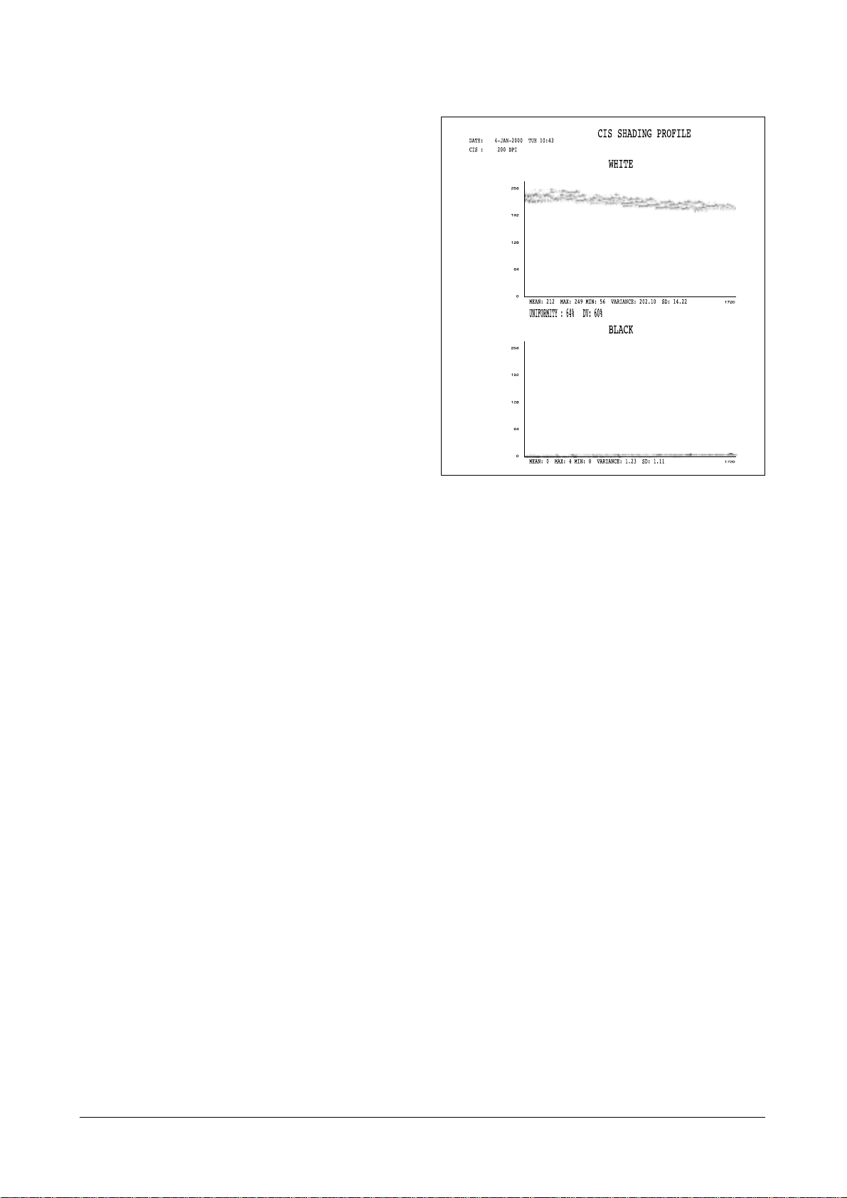
ADJUST SHADING
• Use this feature to correct the white reference of the scanner if you experience bad copy images. When using this
feature, a white paper should be used to get clean copy
images.
• Use this adjustment feature to achieve best image (scan)
quality depending on the characteristics of the CIS (Contact
Image Sensor) parts.
1. Select [ADJUST SHADING] from the Service Mode.
2. Insert a clean white original [Letter Size] into the paper
loading part.
3. Original is scanned if pressing the Setting button.
4. If the original scan is completed, message is displayed
on the LCD window and CIS SHADING PROFILE is
output.
• If the output image is different from the normal screen, the
CIS is poor.
Caution:
1. Always perform the CIS TEST after downloading
Firmware. Otherwise, the system may not operate properly .
2. Always perform ADJUST SHADING after replacing the
CIS.
3. Always use a clean white paper in ADJUST SHADING
(Maximum paper width: Letter Size).
4. ADJUST SHADING may be performed even in the User
Mode but ADJUST SHADING profile is output only in the
TECH MODE.
REMOTE TEST
• The Remote Test feature can be enabled in order to allow
a remote location to call up and run a diagnostic test on
your machine. You may be instructed by a service representative to enable this feature.
NOTIFY TONER LOW
• With this feature enabled, when the toner becomes low, the
toner low information will be sent to ta specified contact
point, for example, the service company. After you access
this menu, select ON, and when the LCD prompts, enter
the name and the number of the contact point, the customer's fax number, the model name, and the serial number.
ROM TEST
• Use this feature to test the machine'S ROM. The result and
the software version appear in the LCD display.
CIS TEST
• This test checks the operation of the Contact Image Sensor
(CIS). Each time the number changes by one increment,
the average ADC value of CIS prints out.
DRAM TEST
• Use this feature to test the machine's DRAM. The result
appears in the LCD display.
SWITCH TEST
Use this feature to test all keys on the operation control
panel. The result is displayed on the LCD window each time
you press a key.
MODEM TEST
• Use this feature to hear various transmission signals to the
telephone line from the modem and to check the modem.
• If no transmission signal sound is heard, it means that the
modem part of the main board is poor.
DTMF TEST
• DTMF (Dual Tone Multi Frequency) signal. When you
press any key on the number keypad including • and #, you
will hear the corresponding key tone.
TONER COUNT
•This feature shows the current state of the toner cartridge.
•TONER CNT: The total number of the dots used to print up
to current time.
•CRU STATE: The page number which the toner cartridge
can print.
• Caution : After replacing Main board to new one, you
should update the information to the new board.
4-2-3 Maintenance Options
Page 5
Troubleshooting
4-5
Samsung Electronics
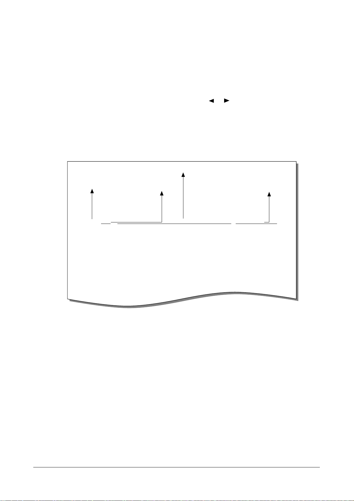
PRINTING INFO
• This feature allows the machine to automatically print various information, like toner count, transfer voltage, fusing
temperature and so on, at the bottom of each printed page.
• PAGE T ONER CNT: prints the number of dots used to print
the page.
• TOTAL TONER CNT: prints the total number of the dots
used to print up to current time.
• THV ON DUTY: prints ADC value of transfer voltage.
• THERMISTER: prints ADC value of fusing temperature.
• P: prints the page number.
PROGRAM DOWNLOAD
• Use this feature to download a new upgraded ROM file
from a PC that is connected to the machine with a parallel
cable (IEEE 1284).
SCAN COUNT CLEAR
• If performing this feature, the value of scanning original until
now is initialized (0). (Total scan count value on the system
data list becomes 0.)
Adjust Shading Sample Pattern
Page 6

Troubleshooting
4-6
Samsung Electronics
In TECH mode, press Report/Help, then select the desired
list or report by using or key, then press Start/Enter.
The following options are available
HELP
• It shows a brief description on the machine's basic functions and commands.Use it as a quick reference guide
SENT JOURNAL
• This journal shows a specific information concerning transmission activities, the time and dates of up to 40 of the
most recent transmissions.
RECEIVED JOURNAL
• This journal shows a specific information concerning
reception activities, the time and dates of up to 40 of the
most recent receptions.
PHONEBOOK
• It lists all telephone numbers that have been stored in the
machine.
SENDING CONFIRM
• It shows the result of the last send operation.
SCHEDULE INFORM
• This list shows a specific information on the documents
currently stored for delayed transmission. It provides the
operation number, starting time, type of operation, etc.
SYSTEM DATA
• This list provides a list of the user system data settings and
tech mode settings.
PROTOCOL LIST
• This list shows the sequence of the CCITT group 3 T.30
protocol during the most recent sending or receiving operation. Use this list to check for send and receive errors. If
a communication error occurs while the machine is in
TECH mode, the protocol list will print automatically.
PATTERN PRINT
• Using this pattern printout, you can check if the printer
mechanism is functioning properly. Examine the pattern
and look for a break in the diagonal line. If the diagonal
lines are not broken, the printer mechanism is functioning
properly .
SHADING PRIN
• With this print, you can check the scanning elements of the
CIS (Contact Image Sensor).
The Engine test mode is used to check the operation of the
components related to the printer engine.
The following test are available.
To access the Engine Test Mode:
1. Press Setup, #, 1, 9, 3, 1 in sequence.
2. When ‘ENGINE TEST?’ appears, press Start/Enter.
3. Scroll the options by pressing or repeatedly find
the one you want.
4. Press Start/Enter to start the test.
5. Press Stop to exit the Engine test mode.
• Caution :
When you finish operating in Engine Test Mode, you must turn
the power Off/On.
Engine Test Mode Options :
1. MAIN MOTOR TEST
2 PTL TEST
3. FAN TEST
4. FUSER TEST
( FUSER ON : 145˚C , FUSER OFF : 145˚C )
5. LSU MOTOR TEST
6. LD(LASER DIODE) TEST
7. HSYNC TEST (NG/OK)
8. LSU OPERATION TEST (NG/OK)
9.
SENSOR TEST ( FEED , EXIT , PAPER EMPTY , COVER OPEN)
10. SOLENOID TEST
11. MHV TEST( -1550 V )
12. DEV TEST ( - 430 V )
13. THV(+) TEST ( +1300 V )
14. THV(-) TEST
15. THV TRIGGER TEST
16. ALL FUNCTION TEST :
This function is for a manufacturing press . You can test
all function(1~15)
• When you push the “Start” button, the Main Motor runs.
• If you push the “Start” button again , the current test
stops, and the next test starts.
4-2-4 Printout Report
4-2-5 Engine Test Mode
Page 7
S NSF 61005820003380140200001302090018010000
S/R FCF FIF DATA ASCII
S CSI 2020202020202020202020202O20202020202020
S CSI 202020202020202020202022O202020220202020
R TSI 2020202020202020202020202O20202020202020
S DIS 00000000 01110111 00010111 00100010
S DIS 00000000 01110111 00010111 00100010
R DCS 00000000 01100001 00010101 00000000
R TSI 2020202020202020202020202O20202020202020
R DCS 00000000 01100001 00010101 00000000
S CFR
R MPS
S MCF
S DCN
S FTT
S NSF 61005020003380140200001302090018010000
PROTOCOL DUMP LIST OCT-20-1999 06:35
Sending/Receiving
Name of signal
(Facsimile Control Field)
Facsimile Information Field
data described in hexdecmal code
FIF data described
in ASCII code
Troubleshooting
4-7
Samsung Electronics
< SAMPLE OF APROTOCOL DUMP LIST >
A number of reports can be printed from the fax machine
within the test mode. The protocol list all contain detailed
information which may be required when contacting technical support.
To printout the protocol list :
1. Get into the Tech mode by pressing Setup, #, 1, 9, 3, 4.
2. In Tech mode, press Report/Help.
3. Press or repeatedly until you find the Protocol
List. When you find ‘PROTOCOL LIST’, press ENTER.
SAMPLE OF APROTOCOLDUMP LIST
4-2-6 Maintenance List
Page 8

Troubleshooting
4-8
Samsung Electronics
4-3 Diagnostics
This section describes methods and procedures to isolate the cause of a malfunction in the machine. This machine displays diagnostic information on the LCD. In addition, it can perform a series of tests that allow the machine to observe individual machine
functions.
4-3-1 Error Messages
DOCUMENT JAM
DOOR OPEN
LINE ERROR
LOAD DOCUMENT
LSU ERROR
The loaded document has jammed in the feeder. Clear the document jam.
The top cover is not securely latched. Press down on the cover until it clicks in
place.
Your unit cannot connect with the remote
machine, or has lost contact because of a problem on the phone line.
Try again. If failure persists, wait an hour
or so for the line to clear, then try again.
Or, turn the ECM mode on.
You have attempted to set up a sending operation with no document loaded.
Load a document and try again.
There occurs a problem in the LSU
(Laser Scanning Unit).
Unplug the power code and plug it back
in. If the problem still persists, please call
for service.
FUSER ERROR
There occurs a problem in the fuser unit.
Unplug the power code and plug it back
in. If the problem still persists, please call
for service.
MEMORY FULL
The memory is full. Either delete unnecessary documents, or
retransmit after more memory becomes
available, or split the transmission into
more than one operation.
JAM/NO CARTRIDGE
Recording paper has jammed inside the unit, or
the toner cartridge is not installed.
Clear the jam, or install the cartridge
NO ANSWER
The remote machine has not answered after all
the redial attempts.
Try again. Make sure the remote machine
is operational.
NO. NOTASSIGNED
The one-touch or speed dial location you tried
to use has no number assigned to it.
Dial the number manually with the keypad, or assign a number.
Error Message Description Solution
Page 9

Troubleshooting
4-9
Samsung Electronics
NO PAPER
OVER HEAT
POLLING ERROR
POWER FAILURE
RECEIVE ERROR
The recording paper has run out. Load the recording paper.
The printer part in your unit has overheated. Please wait until it cools down.
If you cannot solve the problem, please
call for service.
The remote fax machine you want to poll is not
ready to respond to your poll.
Or When setting up to poll another fax machine,
you have used an incorrect poll code.
The remote operator should know in
advance that you are polling and have
their fax unit loaded with the original document. Enter the correct poll code.
A power failure has occurred. If documents have been stored in the
memory, a ‘Power Failure Report’ will be
printed automatically when the power is
restored.
A fax has not been received successfully. A problem with the facsmile communica-
tions has occurred. Ask the sender to try
again.
PAPER JAM 0
Recording paper has jammed in the paper feeding area.
Clear the jam.
RETRY REDIAL ?
The machine is waiting for a specified time interval to redial a previously busy station.
You can press Start to immediately redial, or Stop to cancel the redial operation.
PAPER JAM 2
Jammed paper still remains inside the unit.
Clear the jam, or install the cartridge
SEND ERROR
Your fax has not gone through successfully. A problem with the facsmile communica-
tions has occurred. Try again.
TONER EMPTY
TONER LOW
WARMING UP
The toner cartridge has run out. The machine
stops.
The toner is almost empty.
The printer is warming up and is off-line.
Replace with a new toner cartridge.
Take out the toner cartridge and gently
shake it. Using this way, you can temporarily re-establish the print quality.
Wait until the printer is on-line.
Error Message Description Solution
Page 10
Troubleshooting
4-10
Samsung Electronics
When you replace the main board to new one, the information on the toner state is cleared. Therefore, you should
update the information to the new board by entering the
exact value of total toner count and specifying the toner cartridge installed currently is shipped with the machine or new.
If not, ‘TONER LOW/EMPTY’ message may not appear
when the toner is run out.
1. In Tech mode, print ‘SYSTEM DATA LIST’. The list
includes the total toner count and CRU state information.
• TOTAL TONER COUNT: The total number of the dots
used to print up to current time.
• CRU STATE: The page number which the toner cartridge can print. (The yield of a new toner cartridge is
approximately 2,500 pages and that of the cartridge
supplied with the machine is approximately 1.000
pages.)
2. Replace Main board.
3. In Tech mode,
3-1) Press Setup, and find ‘MAINTENANCE’ by pressing
repeatedly or , then press Start/Enter.
3-2) When ‘TONER COUNT’ is displayed in LCD, press
Start/Enter, and enter the value of the total toner
count in the system data list.
3-3) When you are prompted to enter CRU STATE, press
Start/Enter.
3-4) When you see ‘[1.1000 2.2300]’ in LCD, select the
value of the CRU state in the system data list.
4. In T ech mode, print ‘SYSTEM DAT ALIST’and make sure
that the toner information is updated.
4-4 Print Quality
4-5 Note for replacing Main board
No Roller Abnormal image period Kind of abnormal image
1 OPC Drum 75.4mm •White spot on black image
•Black spot
2 Charge Roller 37.7mm Black spot
3 Supply Roller 26.8mm Horizontal density band
4 Develope Roller 31.6mm Horizontal density band
5 Transfer Roller 47.1mm Black side contamination/transfer fault
6 Heat Roller 50.1mm Black spot, White spot
7 Pressure Roller 50.2mm Black side contamination
Page 11

Troubleshooting
4-11
Samsung Electronics
Vertical black line and band
YES
NO
YES
OK after
replacing the LSU?
Remove part on the paper
path causing the trouble
NO
OK after replacing
developer?
Any obstacles on
the developer blocking
the laser beam.
OK after
removing the
obstacles?
Any obstacles ON
mirror lens of LSU and
laser path?
Remove the obstacles.
Replace the LSU
Replace the developer
END
YES
YES
YES
NO
NO
NO
4-6 Troubleshooting Flow Chart
Page 12

Troubleshooting
4-12
Samsung Electronics
Check connection to
computer or replace
controller
Take out the cartridge
and prepare the tester
for electronic connection
Repair or replace the GND
terminal
Check the path between
video controller, engine board
and HVPS. Repair or replace
the defective component
or board
The mirror in LSU might be
misplaced so the light path to the
OPC deviates ->Repair or replace
LSU or remove any deffective
matters in the machine
Self test
pattern prints?
No image?
Self testing
is possible via
Tech Mode?
Is the OPC
terminal of machine
is well-connected
to Frame?
Does the
video data line to
LSU transit to High/Low
when printing?
Re-test after replacing the
conector or Main board
A on
next page
NO
NO
NO
NO
NO
YES
YES
YES
YES
YES
No Image
Page 13

Troubleshooting
4-13
Samsung Electronics
Transfer roller might be out of its location
-> Locate the roller into its place
This could occurrs when he power of LSU is low or
the density is low due to the obstacles on the window
-> Replace LSU or clean the window
A
Trnasfer
voltage OK? (on the
transfer roller
shaft)
Is the
connection of
OPC GND and Frame Ground
correct? (less than
10 ‰)
Are the
connection terminal
and connection
correct?
Repair or replace terminal
Replace HVPS or repair defective component
Is the connection
terminal OK?
Check the connection of
frame Ground and OPC GND
Replace HVPS or repair defective component
Repair or replace terminal
Developing
(-350V) and supplying
(-550V) voltage
are OK?
Does the
counter indicate over
the toner’s guarranty
life
Replace the toner cartridge
NO
NO
NO
NO
NO
YES
YES
YES
YES
YES
YES
Page 14

Troubleshooting
4-14
Samsung Electronics
Replace the developer
NO
YES
YES
END
YESYES
NO
NO
NO
YES
YES
NO
Replace the HVPS
Ok after setting to the
normal mode?
YES
NO
Remove the obstacles
NO
YES
Clean transfer roller
and gear holder
YES
NO
Replace the LSU
Replace the developer
Is it not over
the guaranty life of dot
counter?
Is the toner save
mode or the light mode
is selected?
Is the high voltage
normal? (charging,
developing,
transfer)
Any obstacles on the
gab between high voltage
terminal and
developer?
Transfer roller
works OK?
OK after replacing
LSU?
HVPS works OK?
Light image
Page 15

Troubleshooting
4-15
Samsung Electronics
All black in
printing area?
Is transfer
voltage supplied
(-1.55 KV)?
Is the
Hsync/ signal received
in LSU?
Transfer part’s contact
is bad -> Repair or
replace toner cartridge
Does the
video data line to LSU
transit to High/Low when
printing?
Replace LSU
Check the path among video
controller, engine board,
HVPS, LSU for the shortage
or open -> Repair or replace
the boards
Repair or replace HVPS
Replace LSU
NO
NO
NO
NO
YES
YES
YES
YES
All Black
Page 16

Troubleshooting
4-16
Samsung Electronics
White line
missing definitely?
Dirt of dust stuck onto the window of internal
lens of LSU
-> Clean it or replace LSU
Preventive obstacles through the path between
OPC of developer and LSU prevent the path
-> Remove the obstacles
Check if the
printout is still has the
same problem even right after
passed through the
transfer roller
Toner material might be stuck to blade in the developer
inside and it prevents toner supply
-> Replace the toner cartridge
Check both if the toner cartridge’s counter is over its
guaranty and amount of the toner material
-> Replace the toner cartridge
The ribs in fuser or toner on the roller may invoke
the image problem
-> Replace the fuser cover or the defective part
The image is originally black or the black part is
far close to the top
-> Use the pattern which has the image below bigger
than 10mm from the top
NO
NO
END
NO
YES
Does the problem
persist?
YES
YES
Vertical White Line (Band)
Page 17

Troubleshooting
4-17
Samsung Electronics
Dark selected
via RCP?
Change to
Normal and test
Works cor
with -350V of Bias
voltage?
Works
correctly after
replaced LSU?
Repair or replace the defective
component
The power of LSU is set
high or internal problem
-> Replace LSU or adjust
voluem
Same at Normal?
END
NO
NO
NO
Toner over supply due to the
adjustment fault of metering
blade in developer
-> Replace developer
NO
YES
YES
YES
YES
Dark Image
Page 18

Troubleshooting
4-18
Samsung Electronics
Recommended
paper used?
Is pressure of
transfer roller too high?
Does the operation of
TR work properly?
Transfer,
charge and developing
voltage are OK?
Operating/
storage atmosphere is
too high temperature
/humidity?
Solve the problem under
the recommended condition
(10-32 degree Centigrade)
Dirt or
dust around the
charge roller?
Clean the charge roller
or replace step-up device
/terminal after check
Work OK?
Internal blade or suppying
part of the developer is
defective
-> Replace the toner cartridge
Check Terminals or contacts and ’Guide-Deve Spring’
are misplaced
-> Repair or replace transfer roller etc.
Print 20 to 30 pages using
the recommended paper
Same problem
occurs?
- Adjust voltage or replace HVPS
- Repair or replace after checking the
terminals’ contacts
Replace transfer
roller’s holder
END
Replace the
toner cartridge
NO
NO
NO
NO
NO
NO
NO
YES
YES
YES
YES
YES
YES
YES
Background
Page 19

Troubleshooting
4-19
Samsung Electronics
Is it regular
interval of 75.4mm?
Irregularity of NIP
between rollers in
developer
-> Replace developer
Clean heat roller
or replace it
Clean transfer roller’s holder and
TR drive gearor replace TR holder ass’y
Clean TR drive
and OPC gear
END
A specific part of the transfer roller has
ruined or its resistance value is changed
-> Replace transfer roller
Transfer roller cannot force regularly due
to the gears eccentricity of transfer roller
-> Replace the defective component
Adjust the Bias
voltage or replace HVPS
There may be a problem in toner
layer control in toner cartridge
-> Replace the developer
Use the machine with
recommended paper and
at condition
NO
NO
NO
NO
NO
NO
YES
YES
YES
YES
YES
YES
NO
YES
YES
YES
YES
Check HVPS
contacts and
HVPS’s self-output
-> If failed, repair/
replace HVPS
- Repair or replace HVPS
- Check and Repair or
replace the terminal
contacts
NO
NO
Is it regular
interval of 31.6mm?
Is it regular
interval of 47mm?
(as transfer roller
interval)
Is it regular interval of
50.4 mm?
Does
the operation
of TR work properly?
Transfer
voltage is set to
standard?
Does the same
problem persist?
Developing
/suppying voltage
normal? (-350V/
-550V)
Bias voltage
is OK? (-350V)
Operating/storage
temperature is too low or
not recommended
paper used?
Ghost
Page 20

Troubleshooting
4-20
Samsung Electronics
The problem occured
since the obstacles
stuck to charge roller
-> Replace toner cartridge
When taking
out the cartridge,
toner leaks?
Toner leaks and toner
material dropped onto
the paper -> Replace the
developer
Bad image
removes by
scratching?
Check toner is stuck onto
the P/R or H/R in fuser
-> Clean it or replace
The problem
randomly occured
due to the toner
fallen -> Clean the
machine
Remove obstacles
stuck on OPC
drum’s surface
Perform the OPC
cleaning using
the control panel
buttons.
END
NO
YES
NO
NO
YES
NO
YES
Does the same
problesm
persist?
Is it regular
interval of 37.7mm?
Is it regular
interval of 75.4 mm?
NO
YES
YES
Black Spot
Page 21

Troubleshooting
4-21
Samsung Electronics
NO
Black band?
The black
band has regular
interval?
Black band
is far about 10mm from
white band?
Problem of internal
contacts in OPC
-> Replace developer
The OPC is damaged under the
direct sunlight for around 5
minutes -> If the same problem
persists in 10 hours, replace
the developer
This occurs when no
Hsync/ at LSU
-> Replace LSU
75.4 mm interval?
Heat roller is ruined
-> Replace the roller
The OPC is damaged due to
the irregular transfer voltage
of HVPS
-> Repair/replace HVPS
-> If the same problem persists,
replace the developer
Does it appear
at every 56.1mm at
specific place?
Problems of terminal contact,
transfer voltage supplying,
and transfer roller’s due to the
charge roller is ruined (37.7mm)
-> Repair/replace HVPS,
developer
NO
NO NO
NO
YES
YES
YES
YES
Horizontal Band
Page 22

Troubleshooting
4-22
Samsung Electronics
Transfer roller
is clear ?
Clean the transfer roller
NO
YES
Paper path is
clear ?
Clean the paper path
Clean the pressure roller
NO
YES
Toner Contaminations on Back of Paper
Page 23

Troubleshooting
4-23
Samsung Electronics
Is it not over
the guaranty life of dot
counter?
Replace the toner cartridge
NO
YES
YES
YES
Is toner cartridge
installed correctly?
Install the toner cartridge correctly
NO
Transfer roller
works properly?
Clean the TR holder, the TR gear,
OPC roller gear and the transfer roller
NO
- Clean the contact point of transfer roller
- Check the output of high voltage terminal
and adjust or replace if required
Partial Blank Image (not Periodic)
Page 24

Troubleshooting
4-24
Samsung Electronics
Is it not over
the guaranty life of dot
counter?
Replace the toner cartridge
NO
YES
YES
NO
NO
Is toner
cartridge installed
correctly?
Install the toner cartridge
correctly
NO
Is it regular
interval of 47.1mm?
Transfer roller
works properly?
OK after
replacing the transfer
roller?
Is it regular
interval of 75.4mm, 31.6mm
or 37.7mm?
Replace the fuser
(50.2mm, 45.2mm or exit roller
- Clean the contact point of
transfer roller.
- Check the output of high
voltage terminal and adjust or
replace if required.
Replace the toner cartidge
END
YES
YES
NO
YES
NO
YES
Clean the TR holder, the TR
gear OPC roller gear and the
transfer roller
Partial Blank Image (Periodic)
Page 25

Troubleshooting
4-25
Samsung Electronics
It is over the guaranty
life of toner cartridge
(Check the counter
and replace it)
Defective agitator in
the toner supplying part
of developer
->Replace the developer
Check if the ’guide deve
spring’ works OK and
repair/repalce
Check high voltage
output and repair/
replace terminals, HVPS
Irregualrity of toner
suppy from developer
-> Repalce developer
Light distortion due to
the mirror ruined or
LSU’s diffused reflection
-> Replace LSU
NO
NO
YES
YES
YES
YES
NO NO
OK after
taking out and
rocking the toner
cartridge?
When gray
pattern printing,
irregular density
persists?
transfer/
charge/developing
voltage drops while
printing?
Bad images
aroung the no image
area?
Irregular Density
Page 26

Troubleshooting
4-26
Samsung Electronics
Is it regular
interval of 75.4mm?
Obstacles stuck on OPC’s
surface
-> Clean the OPC and
machine or replace
developer
When putting in/out the
developer, scratch is made
-> Replace the developer
Transfer
voltage is normal?
D/R in developing unit has
the defect
-> Replace the developer
Too high voltage supplied
due to the setting error of
transfer voltage
-> Adjust/replace HVPS
NO
NO
YES
YES
White Spot
Page 27

Troubleshooting
4-27
Samsung Electronics
When multi-page OHP printng,
less than 10 films are
guranteed.
Use the recommended film
When OHP
printing, does the fan
temporarily stops
and revolves?
Use the recommended film
Other parts are touching the
fan and prevents it from
revolution
-> Check and repair
NO
NO NO
YES
Set to OHP mode
NO
YES
YES YES
Is the OPC
mode selected using
the software
application?
Recommended
OHP film used?
Inserted over
than 10 films into
the MPF?
Trembling at the End When OHP Printing
Page 28

Troubleshooting
4-28
Samsung Electronics
After printing
completed, any error
related fuser?
Both ends
of thermostat
open?
Replace thermostat
and re-test
Replace the contol
component on engine
board
Check any contact
problem in thermistor
and repair
The machine
placed under the
severe low tempera
ture for a long
time?
Place the machine
at normal
temperature and
re-test
While printing,
the voltage of pin 208
of U5 (CPU) on Main
board is 2.0V
~2.3V?
Thermistor’s
contact is OK?
Open the top
cover. When black
printing, is the fuser NIP
width is 1.2~
3.0mm?
The paper used is too
thick or contains too
much cotton in it
-> Re-test with the
recommended paper
Check if the hardness of
P/R, and spring force is OK?
(spring’s force: 2.5 Kg)
Re-assemble
thermistor
NO
NO
NO
NO
NO
NO
YES
YES
YES
YES
YES
YES
Poor Fusing Grade
Page 29

Troubleshooting
4-29
Samsung Electronics
Plug in the
power cord?
The power
voltage supplying is
the same as
rating?
The fan
revolves when
powered on?
LEDs blink
once when
powered on?
The On-Line
key is being pressed
or shortage on
the panel
board?
Repair/replace the
board
Check the voltage first and plug
the power cord
Supply the power as the rating
Connections
on board are OK?
Re-connect firmly
and re-test
The connection
error between
controller board
and panel board
or malfunction
of boards.
-> Replace the
boards
Fuse of SMPS
if open?
Shortage
between 5V and
GND, or between
24V and
GND?
Replace the fuse
Toner cartridge
is in the set?
Detect failure due to the
board which detects top
cover open or switch error
-> Replace the board or switch
Put in the
cartridge
Remove the shortage
or replace the board
NO
NO
NO
NO
NO
NO
NO NO
NO
YES
YES
YES
YES
YES
YES
YES
YES
YES
No Power (LCD NO display LED Off)
Page 30

Troubleshooting
4-30
Samsung Electronics
Less than 10W?
AC is being supplied?
The voltage
of pin #208 of U5
(CPU) on the Main board
is about 2.3V when
printing?
END
Thermostat is open due to the heat etc.
-> Replace the thermostat
Check the PCI and fusing
control part and CN502
on the SMPS
-> Replace the component
or replace the SMPS
Measure the resistance
at the both ends of AC
Line with covers open
Remove the covers
Re-assemble the top
cover and close it
Thermistor, connecting point or engine
board defect -> Repair/replace the
component/board
NO
NO
NO
YES
YES
YES
Fuser Error
Page 31

Troubleshooting
4-31
Samsung Electronics
Sounds the
solenoid on when starts
print?
Does the
paper move?
Does the
paper move more than
100mm?
The Engine board defected
-> Replace boards
The solenoid defected
-> Replace it
The pick-up unit is
assembled wrong
-> Re-assemble or replace
the unit
Feeder
sensor and paper
width detect sensor
are assembled
reverse?
Switch them
The Sensor board
defected
-> Repair/replace
Too many
papers in the
feeder?
Paper guides
fit the paper width?
Paper end curled?
Does the
extender pulled out?
<Recommendation>
Use the MPF for the thick
paper such as envelope
and cardstock
Reduce the amount
and re-test
Take out the paper
and re-insert
Use the recommended
and quality paper
Pull out the
extender
NO
NO
NO
NO
NO
NO
NO
YES
YES
YES
YES
YES
YES
YES YES
Paper Jam (Mis-feeding)
Page 32

Troubleshooting
4-32
Samsung Electronics
Paper
stopped before
the OPC?
Check the LSU and
if it has the defect
replace it
Paper
stopped before
the fuser?
Severe skew
when feeding?
Adjust the paper guides to fit the
paper width
The force of springs pressing the
developer is weak
-> Check guide-DEVE
The paper
came out through
between fuser and
developer?
Too thin
or sensitive paper to
static electricity?
Use the recommended
paper
Check guide transfer
is grounded Check
the shutter prevents
feeding
Check the input path
to the fuser (such as
mis-assembly)
The
actuator of
paper exit sensor
works OK?
Check the actuator exists and its
operation and around the engine board
-> Replace
Is the paper
rolled around the
presseure
roller?
Remove the fuser, remove
the paper and replace the
pressure roller, if necessary
Feeds
multiple pages?
Remove any factors
Check the roller
and ribs of fuser
are in place, and
remove burrs, if
any
-> Remove the
factors of jam
NO NO NO
NO
NO
NO
NO
NO
YES
YES
YES
YES
YES
YES
YES
YES
Paper Jam (Jam1)
Page 33

Troubleshooting
4-33
Samsung Electronics
Try again to connector
or
Replace connector
END
NO
Check
CBF Harness28P
(MAIN B’D to ENGINE
B’D)
YES
Check
MAIN B’D CN9-6,
HSYNC Signal
( )
Replace LSU
NO
YES
Check
MAIN B’D CN9-3,
P_MOTOR Signal
( )
Replace MAIN B’D
NO
YES
Check
MAIN B’D CN9-4,
LREDADY Signal
( )
Replace LSU
NO
YES
Check
MAIN B’D CN9-9,
LDON Signal
( )
Replace MAIN B’D
NO
YES
LSU Error
 Loading...