

Page 1
3-1
Samsung Electronics
3. Disassembly and Reassembly
3-1 General Precautions on Disassembly
When you disassemble and reassemble components, you must use extreme caution. The close
proximity of cables to moving parts makes proper
routing a must.
If components are removed, any cables disturbed
by the procedure must be restored as close as
possible to their original positions. Before removing
any component from the machine, note the cable
routing that will be affected.
Whenever servicing the machine, you must perform as follows:
1. Check to verify that documents are not stored in
memory.
2. Be sure to remove the toner cartridge before you
disassemble parts.
3. Unplug the power cord.
4. Use a flat and clean surface.
5. Replace only with authorized components.
6. Do not force plastic-material components.
7. Make sure all components are in their proper
position.
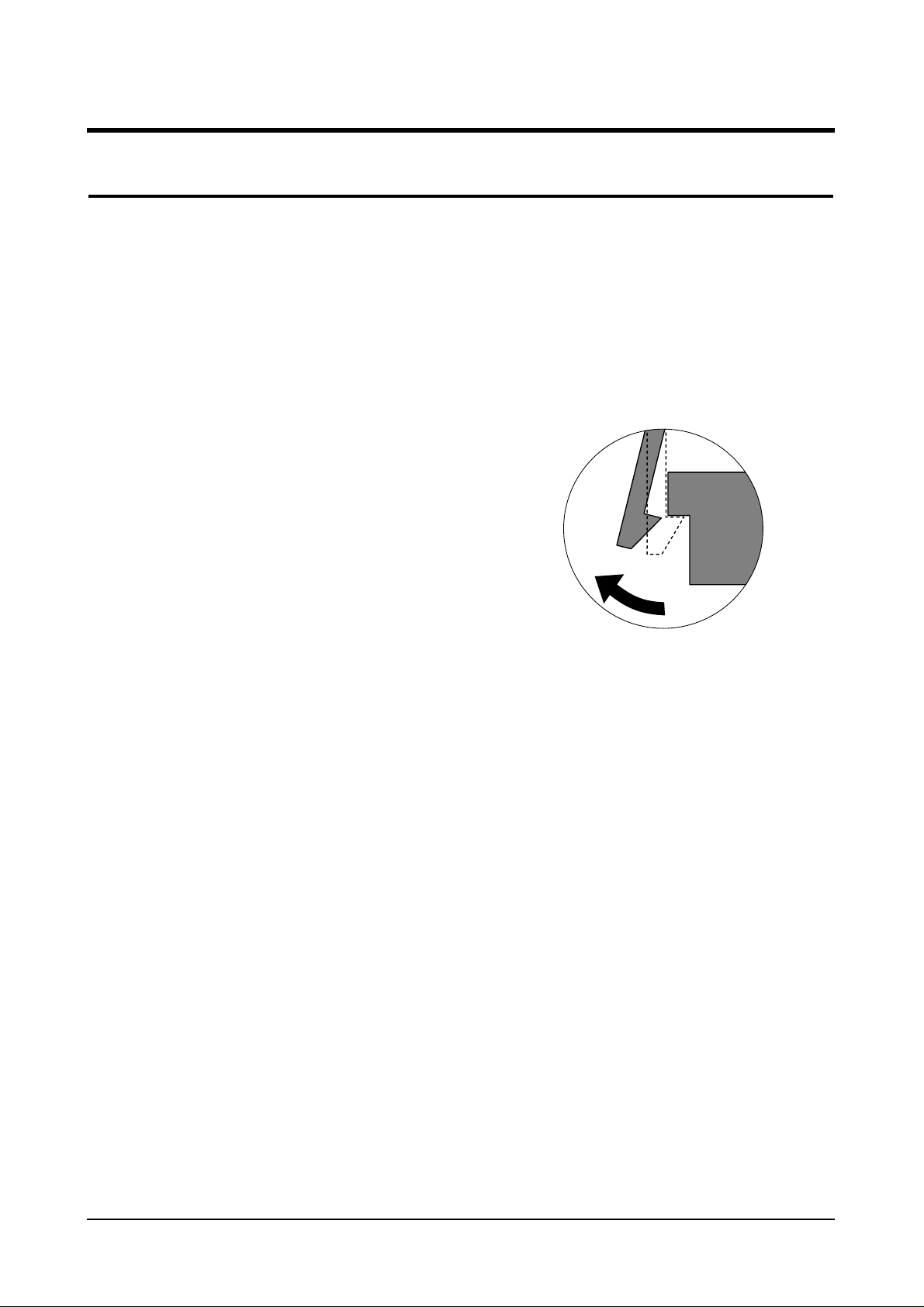
Releasing Plastic Latches
Many of the parts are held in place with plastic
latches. The latches break easily; release them
carefully.
To remove such parts, press the hook end of the
latch away from the part to which it is latched.
Page 2
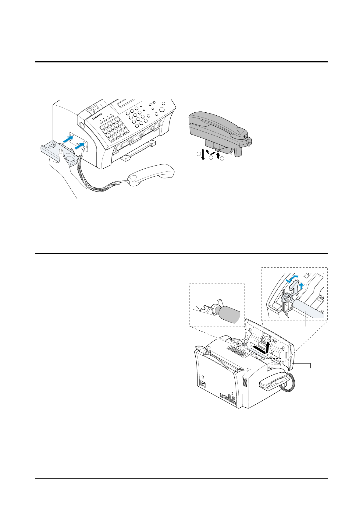
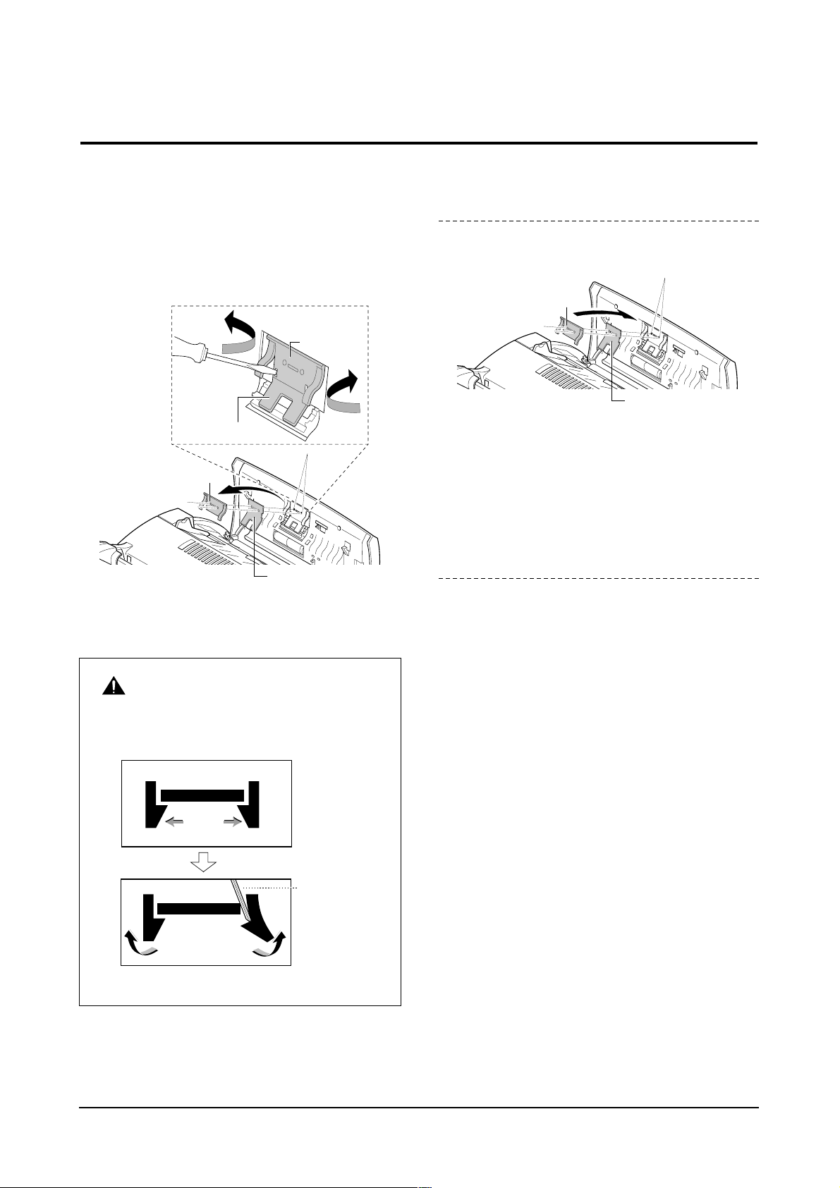
3-2 Cradle
1. Push the lever and remove the cradle as shown
below.
3-3 White Roller
1. Open the OPE cover.
2. Push the bushing on the end of the Roller slightly
inward, then rotate it until it reaches the slot.
Then lift, the Roller out.
Note : Check the Roller for any dirt. If dirty, wipe it off with
soft cloth dampened with water. If the Roller is
heavily worn, replace it with a new one.
3-2
Samsung Electronics
Disassembly and Reassembly
0
0
0
0
0
0
0
0
0
0
0
0
0
0
0
0
0
0
0
0
0
0
0
0
0
0
0
0
0
0
0
0
0
0
0
0
0
0
0
0
0
0
0
0
0
0
0
0
0
0
0
0
0
0
0
0
0
0
0
0
0
0
0
0
0
0
0
0
0
0
0
0
0
0
0
0
0
0
0
0
0
0
0
0
0
0
0
0
0
0
0
0
0
0
0
0
0
0
0
0
0
0
0
0
0
0
0
0
0
0
0
0
0
0
0
0
0
0
0
0
0
0
0
0
0
0
0
0
0
0
0
0
0
0
1
2
3
Control Panel
Bushing
White Roller
A
B
Page 3
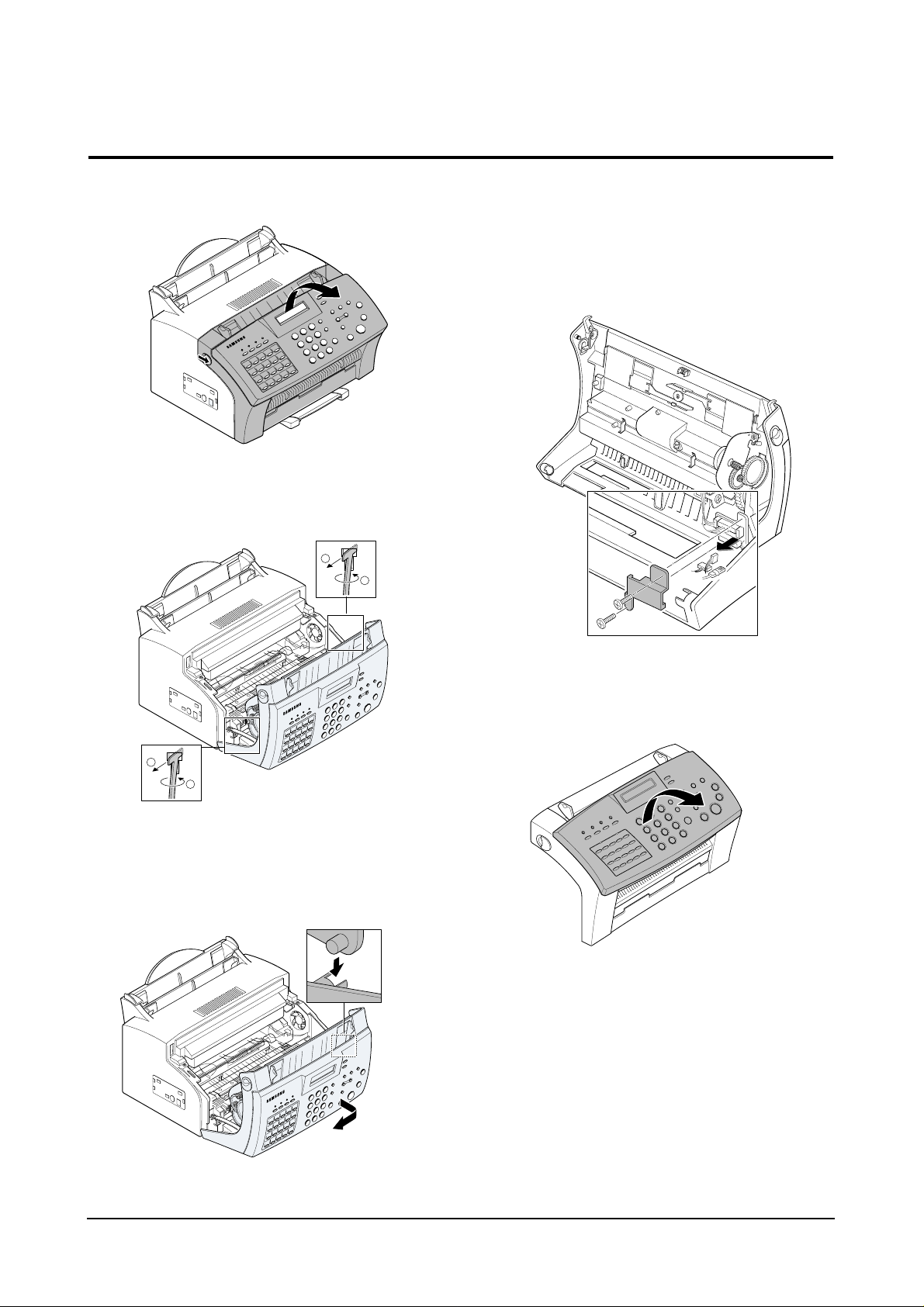
3-4 OPE Cover
1. Pull the cover release button on both sides of the
machine, and open the front cover.
2. Remove two stoppers holding the front cover unit and
unplug one connector and one wire.
3. Pull the bottom left end of the cover downward to
unlatch the front cover unit and remove the cover
from the main frame.
4. Remove two screws securing bracket scan board,
then take out the bracket scan board.
5. Unplug two connectors and one wire from the scan
board.
6. Lift the OPE cover.
Samsung Electronics
3-3
Disassembly and Reassembly
1
2
1
2
Page 4
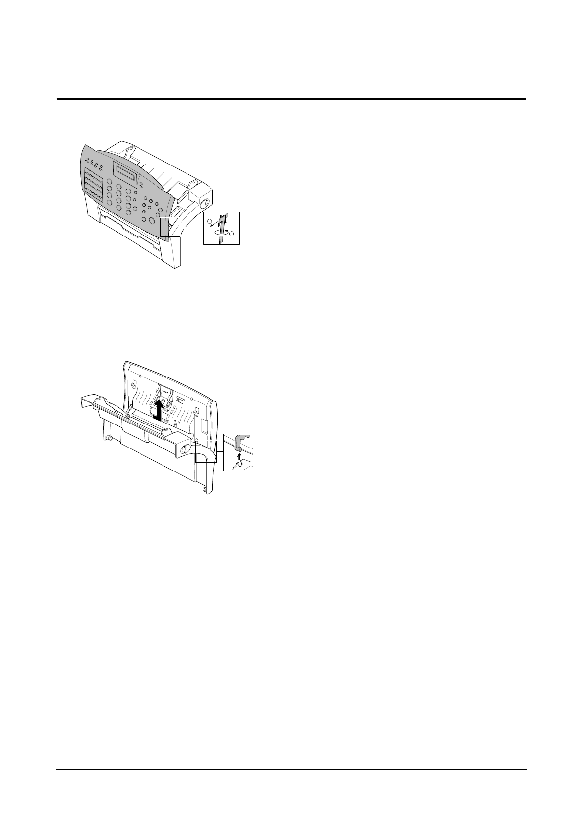
7. Remove the stopper holding the OPE cover.
8. Unlatch the bottom ends, then remove the OPE
cover.
3-4
Samsung Electronics
Disassembly and Reassembly
1
2
Page 5
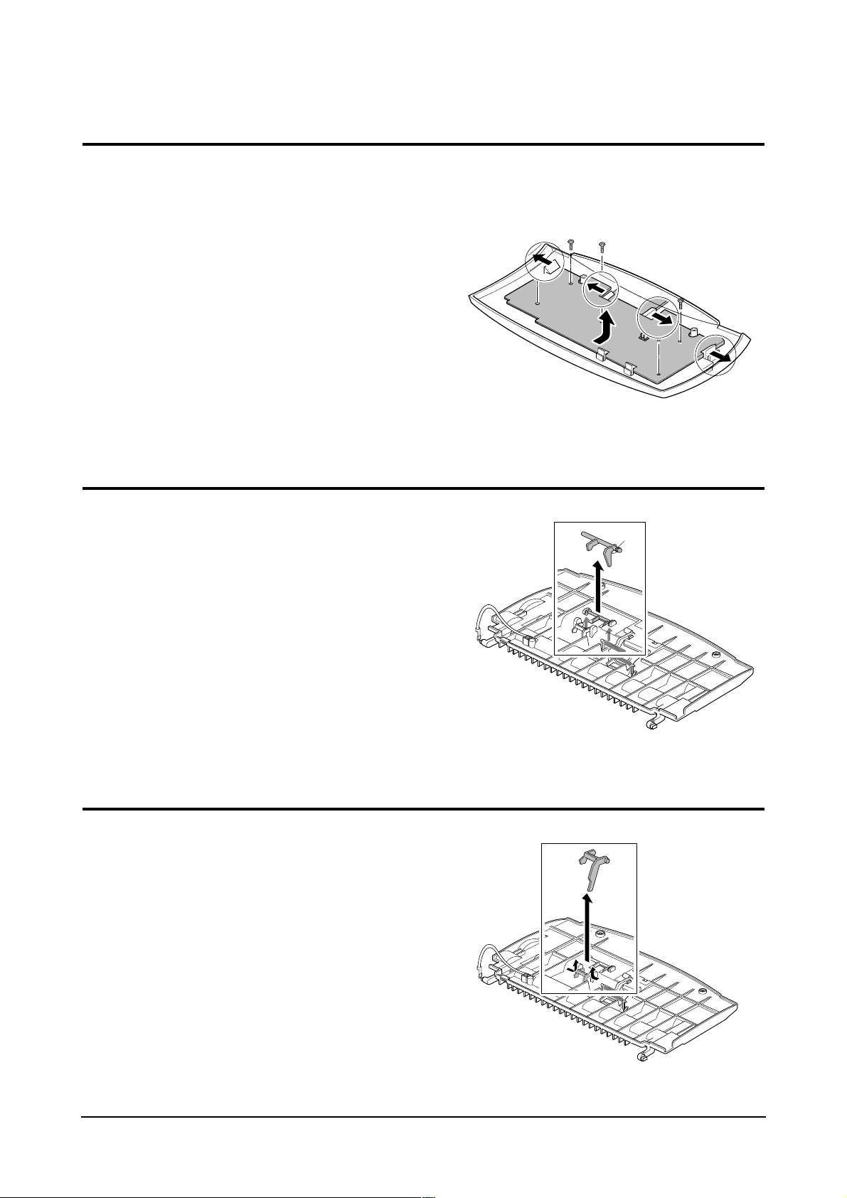
3-5 ADF Rubber
1. Open the OPE unit.
2. Insert a flat blade screw driver and pinset into the slot
as shown below, and release the latches. Take out the
Holder Rubber, Sheet ADF and the Rubber ADF.
Notes : • When you reassemble the them, be sure that
the Rubber ADF and Holder Rubber fit into the
guide boss and the Holder Rubber latches fit
into the corresponding hole. Then push firmly
until it clicks.
3. Clean the surface of the rubber pad with IPA(Isopropyl
Alcohol). After wiping it, be sure to dry it. Check the rub ber wear. If the wear reaches 1/2 its original thickness,
replace it with a new one.
Samsung Electronics
3-5
Disassembly and Reassembly
Holder Rubber
Rubber ADF
Guide Boss
Holder Rubber
Rubber ADF
Pinset or
Screw Driver
Safely Precautions :
Do not force to open or fasten plastic material
components.
Rubber ADF
Guide Boss
Holder Rubber
Page 6
3-6 OPE Board
1. Before you remove the OPE board, you should
remove:
– OPE cover (see page 3-3)
2. Remove four screws securing the OPE board.
3. Release two latches securing the both side of the
LCD and the two of four latches securing the board.
Then remove the OPE board.
3-6
Samsung Electronics
Disassembly and Reassembly
3-7 Lever Sensor Doc.
1. Unlatch the lever sensor Doc from the scan upper
frame and take it out.
3-8 Lever Sensor Scan
1. Push the both sides of Lever sensor Scan inward,
then unlatch and take out the sensor Scan from the
scan upper frame.
Page 7
3-9 Scan Board
1. Before you remove Scan board, you should remove:
– Bracket scam board (see page 3-3)
2. Unplug all the connectors from the scan board and
remove the board.
Samsung Electronics
3-7
Disassembly and Reassembly
3-10 Scan Motor
1. Before you disassemble Scan Motor , you should
remove:
– OPE cover (see page 3-3)
– Bracket scan board (see page 3-3)
2. Unplug one connector from the scan board.
3. Remove three screws, then remove the motor Ass’y
from the main frame.
4. Take out the gear from the Motor Ass’y.
5. Remove two screws and remove the motor.
Page 8
3-11 ADF Roller
1. Before you remove the ADF Roller, you should
remove:
– OPE cover (see page 3-3)
2. Remove two screws securing the guide paper and
remove the guide paper.
3. Remove ADF Roller from the scan front frame.
3-8
Samsung Electronics
Disassembly and Reassembly
Guide Paper
ADF Roller
3-12 CIS
1. Remove one screw and push CIS as shown below
and lift it.
2. Separate the Dummy CIS from CIS.
CIS
tape
Page 9

3-13 Rear Cover
1. Remove two screws.
2. Push the metal clip on the parallel port down and
remove the rear cover from the main frame.
Samsung Electronics
3-9
Disassembly and Reassembly
3-14 Top Cover
1. Before you remove the ADF Roller, you should
remove:
– OPE cover (see page 3-3)
– Rear cover (see above)
2. Remove two screws securing the top cover from the
back side of the machine.
3. Remove two screws and slide the left and right paper
guides fully inward. Then spread the bottom of the top
cover and lift the cover to remove.
Paper guides
Page 10

3-15 Tray
1. Before you remove the tray, you should remove:
– OPE cover (see page 3-3)
– Rear cover (see page 3-9)
– Top cover (see page 3-9)
2. Take out the tray from the main frame.
3-10
Samsung Electronics
Disassembly and Reassembly
3-16 LSU
1. Before you remove the LSU, you should remove:
– All covers (see page 3-3, 3-9)
2. Remove three screws securing the LSU.
3. Unplug two connectors from the LSU and remove the
LSU.
Page 11

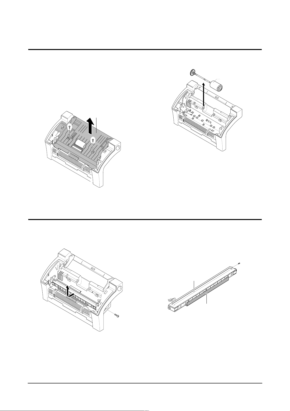
3-17 Transfer Roller
1. Pull the cover release button on both sides of the
machine, and open the front cover.
2. Lift the transfer Roller using a proper tool (-Driver) and
take out the Roller.
Samsung Electronics
3-11
Disassembly and Reassembly
3-18 Engine Board
1. Before you remove the Engine board, you should
remove:
– All covers (see page 3-3, 3-9)
– LSU (see page 3-10)
2. Unplug five connectors and remove one screw from
the engine board, then remove the board.
Page 12

3-19 Pick-up Roller Ass’y
1. Before you remove the pick-up Roller Ass’y, you
should remove:
– All covers (see page 3-3, 3-9)
– LSU (see page 3-10)
2. Unplug all the connectors from the engine board.
3. Remove four screws securing the plate upper and
remove the plate upper as below.
4. Remove two screws and remove the Roller from the
plate.
Note : When you reassemble the pick-up Roller, make
sure that the right end of the pick-up Roller fits
into the pick-up gear shaft.
3-12
Samsung Electronics
Disassembly and Reassembly
Pick-up gear shaft
Page 13

3-20 Knock-up Ass’y
1. Before you remove the knock-up Ass’y, you should
remove:
– All covers (see page 3-3, 3-9)
– LSU (see page 3-10)
– Plate upper (see page 3-12)
2. Pull the knock-up Ass’y fully backward.
3. Remove the knock-up Ass’y from the main frame.
Samsung Electronics
3-13
Disassembly and Reassembly
3-21 Cap-Pad
1. Before you remove the cap-pad, you should remove:
– All covers (see page 3-3, 3-5)
– LSU (see page 3-10)
– Plate upper (see page 3-12)
– Knock-up Ass’y (see above)
2. Take out the cap-pad from the main frame.
Page 14

3-22 Holder-Pad
1. Before you remove the holder-pad, you should
remove:
– All covers (see page 3-3, 3-9)
– LSU (see page 3-10)
– Plate upper (see page 3-12)
– Knock-up Ass’y (see 3-13)
– Cap-Pad (see 3-13)
2. Remove the holder-pad from the main frame.
3-14
Samsung Electronics
Disassembly and Reassembly
3-23 Motor Ass’y
1. Before you remove the motor Ass’y, you should
remove:
– All covers (see page 3-3, 3-9)
2. Remove four screws securing the motor Ass’y and
unplug one connector from the engine board, then
remove the motor Ass’y.
Note : When you reassemble the motor Ass’y, make
sure that the boss shown in the figure below fit
into the corresponding screw holes on the motor
Ass’y to allow the screws to be fastened properly.
Boss
Page 15

3-24 Fan
1. Before you remove the fan, you should remove:
– All covers (see page 3-0)
– Motor Ass’y (see page 3-15)
2. Unplug one connector from the engine board and
remove the fan.
Samsung Electronics
3-15
Disassembly and Reassembly
3-25 Gear pick-up Ass’y
1. Before you remove the gear pick-up Ass’y, you
should remove:
– All covers (see page 3-3, 3-9)
Note: When reassembling, make sure that the direction
of the gear is correct.
2. Release two snap-fits and remove the gear pick-up
Ass’y from the main frame.
Page 16

3-26 Solenoid
1. Before you remove the solenoid, you should remove:
– All covers (see page 3-3, 3-9)
2. Unplug one connector from the engine board and
remove one screw, then remove the solenoid.
3-16
Samsung Electronics
Disassembly and Reassembly
3-27 HVPS Board
1. Before you remove the HVPS board, you should
remove:
– All covers (see page 3-3, 3-9)
2. Remove three screws and one connector from the
HVPS board, then remove the board.
Note : when reassembling, make sure that the terminal
is five.
Page 17

3-28 Hook Board
1. Before you remove the hook board, you should
remove:
– All covers (see page 3-3, 3-9)
2. Unplug one connector from the main board and
remove two screws, then remove the hook board from
the main frame.
Samsung Electronics
3-17
Disassembly and Reassembly
3-29 Fuser Ass’y
1. Before you remove the fuser Ass’y, you should
remove:
– All covers (see page 3-3, 3-9)
2. Remove two wires after remove two screws from the
main frame and one connector from the inter connector.
3. Remove two screws and unlatch the fuser Ass’y using
a proper tool.
Page 18

3-30 Thermostat
1. Remove one screw and remove the cover thermostat
from the fuser Ass’y.
2. Remove two screws and take out thermostat from the
fuser Ass’y .
3-18
Samsung Electronics
Disassembly and Reassembly
3-31 Halogen Lamp
1. Before you remove the thermostat, you should
remove:
– All covers (see page 3-3, 3-9)
– Fuser Ass’y (see page 3-17)
2. On the fuser Ass’y, remove the two screws, then
remove the heat Roller.
3. Remove the halogen lamp from the heat Roller.
Page 19

3-32 Pressure Roller
1. Before you remove the pressure Roller, you should
remove:
– All covers (see page 3-3, 3-9)
– Fuser Ass’y (see page 3-17)
2. Lift and remove the pressure Roller from the main
frame.
Samsung Electronics
3-19
Disassembly and Reassembly
3-33 Actuator-Exit
1. Before you remove the actuator-exit, you should
remove:
– All covers (see page 3-3, 3-9)
– Fuser Ass’y (see page 3-17)
2. Lift and remove the actuator-exit from the main
frame.
Page 20

3-34 SMPS Board
1. Before you remove the SMPS board, you should
remove:
– Rear cover (see page 3-9)
– Shield Engine Ass’y (see page 3-19)
2. Remove four screws and three connectors, then
remove the SMPS board from the main frame.
3-20
Samsung Electronics
Disassembly and Reassembly
3-34 Shield Engine Ass’y
1. Before you remove the shield engine Ass’y, you
should remove:
– Rear cover (see page 3-9)
2. Remove eight screws securing the shield engine
Ass’y and remove the shield engine Ass’y from the
main frame.
Page 21

Samsung Electronics
3-21
Disassembly and Reassembly
3-36 Speaker
1. Before you remove the speaker, you should remove:
– Rear cover (see page 3-9)
– Shield Engine Ass’y (see page 3-19)
– SMPS board (see above)
2. Remove one connector that connects the speaker to
the main board and two screws securing the speaker,
then remove the speaker.
3-37 LIU Board
1. Before you remove the LIU board, you should
remove:
– Rear cover (see page 3-9)
– Shield Engine Ass’y (see page 3-19)
2. Remove three screws and three connectors from the
LIU board, then remove the board from the main
frame.
Page 22

3-39 Sensor Board
1. Before you remove the sensor board, you should
remove:
– Rear cover (see page 3-9)
– Shield Engine Ass’y (see page 3-19)
2. Release four snap-fits securing the sensor board and
unplug one connector from the main board, then
remove the sensor board.
3-22
Samsung Electronics
Disassembly and Reassembly
3-38 Main Board
1. Before you remove the main board, you should
remove:
– Rear cover (see page 3-9)
– Shield Engine Ass’y (see page 3-19)
2. Remove four screws and all the connectors (9) from
the main board, then remove the board.
Page 23

Samsung Electronics
3-23
Disassembly and Reassembly
3-40 Actuator Empty/Feeder
1. Before you remove the actuator empty/feeder, you
should remove:
– Rear cover (see page 3-9)
– Shield Engine Ass’y (see page 3-19)
2. Remove one connector from the main board and two
screws securing the holder feed Ass’y, then remove
the holder feeder Ass’y.
3. Remove the Feed sensor and the Empty sensor.
Feed Sensor
Empty Sensor
Page 24

3-24
Samsung Electronics
Disassembly and Reassembly
3-41 Roller Feeder
1. Before you remove the actuator empty/feeder, you
should remove:
– All covers (see page 3-0)
– Motor Ass’y (see page 3-15)
2. Release two snap-fits and remove the gear-feed,
clutch-feed, and the spring-clutch.
3. Rotate the pick-up bushing as shown below and
remove holder feeder Ass’y and Roller feeder.
4. Separate the Roller Feeder from the Holder Feeder
Ass’y .
Spring-clutch
Clutch-feed
Gear-feed
Roller Feed
Holder Feed
 Loading...