

Page 1
3. Disassembly
3-1. General Precautions on Disassembly
When disassemble and reassembling components, use extreme caution. The close proximity of cables to moving
parts makes proper routing a must. If components are removed or replaced, any cables
disturbed by the procedure must be replaced as close as possible to their original positions. Before removing
any component from the machine, note the cable routing that will be affected.
Whenever servicing the machine, you must perform the following:
1. Check that documents are not stored in memory.
2. Remove the print cartridge.
3. Unplug the power cord.
4. Work on a flat and clean surface.
5. Replace only with authorized components.
6. Do not force plastic components.
7. Make sure all components are in their proper position.
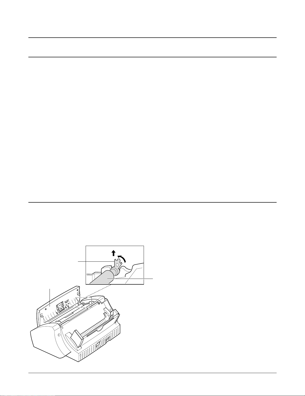
3-2. White Roller
1. Lift the control panel.
2. Push the white clip on each end of the roller
slightly inward, then rotate it until it reaches the
slot, as shown below. Then lift the roller out.
B
white clip
Control panel
A
Note : Check the roller for dirt. If dirty, wipe it off
with soft cloth dampened with water. If the
roller is heavily worn, replace it with a new
one.
White roller
Samsung Electronics 3-1
Page 2

Disassembly
3-3. Rear Cover
1. Holding the paper guide, move it in the direction
of arrow.
Paper guide
3. Holding the rear cover ass’y, take it out by
rotating it to release properly.
2. Remove the six screws, as shown below.
3-2 Samsung Electronics
Page 3

3-4. Top Cover and Speaker
Disassembly
1. Before you disassemble the top cover, you should
remove:
– Rear Cover (see page 6-2)
2. Remove the handset, and unplug the connector
from the main board.
4. Remove the four screws securing the cover.
3. Release the tie stopper supporting the control
panel.
Tie stopper
5. If you want to remove the speaker, turn the top
cover over, and remove the two screws securing
it.
3-3Samsung Electronics
Page 4

Disassembly
3-5. Scan Motor
1. Before disassembling the scan motor, you should
remove:
– Rear Cover (see page 6-2)
– Top Cover (see page 6-3)
2. Unplug the motor connector from the main
board. Make sure the harness is released from the
two hooks, as shown below.
4. Remove the ground plate.
3. Remove the two screws as shown below.
Ground plate
5. Remove the ground screw securing the motor to
the motor bracket.
3-4 Samsung Electronics
Page 5

3-6. ADF Roller and Contact Image Sensor (CIS)
Disassembly
1. Before disassembling the roller and CIS, you
should remove:
– Rear Cover (see page 6-2)
– Top Cover (see page 6-3)
2. Remove the ADF roller. When you assemble the
roller, make sure it is properly hooked.
3. Unplug the CIS harness, then remove the CIS
ass’y. To remove the CIS ass’y, turn it up and
slide the two legs far left, and pull it up.
Note : Clean the surface of the roller with ethyl
alcohol. After wiping it, you must dry it
completely.
4. Remove the CIS from the bracket.
CIS
Note: Check the glassy surface of the CIS for stains
or scratches. If stained, wipe off with ethyl
alcohol. If it is heavily scratched, replace it
with a new one.
Samsung Electronics 3-5
Page 6

Disassembly
3-7. SMPS
1. Before disassembling the SMPS, you should
remove:
– Rear Cover (see page 6-2)
2. Unplug the SMPS connector from the main
board. Make sure the harness is released from the
hook.
3. Remove the two ground screws from the bracket,
as shown.
4. Pushing down the hook, as shown in the inset,
remove the SMPS.
3-6 Samsung Electronics
Page 7

3-8. LIU Board
Disassembly
1. Before disassembling the board, you should
remove:
– Rear Cover (see page 6-2)
– Top Cover (see page 6-3)
2. Remove the screw securing the ground wires to
the SMPS bracket.
3. Pulling the snaps locking the board outward,
remove the board.
Snap fit
4. Unplug all the connectors from the board.
Samsung Electronics 3-7
Page 8

Disassembly
3-9. Buzzer and Hook Board
3-9-1. Buzzer
1. Before disassembling the buzzer, you should
remove:
– Rear Cover (see page 6-2)
– Top Cover (see page 6-3)
2. Unplug the connector from the LIU board, and
remove the buzzer.
3-9-2. Hook Board
1. Before disassembling the board, you should
remove:
– Rear Cover (see page 6-2)
– Top Cover (see page 6-3)
2. Unplug the connector from the LIU board.
3. Remove the screw, then remove the board.
3-8 Samsung Electronics
Page 9

3-10. OPE Unit
Disassembly
3-10-1. ADF Rubber Pad
1. Open the control panel.
2. Insert a flat blade screw driver into the slot as
shown below, and remove the rubber holder and
the rubber pad.
Rubber holder
Rubber pad
3-10-2. OPE Unit
1. Before disassembling the OPE unit, you should
remove:
– Dummy ASF (see page 6-2)
– Rear Cover (see page 6-2)
– Top Cover (see page 6-3)
– LIU Board (see page 6-7)
2. Unplug the connector from the main board, and
pull up the OPE unit.
Notes:
• When reassembling the rubber pad, be sure that it
and the holder fit into the guide boss and the
holder latches fit into the corresponding hole.
Then push firmly until it clicks.
• Clean the surface of the rubber pad with ethyl
alcohol. After wiping, be sure to dry it. Check for
rubber wear. If the wear reaches 1/2 its original
thickness, replace it with a new one.
3. Remove the two screws and remove the cover.
Samsung Electronics 3-9
Page 10

Disassembly
4. Remove the microphone (SF3000T only) and the
seven screws.
Microphone
(SF3000T only)
Notes:
• Do not turn the OPE unit upside down after you
remove the screws securing the board. Keys and
rubber contacts may be separated and easily lost.
• When reassembling the OPE unit, make sure the
keys are in correct position.
• When reassembling the board, secure the screws
according to the order printed on the PBA.
• After reassembling, operate the machine to make
sure it works properly.
• After reassembling, make sure the LCD is not
blocked.
5. Remove the OPE board. Then remove the two
screws from the LCD and remove the LCD.
LCD
3-10 Samsung Electronics
Page 11

3-11. Printer Unit
Disassembly
1. Before disassembling the printer unit, you should
remove:
– Dummy ASF (see page 6-2)
– Rear Cover (see page 6-2)
– Top Cover (see page 6-3)
2. Slide the cartridge carrier, as shown below.
3. Remove the two screws securing the printer unit,
and unplug the six connectors from the main
board.
The connectors are located as shown below. It is
not necessary to unplug the LF motor connector
to remove the printer unit.
LF motor
4. Remove the printer unit. When you pull up
printer unit, be careful to properly release the
harnesses.
Samsung Electronics 3-11
Page 12

Disassembly
3-12. ASF Feeder
1. Before disassembling the ASF feeder ass’y, you
should remove:
– Dummy ASF (see page 6-2)
– Rear Cover (see page 6-2)
2. Remove the two screws securing the ASF feeder.
4. Remove the screw securing the pickup shaft. To
remove the pickup shaft, pull it to the far right
and take it out.
Pickup shaft
3. Unlock the ASF feeder assembly, and remove it.
Note : When reassembling the ASF feeder ass’y,
insure the harness for the line feed motor is
not pinched or shorted.
3-12 Samsung Electronics
Page 13

3-13. Printer Unit Miscellaneous
Disassembly
3-13-1. Cartridge Carrier Home Assembly
1. Before disassembling the cartridge carrier home,
you should remove:
– Dummy ASF (see page 6-2)
– Rear Cover (see page 6-2)
– Top Cover (see page 6-3)
– Printer Unit (see page 6-11)
2. Remove the screw securing the cartridge carrier
home, and take it out.
3-13-2. Cartridge Carrier Assembly
1. Before disassembling the cartridge carrier
assembly, you should remove:
– Dummy ASF (see page 6-2)
– Rear Cover (see page 6-2)
– Top Cover (see page 6-3)
– Printer Unit (see page 6-11)
– Cartridge Carrier Home Assembly
(see page left)
– ASF Feeder (see page 6-12)
– Main Board (see page 6-15)
2. Remove the cable holder, and remove the screw
on the right side of the frame.
Carrier shaft
Carrier
Holder
Samsung Electronics 3-13
Page 14

Disassembly
3-13-3. Base Frame Assembly
1. Before disassembling the base frame assembly,
you should remove:
– Dummy ASF (see page 6-2)
– Rear Cover (see page 6-2)
– Top Cover (see page 6-3)
– Printer Unit (see page 6-11)
– Cartridge Carrier Home Assembly
(see page 6-13)
– Cartridge Carrier Assembly (see page 6-13)
– ASF Feeder (see page 6-12)
– Main Board (see page 6-15)
2. Remove the roller friction assemblies, then the
actuator feed.
3. Remove the base frame assembly.
3-13-4. Feed Roller Assembly and Line
Feeder Bracket Assembly
1. Before disassembling the feeder roller ass’y,
and/or the line feed bracket ass’y, you should
remove:
– Dummy ASF (see page 6-2)
– Rear Cover (see page 6-2)
– Top Cover (see page 6-3)
– Printer Unit (see page 6-11)
– Cartridge Carrier Home Assembly
(see page 6-13)
– Cartridge Carrier Assembly (see page 6-13)
– Base Frame Assembly (see page left)
2. Remove the feed bearing from the main frame.
Pull the feeder roller in the direction of arrow,
and take it out.
Holdr Roller
3. Remove the two screws, then remove the feeder
Roller friction ass’y
Base frame ass’y
3-14 Samsung Electronics
bracket assembly.
Page 15

3-14. Main Board
Disassembly
1. Before disassembling the main board, you should
remove:
– Dummy ASF (see page 6-2)
– Rear Cover (see page 6-2)
– Top Cover (see page 6-3)
– ASF Feeder (see page 6-12)
2. Remove the two screws securing the main board.
3. Unplug all connectors from the main board.
Then, pull the sensor lever towards you and
remove the main board.
Sensor lever
Samsung Electronics 3-15
Page 16

Disassembly
Memo
3-16 Samsung Electronics
 Loading...