

Samsung SF_150TB_XEU Service Manual
FACSIMILE
SF150T
CONTENTS
1. Precautions
2. Specification
3. Operating Instructions
4. Disassembly and Reassembly
5. Circuit Description
6. Troubleshooting
7. Electrical Parts List
8. Exploded Views and Parts List
9. PCB Diagrams
10. Block Diagram
11. Wiring Diagram
12. Schematic Diagrams
FACSIMILE
SERVICE
Manual
0
0
0
0
0
0
0
0
0
0
0
0
0
0
0
0
0
0
0
0
0
0

Samsung Electronics Co.,Ltd. Mar. 1998.
Printed in Korea.
JF68-60936A

SF150T 1-1
1. Be sure that all built-in protective devices are
in place. Restore any missing protective
shields.
2. Make sure there are no cabinet openings
through which people- particularly childrenmight insert fingers or objects and contact
moving parts or dangerous voltages.
3. When re-installing chassis and assemblies, be
sure to restore all protective devices, including
control knobs and compartment covers.
4. Design Alteration Warning:
Never alter or add to the mechanical or
electrical design of this equipment, such as
auxiliary connectors, etc. Such alterations and
modifications will void the manufacturer's
warranty.
5 Components, parts, and wiring that appear to
have overheated or are otherwise damaged
should be replaced with parts which meet the
original specifications. Always determine the
cause of damage or overheating, and correct
any potential hazards.
6. Observe the original lead dress, especially near
sharp edges, AC, and high voltage power
supplies. Always inspect for pinched, out-ofplace, or frayed wiring. Do not change the
spacing between components and the printed
circuit board.
7. Product Safety Notice:
Some electrical and mechanical parts have
special safety-related characteristics which
might not be obvious from visual inspection.
These safety features and the protection they
provide could be lost if a replacement
component differs from the original. This
holds true, even though the replacement may
be rated for higher voltage, wattage, etc.
8. Components critical for safety are indicated in
the parts list with symbols . Use only
replacement components that have the same
ratings, especially for flame resistance and
dielectric specifications. A replacement part
that does not have the same safety
characteristics as the original may create
shock, fire, or other safety hazards.
1 Precautions
Follow these safety, ESD, and servicing precautions to prevent personal injury and equipment damage.
1-1 Safety Precautions

1. Immediately before handling a semiconductor
component or semiconductor-equipped
assembly, drain off any electrostatic charge on
your body by touching a known earth ground.
Alternatively, employ a commercially
available wrist strap device, which should be
removed for your personal safety reasons prior to
applying power to the unit under test.
2. After removing an electrical assembly
equipped with ESDs, place the assembly on a
conductive surface, such as aluminum or
copper foil, or conductive foam, to prevent
electrostatic charge buildup in the vicinity of
the assembly.
3. Use only a grounded-tip soldering iron to
solder or desolder ESDs.
4. Use only an "anti-static" solder removal device.
Some solder removal devices not classified as
"anti-static" can generate electrical charges
sufficient to damage ESDs.
5. Do not use Freon-propelled chemicals. When
sprayed, these can generate electrical charges
sufficient to damage ESDs.
6. Do not remove a replacement ESD from its
protective packaging until immediately before
installing it. Most replacement ESDs are
packaged with all leads shorted together by
conductive foam, aluminum foil, or a
comparable conductive material.
7. Immediately before removing the protective
shorting material from the leads of a
replacement ESD, touch the protective material
to the chassis or circuit assembly into which
the device will be installed.
8. Maintain continuous electrical contact between
the ESD and the assembly into which it will be
installed, until completely plugged or soldered
into the circuit.
9. Minimize bodily motions when handling
unpackaged replacement ESDs. Normal
motions, such as the brushing together of
clothing fabric and lifting one's foot from a
carpeted floor, can generate static electricity
sufficient to damage an ESD.
Precautions
1-2 SF150T
1. Exercise caution when replacing a Lithium
battery. There could be a danger of explosion
and subsequent operator injury and/or
equipment damage if incorrectly installed.
2. Be sure to replace the battery with the same or
equivalent type recommended by the
manufacturer.
3. Lithium batteries contain toxic substances and
should not be opened, crushed, or burned for
disposal.
1-3 Lithium Battery Precautions
1-2 ESD Precautions
Certain semiconductor devices can be easily damaged by static electricity. Such components are commonly
called "Electrostatically Sensitive (ES) Devices", or ESDs. Examples of typical ESDs are: integrated circuits,
some field effect transistors, and semiconductor "chip" components.
The techniques outlined below should be followed to help reduce the incidence of component damage
caused by static electricity.
CAUTION: Be sure no power is applied to the chassis or circuit, and observe all other safety precautions.

Parameter Specification
Coding Scheme MH (Modified Huffman)/MR (Modified READ)
Recording Paper Size 216 mm x 30 m; core diametre: 12.7 mm
Effective Recording Width 210 mm
Recording Method Solid state Thermal Printing Head
Horizontal 8 dots/mm
Resolution
Standard: 3.85 lines/mm
Vertical Fine: 7.7 lines/mm
Super Fine: 15.4 lines/mm
Parameter Specification
Normal 210 x 297 mm
Document Size Max. 216 x 1500 mm
Min. 152 x 76 mm
Document Thickness 0.085 x 0.115 mm
Scan Line Length Horizontal A4 paper,1728 scan elements along 216 line length
Effective Scanning Width Vertical 216 mm
Scanning Method Horizontal Flat-bed scanning using CIS
Vertical Stepping motor
Horizontal 8 dots/mm
Resolution
Standard: 3.85 lines/mm
Vertical Fine: 7.7 lines/mm
Super Fine: 15.4 lines/mm
SF150T 2-1
2 Specification
2-1 Transmitter
2-2 Receiver

Specifications
2-2 SF150T
Parameter Specification
Dialling Signal DP/DTMF
Dialling Method Manual; Memory dialling; Last Number Redialling
Memory Capacity 34 memory dial (power on)
Power Requirement Check power label attached near the power cord connection.
Power Consumption
Stand-by 7 Watt
In use Max. 115 Watt
Temperature 5 °C to 45 °C
Relative Humidity 20 to 80 % RH (Non-Condensing)
Width 278 mm
Dimension
Depth 211 mm
Height 107 mm
Weight 2.5 kg
Parameter Specification
Communication Facility Public Switched Telephone Network (PSTN)
Line Coupling Direct
Transmission Speed 9600, 7200, 4800, 2400 bps
Modem QAM, DPSK and FSK
(V.29, V.27ter with fall back function and V.21)
Carrier Frequency 1700 Hz (9600/7200 bps)
1800 Hz (4800/2400 bps)
Control Signal 1100 Hz (CNG)
2100 Hz (CED)
300 bps (FSK)
Output Level 0 dBm to - 15 dBm +0.0 / -3 dBm, adjustable in 1 dB steps
Input Sensitivity 0 dBm to - 48 dBm in two ranges
Input & Output Impedance 600 ohm
2-3 Line Control Blockk
2-4 Others

SF150T 3-1
3. Operating Instructions
3-1 Service Mode
In Service Mode, the technician can check the machine and perform various tests to isolate a machine
malfunction.
To enter Service Mode, press ÔMENU, #, 1, 9, 3, 4Õ in sequence, and ' ' will be displayed in the LCD to
confirm that the machine has entered Service Mode. While in Service Mode, the machine still performs all
normal operations. To return to normal User Mode, press 'MENU, #, 1, 9, 3, 4' in sequence again, or turn
the power off, then on by unplugging and replugging the power cord.
3-2 Changing Options
3-2-1 Selectable Options
CONFIRMATION REPORT
Select whether a confirmation report prints each
time a user sends a fax.
YES: The machine prints a report automatically
after each fax sent.
ERROR : The machine prints a report only when
there is an error.
NO: The machine does not print a report
automatically. User can print the list on
demand.
DIAL TYPE
Select the type of dial system to which the machine
is connected.
Select MF if connected to a tone dial system.
Select DP if connected to a pulse dial system.
Use ^ or v buttons to select, then press Start.
RING COUNT
Select the number of rings the machine allows
before it answers a call in automatic receiving
mode.
CALLER ID
This is the number of the person faxing you.
Choose YES to turn on Caller ID display.
Choose NO to disable.
REMOTE RECEIVE CODE
This code can be used only with a phone extension
connected to the FAX machine. The user can
initiate FAX receive mode by entering a remote
receiving code on the extension phone. The code is
factory preset to 9 , and the middle character
may be changed to any digit between 0 and 9.
AUTO PRINT
The machine prints a TX/RX journal automatically
after every 20 fax sessions.
MODEM SPEED
Select baud rate of 9600, or 4800 bps. The lower the
baud rate, the larger the acceptable error rate. T30
protocol has a fixed speed of 300 bps in the
protocol mode. When the TX speed is set to 9600
bps, the RX speed will be V.29. When the TX
speed is set to 4800 bps, the RX speed will be V.27
ter.
T

Operating Instructions
3-2 SF150T
CALL TRANSFERRING
This feature allows the fax machine to transfer
incoming caller's message to a specified remote
location.
Choose YES to turn on this feature. The LCD
display asks to enter the telephone number you
want to be transferred.
Choose NO to turn off the feature.
CALL MONITORING
This feature enables you to hear callers leaving
messages on the machine.
Choose YES to turn on this feature.
Choose NO to turn off this feature.
CHARGE SAVER
This feature lets the user dial into this machine
from a remote phone and check whether anyone
has left a message without being charged for a
charge call. When toll saver is on and there are
messages waiting to be heard, the machine
answers on the number of rings you specify in the
ring count option. If there are no messages, the
machine answers on the second ring after the
number specified. This gives the user time to hang
up the phone before the machine answers - and
saves the price of the call.
Choose YES to turn on charge saver.
Choose NO to turn off charge saver.
MESSAGE RECORDING TIME
You can select the maximum time allowed for
caller messages and memos.
If you choose YES, the LCD display shows you the
time limits available : 0 second, 30 seconds, 60
seconds or 90 seconds. Choose the proper time. If
you choose 0, it allows callers to hear the greeting
message but doesn't permit them to leave
messages.
REMOTE PASSWORD
You can change the three-character password used
to access your machine from a remote phone. The
password is preset to "#139#" (pound one three
nine pound) at the factory. The first and the last #'s
are fixed, but you can change the middle numbers
from 0 to 9.
Enter the characters you want to use, then press
Start.
BATTERY ALARM
You can turn on the battery alarm feature. With
this feature on, the machine displays the low
battery message in the LCD and sounds beeps to
alert you low battery condition.
Choose YES to turn on the battery alarm feature.
Choose NO to turn off the battery alarm feature.
TAD SILENCE CHECK
In TAD mode, The machine decides the next
action when detected a silence of 10 seconds.
The actions are:
RX : Swiches to receive mode.
REC : Keeps the recording the silence.
CUT : Disconnect the line and returns to standby
mode.
TX LEVEL
From -9 dBm to -15 dBm is acceptable. You can set
the transmission level to between 0 and -15 dBm
in 1dB steps using the control panel keypad.
Accuracy is + 0 / -3 dBm.
CABLE EQUALIZER
Copper telephone wire attenuates low frequencies
less than high frequencies. The longer a cable is,
the more pronounced the effect. To compensate for
this attenuation you may need to set the machine
to match the cable length currently used. Select
short or long.

Operating Instructions
SF150T 3-3
LINE MONITOR
Allows you to monitor line signals through the
speaker.
RX LEVEL
Reception level may be too low due to cable losses.
If set to - 43 dBm, reception sensitivity will be
between 0 and - 43 dBm.
If set to - 48 dBm, reception sensitivity will be
between -5 and -48 dBm.
BUSY TONE DETECTION LEVEL
While checking tone in ANS/FAX mode, If any
signal which is great than set level is detected for a
few seconds the machine will disconnect the line.
BUSY ON DROP OUT TIME
While checking busy on time, if any signal noise is
detected, the machine will ignore the signal noise
unless it is greater than a specified time.
BUSY OFF DROP OUT TIME
While checking busy off time, if any signal noise is
detected, the machine will ignore the signal noise
unless it is greater than a specified time.
PAUSE TIME
Adjust the period of pause time to wait for a
second dial tone in a PABX or mobile paging
system. You can adjust the time from 0 sec to 9 sec
(0 to 9).
RECALL TIME
When a call comes in and you want to connect it to
another party, you can transfer the call by using a
timed-break recall funtion.
This funtion must make a properly timed break
authorized by the country. The machine can select
times of 100, 280, or 600 msat an accuracy of ± 10
ms of the setting.
MH/MR CODING
Selection the coding method used for picture
detail
MR = Use MR and MH coding.
MH = Use only MH coding.
RING ON CHECK TIME
The machine must receive a ring signal with a
specified active time from a telephone exchange in
automatic reception mode. The detection time that
the machine considers valid is adjustable via this
option. If the active time of the ring signal is less
than the set value of the Ring On Check Time, the
machine will not consider it a ring signal.
RING OFF CHECK TIME
The machine must receive a ring signal with a
specified inactive time, as well as an active time. If
the inactive time of the ring signal is longer than
the value of the Ring Off Check Time, the machine
will not consider it a valid ring signal.
3-2-2 Changing Options
Press ÔMENU, 3, Start/COPYÕ in sequence. Press
^ or v to select the desired option item.
When the desired item appears, press Start and
use ^ or v to change the status of the selected
option.

3-4 SF150T
Operating Instructions
3-3 Test Mode
Test Mode is used to test machine functions. To enter Test Mode, press ÔMENU, 0, START/COPYÕ in
sequence.
TPH TEST
The TPH test pattern checks the heating element of the TPH. Figure 3-1 is a sample test pattern.
Figure 3-1: TPH Test Pattern

Operating Instructions
SF150T 3-5
3-4 Report Printout
A number of useful reports can be printed in Service Mode. One of these lists is the protocol list, which
contains detailed information which may be required when contacting technical support. To print this list,
press MENU, 4, START/COPY in sequence.
When a report name appears in the display, scroll through the list of reports by pressing ^ or v. When a
desired report is selected, press START/COPY.
CONFIRMATION REPORT
Shows the last transmission result.
TX/RX JOURNAL
Shows information about faxes sent and received.
SYSTEM DATA LIST
Shows all option settings.
TEL. NUMBER LIST
Lists all numbers stored in the machine's OneTouch and Speed-Dialling memory.
PROTOCOL LIST
This list is available in Service Mode only, and
shows the sequence of the CCITT group 3 T.30
protocol during the most recent TX or RX
operation. You can check for send and receive
errors with this list.
If a communication error occurs while the machine
is in Service Mode, the protocol list will print
automatically.
HELP LIST
This report illustrates the machine's basic
functions and commands. Use as a quick reference
guide.
To print this list, press HELP (#).
MODEM TEST
The modem will transmit send various signals on
the telephone line to check the following:
¥ FSK Test
¥ Tone Test: 1100 Hz, 1650 Hz, 1850 Hz, 2100 Hz
¥ G3 training: 9600, 4800 bps
¥ RX Loop Test
¥ DTMF Test
ROM TEST
Tests machine ROM (Read Only Memory). The
result and the software version appear in the LCD
in the following format:
CHKSUM= VXX/XX, OK
ALL MEMORY CLEAR
Erases contents of RAM. When memory is cleared,
the machine returns to default settings.

Operating Instructions
3-6 SF150T
3-5 LCD Display
3-5-1 During communication
In User Mode, the LCD shows the remote
machine's TTI number, communication type, (send
or receive), and page number.
In Service Mode, the display shows the
communication type, abbreviations for the CCITT
Group 3 T.30 protocol as they occur, the protocol
type (G3), coding type (MH), baud rate in kbps,
and line time.
3-5-2 If a communication problem
occurs:
In User Mode, the display shows one of the
following reasons: CAM JAM, COMM. ERROR,
CHECK DOCUMENT.
In Service Mode, the display shows all error
messages available in User Mode, as well as
additional error messages not available in User
Mode.
Error messages shown only in Service Mode are:
PRE-MESSAGE ERROR:
problem occurred during phase B of session
MESSAGE ERROR:
problem occurred during phase C of session
POST-MESSAGE ERROR:
problem occurred during phase D of session
LINE ERROR:
machine cannot connect or has lost connection
with the remote machine
Additional messages, not shown above, will
appear in the TX/RX journals printed in Service
Mode.

SF150T 4-1
4. Disassembly and Reassembly
Note: Make sure power is OFF by removing the power cord from the wall outlet.
4-1 Tx Guide
¥ Open the operating panel assembly.
¥ Carefully lift the TX guide, as shown in the figure.
OPE Cover
TX Guide
Figure 4-1
Figure 4-2
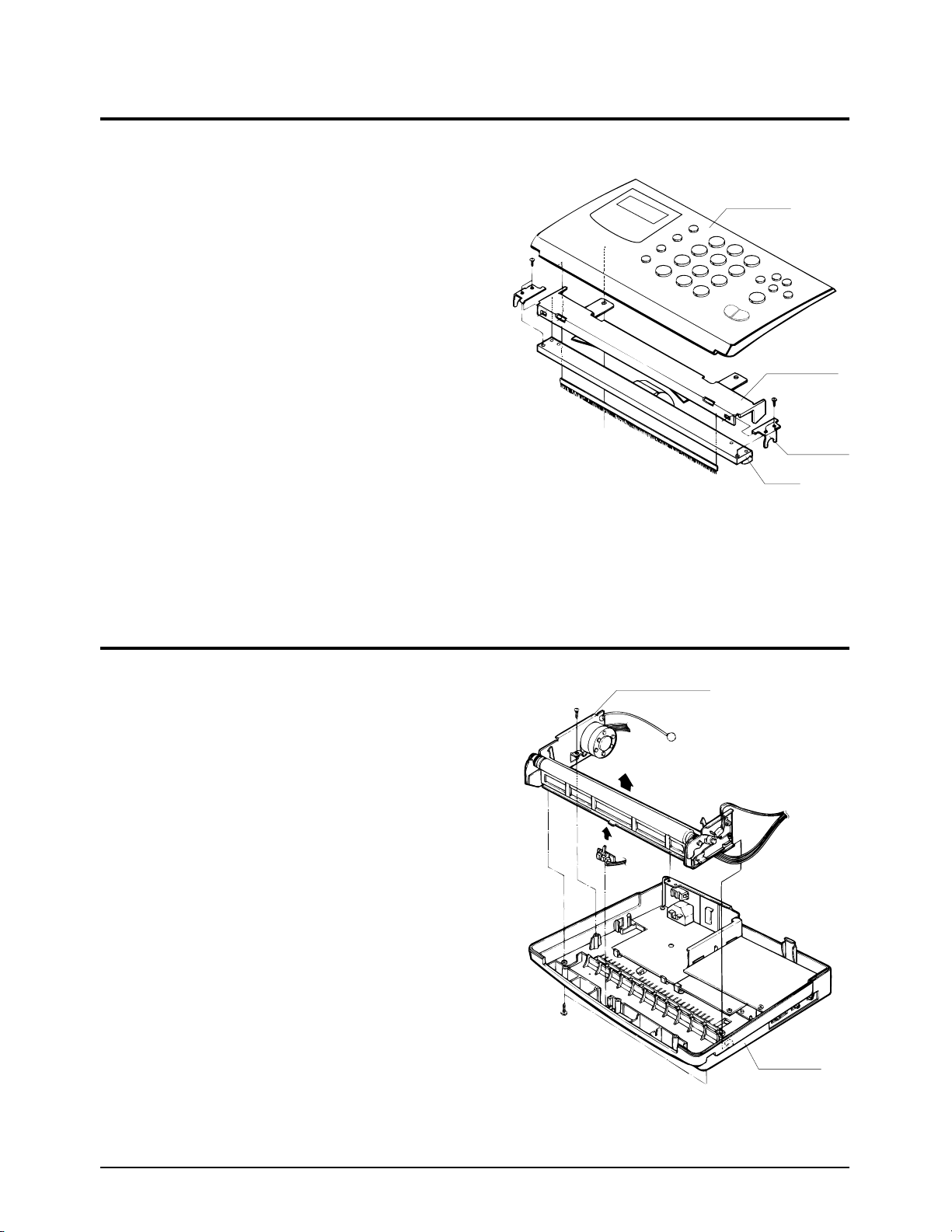
4-2 Top Cover
¥ Loosen the 5 screws fastening the top cover.
¥ Carefully lift the top cover.
¥ Remove the wire harness from the base, as
shown in the figure.
2
1
1
3
3
3
3
3

Disassembly Instruction
4-2 SF150T
4-3. OPE Unit
4-4.
OPE Cover
¥ Loosen the 2 screws fastening the top cover.
¥ Carefully lift the OPE assembly, as shown by
the arrow.
¥ Loosen the 2 screws fastening the OPE chassis.
¥ Remove the Paper Empty sensor connector
from the OPE board.
¥ Remove the OPE unit from the OPE chassis, as
shown by the arrows.
Top Cover
OPE Unit
OPE Cover
OPE Chassis
Figure 4-3
Figure 4-4
Disassembly Instruction
SF150T 4-3
4-5. TPH
¥ Remove the TPH assembly from the OPE unit.
¥ Remove the TPH from the TPH assembly.
¥ Remove the TPH harness from the TPH
connector.
¥ Remove the TPH guide from the TPH.
¥ Lift the white roller assembly.
¥ Loosen the 2 E-rings fastening the main chassis
assembly.
¥ Remove the spring-lock.
¥ Loosen the 2 screws fastening the main chassis
assembly.
¥ Lift the CIS assembly.
¥ Remove the document guide from the CIS
assembly (2 screws).
¥ Remove the CIS guide from the CIS (2 screws).
OPE Cover
TPH Bracket
TPH Guide
TPH
Base Ass'y
Main chassis Ass'y
4-6. Main Frame
Figure 4-5
Figure 4-6

Disassembly Instruction
4-4 SF150T
4-8. BOARDS & POWER SUPPLY
LIU PBA
MAIN PBA
BASE
POWER
¥ Remove the handset modular harness from the
LIU board.
¥ Loosen the screw fastening the LIU board and
carefully lift the LIU board as shown by the
arrow.
¥ Loosen the 3 screws connecting the main and
daughter boards. Lift the rear bracket.
¥ Loosen the screw fastening the daughter board
to the base. Lift the daughter board.
¥ Loosen the 2 screws fastening the power supply
to the base. Lift the power supply and the main
board to remove them.
¥ Lift the modular jack and the earth spring.
¥ Lift the white roller assembly.
¥ Loosen the 2 E-rings fastening the main chassis
assembly.
¥ Remove the spring-lock.
¥ Loosen the 3 screws fastening the main chassis
assembly.
¥ Lift the CIS assembly.
¥ Remove the document guide from the CIS
assembly (2 screws).
¥ Remove the CIS guide from the CIS (2 screws).
4-7. CIS
Figure 4-7
Figure 4-7

SF150T 5-1
5. Circuit Description
5-1 General
The main circuit board controls the machine, and consists of Super Fax Chip (KS16118), External memory,
CODEC circuit with modem-TX and RX signal path and some parts of the Line Interface Unit, Digital TAD
circuit with DSP amd DRAM, witch controls the system.
5-2 System Control Section
This circuit consists of the EP-ROM and SRAM, external Real Time Clock crystal, RTC and memory back-up
circuitry, and the Super Fax Chip (KS16118).
The KS16118 Super Fax Chip is an integrated 9600 bps modem, image processor, 8-bit MPU, peripheral
controller, and analog front end circuit on a single-chip.
Peripheral functions inculde 2-channel SI0, 3-channel DMA, 6-bit Half flash A/D converter, scanner and
video processor units, TPH interface, CODEC unit, and tone generator.
Modem is a 9600 bps, half duplex monolithic device incorporating digital filters, a Samsung SSP1600 digital
signal processor and CPU-Interface logic.
Figure 5-1: KS16118 External Memory Map
1FFFH
0100H
00FFH
0000H
0000H
FFFFH
FF80H
FF7FH
FF00H
FEFFH
/DMS
(SRAM)
Peripheral
PCS0
DSP /CS
PCS1
Interrupt
Vectors
/PMS
(EP-ROM)
[ Program Memory ]
[ Data Memory ]
5-2-1 Memory Map
The external memory of the CPU is devided into, 1 byte(FF00H) DSP chip select, 32kbyte SRAM (0000H
through 7FFFH) and 128kbyte EP-ROM (0100H through 1FFFH).
Circuit Description
5-2 SF150T
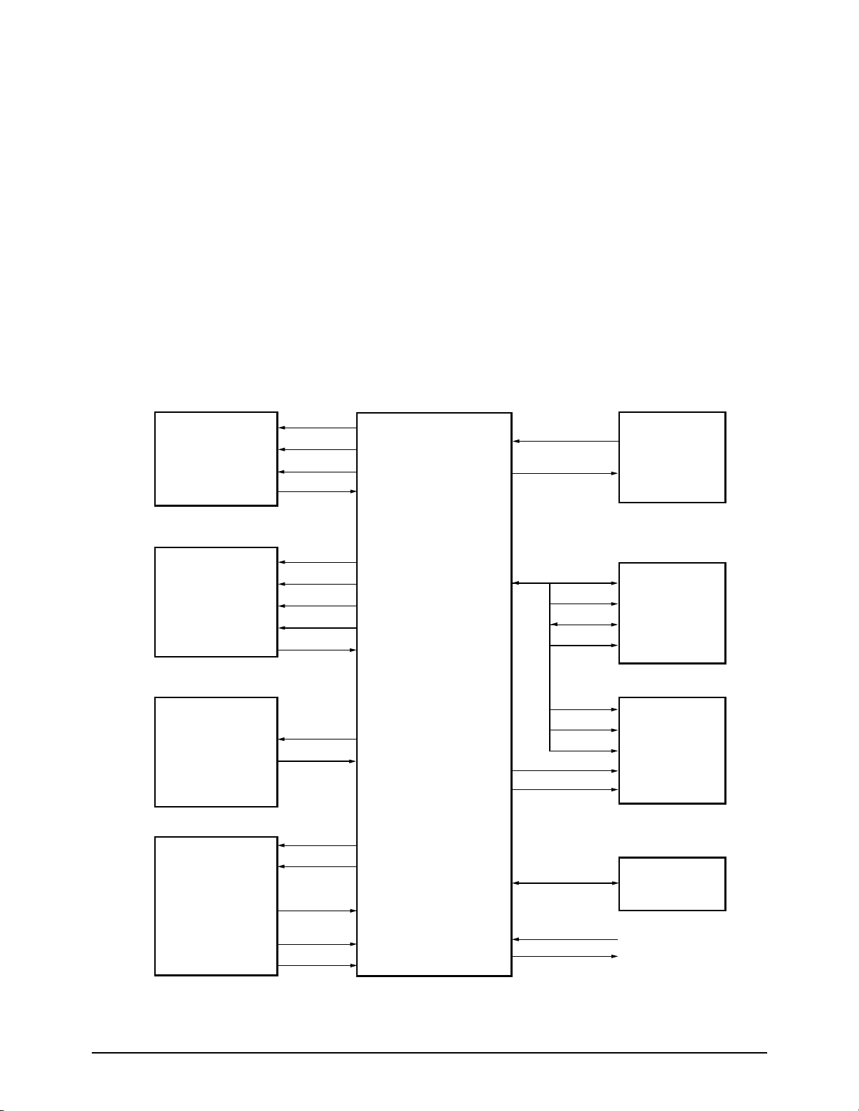
Figure 5-2: XFC Hardware Interface Signals
5-2-2 lExternal Chip Control
KS16118 internal logic generates chip select signals for both memory chips and peripherals.
To support external access, from one to three wait cycles can be inserted under program control during
external access.
A chip select signal line goes active (low) whenever its corresponding device is accessed over the external
interface. The peripheral addresses are located in data memory space.
/DMS : SRAM chip select active (low)
/PMS : EP-ROM chip select active (low)
/PCSn : Peripheral chip select active (low)
D0 - D7 : 8 bit data bus
A0 - A15 : address bus
5-2-3 System Clock
The 12 MHz internal system clock frequency is generated by dividing the 24 MHz clock.
OPERATING
PANEL
PRINTER DATA
CONTROL AND
SENSORS
MOTOR
DRIVER
(MOTOR)
SCANNER
CONTROL
AND
PROCESSING
RTC
CRYSTAL
DATA
MEMORY
PROGRAM
MEMORY
GENERAL
PURPOSE I/ 0
OP00-OP06
LED_CTL
LCD_EN
OPI0-OPI3
STB 0-3
PDAT
PCLK
PLAT
THADI
SM0-SM3
MODE
SI
CLK1
Vin
+Vref
-Vref
XIN
XOUT
/DMS
/RD /WR
D0~D7
A0~A14
/RD
D0~D7
A0~A15
A16
/PMS
RESTOUT
/RESET
KS16118

Circuit Description
SF150T 5-3
Figure 5-4: Printer Timing
5-2-4 Real Time Clock (RTC)
This circuit receives clock pulses from an external
32.768 kHz crystal, which it divides into hours,
minutes, seconds, year, month, and day.
A battery maintains operation when power is off.
KS16118 can up-track 100 years, begining with
1992.
5-2-5 Print Control
The PCLK and PDATA signals synchronize serial
print data to the TPH.
PLAT latches TPH serial print data to the TPH
from a shift register through PDATA.
STB0 - STB3 enable TPH printing in four steps.
This system has a 10ms/line printing format and
sets STB High/Low enable status
according to the STBPOL signal.
PDATA
PCLK
PLAT
STB0
STB1
STB2
STBWID
[0:11]
STB0FF
[0:11]
STB3
Figure 5-6: THD Connection Circuit
GND5
THD1
+5V
R5
R4
Rth
(T)
TPH
Thermistor
5-2-6. A/D Converter (Scanner & TPH
Temperature)
Using a half-flash conversion technique, the 6-bit
A/D converter supports a 0.8µs peak conversion
time and dissipates only 7mA, maximum.
The half-flash unit uses 16 comparators, a most
significant 3-bit ADC, and a least significant 3-bit
ADC.
If the analog input voltage is greater than +Vref,
the A/D conversion result is 3FH.
If the analog input voltage is less than -Vref, the
A/D conversion result is 00H.
A/D conversion register, ADCON (19H), is used
to select an internal or external source for the A/D
converter, to enable or disable the converter, and
to select the operating mode (H: ADin 1 (Scanner),
L: ADin 0 (TPH)).

Circuit Description
5-4 SF150T
5-2-7 Operation Panel Control
Communication
The Operation Panel is controlled by the Port 1,
Port2, and Port 5 registers.
Port 1 (E2H) is a 4-bit general output port for LCD
display data.
This port can be configured for normal data (P1.4P1.7) or alternately as internal MODEM V.24
interface output signals (P1.0-P1.3).
Port 2 (E4H) is an 8-bit port with both input and
I/O pins.
P2.0-P2.3 are input ports for OPE key scan data,
and P2.6-P2.7 are not used for SF150T.
Port 5 (EAH) is an 8-bit port with both output and
I/O pins.
P5.0 and P5.4 are used for LED control and LCD
enable.
5-2-8 Image Sensor
The shading wave is formed by scanning the white
roller prior to a document.
The slice level is determined by the shading wave,
and compensates for shading distortion according
to the CIS characteristics.
The wave format from the CIS is converted into a 6
bit digital value in the KS16118 image processor,
and processed in B/W or intermediate mode.
5-2-9 CIS Input Processor
To process the B/W input signal, maximum (+Vref)
and minimum (-Vref) values of the CIS input signal
are adjusted by calibrating KS16118 in the high state
for maximum level, and setting them to earth for
minimum level.
Shading correction uses a multiplier composed of a
9-bit sequential adder for simple H/W Logic.
5-2-10 CIS Driver
The CIS driver clock (CLK1) frequency is 250 kHz.
A 75% low duty cycle lengthens the charging time.
A start signal (SI) is provided every 10 ms to
match the line scanning time.
Actual image signal (VIN) is provided in less than
6.8 ms, based on A4 paper size using the 250 kHz
clock.
Figure 5-10: CIS Driver Clock Timing
250 KHZ (L:DUTY 75%)
SI
CLOCK
SIG
1 LINE

Circuit Description
SF150T 5-5
5-2-11 I/O Port Table
High Bank Memory
DSP Inactive
DATA = 1
DATA = 1
Active
Active
Active
Active
-
Active
Active
DSP Reset
DSP High Byte
Normal
Normal
CIS LED On
High
OPE LED On
Normal
Normal
-
Open
No Paper
No Document
Normal
Normal
CODEC Serial Clock
CODEC Serial Data
CODEC Enable
-
Closed
Paper Exist
Document Exist
Incomming Ring
Active DSP Data Transfer
Low Bank Memory
DSP Active
DATA = 0
DATA = 0
Inactive
Inactive
Inactive
Inactive
-
Inactive
Inactive
Normal
DSP Low Byte
Low Battery
DSP Response Mode
Off
Low
OPE LED Off
No Barttery
Circuit Symbol
I/O
Pin No.
Port Name
High Low
A16
/DSP_CS
IRXD
ITXD
MOTOR A
MOTOR /A
MOTOR B
MOTOR /B
/CML2
/CML1
/24VCTL
DSPRST
DSPHL
/LOWBAT
DSPACK
/GLED
-
LEDCTL
/NOBAT
SCLK
SDATS
/SDEN
/HOOK DET2
MODE
P_EMPTY
D_DET
RING_DET
/DSPFLAG
P0.0
P0.1
P2.4
P2.5
P3.0
P3.1
P3.2
P3.3
P3.4
P3.5
P3.6
P4.1
P4.2
P4.4
P4.5
P4.6
P4.7
P5.0
P5.3
P5.5
P5.6
P5.7
P6.1
P6.2
P6.3
P6.4
P6.5
P6.6
O
PCS
I
O
O
O
O
O
O
O
O
O
O
I
O
O
O
O
I
O
O
I
I
I
I
I
I
I
34
35
45
46
49
50
51
52
53
54
55
93
92
90
89
87
88
126
96
137
138
139
59
60
61
62
63
116
 Loading...