

SAMSUNG SF150TB Service Manual

FACSIMILE
SF150T
CONTENTS
1. Precautions
2. Specification
3. Operating Instructions
4. Disassembly and Reassembly
5. Circuit Description
6. Troubleshooting
7. Electrical Parts List
8. Exploded Views and Parts List
9. PCB Diagrams
10. Block Diagram
11. Wiring Diagram
12. Schematic Diagrams
FACSIMILE
SERVICE
Manual
0
0
0
0
0
0
0
0
0
0
0
0
0
0
0
0
0
0
0
0
0
0

SF150T 1-1
1. Be sure that all built-in protective devices are
in place. Restore any missing protective
shields.
2. Make sure there are no cabinet openings
through which people- particularly childrenmight insert fingers or objects and contact
moving parts or dangerous voltages.
3. When re-installing chassis and assemblies, be
sure to restore all protective devices, including
control knobs and compartment covers.
4. Design Alteration Warning:
Never alter or add to the mechanical or
electrical design of this equipment, such as
auxiliary connectors, etc. Such alterations and
modifications will void the manufacturer's
warranty.
5 Components, parts, and wiring that appear to
have overheated or are otherwise damaged
should be replaced with parts which meet the
original specifications. Always determine the
cause of damage or overheating, and correct
any potential hazards.
6. Observe the original lead dress, especially near
sharp edges, AC, and high voltage power
supplies. Always inspect for pinched, out-ofplace, or frayed wiring. Do not change the
spacing between components and the printed
circuit board.
7. Product Safety Notice:
Some electrical and mechanical parts have
special safety-related characteristics which
might not be obvious from visual inspection.
These safety features and the protection they
provide could be lost if a replacement
component differs from the original. This
holds true, even though the replacement may
be rated for higher voltage, wattage, etc.
8. Components critical for safety are indicated in
the parts list with symbols . Use only
replacement components that have the same
ratings, especially for flame resistance and
dielectric specifications. A replacement part
that does not have the same safety
characteristics as the original may create
shock, fire, or other safety hazards.
1 Precautions
Follow these safety, ESD, and servicing precautions to prevent personal injury and equipment damage.
1-1 Safety Precautions

1. Immediately before handling a semiconductor
component or semiconductor-equipped
assembly, drain off any electrostatic charge on
your body by touching a known earth ground.
Alternatively, employ a commercially
available wrist strap device, which should be
removed for your personal safety reasons prior to
applying power to the unit under test.
2. After removing an electrical assembly
equipped with ESDs, place the assembly on a
conductive surface, such as aluminum or
copper foil, or conductive foam, to prevent
electrostatic charge buildup in the vicinity of
the assembly.
3. Use only a grounded-tip soldering iron to
solder or desolder ESDs.
4. Use only an "anti-static" solder removal device.
Some solder removal devices not classified as
"anti-static" can generate electrical charges
sufficient to damage ESDs.
5. Do not use Freon-propelled chemicals. When
sprayed, these can generate electrical charges
sufficient to damage ESDs.
6. Do not remove a replacement ESD from its
protective packaging until immediately before
installing it. Most replacement ESDs are
packaged with all leads shorted together by
conductive foam, aluminum foil, or a
comparable conductive material.
7. Immediately before removing the protective
shorting material from the leads of a
replacement ESD, touch the protective material
to the chassis or circuit assembly into which
the device will be installed.
8. Maintain continuous electrical contact between
the ESD and the assembly into which it will be
installed, until completely plugged or soldered
into the circuit.
9. Minimize bodily motions when handling
unpackaged replacement ESDs. Normal
motions, such as the brushing together of
clothing fabric and lifting one's foot from a
carpeted floor, can generate static electricity
sufficient to damage an ESD.
Precautions
1-2 SF150T
1. Exercise caution when replacing a Lithium
battery. There could be a danger of explosion
and subsequent operator injury and/or
equipment damage if incorrectly installed.
2. Be sure to replace the battery with the same or
equivalent type recommended by the
manufacturer.
3. Lithium batteries contain toxic substances and
should not be opened, crushed, or burned for
disposal.
1-3 Lithium Battery Precautions
1-2 ESD Precautions
Certain semiconductor devices can be easily damaged by static electricity. Such components are commonly
called "Electrostatically Sensitive (ES) Devices", or ESDs. Examples of typical ESDs are: integrated circuits,
some field effect transistors, and semiconductor "chip" components.
The techniques outlined below should be followed to help reduce the incidence of component damage
caused by static electricity.
CAUTION: Be sure no power is applied to the chassis or circuit, and observe all other safety precautions.
8-1SF150T
1
2
S4
4
8
10
11
S2
S2
S3
5
S1
S1
6
7
12
9
3
8. Exploded Views and Parts Lists
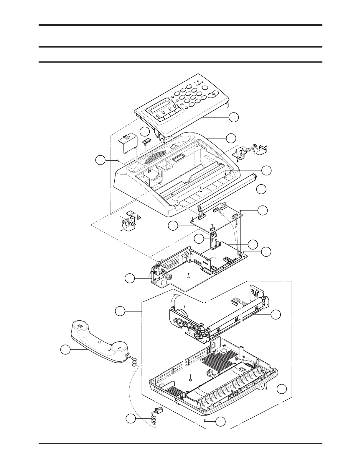
8-1. Total Assembly

8-2 SF150T
Exploded Views and Parts Lists
Total Assembly Parts Lists
Location No. Description SEC. Code Q'ty Remark
1 ASS'Y-OPE UNIT JF96-01296A 1
2 ASS’Y-TOP COVER JF96-01297A 1
3 SPACER JF72-40611A 1
4 GUIDE-TX JF72-41122Z 1
5 PBA-LIU JF92-00843Q 1
6 REAR-BRKT JF70-10681A 1
7 PBA-MAIN JF92-00842E 1
8 SMPS-V2, AC/DC JF44-10059A 1
9 ASS’Y-BASE UNIT JF96-01298A 1
10 ASS’Y-MAIN CHASSIS UNIT JF96-01253A 1
11 ASS’Y-HANDSET JF96-01262A 1
12 CURL-CORD JF39-60075A 1
S1 SCREW, TAPTITE, BH, +, M3, L8 6003-000015 11
S2 SCREW, TAPTITE, BH, +, M3, L6 6003-000261 2
S3 SCREW, TAPTITE, BH, +, M3, L6 6003-000115 2

Exploded Views and Parts Lists
8-2. Ass'y OPE Unit
SF150T 8-3
2
1
3
4
5
6
7
10
11
9
13
14
15
16
17
18
19
20
21
22
23
24
25
S1
S2
S3
26
8
12
27

Ass'y OPE Unit Parts Lists
Exploded Views and Parts Lists
8-4 SF150T
Location No. Description SEC. Code Q'ty Remark
ASS'Y-OPE UNIT JF96-01296A 1
1 OPE COVER JF72-42016Z 1
2 LCD-WINDOW JF75-11004F 1
3 KEY-ONETOUCH JF72-42021A 1
4 KEY-OHD JF72-42022A 1
5 KEY-STOP JF72-42029A 1
6 KEY-START JF72-42028A 1
7 KEY-TEL JF72-42026A 1
8 KEY-TAD(A) JF72-42056A 1
9 KEY-TAD(B) JF72-42057A 1
10 KEY-MENU JF72-42020A 1
11 KEY-RESOLUTION JF72-42018B 1
12 KEY-RECEIVE JF72-42017B 1
13 KEY-ANSWER JF72-42019M 1
14 RUBBER-CONTACT JF73-40521A 1
15 DISPLAY-LCD JF07-20061A 1
16 CBF-WIRE, MAIN-OPE, 18 P JF39-41081A 1
17 CBF-WIRE, LIU-OPE, 7 P JF39-40957A 1
18 PBA-OPE JF92-00844B 1
19 CHASSIS OPE UNIT JF70-10863A 1
20 BRKT-TPH UNIT JF70-10861B 1
21 GUIDE-TPH(R) JF70-10679A 1
22 PRINT HEAD-THERMAL JF47-30069B 1
23 PBA-P.EMPTY JF92-00704B 1
24 GUIDE-TPH(L) JF70-10679B 1
25 CBF-WIRE, MAIN-TPH, 14P JF39-40955A 1
26 BRUSH-ANTISTATIC JF75-10650A 1
27 FLAT CABLE, OPE-LCD JF39-41018A 1
S1 SCREW, TAPTITE, PWH, +, B, M2. 6003-000193 11
S2 SCREW-MACHINE, BH, +, M3, L4 6001-000125 4
S3 SCREW, TAPTITE, BH, +, B, M3, L 6003-000015 2
Exploded Views and Parts Lists
SF150T 8-5
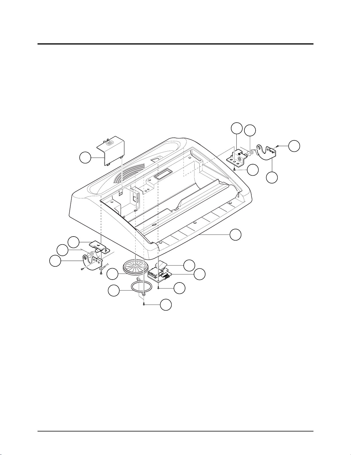
8-3. Ass'y COVER TOP
1
2
3
4
6
7
8
S1
9
10
S2
S3
S3
11
12
5

Exploded Views and Parts Lists
8-6 SF150T
Location No. Description SEC. Code Q'ty Remark
ASSEMBLY-COVER TOP JF96-01297A 1
1 TOP COVER JF72-42015A 1
2 HINGE-OPE(R) JF70-10676A 1
3 COVER-SPRING(R) JF70-40562A 1
4 HINGE-BRKT(R) JF70-10677A 1
5 BATTERY-COVER JF72-42027A 1
6 HINGE-BRKT(L) JF70-10677B 1
7 COVER-SPRING(L) JF70-40562B 1
8 HINGE-OPE(L) JF70-10676B 1
9 SWITCH-HOOK, 48 V, 200 mA 3409-000117 1
10 PBA-HOOK JF92-00845C 1
11 SPEAKER, 1 W, 8 OHM, 83dB 3001-001044 1
12 UNIT-FIXING BRKT GB70-10500A 1
S1 SCREW, TAPTITE, BH, +, M3, L6 6003-000261 3
S2 SCREW, TAPTITE, BH, +, M3, L8 6003-000015 2
S3 SCREW, TAPTITE, PWH, +, B, M2.5, L6 6003-000193 2
Ass'y COVER TOP Parts Lists
Exploded Views and Parts Lists
SF150T 8-7
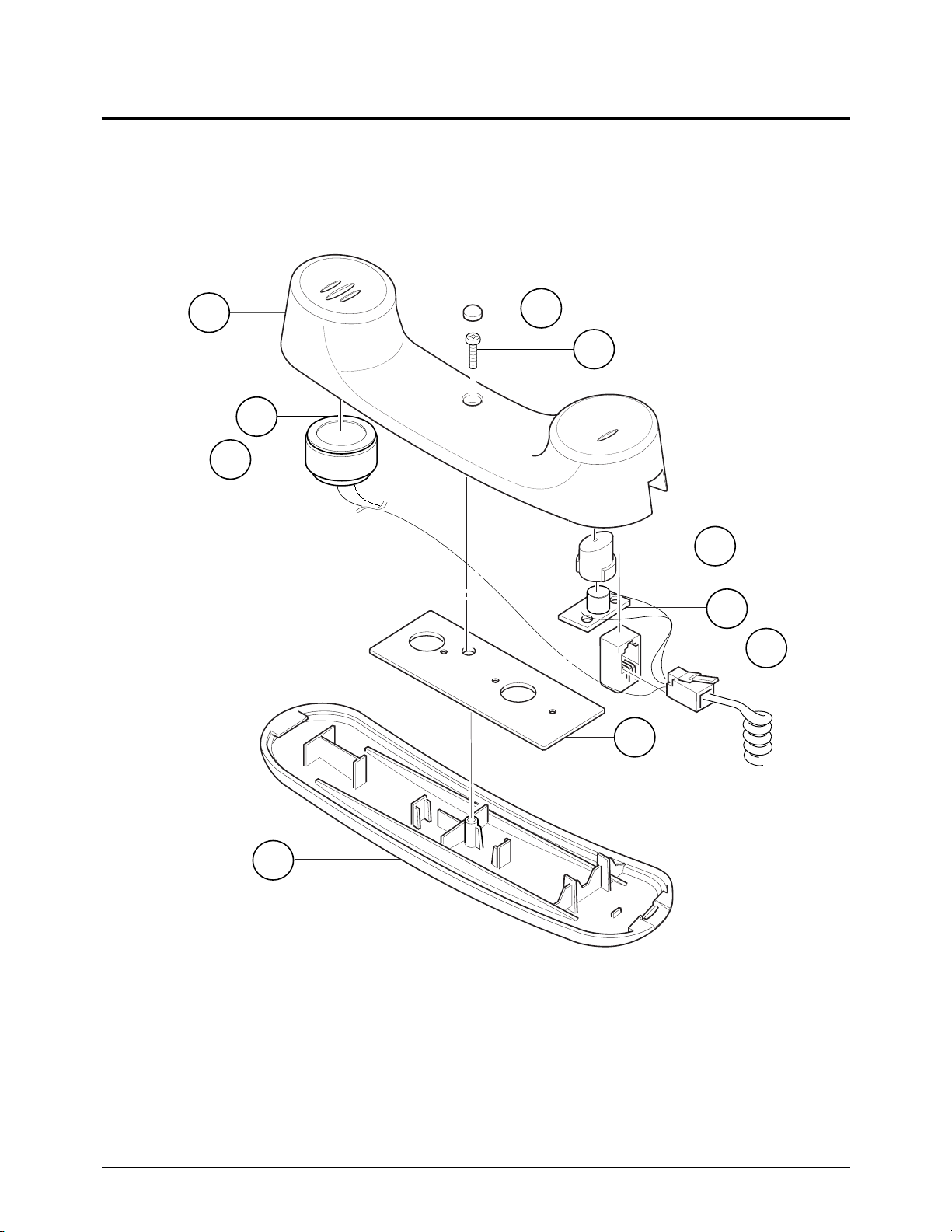
8-4. Ass’y Handset
3
2
S1
1
4
5
6
7
8
9

Exploded Views and Parts Lists
8-8 SF150T
Ass’y Handset Parts Lists
Location No. Description SEC. Code Q'ty Remark
ASS'Y-HANDSET JF96-01262A 1
1 HANDSET-LOWER JF72-42014A 1
2 AUDIO-RECEIVER, 160 OHM 3009-001001 1
3 HOLD-DUMMY GB72-40792A 1
4 RUBBER-MIC JF73-40501A 1
5 PBA-H/S MIC JF92-00625A 1
6 CBF-HARNESS JF39-40834A 1
7 WEIGHT-BALANCE JF70-10864A 1
8 HANDSET-UPPER JF72-42013A 1
9 RING-OP, ID17, OD35 6044-000138 1
S1 SCREW, TAPTITE, PH, +, B, M3, 6003-000168 1

Exploded Views and Parts Lists
SF150T 8-9
8-5. Ass'y Base
5
6
7
8
S1
2
1
3
4
10
9

Exploded Views and Parts Lists
8-10 SF150T
Ass'y Base Parts Lists
Location No. Description SEC. Code Q'ty Remark
ASS'Y-BASE JF96-01298A 1
1 CBF-WIRE, MAIN-CIS/MODE JF39-41062A 1
2 MICRO-SWITCH 3405-000166 1
3 STEP-MOTER, 7.5 DEG, 24 V 3101-000171 1
4 ASS’Y-MAIN CHASSIS UNIT JF96-01253A 1
5 BASE JF72-42025A 1
6 PBA-D’DET JF92-00888A 1
7 CBF-WIRE, HANDSET-LIU JF39-41066A 1
8 RUBBER-FOOT JF73-10002A 2
9 MIC-CONDENSOR 3003-000120 1
10 MIC-ADAPTER GB72-40770A 1
S1 SCREW, TAPTITE, BH, +, M3, L6 6003-000261 2
Exploded Views and Parts Lists
SF150T 8-11
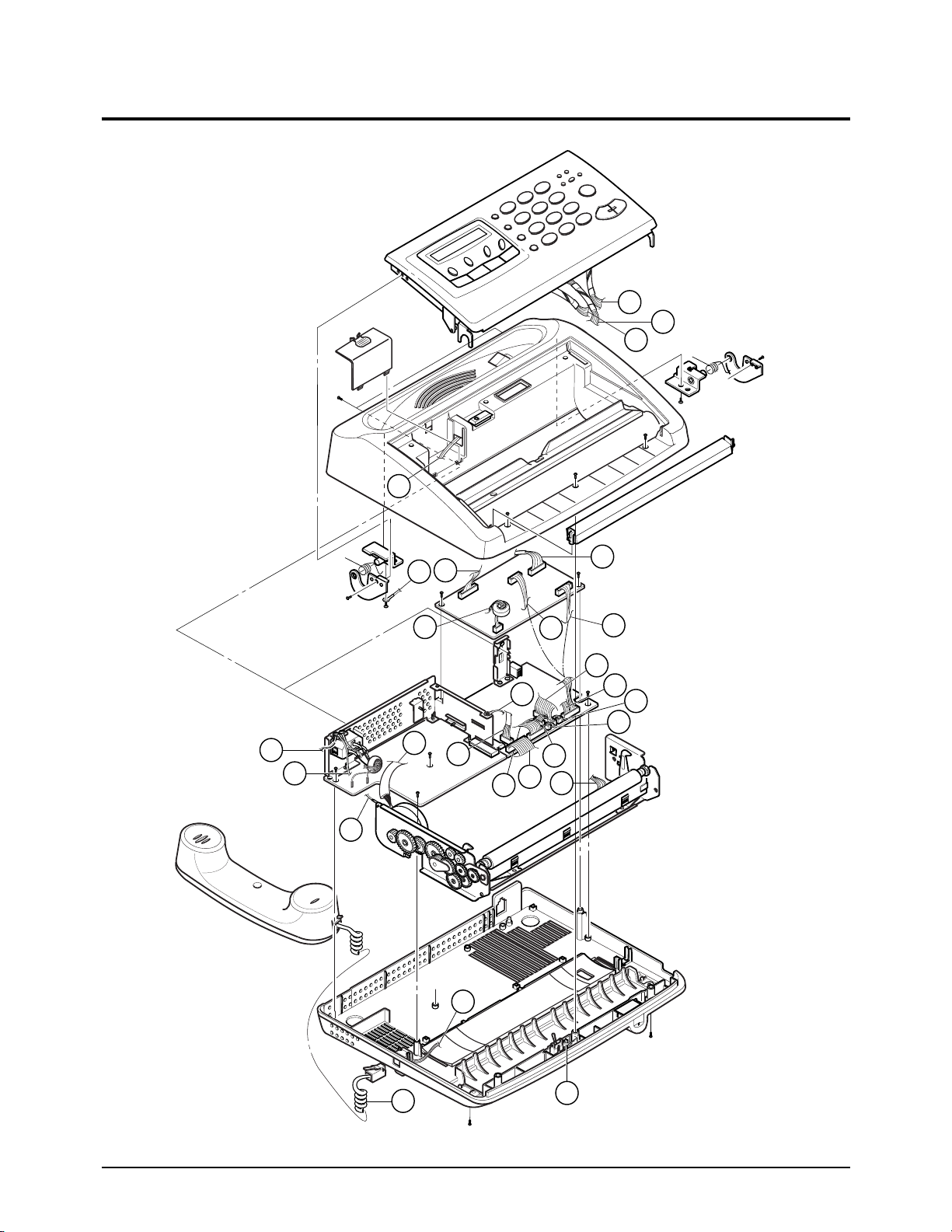
8-6. Harness
1
2
3
11
3'
5
9
4
4'
6
8'
8
1'
2'
15
6'
4''
10'
11'
10
12
5'
7'
13
14
7
14'

Exploded Views and Parts Lists
8-12 SF150T
Harness Parts Lists
Location No. Description SEC. Code Q'ty Remark
1 CBF-WIRE, MAIN-TPH, 14 P JF39-40955A
2 CBF-WIRE, MAIN-OPE, 18 P JF39-41081A
3 CBF-WIRE, LIU-OPE, 7 P JF39-40957A
4 CBF-WIRE, MAIN-LIU, 22 P JF39-41063A
5 CBF-WIRE, LIU-HANDSET JF39-41066A
6 CBF-WIRE, MAIN-CIS/MODE JF39-41062A
7 CBF-WIRE, MAIN-D.DET, MIC, 5 P JF39-41078A
8 STEP-MOTER, 7.5 DEG, 24 V 3101-000171
9 CBF-WIRE, LIU-HOOK JF39-41080A
10 CBF-WIRE, POWER-MOTOR JF39-40963B
11 CBF-WIRE, POWER-TOP COVER JF39-40962B
12 CURL CORD JF39-60075A
13 CABLE CLAMP 6502-001026
14 CBF-WIRE, MAIN-BATTERY, 2 P JF39-41082A
15 CBF-WIRE, MAIN-SPEAKER, 2 P JF39-41079A

Y
Y
Y
Y
Y
YY
Y
N
N
NN
YY Y
NN N N
N
N
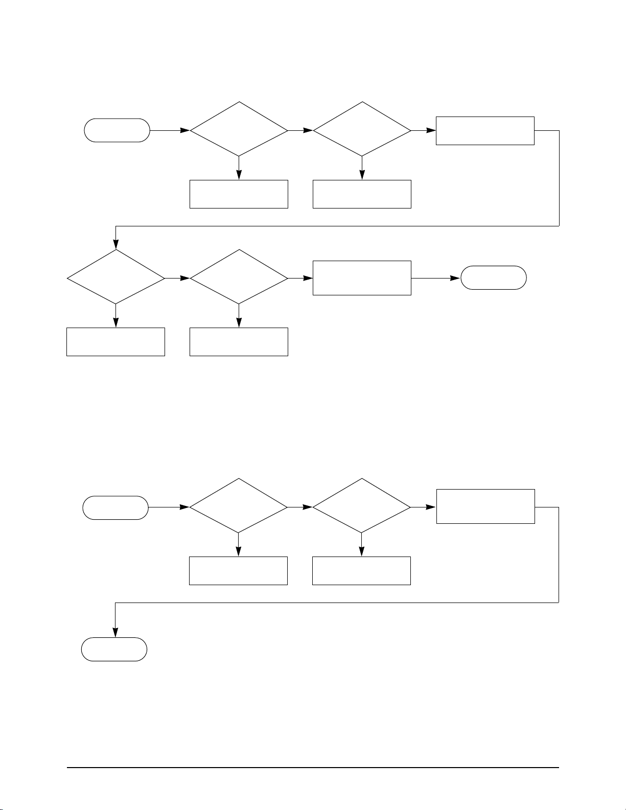
6. Troubleshooting
6-1. Initial Checkout and Overall Troubleshooting Flow
SF150T 6-1
Plug in the power
cord
Load document in
feeder
Copy OK ?
OGM play back ?
Call machine from
another phone
Auto Answer
OK ?
ICM Recording ?
Manual
operation OK ?
OGM Recording
RX OK ?
Document feed ? Push 'START' Key CIS ON ?
System
initialized ?
See Section 6-3 See Section 6-2
See Section 6-5See Section 6-4
See Section 6-5
See Section 6-8
See Section 6-7
See Section 6-6
See Section 6-9 See Section 6-10
A
Power Supply
OK ?
Start

Troubleshooting
6-2 SF150T
YY
N N
Lift Handset
off hook
Dial tone OK ? TX OK ?
See Section 6-11
End
See Section 6-12
A

Troubleshooting
SF150T 6-3
6-2. Check Power Supply
N
N
Check AC socket
voltage
Power cord
connected ?
Start
220 - 240 VAC?
Y
Y
END
Connect as required Notify customer
N N
N
Check
Power Cord
Continuity
Replace Cord Replace Fuse Replace Q1
YY
Fuse OK ?
Q1 OK ?
Y
N
R5 changed
value ?
Remove short
End

Troubleshooting
6-4 SF150T
6-2-1 No + 5 V
Y
NN
output shorted ?Start
N
Y Y
N
Remove short
Y
Replace D4
Check PCB Pattern Replace U2
Check CON 1
Check
U2 Input voltage
D4 Open or
Shorted ?
DC 6 V Check U2 ?
End
6-2-2 No -12 V
YY
N N
output shorted ?
Start
N
Y Y
N
Remove short Replace D5
Check PCB Pattern Replace U1
Check CON1
Check
U1 Input voltage
D5 Open or
Shorted ?
-15 VDC U1 Output ?
End
Troubleshooting
SF150T 6-5
Y
Y
N
N
output shorted ?
Start
N
Y Y
N
Remove short
Replace D3
OVP operation
Restart Replace Q3
Check CON1
D3 Open or
Shorted ?
Check
OVP operation
Q3 OK ?
End
6-2-3 No + 24 V
6-2-4 + 24 V TPH Doesn't output
YN
Check
C/S port short ?
Start
N
Y
Remove short Replace Q5
Check CON1
Q5 OK ?
End

Troubleshooting
6-6 SF150T
6-3. System Not Initialized
N
NG
N
N
NG
OK
N
N
N
Step motor driving
Start
Y
Y
Y
Y
OK
NG
Y
Y
See Section 6-2-2
Replace P5 Harness
or OPE PBA
Replace U3
Replace U7
Fax Engine IC
Replace U7
Fax Engine IC
Replace Main PBA
Replace U14
Motor Driver
Replace
X2 XTAL
Check
U3 Pin 5
= "High"
Check U3 Pin 6
(above +2.25 V)
Check
P5 Harness or OPE
PBA
Check 12 MHz
Clock U7-37
Check 24 MHz
Clock U7-129
O.K ?
O.K ?
Check
Vcc ³ 4.75 V
P1-4 (+5V)
P1-3 (GND5)
End
End
 Loading...