

Page 1
3. Disassembly and Reassemble
3. Disassembly and Reassembly
This section of the service manual describes the disassembly and reassembly procedures for the LED TV.
This LED TV contains electrostatically sensitive devices. Use caution when handling these components.
WARNING
3-1. Disassembly and Reassembly
Disconnect the LED TV from the power source before disassembly.1.
Follow these directions carefully; never use metal instruments to pry apart the cabinet.2.
CAUTION
3-1-1. LED TV
32 / 40 / 46 Inches
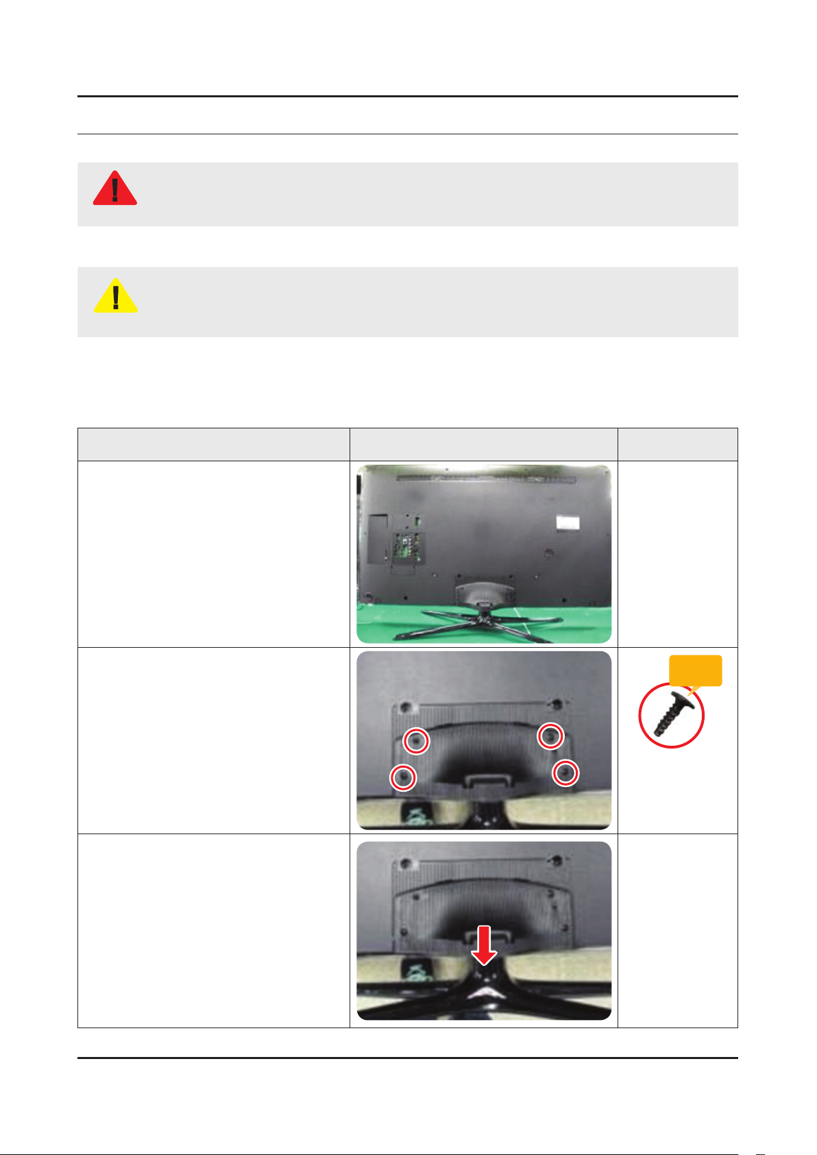
Place TV face down on cushioned table.
If there is no additional coment, it is same for all inches.3.
Description Picture Description Screws
1
Remove 4 screws from the ASSY
2
GUIDE P-STAND.
Remove STAND.
3
Torque :
9~11Kgf.cm.
128~156psi
6003-001782
SCREW-MACHINE
M4.0, L12.0 BLK
3-1
Page 2
3-2
3. Disassembly and Reassemble
Description Picture Description Screws
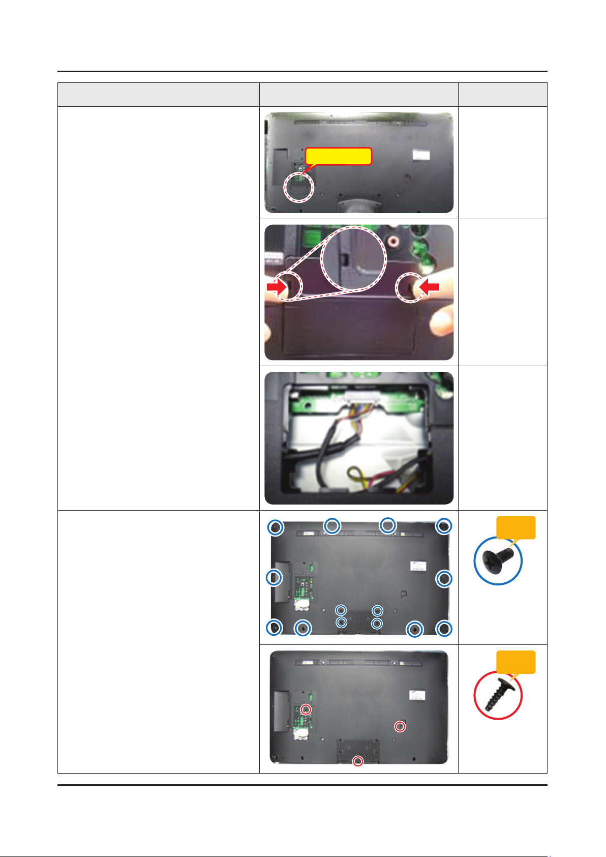
Remove the COVER-JACK after push
4
the locking in both sides.
COVER-JACK
Remove screws of ASSY COVER
5
P-MIDDLE, REAR.
32 inch : 9 EA •
40 inch : 14 EA•
46 inch : 14 EA •
32 inch : 2 EA •
40 inch : 2 EA•
46 inch : 3 EA•
Torque :
7~8Kgf.cm.
100~113psi
6001-002755
SCREW-MACHINE
M3.0, L6.0 BLK
Torque :
9~11Kgf.cm.
128~156psi
6003-001782
SCREW-MACHINE
M4.0, L12.0 BLK
Page 3
3-3
3. Disassembly and Reassemble
Description Picture Description Screws
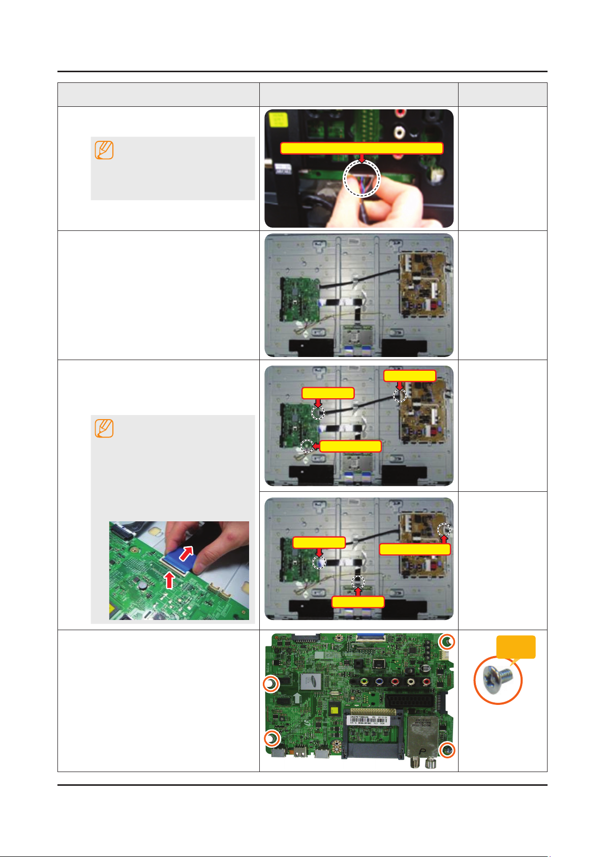
Disconnect the ASSY BOARD P-JOG
6
SWITCH & IR Cable.
NOTE
First remove the cable before you
remove the ASSY COVER P-MIDDLE,
REAR.
Remove the ASSY COVER P-MIDDLE,
7
REAR.
Remove the Power Cables and Speaker
8
Cables.
Remove the LVDS Cable and Panel
Drive Cable.
NOTE
ASSY BOARD P-JOG SWITCH & IR Cable
Power Cable
Power Cable
Applied to Double locking.
Flip up the locking tab on top of the 1.
connector.
Squeeze the edge of the connector 2.
to release the second tab lock and
gently pull the connector away.
Remove the screws of ASSY PCB
9
MAIN.
Speaker Cable
LVDS Cable
LVDS Cable
Panel Drive Cable
Torque :
7~8Kgf.cm.
100~113psi
6001-002756
SCREW-MACHINE
M3.0, L6.0 WHT
Page 4
3-4
3. Disassembly and Reassemble
Description Picture Description Screws
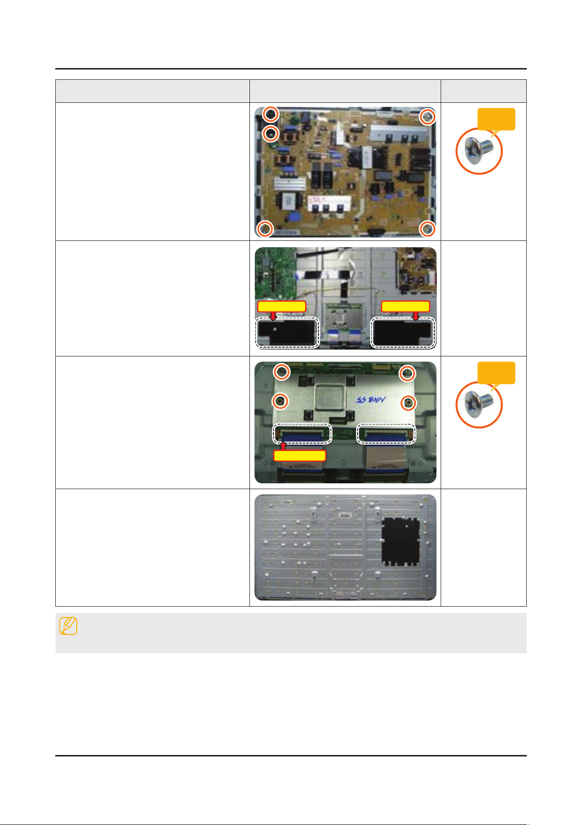
Remove the screws of DC VSS-LED TV
10
PD BD.
Remove the ASSY SPEAKER (L/R).
11
Remove the 4 screws of ASSY T CON
12
and unlock the locking of T CON Cable.
Speakers(L) Speakers(R)
Torque :
7~8Kgf.cm.
100~113psi
6001-002756
SCREW-MACHINE
M3.0, L6.0 WHT
Torque :
7~8Kgf.cm.
100~113psi
T CON Cable
Completed disassembly.
13
Reassembly procedures are in the reverse order of disassembly procedures.
Panel.•
NOTE
6001-002756
SCREW-MACHINE
M3.0, L6.0 WHT
Page 5
3-5
3. Disassembly and Reassemble
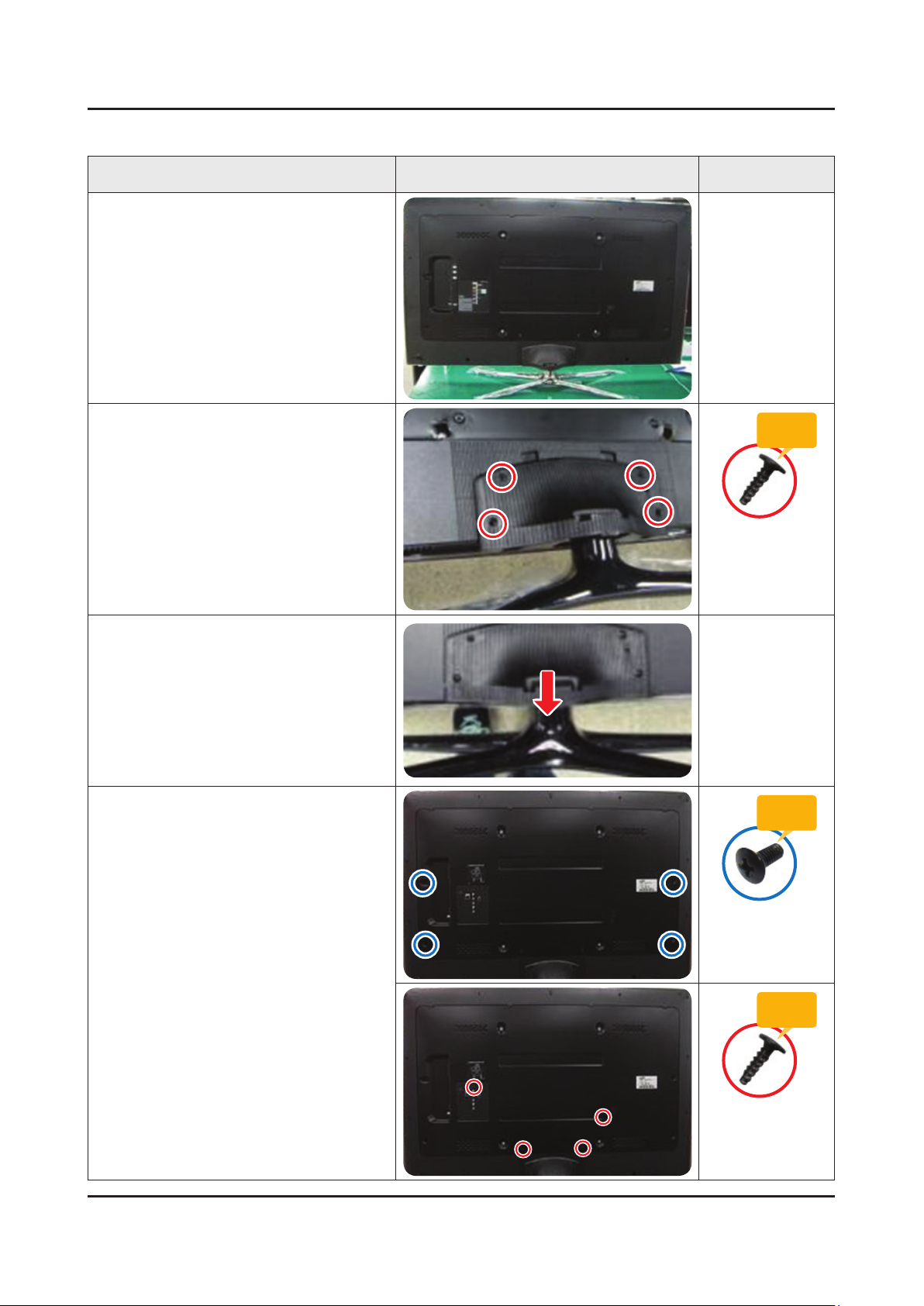
55 Inches
Description Picture Description Screws
Place TV face down on cushioned table.
1
Remove 4 screws from the ASSY
2
GUIDE P-STAND.
Remove STAND.
3
Remove screws of ASSY COVER
4
P-REAR.
55 inch : 4 EA •
Torque :
9~11Kgf.cm.
128~156psi
6003-001782
SCREW-MACHINE
M4.0, L12.0 BLK
Torque :
7~8Kgf.cm.
100~113psi
6001-002755
SCREW-MACHINE
M3.0, L6.0 BLK
55 inch : 4 EA •
SCREW-MACHINE
M4.0, L12.0 BLK
Torque :
9~11Kgf.cm.
128~156psi
6003-001782
Page 6
3-6
3. Disassembly and Reassemble
Description Picture Description Screws
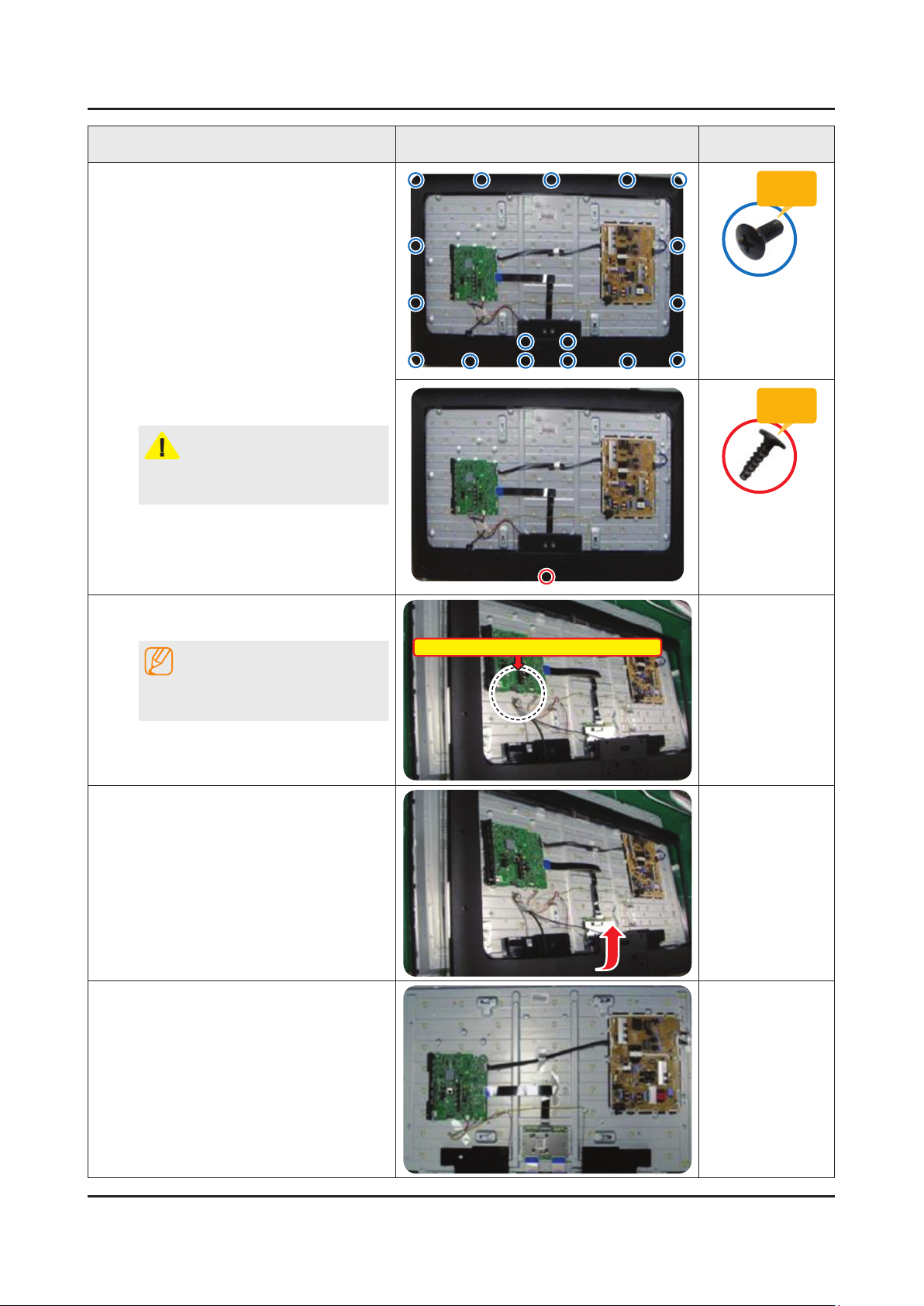
Remove 17 screws of ASSY COVER
5
P-MIDDLE.
Remove 1 screws of ASSY COVER
P-MIDDLE.
CAUTION
Becareful when you lift up the ASSY
COVER P-MIDDLE, It's really sharp.
Disconnect the ASSY BOARD P-JOG
6
SWITCH & IR Cable.
NOTE
ASSY BOARD P-JOG SWITCH & IR Cable
Torque :
7~8Kgf.cm.
100~113psi
6001-002755
SCREW-MACHINE
M3.0, L6.0 BLK
Torque :
9~11Kgf.cm.
128~156psi
6003-001782
SCREW-MACHINE
M4.0, L12.0 BLK
First remove the cable before you
remove the ASSY COVER P-MIDDLE.
Lift up the ASSY COVER P-MIDDLE.
7
Remove the ASSY COVER P-MIDDLE.
8
Page 7
3-7
3. Disassembly and Reassemble
Description Picture Description Screws
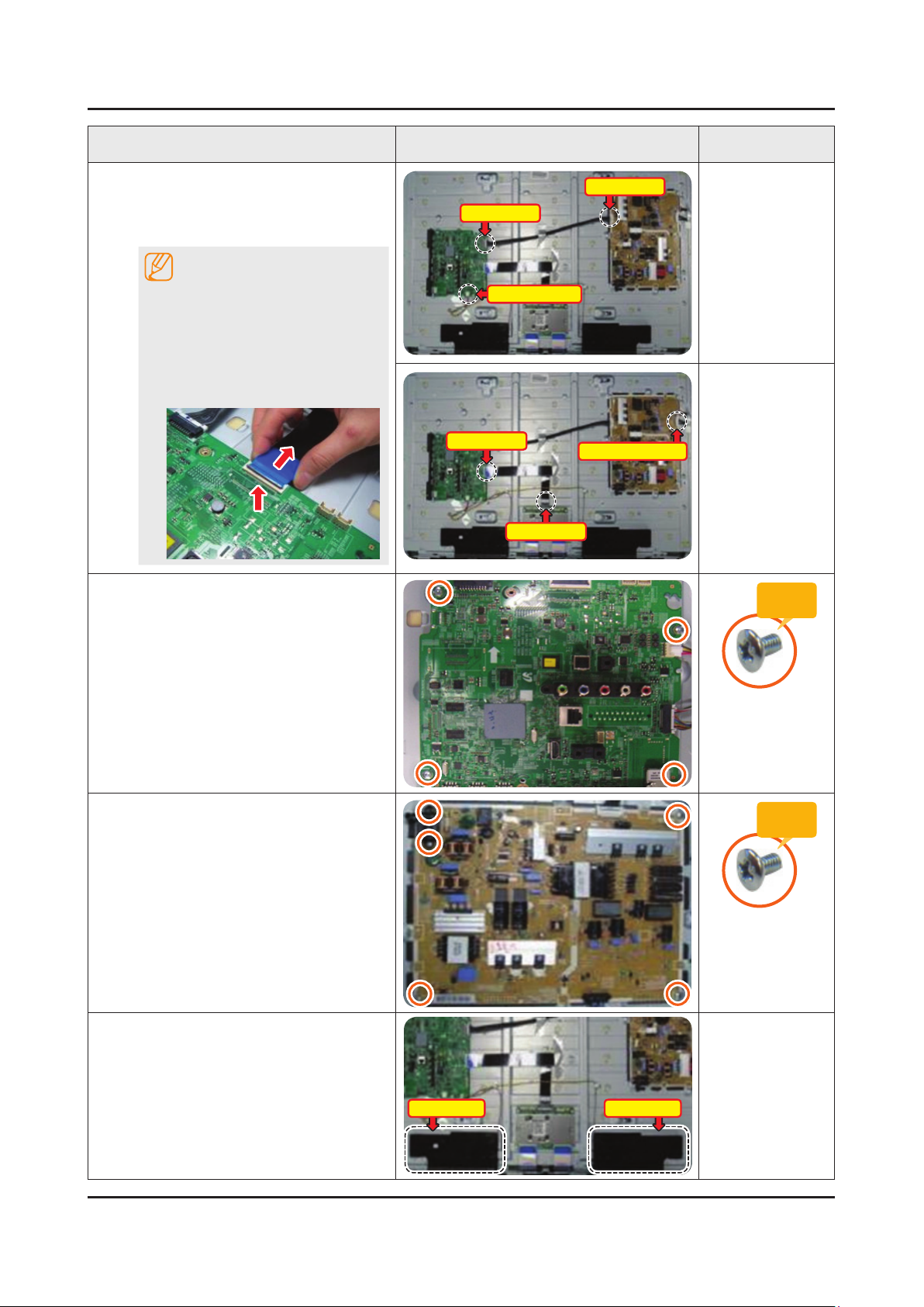
Remove the Power Cables and Speaker
9
Cables.
Remove the LVDS Cable and Panel
Drive Cable.
NOTE
Applied to Double locking.
Flip up the locking tab on top of the 1.
connector.
Squeeze the edge of the connector 2.
to release the second tab lock and
gently pull the connector away.
Remove the screws of ASSY PCB
10
MAIN.
Power Cable
Speaker Cable
LVDS Cable
LVDS Cable
Power Cable
Panel Drive Cable
Torque :
7~8Kgf.cm.
100~113psi
Remove the screws of DC VSS-LED TV
11
PD BD.
Remove the ASSY SPEAKER (L/R).
12
Speakers(L) Speakers(R)
6001-002756
SCREW-MACHINE
M3.0, L6.0 WHT
Torque :
7~8Kgf.cm.
100~113psi
6001-002756
SCREW-MACHINE
M3.0, L6.0 WHT
Page 8
3-8
3. Disassembly and Reassemble
Description Picture Description Screws
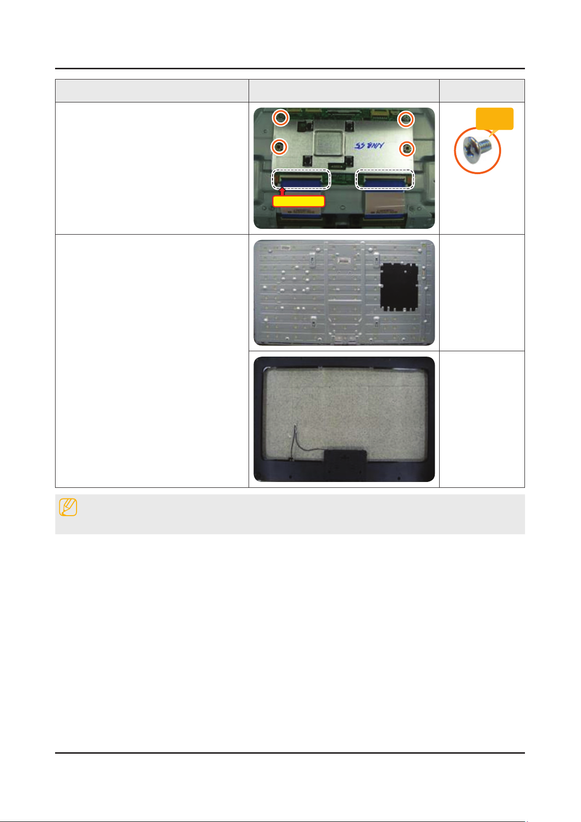
Remove the 4 screws of ASSY T CON
13
and unlock the locking of T CON Cable.
Completed disassembly.
14
Panel.•
ASSY COVER P-MIDDLE.•
T CON Cable
Torque :
7~8Kgf.cm.
100~113psi
6001-002756
SCREW-MACHINE
M3.0, L6.0 WHT
NOTE
Reassembly procedures are in the reverse order of disassembly procedures.
Page 9
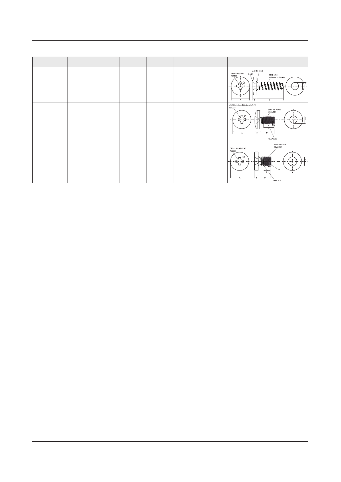
3-9
3. Disassembly and Reassemble
A
CROSS #2(3.56)
RECESS
B 8.0R
★ C 0.6 ± 0.1
M4.0 x 1.8
TAPPING △ B-TYPE
BD
C
A
CROSS #2(3.08 특수 Punch D:7.5
RECESS
M3 x 0.5 PITCH
SCALOCK
TRAP 도포
인치
BD
E
C
A
CROSS #2(★M3.0F)
RECESS
M3 x 0.5 PITCH
SCALOCK
B
B
D
C
TRAP 도포
인치
Screw Size
Code No. COLOR A (mm) B (mm) C (mm) D (mm) E (mm) Screw Image
6003-001782 BLACK 7.80~8.20 1.85~1.95 3.81~3.91 11.4~12.0 -
6001-002755 BLACK 7.1~7.5 1.9~2.0 2.98~3.02 5.7~6.0 4.4~5.4
6001-002756 WHITE 5.6~6.0 1.15~1.25 2.92~2.98 3.7~4.0 4.4~5.4
Page 10
3. Disassembly and Reassemble
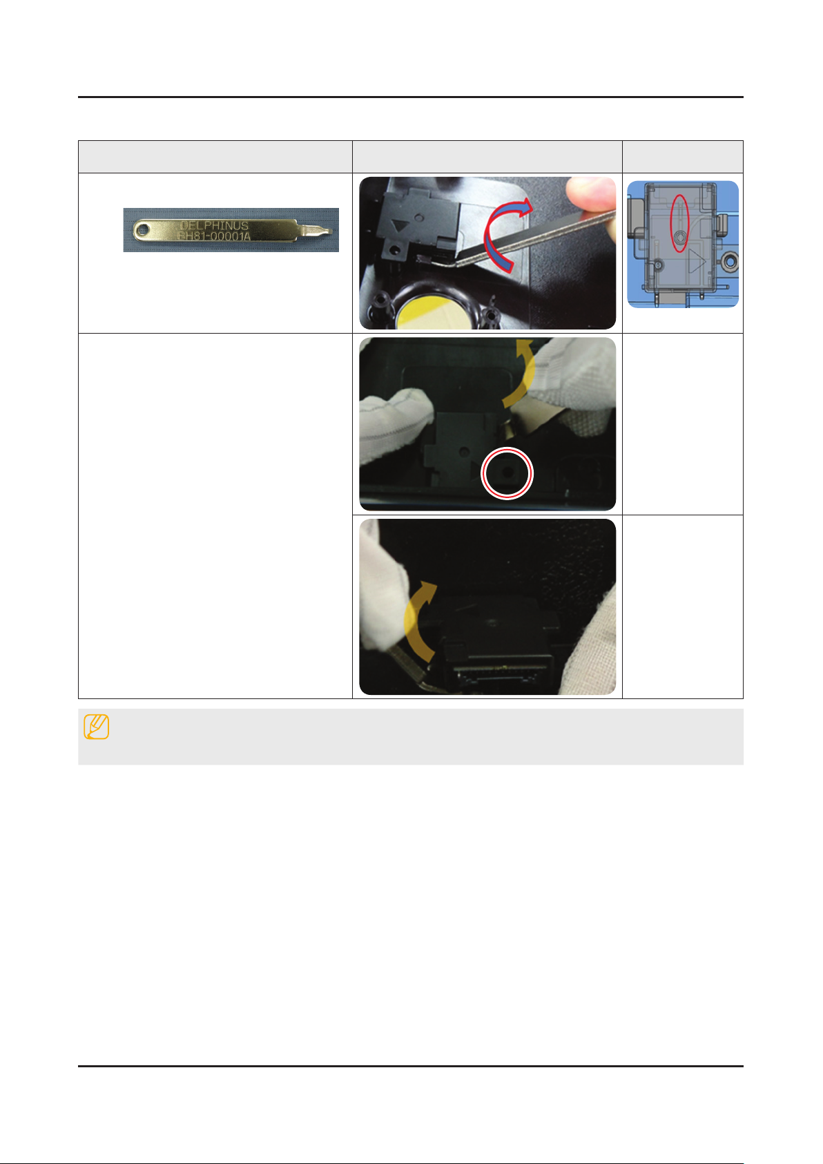
3-1-2. ASSY BOARD P-RF-MODULE
Description Picture Description Refer
Preparation : BN81-00001A (Registered in
1
Jig material)
Twist the jig after inserting ASSY BOARD
2
P-RF-MODULE(B/T module) and ASSY
COVER P-MIDDLE,REAR.
NOTE
Reassembly procedures are in the reverse order of disassembly procedures.
3-10
 Loading...