

Page 1
3-3. Trouble shooting
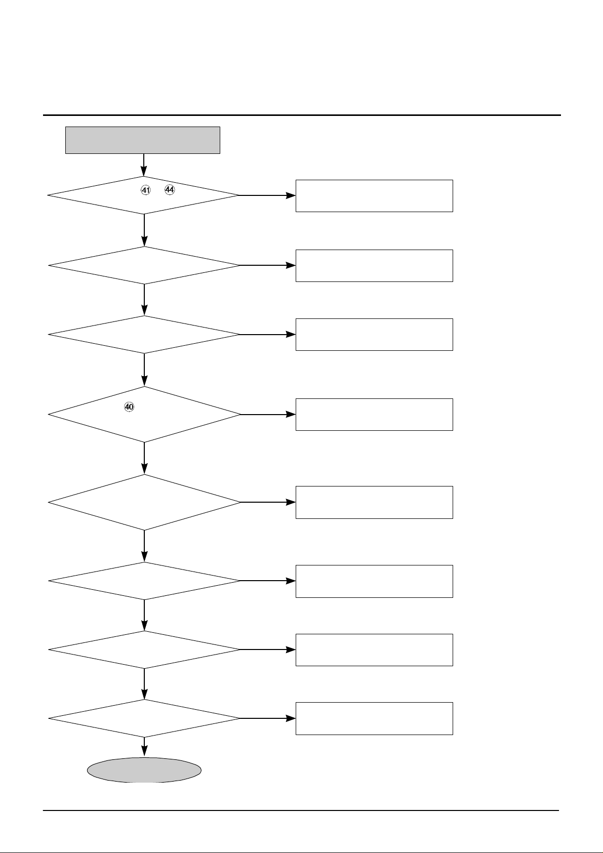
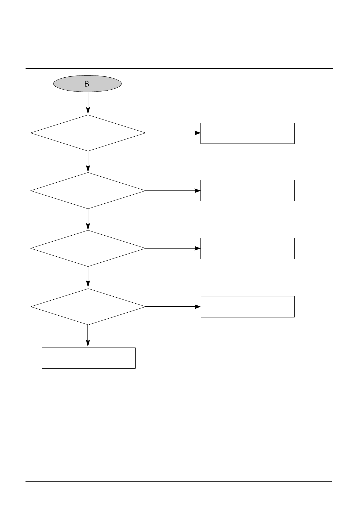
Power and initial stste check
Check CN1-2 +5V, +12V
after power cable connection
Y
IX1, MX1, SX1
oscillate
Y
MIC1 64pin change from
OV¡æ5V?
Y
SIC1 pin change
from OV to 5V?
(Check after connecting only power cable w ith
out IF cabl e connection)
N
N
N
N
Check power shoot, power supply
IIC1,MIC1,SIC1 power input are
normal, replace IX1, MX1, SX1
IIC3 9,10pin change
fromOV to5V
MIC1 power input
Y
PICK-UP moves in at power on
after moving out?
Y
TRAY open/close run?
Y
Laser diode is ON?
Y
FOCUS UP/DOWN run?
Y
N
N
N
N
See¡®SLED operation errow'
See¡®No TRAY open/close¡¯
See¡®No Laser diode on ¡¯
See¡®SERVO operation errow¡¯
Samsung Electronics
A
3-9
Page 2
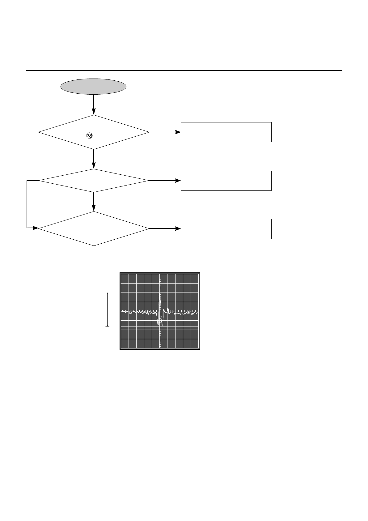
Toubleshooting
A
Y
<For DVD>
Focus lock runs?
SIC1 pin "OV"
Y
Dise rotates?
Y
<For CD>
Temporary stop state?
(TEsignal check)
N
See 'SERVO operation error'
N
See 'Disc rotation error'
N
See 'SERVO operation error'
2V
2.1V.
<TE signal at track jump>
(Temporary half state for DVD)
3-10
Samsung Electronics
Page 3
No tr ay open/close
Toubleshooting
Pin between MSW2 and MR22
OV at pressing MSW2
Y
OV sigal is inputted into MIC1
49pin at pressing MSW2
Y
OV, 5V switching signal of MSWI 3
pin is inputted into MIC1 47pin?
Y
OV,5V switching signal of MSWI 1
pin is inputted into MIC1 43pin?
Y
N
Check MSW2 slodering
N
Check pattern disconnection from
MR22 to MIC1 49 pin
N
Check MSW1 soldering and patten
N
Check MSW1 slodering and patten
Approx. ¡¾2V DC voltage come from
DICI 15,16 pin on the basis of 2.1V
at pressing Open/Close key?
Connection between CN4
and loading motor is normal?
Open/close runs normally.
Samsung Electronics
N
Check DR16, DR16A, DR17,
DR17A,DR18,DR18A soldering,
and If still not operated,
replace IC104.
Y
N
Check CN4 soldering and
wire disconnection state
Y
3-11
Page 4
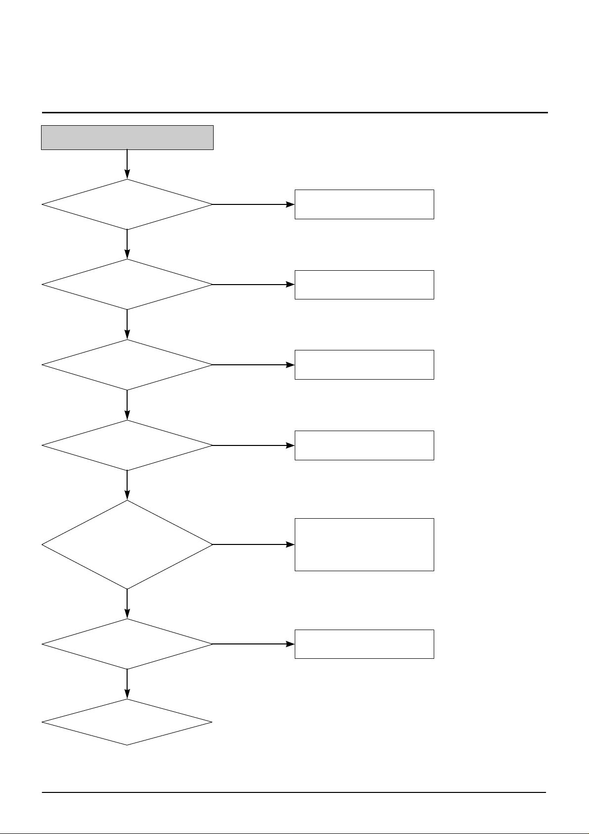
Troubleshooting
No la ser diode on
Focus up/down runs?
<For CD family>
Y<For DVD>
Power and GND terminal are
normal?
(5V:21,27,46,51,52pin
OV:1,55,66,76pin)
Y
RIC1 60pin is
about 2.9V?
Y
N
Check power and initial state
B
N
N
Check power and GND pattem
Check RR22 soldering
Voltage difference of
RR22 is approx. 800mV?
Y
RIC1 59 pin voltage is
approx. 20mV?
Y
Replace Pick-up.
N
RR21,RQ2,RL2 soldering
N
Check CN2 soldering
3-12
Samsung Electronics
Page 5
Troubleshooting
Power and GND terminal
RIC1are normal?
Y
RIC2pin is about 2.8V?
Y
Voltage difference between both
stages of RR2 is approx. 800mV?
Y
N
Check power pattem connection
N
N
Check RRI soldering
Check RR2, RQ1,RL2 soldering
RIC1 3 pin voltage is
approx. 20mV?
Y
Replace Pick-up.
N
Check RR23 soldering
Samsung Electronics
3-13
Page 6

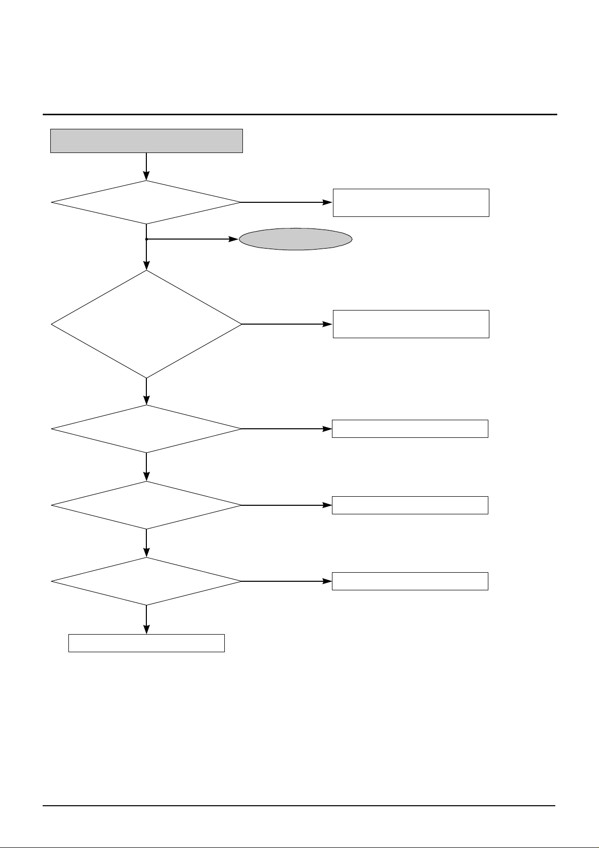
Troubleshooting
SERVO operation error
Insert disc
Y
Laser diode is on?
Y
Focus up/down runs?
Y
SIC138 pin is OV?
Y
Disc rotates?
Y
Track error siganl is inputted
into SIC1151 pin?
Y
C
N <For CD family>
<For DVD>
N
N
See 'No laser diode on'
D
N
E
N
See'No disc rotation'
Check soldering around SIC1
Y
E.F signal input in RIC1
79,80 pin and CN 2 connection
state are normal?
Y
N
3-14
N
DPD track error
siganl is oututted from
RIC133pin?
N
Check soldering
of SIC1 151pin
Replace RIC1
Check CN2 and RIC1colderingIf
still continued, replace Pick-up.
N N
A,B,C,D signalis
inputted into RIC1
67,68,69,70pin?
Y
Check RIC1 soldering
For no error,
replace RIC1
Check CN2. For no
error, replace Pick-up
Samsung Electronics
Page 7

Troubleshooting
C
Tracking driving signal is
outputted from SIC1
159pin(TRO)?
Y
Tracking driving signal is
outputted from DICI11,12pin
on the basis of 2.5?
Y
Connection state between
CN1,4 pin and
DIC1 11,12 pin is normal?
Y
N
F
N
N
Check pattern from SIC1 159 pin to
DICI 6,7 pin and replace DICI
CN2 soldering and pattern
between CN2 and DIC1
Resistance between 1 and 4
pin is about 6.2§Ùafter removing
FPB connected with Pick-up
from CN2 connector?
Y
Check pattem and sodering between CN104 1,2pin and SIC5 17,18pin Check FPC connection
sensor PCB check connection state between Feed Motor and spindle Motor and CN3
state between CN104 and CN1 of Hall
Samsung Electronics
N
Replace Pici-up
3-15
Page 8

Troubleshooting
3.3V: 5,12,16,33,59,78,89,116,138,144,160pin
D
Power and GND of SIC1
are normal?
5V:54,74,95pin
OV:3,8,9,17,22,61,66,83,105,110,
122,127,149,154,171pin
Y
N
Check SIC1 soldering For no error, see
'Power and initial state check'
430mV
SIC1 40pin changes from OV to
5V at power connection?
Y
Digital signal is inputted into
SIC1 41,42,43,44,46,47,48,49,50,51,52,53pin
Y
SIC1 158pin(FOO)output.
(Focus up.down driving signal)
N
N
See'Power and initial state check'
Check CN2 soldering and
check pattem between CN2 and DICI
N
Replace SIC1
3-16
Y
D-1
Samsung Electronics
Page 9

D-1
Toubleshooting
Focus up/down driving signal
is outputted from DIC1,13,14pin on the
basis of 2.5V?
Y
Pattem between CN2 2,3pin
and DICI13,14 pin and connection state
between CN2 and
FPC B of Pick-up is normal?
Y
Resistance between 2 and 3
pin is about 5.3§Ùafter removing FPCB
connected with Pick-up
from CN2 connector?
N
Check DR3,DR4,DIC1 soldering
For no error, replace DICI
N
Reconnect after removing Pick-up
FPCB and CN2
N
Replace Pick-up
For no error in focus actuator,
check connection of FPC B and
Samsung Electronics
Y
CN2 connector
3-17
Page 10

Troubleshooting
E
2V 2V..
Check SIC1 150pin
signal(Focus S-curve)
Y
RFSB signal goes up normally
when SIC1 152 pin is focused on?
N <For DVD>
N
<For CD family>
N
A,B,C,D signal is inputted normally in
RIC1 67,68,69,70 pin?
Y
RR10,RC20,SR65 soldering lf still
continued, replace IC101
A,B,C,D input are normal in
RIC1 72,73,74,75pin?
Y
Check RR9,RR9A,RC18,RC19
soldering lf still continued, replace RIC1
Check RIC1,SIC1 soldering
N
Replace RIC1
N
N
3-18
1V
Digital signal is normally
inputted in SIC1 41,42,43,
44,46,47,48,49,50,51,52,53pin?
Replace SIC1. lf error is
continued, replace Pick-up
Y
N
See 'Power and initial state check'
Y
Check Pick-up connection and FPCB contact lf
still continued, replace Pick-up
Samsung Electronics
Page 11

Troubleshooting
F
Sqare wave signal is inputted
in DIC2 39pin at spindle
motor rotation?
F
Y
sgare wave signdl is inputted
in SIC1 175pin at spindle
motor rotation?
Y
SIC1 38pin goes down from
OV to 5V after MIC1 5pin is
focused on?
Y
Replace SIC1
Check DIC2 peripheral soldering
If still continued, replace DIC2.
N
Check SIC1 peripheral soldering
N
Check pattem and soldering between
MIC1 5pin and SIC1 38pin
Y
RF signal inputted in
SIC1 142pin
See' RF signal check'
Samsung Electronics
N
Y
Check soldering around SC30, SC31
Y
lf still continued, replace RIC1
3-19
Page 12

Troubleshooting
Step Motor op erati on erro r
Move Pick Up to outside
Insert power code
<Supply PCB power>
Pick Up moves inside?
N
Signal is outputted from
MIC1 22,23 terminal?
Y
Signal is outputted from
DIC4 2,3,34,35 terminal?
Y
Check soldering CN3
Y
Check CN3 5,6 terminal connection
state and check 12V power
N
Check soldering MIC1
N
Check soldering DIC4 and
peripheral resoldering
3-20
Check Step Motor FPCB and
Step Motor
Samsung Electronics
Page 13

Disc rotation error
Troubleshooting
Sqare wave signal is outputted
in SIC1 183pin?
Y
DIC2 41pin is outputted 5V?
Y
CN3 17pin
approx. 800mV?
Y
N
Check digital signal is
outputted in SIC1
41~44pin, 46~53pin
Check soldering state SIC1. If
(If still continued, replace
SIC1
N
Check connection stste MIC1
24pin
N
Check soldering state DIC2
(If still continued, replace)
N
CN3 10pin is outputted 5V?
Y
N
Wave signal is outputted
in CN2 11~16pin when the disk
is rotated by hand?
Check FPCB connection state
between CN2 and SPINDLE MOTOR
Check soldering state DIC2.
(If still continued, replace)
Samsung Electronics 3-21
Page 14

Troubleshooting
RF si gnal check
RF signal is outputted
CN2 11pin?
Y
RF signal is inputted
RIC1 63,77pin°¡?
Y
RF signal is outputted
RIC1 45pin?
Y
RF signal is inputted
SIC1 142,143pin?
N
Check conection state
between PICK-UP and CN2.
If no error, replace PICK-
UP
N
N
Check soldering RC39, RC41
Check soldering RIC1 and
connection state SIC1 172,
173,174pin and
RIC1 14,15,16pin
N
Check soldering SC30, SC31
3-22
Samsung Electronics
Page 15

No au dio outpu t (on CDT)
Insert audio disc
Y
Troubleshooting
Servo runs normally?
Y
Audio signal is outputted
from SIC1 4,7
Y
Audio signal is outputted from
AICI 1,7 pin?
Y
Signal is outputted from headphone
jack or connector for audio output
in the back?
N
See 'Servo operation error'
N
5V is supplied to SIC1 54pin?
Y
Replace ic601
See 'Power and
N
initial state
check'
N
Check headphone volume and
AICI soldering
N
Check mute and soldering
AC8, AC5, AL1, AL2, AR21, AR20
Check headphone and audio cable
Samsung Electronics
Y
3-21
Page 16

Troubleshooting
Connect I/F cable of DVD-ROM and PC
Install error
Y
lnstall message comes out?
Y
MIC164pin is 5V at
power connection?
Y
MIC126pin is 5V?
Y
SX1, IXI oscillate?
Y
Digital signal between MIC1and MIC2 pattem
changes from OV to 5V?
Y
Digital signal between MIC1and MIC3 pattem
changes from OV to 5V?
N
Normal
N
N
See 'Power and initial state check'
N
N
Communication pattern disconnection
and MIC2 soldering
N
Communication pattern disconnection
and MIC3 soldering
3-22
Y
Digital signal between MIC1and IIC1 pattem
changes from OV to 5V?
Y
Communication signal of IIC1 and
IIC2is normal?
Y
Short and soldering exist between
IIC1 and CN1 pattem?
Y
Resoldering
N
Communication pattern disconnection
and IIC1 soldering
N
Communication pattern disconnection
and IIC2 soldering
N
Replace IIC1
Samsung Electronics
 Loading...