

Samsung SDC-9442DC User Manual
1080P Camera
User Manual
SDC-9442DC
CAUTION : Changes or modifications not expressly approved by the part responsible for compliance could void
the user's authority to operate the equipment.
NOTE : This equipment has been tested and found to comply with the limits for a Class A digital device, pursuant
to part 15 of the FCC Rules.
These limits are designed to provide reasonable protection against harmful interference when the equipment is
operated in a commercial environment.
This equipment generates, uses, and can radiate radio frequency energy and, if not installed and used in
accordance with the instruction manual, may cause harmful interference to radio communications.
Operation of this equipment in a residential area is likely to cause harmful interference in which case the user will be
required to correct the interference at his own expense.
PACKAGE CONTENTS
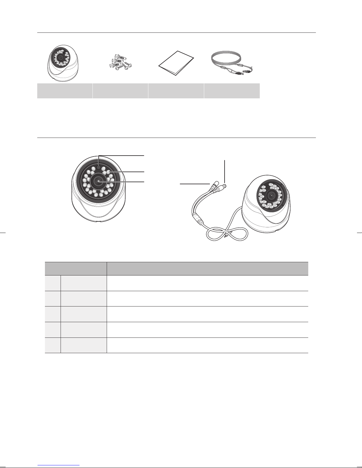
SDC-9442DC Plastic Achors / Screws User Manual Camera Cable (60ft)
PART NAMES
Name Description
Illumination Sensor
IR LED
b
Lens
c
b
c
Detects incoming light to control the IR LED.
These infrared LED's are controlled by the illumination sensor.
Focal length of 4mm enables you to cover relatively longer range of monitoring.
BNC Cable
Power Cable
BNC terminal for video signal output.
Used to plug the power cable.
2_ English
Precautions before installation
Ensure you read out the following instructions before installing the camera:
• It must be installed on the area (ceiling or wall) that can withstand 5 times the weight of the
camera including the installation bracket.
• Stuck-in or peeled-off cables can cause damage to the product or a fire.
• For safety purposes, keep anyone else away from the installation site.
And put aside personal belongings from the site, just in case.
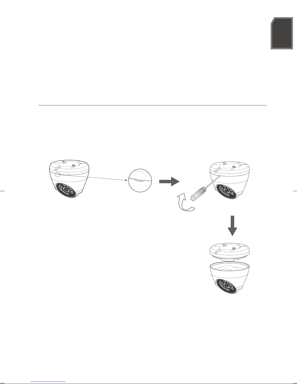
INSTALLATION
Disassembling
Insert a straight screwdriver into the slot and turn 45 degree to separate the bottom case and
fixed cover, as shown in the following picture. The width of the screwdriver is 3-6mm.
English
Slot
Turn 45 degree
English _3
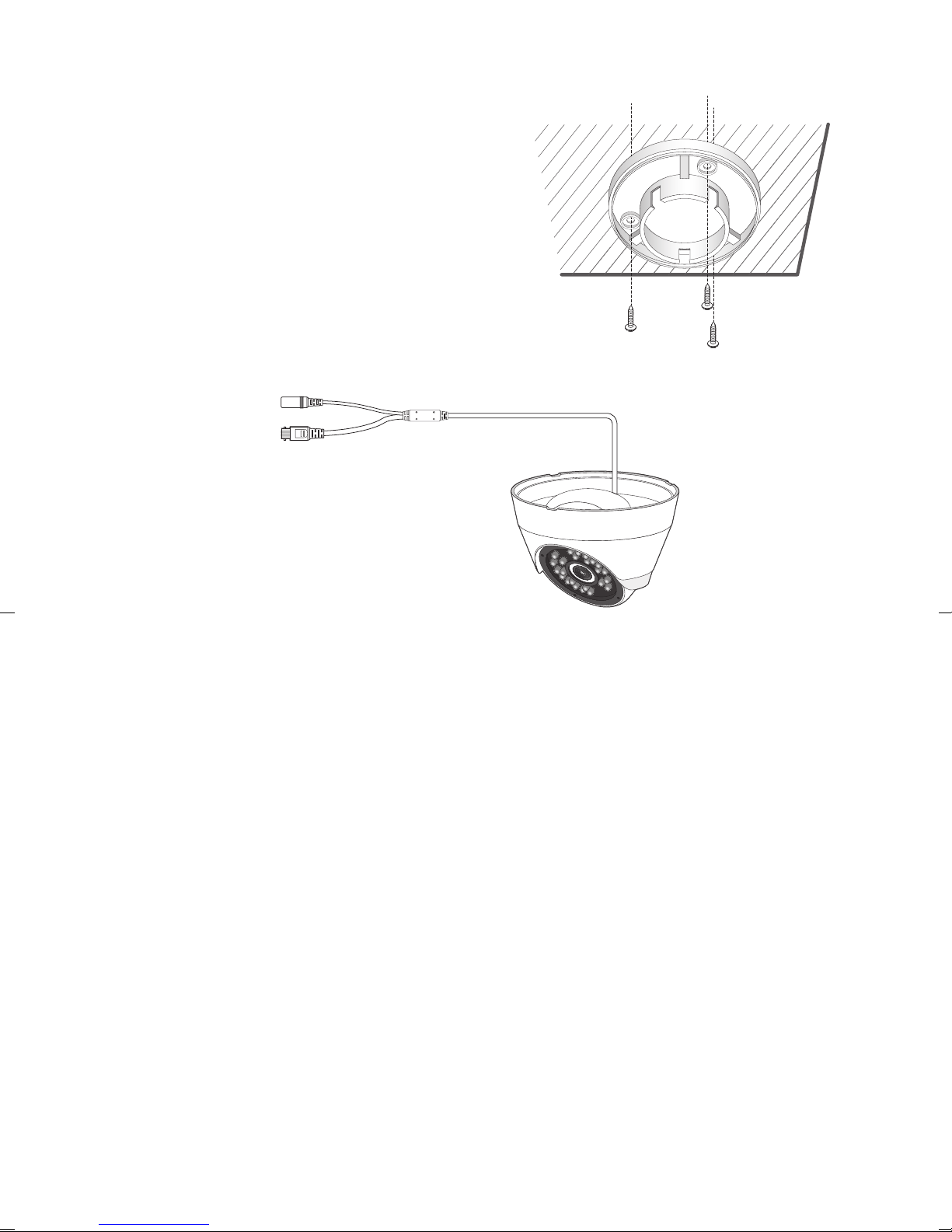
Installation
1. Select the installation area and mount the camera
base onto the wall or ceiling with 3 attached
screws.
2. Connect the power cable for camera.
3. Adjust the monitoring direction of the camera to make it face the monitoring area.
4.
Mount the protective cover of the camera and the main body on the wall bracket, as shown in
the picture.
Pay attention to the assembly direction. The gap direction of wall bracket faces the monitoring direction.
J
It is suggested that not to touch the lens during installation, as the camera lens focus has been adjusted
correctly in the final manufacturing process. If you touch the lens, the lens may be stained and fail to be
focused.
4_ English
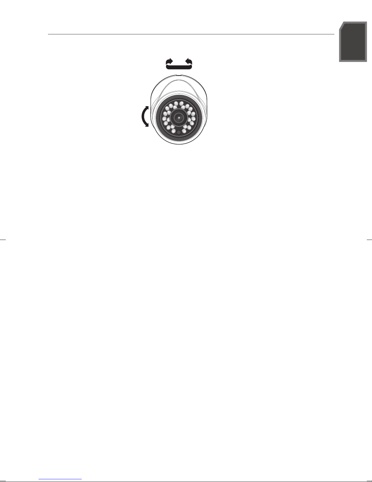
ADJUSTING THE MONITORING DIRECTION FOR THE CAMERA
Pan
Horizontale-Verticale
Adjusting the monitoring direction
You can adjust the camera direction only when the camera is fixed on the ceiling.
When you rotate the camera main body to the left or right is called Panning. And adjusting the
slope is called Tilt.
English
The effective range of pan is -15~ +15 degrees.
The effective range of tilt is 0~70 degrees.
The effective range of rotate is 0~ 350 degrees.
-
The image can be covered up by the camera case depending on the angle.
J
Methods of adjustment
1. After installing the camera, adjust the panning angle in consideration of the monitoring
direction.
2. Set the horizontal angle so that the image is not reversed.
3. Adjust the tilt angle so that the camera faces the monitoring object.
English _5
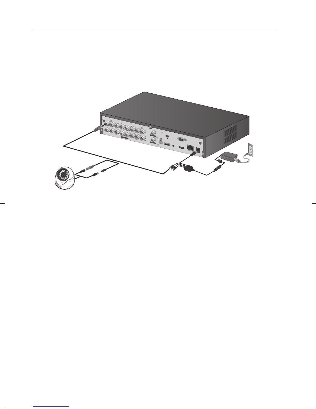
CONNECTING THE DVR
If you use a 1080P High Resolution camera with the IR LED and a lighting sensor, you can perform monitoring at
night as well as day.
SDC-9442DC 1080P High Resolution Camera is compatible with the following Samsung DVRs.
(SDR-C75300 / SDR-C74300/ SDR-B73300)
Connect the camera to the VIDEO IN port on the back of the DVR as shown below. Separate power adapter is
not needed to power the camera
The camera is suitable for both internal and external use.
VIDEO IN
AUDIO IN
AUDIO OUT
+-
RS485
VGA
USB
CONSOLE
HDMI
POWER
LAN
DC 12 V
6_ English
English
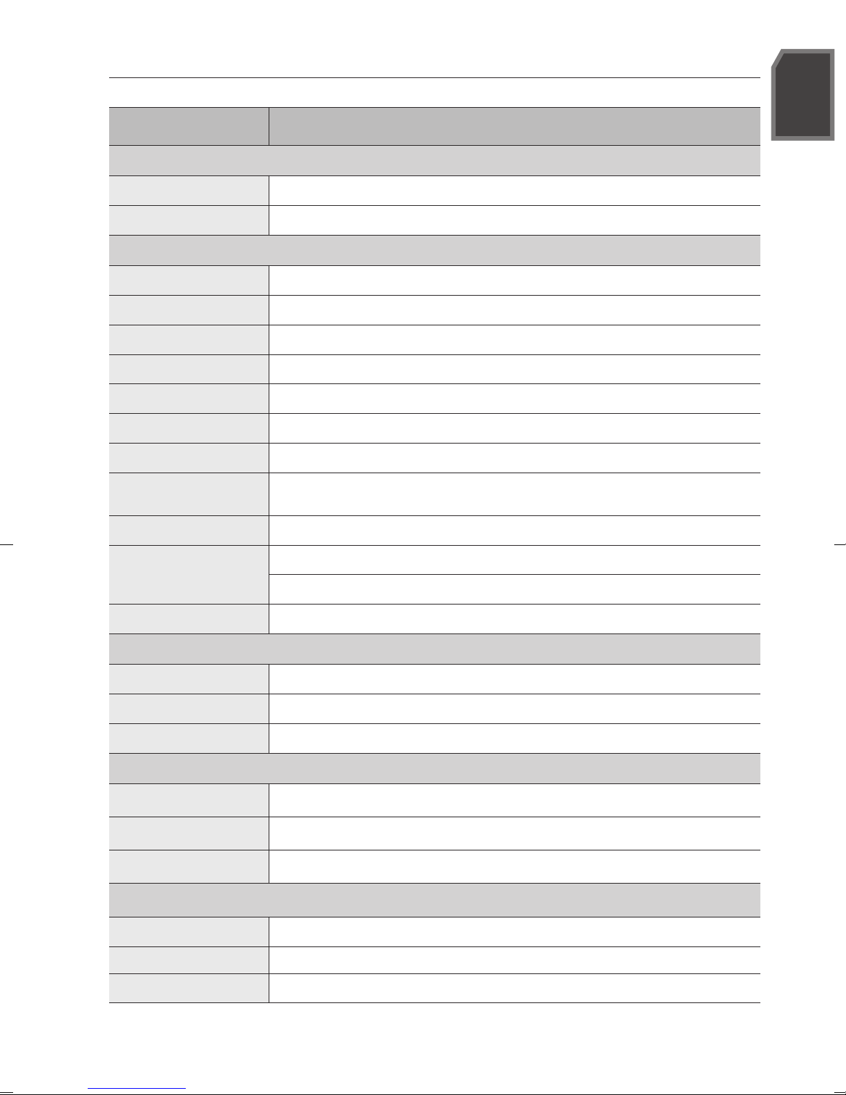
PRODUCT SPECIFICATION
Item Details
Electrical
Input Voltage
Power consumption
Video
Imaging Device
Resolution
Horizontal Resolution
Scanning System
Synchronization
Total Pixels
Active Pixels
Number of recommended
recording pixels
Min. Illumination
Camera Output
DC 12V
3.7W
2M CMOS (1/2.9")
1920 x 1080
Color : 900 TVL ,B/W : 900 TVL
Progressive, 30fps(NTSC)/25fps(PAL)
Internal
2000(H) x 1121(V) approx. 2.24M pixels
1936(H) ×1097(V) approx. 2.12M pixels
1920(H) ×1080(V) approx. 2.07M pixels
0 Lux (IR LED ON)
1CH BNC
Maximum Transmission Length: Over 300m (75Ω 3C2V)
Accessory Cable Length
Lens
Focus Length
Max.Aperture Ratio
Angular Field of View
Pan/Tilt
Pan range
Tilt range
Rotate range
Operational
Shutter Mode Auto (Rolling Shutter)
Gain Control Auto
White Balance Auto (1800K~10500K)
60ft (18.3m) included
4mm
F 2.1
H:72.2°, V: 52.9° (tolerance range ± 6%)
-15 ° ~ +15 °
0˚~ 70˚
0˚~ 350˚
English _7
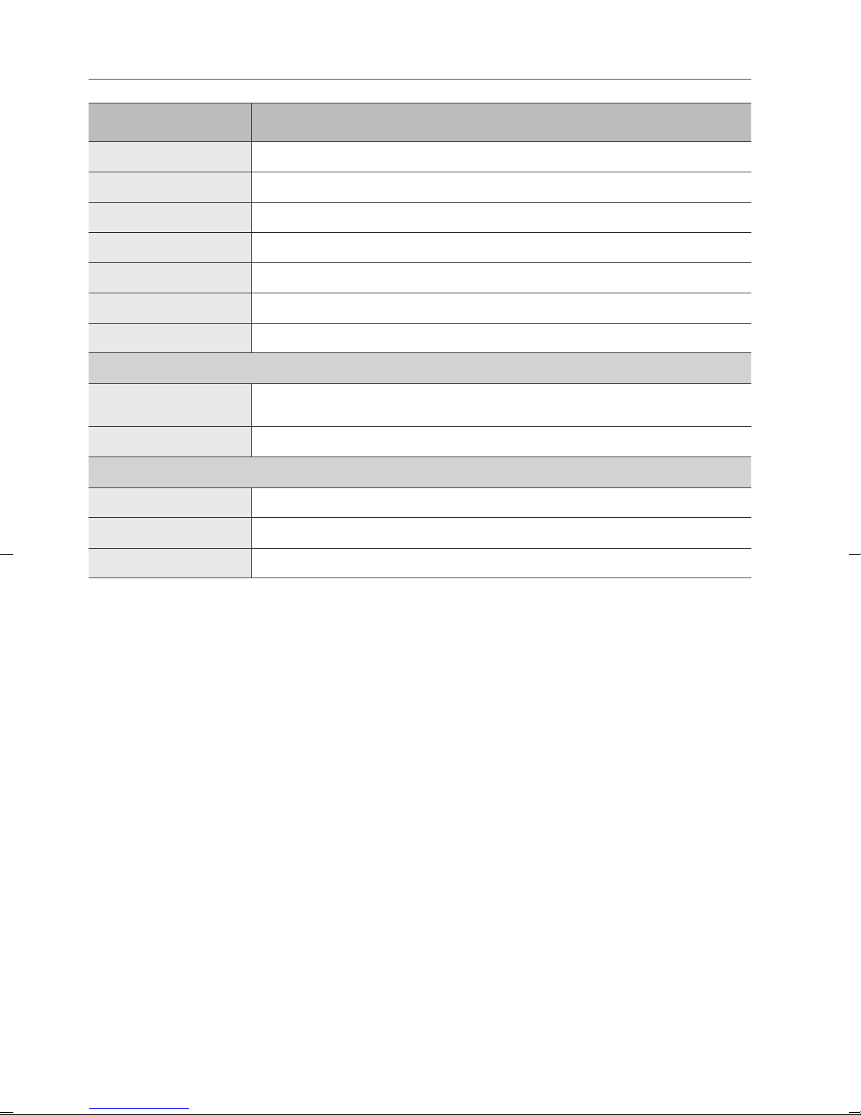
PRODUCT SPECIFICATION
Item Details
Wide Dynamic Range
Contrast Enhancement
Digital Noise Reduction 3D DNR
OSD N/A
Flickerless Auto
Day & Night TRUE D/N, Auto
IR Distance
Environmental
Operating Temperature /
Humidity
Ingress Protection
Appearance
Color / Material
Dimension (ØxH)
Weight
N/A
N/A
15m
-10°C ~ +50°C (+14°F ~ +122°F) / Less than 90% RH
IP66
Front:White/ADC12, BODY:White/ADC12, COVER:White/PC
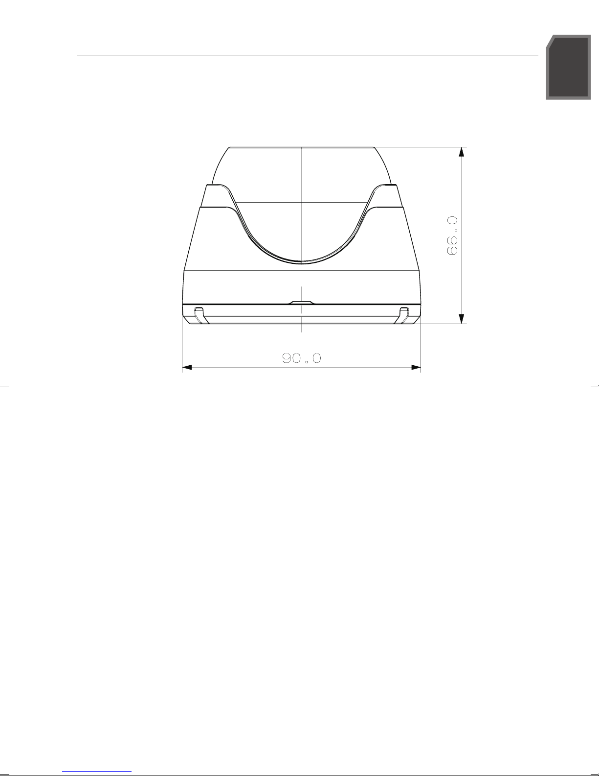
Φ90 Х 66mm
205g
8_ English
English
DIMENSION
UNIT: mm
English _9
This equipment has been tested and found to comply with the limits for a Class A digital device,
pursuant to part 15 of the FCC Rules. These limits are designed to provide reasonable protection
against harmful interference when the equipment is operated in a commercial environment.
This equipment generates, uses, and can radiate radio frequency energy and, if not installed and used
in accordance with the instruction manual, may cause harmful interference to radio communications.
Operation of this equipment in a residential area is likely to cause harmful interference in which case
the user will be required to correct the interference at his own expense.
Samsung cares for the environment at all product manufacturing stages, and is taking measures to provide
customers with more environmentally friendly products.
The Eco mark represents Samsung’s devotion to creating environmentally friendly products, and indicates that the
product satisfies the EU RoHS Directive.
Correct Disposal of This Product
(Applicable in the European Union and other European countries with separate collection systems)
This marking on the product, accessories or literature indicates that the product and its electronic accessories (e.g.
charger, headset, USB cable) should not be disposed of with other household waste at the end of their working life.
To prevent possible harm to the environment or human health from uncontrolled waste disposal, please separate
these items from other types of waste and recycle them responsibly to promote the sustainable reuse of material
resources.
Household users should contact either the retailer where they purchased this product, or their local government
office, for details of where and how they can take these items for environmentally safe recycling.
Business users should contact their supplier and check the terms and conditions of the purchase contract. This
product and its electronic accessories should not be mixed with other commercial wastes for disposal.
(Waste Electrical & Electronic Equipment)
10_ English
 Loading...