

Page 1

3-1Samsung Electronics
3. General information
3-1-1 Circuit description
3-1-1. Front
ROM
3-1-2. Rear
Figure 3-1
Figure 3-2
Earphone
jack
Up/Down
Volume
LED
Disc
tray
Emergency
HOLE
Stop/Open
button
Digital output
terminal
(Optional)
Sound output
terminal
Master/Slave
select pin
Interface terminal
Power terminal
Page 2

3-2 Samsung Electronics
3-2. Circuit description
3-2-1. RF
3-2-1(A) IC101 (TA1313F)
IC101(TA1313F) is used in combination with TC9489F as bipolar IC developed for CD/DVD RF signal system. In main, it
receives the pick-up output converted into I/V and preforms DVD waveform equalization(EQ), CD equalization(EQ),
astigmatic focus error signal generation, 1-beam tracking error signal generation(by DPD method), 3-beam tracking error
signal generation FE, TE, RF GAIN adjutment and laser power control, etc.
1) Reference potentiometer
IC101 selects a single power method and from pick-up input singnal terminl works on the basis VrA of 2.1.V.
2) CD/DVD-RF signal system: IC101(TA1313F)
Figure 3-3 shows the flow of RF signal generated in pick-up.
EQ control parameter
1. EQF(58pin): Change the peak frequency with EQ frequency features.
(Convert PWM signal, (TC9489F(168-pin) into DC via low-pass fiter and supply it.)
2. EQB(57pin): Change the boost of EQ frequency features.
3. VRCK(17pin):Input the base clock and link the peak frequency with it.
Figure 3-3
Page 3

3-3Samsung Electronics
3-2-2 SERVO circuit description
3-2-2(A) Outline
SERVO system of DVD is divided into FOCUS SERVO, TRACKING SERVO, STEP MOTOR LINKED SERVO and
SPINDLE MOTOR CONTROL SERVO.
1) FOCUS SERVO
Focus the optical spot outputted from object lens on disc surface correctly by maintaining a regular distance between
object lens of Pick-up and disc for surface vibration of disc.
2) TRACKING SERVO
Make the object lens follow the disc track in use of tracking error signal created from Pick-up.
3) STEP MOTOR LINKED SERVO
When the tracking actuator inclines to outer as the object lens follow the track at play, move STEP motor a little. and
prevent it from leaning.
4) SPINDLE MOTOR CONTROL SERVO
Control the disc motor to maintain a constant angular velocity in use of FG signal outted in Drive IC.
Page 4
3-4 Samsung Electronics
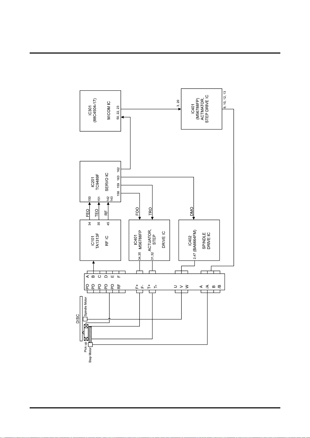
3-2-2(B) SERVO SYSTEM BLOCK DIAGRM
Circuit description
Figure 3-4
Page 5

Samsung Electronics 3-5
3-2-2(C) OPERATION DESCRIPTIONS
Circuit description
1) Focusing SERVO
(1) Focus input
The focus loop is changed from open loop to close loop. The triangular waveform moves the object lens up and down
in 158pin terminal of IC201 at Focus SERVO ON. At that time, S curve is inputted to 150 pin terminal of IC201.
SBAD(152pin terminal of IC201) signal, summing signal of PD A, B, C, D, is gernerated at occurrence of S curve and
zero cross(1.7V) point is found by S curve and focused on when SBAD signal exceeds a regular value.
The focus loop is changed into close loop and the object lens follows the moving of disc, maintaining a regular
distance with disc. While, this operations are same in CD and DVD.
(2) Play
When focus loop gets to close loop at focus servo on, both 150pin and 158pin terminal of IC201 are contoled by Verf
voltage(approx. 1.7V) and focus on cascade on the disc up and down.
158pin terminal of IC201(FOO)
150pin terminal of IC201(FEO)
152pin terminal of IC201(SBAD)
Figure 3-5
Page 6

3-6 Samsung Electronics
Circuit description
2) TRACKING SERVO
NORMAL PLAY MODE
(1) For DVD
Make the signal outputted though PD A,B,C,D of pick-up, tracking error signal in use of phase difference of A+C and
B+D in IC101 and inputted to IC201 151(TED) terminal. This signal is outputted to IC201 159 terminal(TRO) via
digital equalizer and impressed to tracking actuator through IC401, IC201 159 terminal is controlled in Vref
(approx 1.7V) at normal play.
(2) For CD, VCD
Receive the signal outputted through E, F of Pick-up, from IC101, differently from DVD and make the tracking error
signal through IC101 33pin terminal.
SEARCH MODE
Search mode is divided into fine seek, moving the tracking actuator a little and coarse serch, moving much in use of
STEP motor. The coarse search will be described in STEP linked servo and now, the fine seek is explained shortly.
If the object lens is located near target, cut off the tracking loop and give the control signal as many as desired count
to move the tracking actuator via IC201 159pin terminal(TRO).
3) SLED LINKED SERVO
NORMAL PLAY MODE
During the play signal come from 162pin of IC201 where according to movement of the tracking actuator along the
track,
and the signal is turn into terminal 50 of micom.
COARSE SEARCH MODE
After making seek lead the track make search for ID, and check up the number of must-go-track, in case the
remaining track is within the extend of fine seek, move the fine seek to object track, In case pick up move in the long
distance, the step motor move to half-step use the profile of must-go velocity in micom(IC301).
4) SPINDLE MOTOR CONTROL SERVO
The FG is generated IC402 39terminal rotation of disk, and this signal is IC201 175terminal where is outputted
IC201
163terminal with ckeck up velocity.
This signal is supplied in IC402 21terminal where control velocity of rotation at disk. The disk is rotated standard
angular velocity(CAV FORM) without relations of the inside and the outside of circumference of pick up.
Page 7

Samsung Electronics 3-7
Circuit description
3-2-3 ATAPI interface circuit description(IC501 : TC9492F)
3-2-3(A) ATAPI
ATAPI is interface specification to add SCSI paket command to the interface of HDD and support DVD-ROM drive as
abbreviation of AT ATTACHMENT PACKET INTERFACE.
3-2-3(B) Interface operation introduction
Micom judges the command type, controls SERVO IC, reads data from disk, sends to IC501 interface IC and transmitts
them to host at receiving a command(READ, SEEK, etc) from host(computer). Especially, in case of READ command, it
stores the data read from disk in IC502 :DRAM(V53C16258HK25) before transmission to host.
CD-ROM disk
Data are transferred to interface IC(IC501:TC9492F) though servo(IC201:TC9489F), stored in memory after
decoding and error correcting and then sent to host.
DVD-VIDEO, ROM disk
Data are transferred to interface IC501 through copy protection Servo IC(IC201:TC9489F)after error correcting in
data processor and stored in memory before transmission to host.
Figure 3-6
MICOM
Page 8

Samsung Electronics3-8
Circuit description
3-2-3 ATAPI interface circuit description(IC501 : TC9492F)
For flash memory using model, the version may be changed by downloading the micom program in PC without
ROM replacement.
Utilize FROMDOS.EXE supplied separately as download program.
 Loading...