

Page 1
3-9Samsung Electronics
3-3 Trouble shooting
A
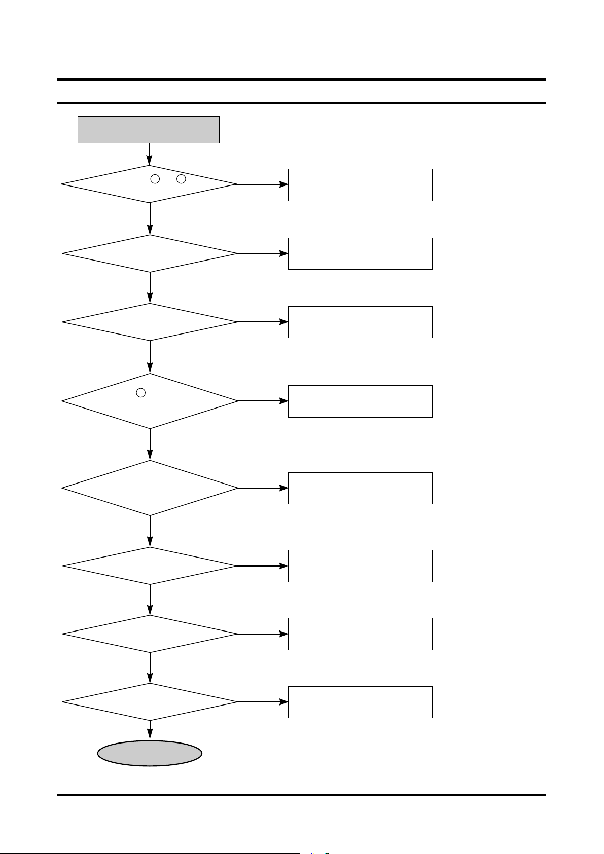
Check CN501-2 +5V, +12V
after power cable connection
Y
N
N
N
N
N
N
N
N
Y
Y
Y
Y
Y
Y
Y
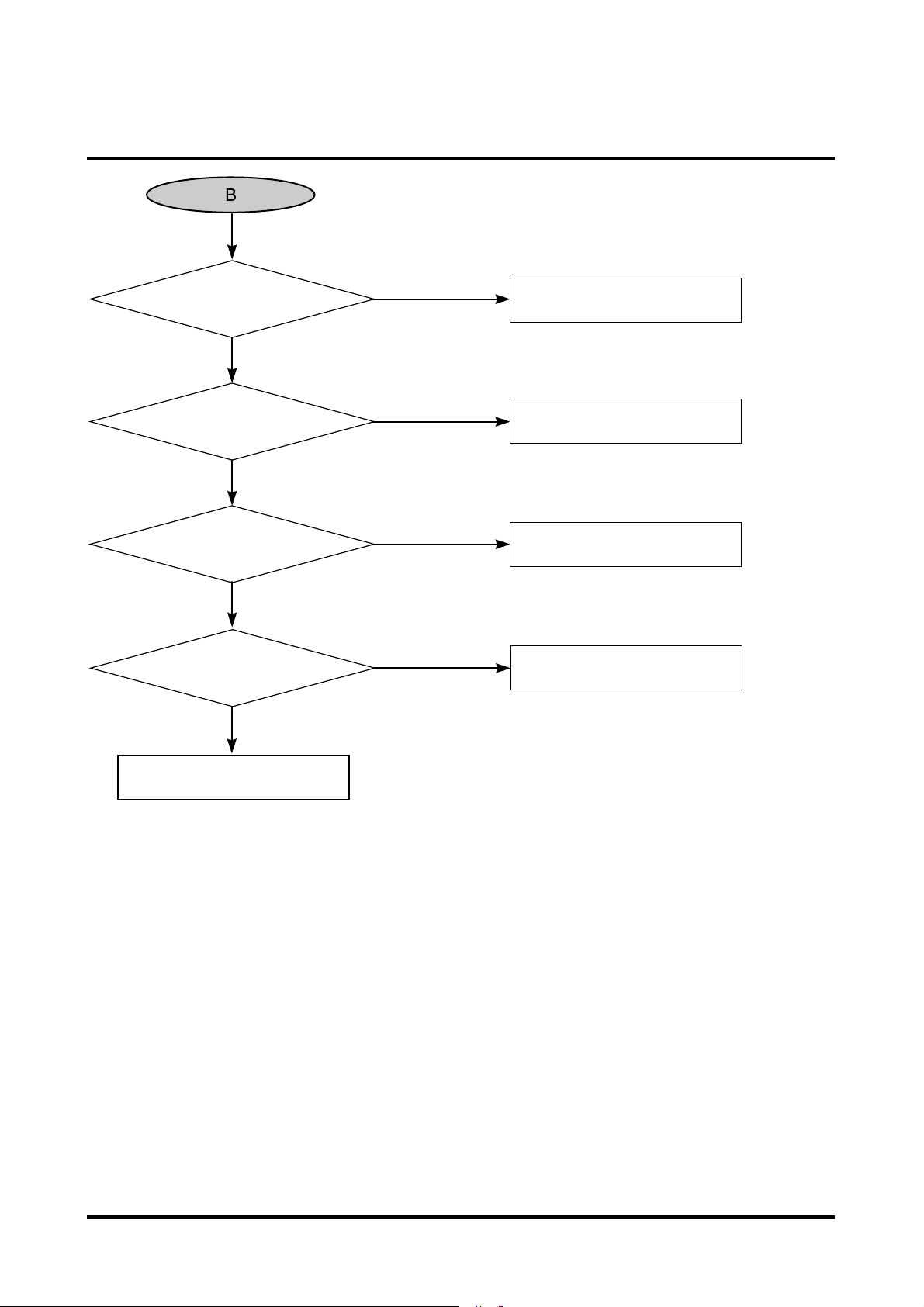
X501, X301, X201
oscillate ?
IC301 19 pin change from
0V to 5V?
Check power short, power supply
IC501, IC301, IC201 power input are
normal, replace X501, X301, X201
IC310 4,5pin change from
0v to 5v
IC301 power input
See ÔSLED operation errorÕ
See ÔNo TRAY open/closeÕ
See ÔNo Laser diode onÕ
See ÔSERVO operation errorÕ
IC201 pin change
from 0V to 5V?
PICK-UP moves in at
power on after moving out?
Tray open/close run?
Laser diode is on?
Focus up/down run?
Power and initial state check
(Check after connecting only power cable without IF cable connection)
41 44
40
Page 2
3-10 Samsung Electronics
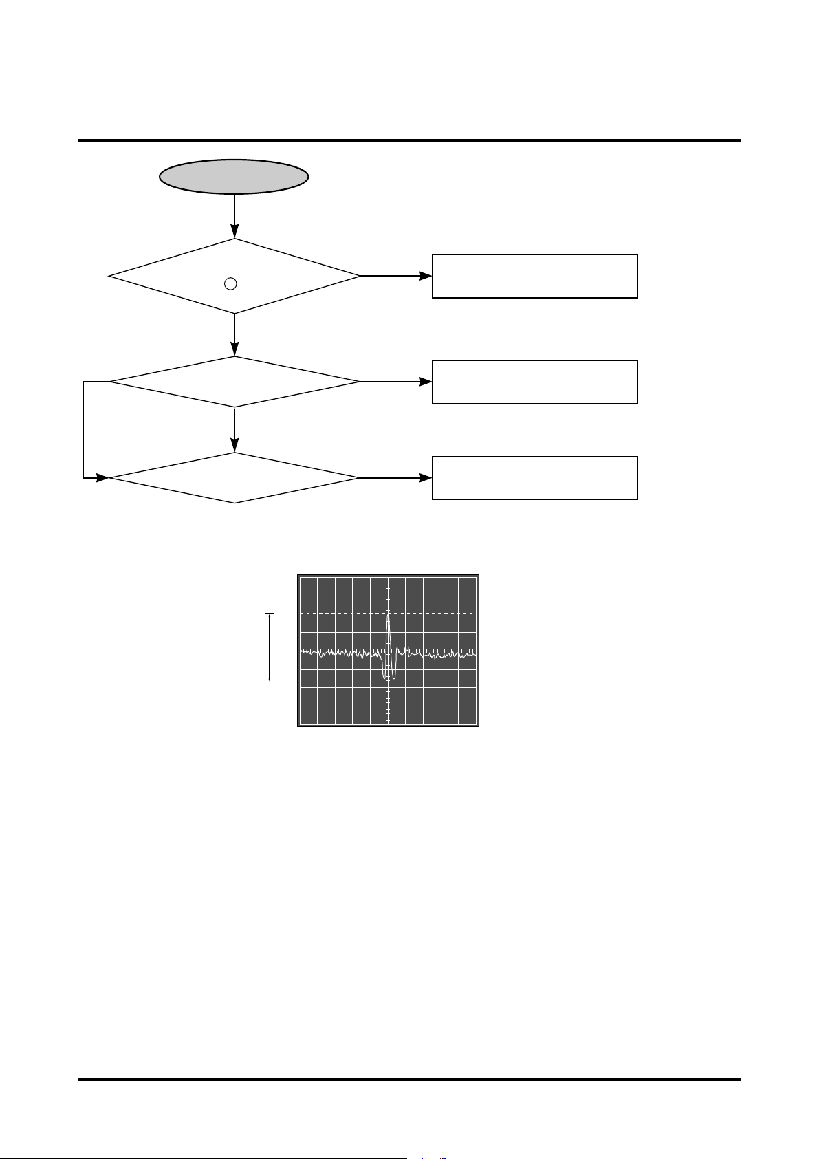
A
Focus lock runs?
(IC201 pin "0VÓ)
Disc rotates?
Temporary stop state?
(TE signal check)
See 'SERVO operation error'
See 'Disc rotation error'
See 'SERVO operation error'
<TE signal at track jump)
( Temporary halt state )
Y
Y
Y
N
N
N
2V 2.1V...
<For DVD>
38
Page 3
Samsung Electronics 3-11
No tray open/close
Pin between SW701 and R311
0V at pressing SW701?
Check the slodering of SW701
Check pattern disconnection from
R311 to IC301 41pin
Check the slodering of
SW702 and pattern
Check the slodering of
SW702 and pattern
Check the soldering of R405, R410,
R409,R404,R427and If still not
operated, replace IC401
Check the pattern, power of short
and wire disconnection state
0V signal is inputted into IC301
41 pin at pressing SW701?
0V, 5V switching signal of SW702
1pin is inputted into IC301 39pin?
0V, 5V switching signal of SW702
3pin is inputted into IC301 40pin?
Approx. ±2V DC voltage come from
IC401 14,15pin on the basis of 2.1V
at pressing Open/Close key?
Connection between IC401 14,15pin and
SW702 and loading motor is normal?
Open/close runs normally.
N
N
N
N
N
N
Y
Y
Y
Y
Y
Y
Page 4
3-12 Samsung Electronics
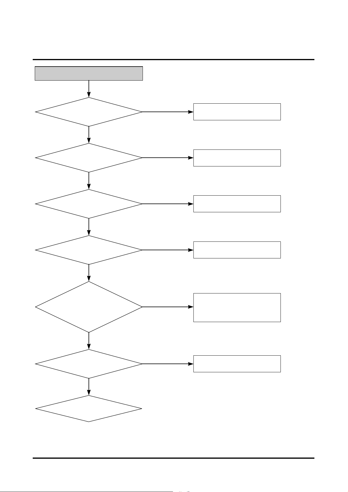
No laser diode on
Focus up/down runs?
Power and GND terminal of
IC101 are normal?
(5V : 21,27,46,52,65,71pin
OV:1,55,66,76 pin)
IC101 60pin is about 2.9 V?
Voltage difference of R103
is approx. 800mV?
IC101 59 pin voltage is
approx. 20mV?
Replace Pick-up.
Check power and initial state
Check power and GND pattem
Check the soldering of R106
Check the soldering of R103,Q101,L102
Check the soldering of CN101
N
N
N
N
N
Y
Y
Y
Y
Y
<For CD family>
<For DVD>
Page 5
Samsung Electronics 3-13
N
Y
Y
Y
Y
N
N
N
Power and GND terminal
IC101 are normal?
IC101 3pin is about 2.8 V?
Voltage difference between both
stages of R116 is approx. 800mV?
IC101 3 pin voltage is
approx. 20mV?
Replace Pick-up.
Check power pattern connection
Check the soldering of R115
Check the soldering of R116, Q102, L103
Check the soldering of R101
Page 6

3-14 Samsung Electronics
C
D
E
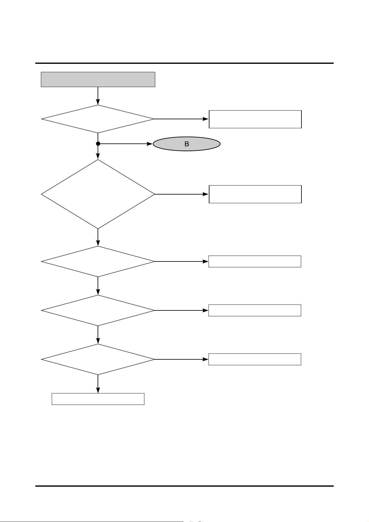
SERVO operation error
Insert disc
Laser diode is on?
Focus up/down runs?
IC201 38 pin is 0V?
Disc rotates?
Track error siganl is inputted
into IC201 151pin?
Check IC101 soldering
For no error,
replace IC101
See 'No laser diode on'
See 'No disc rotation'
E, F signal input in IC101
79,80 pin and CN101 connection
state are normal?
Replace IC101
Check the soldering around IC201
Check CN101 and IC101 soldering
If still continued, replace Pick-up.
Check CN101. For no
error, replace IC101
A, B, C, D signal is
inputted into IC101
67,68,69,70 pin?
DPD track error
siganl is oututted from
IC101 133pin?
N
N
N
N
N
N
Y
Y
Y
Y
Y
Y
Y
Y
N
Y
N
<For CD family>
<For DVD>
Check soldering of
IC201 151pin
Y
N
Page 7

Samsung Electronics 3-15
C
F
Tracking driving signal is
outputted from IC40I 31, 32 pin
on the basis of 2.5V?
Connection state between
CN101, 4 pin and
IC401 31, 32 pin is normal?
Resistance between 1 and 4
pin is about 6.2 ½ after removing
FPB connected with Pick-up
from CN101 connector?
Check pattern from IC201 159pin to
IC201 28,30pin and replace IC401
CN101 soldering and pattern
between CN101 and IC401
Replace Pick-up
N
N
N
Y
Y
Check connection state between Feed Motor
and spindle Motor and CN402
Tracking driving signal is
outputted from IC201
159 pin(TRO)?
N
Y
Y
Page 8

3-16 Samsung Electronics
D
D-1
Power and GND of IC201
are normal?
5V:54,74,95 pin 3.3V:5,12,15,16,19, 33,
36,59,78,89,116,138,141,144,160pin
OV:3,8,9,13,17,22,39, 61,66,75, 83,105,110,
122,127,149,154,171pin
IC201 40 pin changes from 0V to
5V at power connection?
Digital signal is inputted into
IC201 41,42,43,44,46,47,48,49,
50,51,52,53pin?
IC201 158pin(FOO) output.
(Focus up.down driving signal)
Check IC201 soldering For no error,
see ÔPower and initial state checkÕ
See 'Power and initial state check'
Check the soldering of CN101 and
check pattem between
CN101 and IC401
Replace of IC201
N
N
N
N
Y
Y
Y
Y
430mV
Page 9

Samsung Electronics 3-17
D-1
Check the soldering of R401, R403,
IC104 and For no error, replace IC401
Reconnect after removing Pick-up
FPC and CN101
Replace Pick-up
Focus up/down driving signal
is outputted from IC401 34, 35pin on the
basis of 2.1V?
Pattern between CN102 25, 27 pin
and IC104 13, 14 pin and connection state
between CN102 and
FPC of Pick-up is normal?
Resistance between 25 and 27
pin is about 12 ½ after removing FPCB
connected with Pick-up
from CN102 connector?
For no error in focus actuator,
check connection of FPC and
CN102 connector
N
N
N
Y
Y
Y
Page 10

3-18 Samsung Electronics
Check IC201 150pin
signal (Focus S-curve)
RFSB signal goes up normally
when IC201 152pin is focused on?
Digital signal is normally
inputted in IC201 41,42,43,44,46,47,
48,49,50,51,52,53 pin?
Replace IC201.
If error is continued, replace Pick-up
A, B, C, D signal is inputted normally into
IC201 67,68,69,70pin?
R111, C114, R223 soldering If still
continued, replace IC101
Check the soldering of IC101, IC201
Replace IC101,IC201
See 'Power and initial state check'
Check Pick-up connection and FPCB contact
If still continued, replace Pick-up
N
N
N
Y
Y
Y
Y
2V 2V...
1V
Y
N
A, B, C, D input are normal in
IC101 72,73,74,75 pin?
Check R112, R113, C115
soldering If still continued, replace IC101
N
<For DVD >
<For CD family>
N
N
Page 11

Samsung Electronics 3-19
F
Sqare wave signal is inputted
in IC402 24pin at spindle
motor rotation?
Sqare wave signal is inputted in IC201
175pin at spindle motor rotation?
IC201 38pin goes down from
0V to 5V after IC301 9pin is
focused on?
Replace IC201
See 'RF signal check'
Check IC402 peripheral soldering
If still continued, replace IC402.
Check IC201 peripheral soldering
RF signal is inputted into
IC201 142 pin?
Check
pattern
and soldering between
IC301 9pin and IC201 38pin?
Check the soldering around
IC201, IC101, and C220, C221
If still continued,
replace IC101
N
N
Y
Y
Y
Y
Y
N
Page 12

3-20 Samsung Electronics
Step Motor operation error
Move Pick-up to outside.
Insert power cord
<Supply PCB power>
Pick up moves inside?
Check the connection of CN401
state and check 12V power
Check the soldering of IC301
and No error replace of IC301
Check soldering IC401 and
peripheral resoldering
Signal is outputted from
IC301, 22,23 terminal?
Signal is outputted from
IC401, 9,10,12,13 terminal?
Check soldering CN402
Check Step Motor FPCB and
Step Motor
Y
N
N
Y
Y
N
Page 13

Samsung Electronics 3-21
Disc rotation error
Rectagular wave is outputted from IC201 ?
Check the Digital signal outputted
from IC201 41~44pin, 46~53pin.
Check the soldering of IC201 when
the no error and replace.
Check the connection state of
IC301 24pin.
After check the soldering of
IC402 and replace.
IC402 23pin is outputted 5V ?
IC402 17pin is outputted 800mV ?
IC402 4pin is outputted 5V ?
Check the connection of FPCB and
between CN403 and SPINDLE MOTOR
After check the soldering of
IC402 and replace
Wave form is out putted in
CN402 5~10pin when the
disc is rotated by hand ?
Y
Y
N
N
N
N
N
Y
Y
Page 14

3-22 Samsung Electronics
RF signal check
RF signal is inputted
from IC101 64 pin, 77pin?
RF signal is outputted into IC101 45pin?
Y
Y
N
N
N
After check connection state of F-PCB
between pick-up and CN101
and if no error replace of pick-up.
Check the soldering of C127and C125.
Check the soldering of IC101 and IC201
172pin, 173pin,174pin and connection
state of IC101 14pin, 15pin, 16pin .
Check C220, C221 soldering.
RF signal is inputted
from IC201142pin, 143pin?
Y
RF signal are outputted
from CN101 11pin?
Page 15

Samsung Electronics 3-23
No audio output (on CDT)
Insert audio disc
Servo runs normally?
Audio signal is outputted
from IC201 4,7pin
Audio signal is outputted from
IC701 1,7pin?
Check headphone and audio cable
Signal is outputted from headphone
jack or connector for audio output
in the back?
Replace is IC601
See ÔPower
and initial state
checkÕ
Check mute and soldering
C703, C705, L701, L702, R909, R910,
CE903, CE904
5V is supplied to IC201 54pin?
See ÔServo operation errorÕ
Check headphone volume and
IC70I soldering
Y
Y
Y
Y
Y
Y
N
N
N
N
Page 16

3-24 Samsung Electronics
Install error
Connect I/F cable of DVD-ROM and PC
Install message comes out?
IC301 19pin is 5V at
power connection?
IC301 26pin is 5V?
X201, X50I oscillate?
Digital signal between IC301 57~80pin
changes from 0V to 5V?
Digital signal between IC301 and IC302 pattern
changes from 0V to 5V?
Digital signal between IC301 and IC501 pattern
changes from 0V to 5V?
Communication signal of IC501
and IC502 is normal?
Short and soldering exist between
IC501 and CN501 pattern?
Resoldering.
Y
Y
Y
Y
Y
Y
Y
Y
Y
Y
N
N
N
N
N
N
N
N
Normal
Replace IC501
Communication pattern disconnection
and IC502 soldering
Communication pattern disconnection
and IC501 soldering
Communication pattern disconnection
and IC302 soldering
Communication pattern disconnection
and IC301 soldering
See 'Power and initial state check'
N
 Loading...