

Samsung SCX-5315F Series, SCX-5115 Service Manual
DIGITAL LASER MFP
SCX-5315F Series
SCX-5315F
SCX-5115
1. Precautions
2. Specifications
3. Disassembly
4. T roubleshooting
5. Exploded Views and Parts List
6. Block Diagram
7. Connection Diagram
DIGITAL LASER MFP
CONTENTS
SERVICE
MANUAL
Specification
Samsung Electronics
2-1
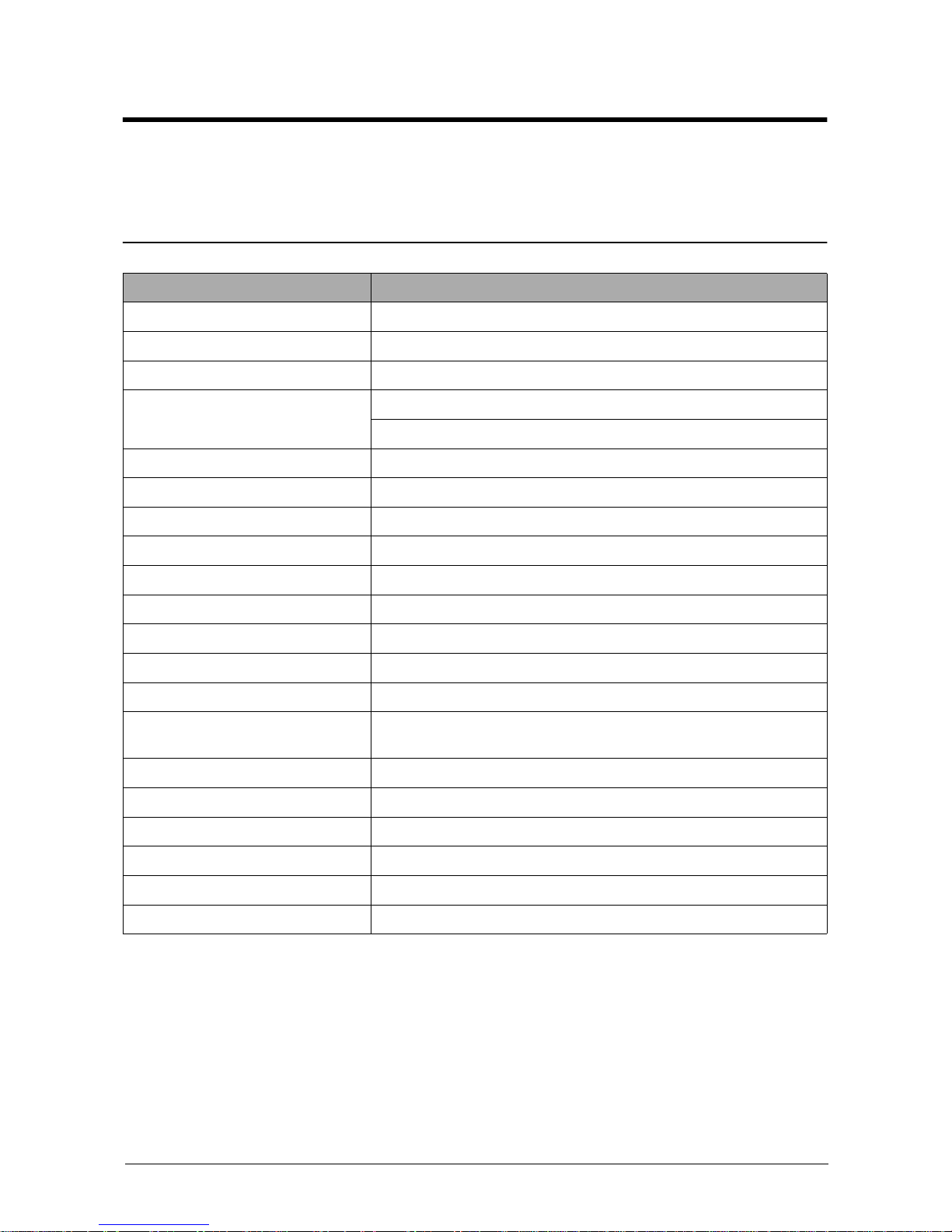
2. Specification
Specifications are correct at the time of printing. Product specifications are subject to change without notice.
See below for product specifications.
2-1 General Specifications
* Sound Pressure Level, ISO 7779
Item Description
Type of Unit Desktop
Operation System Win95/98/ME/ NT /2000/XP
Duplex Printing Yes(Default)
Interface IEEE1284(ECP)
USB(without HUB mode)
CPU 120 MHz(ARM946ES)
Emulation PCL6
Warming up Time 30 Sec (Stand-By), 25˚C
Absolute Storage Condition Temperature : -20°C ~ 40°C, Humidity : 10% RH ~ 95% RH
Operating Condition Temperature : 10˚C ~ 32˚C, Humidity : 20% RH ~ 80 % RH
Recommended Operating Condition Temperature : 16°C ~ 30°C, Humidity : 30% RH ~ 70% RH
Dimension(W X D X H) 560 X 433 X 459 mm
Weight About 22.5 Kg(with CRU)
* Acoustic Noise Less than 56/50 dB(Copy/Printing mode)
Power Rating AC 100VAC ~ 127VAC ± 15 %, 50/60Hz ± 3Hz
AC 220VAC ~ 240VAC ± 15 % , 50/60Hz ± 3Hz
Power Consumption Avg. 320Wh
Power Save Consumption Avg. 35Wh
Recommended System Requirement Pentium IV 1.2 Ghz, 128 MB RAM, 220MB(Hard Disk)
Minimum System Requirement Pentium II 400Mhz, 64 MB RAM, 120MB(Hard Disk)
LCD 16 characters X 2 lines
Memory 4 Mbyte for flash Memory , 16 Mbyte for SDRAM
Specification
Samsung Electronics2-2
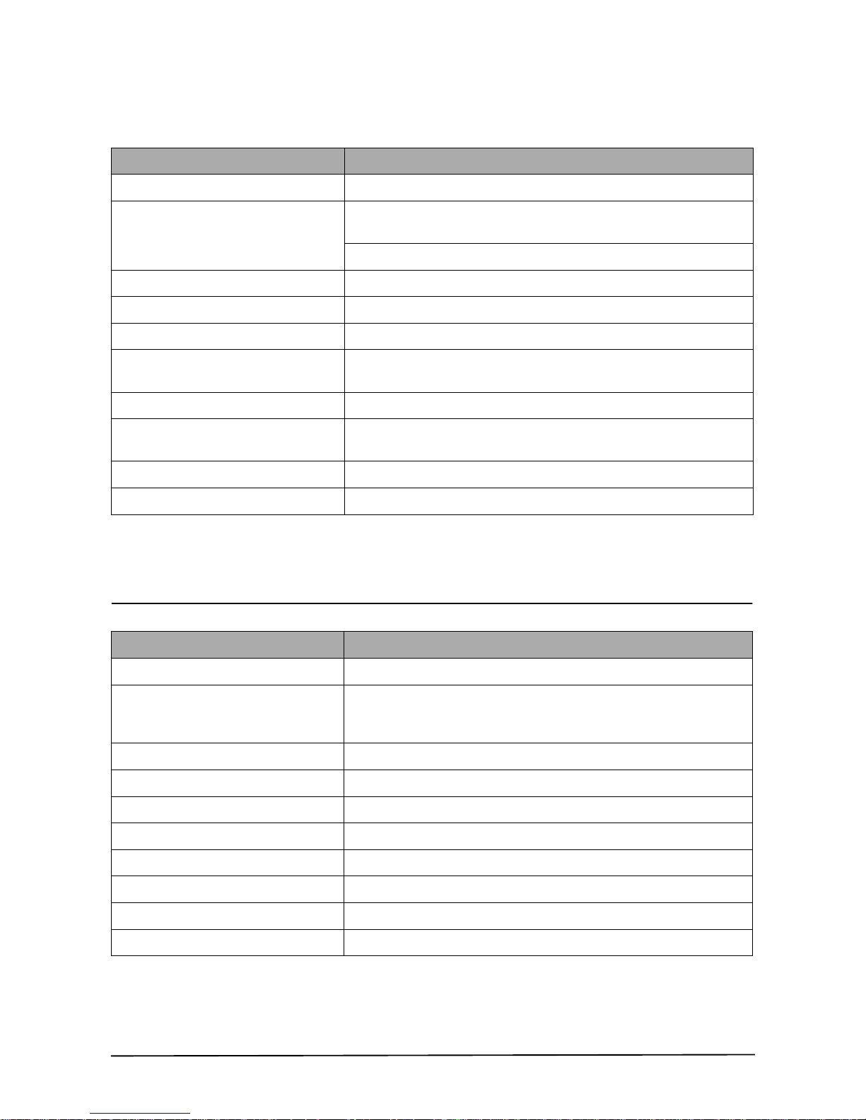
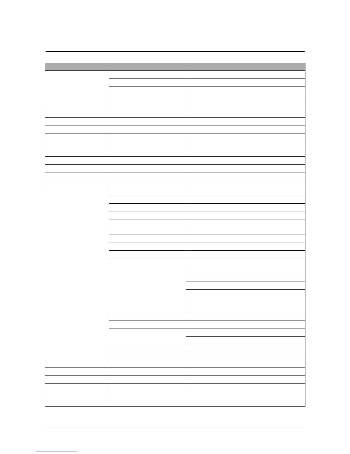
2-2 Printer Specifications
* Print speed will be affected by Operating System used, computing performance, application software,
connecting method, media type, media size and job complexity.
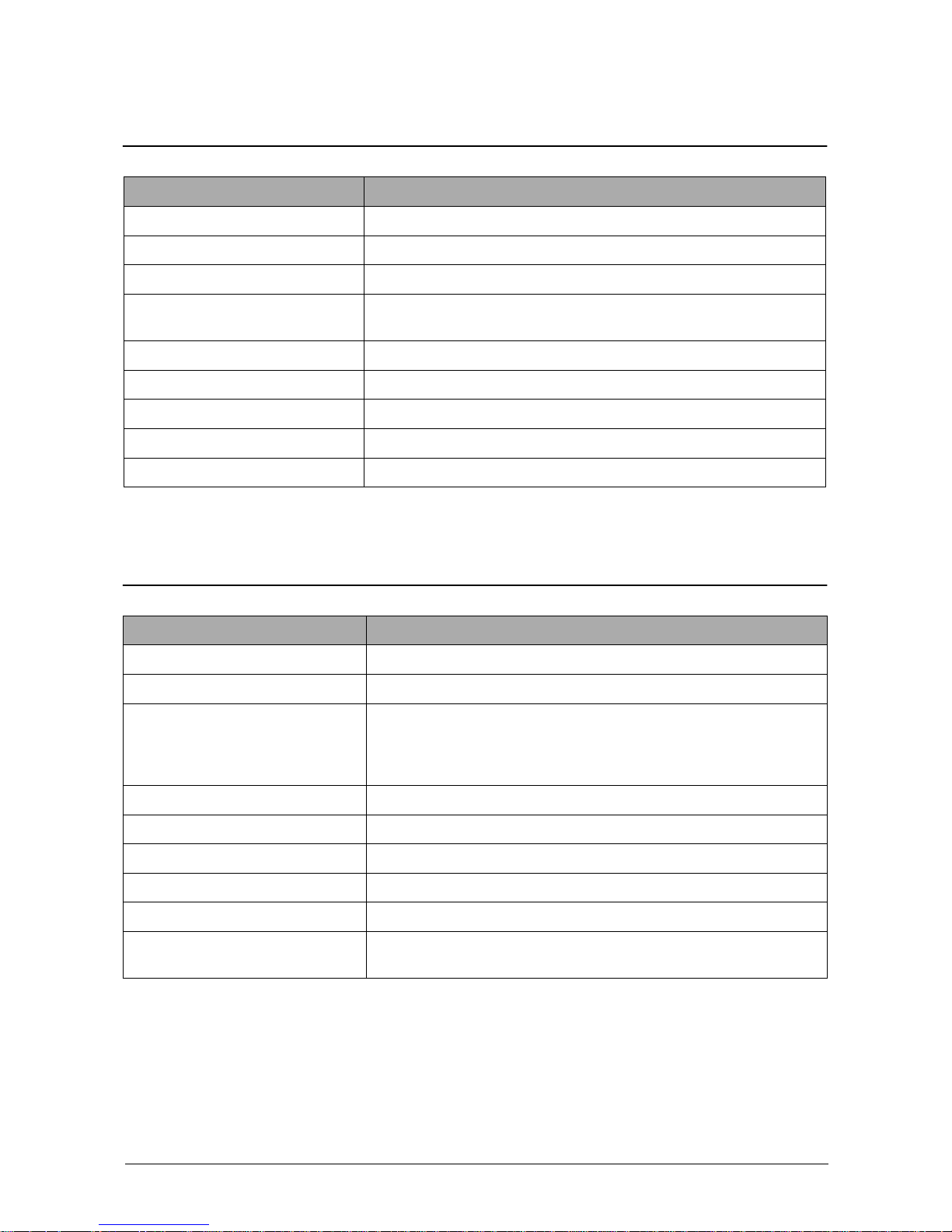
2-3 Facsimile Specification(SCX-5315F Only)
Item Description
Printing Method Laser Scanning Unit + Electro Photography
*Speed Single Side : Up to 15 PPM
(Letter Size, 5% Character Pattern)
Duplex : Up to 7.5 IPM(Images/Min) (Letter Size, 5% Character Pattern)
Source of Light LSU(Laser Scanning Unit)
Duplex Printing Yes(Default)
Resolution(Horizontal X Vertical) Up to 1200 x 1200 DPI effective output
Feed Method Cassette Type , By Pass Tray,
ADF(Automatic Document Feeder)
Feed Direction FISO(Front-In Side-Out)
Paper Capacity(Input) Cassette : 550 Sheets
By Pass Tray : 100 Sheets(based on 75g/ß
≥ , 20lb)
Paper Capacity(Output) Face Down : 250 Sheets
Effective Print Width 203 ± 1mm (8 inch)
Item Description
Standard Recommendation ITU-T Group3(ITU : International Telecommunications Union)
Application Circuit PSTN or behind PABX
(PSTN : Public Switched Telephone Network.
PABX : Private Automatic Branch Exchange)
Data coding(Compression) MH/MR/MMR/JPEG(Transmission)
Modem speed 33600 /14400/12000/9600/7200/4800/2400 bps
Transmission Speed Approximately 3 sec(33,600 bps)
Effective Scanning Width 8.2 inches(208 mm)
Halftone 256 Levels
Paper Capacity(Input) ADF(Automatic Document Feeder) : 30Sheets(75g/ß
≥ )
FAX Mode Standard /Fine/Super Fine/Halftone
Memory 4MB
Specification
Samsung Electronics
2-3
2-4 Scanner Specification
* Speed will be affected by Operating System used, computing performance, application software, connecting
method, media type, media size and job complexity.
2-5 Copy Specification
NOTE :
(1) Speed claims based on the test chart : Letter size.
SDMP : Single Document Multiple Printout
MDSP : Multiple Document Single Printout
• Speed will be affected by Operating System used, computing performance, application software,
connecting method, media type, media size and job complexity.
Item Description
Type Flatbed(with ADF)
*Speed Mono : Up to 1.2 msec/line, Color : Up to 2.5 msec/line
Device Color CCD(Charge Coupled Device) Module
Interface IEEE1284(ECP Support)
USB(without HUB Mode)
Compatibility TWAIN Standard , WIA
Optical Resolution(H X V) Up to 600 x 600 DPI effective output
Interpolation Resolution Max. 4800 dpi
Halftone 256 Levels
Effective Scan width 8.2 inches(208 mm)
Item Description
Mode B/W
Quality Text/Photo/Mixed
Mono Copy Speed
(1)
Platen(SDMP) : Up to 12 cpm in A4 size, IDC 5% pattern
ADF (SDMP) : Up to 12 cpm in A4 size, IDC 5% pattern
ADF (MDSP) : Text/mixed : Approx. 7 cpm in A4 size, IDC 5% pattern
: Photo : Approx. 3 cpm in A4 size, IDC 5% pattern
Optical Resolution (H x V) Up to 600 x 600 DPI effective output
Multi Copy 99 pages
Maximum Original Size Legal
Maximum Page Size Legal
Paper Type Selection Plain , Legal , Cardstock , Transparency
Zoom Range Platen : 25 ~ 400%(1% Step)
ADF : 25~100 %(1% Step)

Specification
Samsung Electronics2-4
2-6 Telephone Specification(SCX-5315F Only)
2-7 Consumables
Item Description
Speed Dial 80EA
Tone/Pulse Tone only user modeTone/Pulse selectable in tech mode.
Item Description
Type Separate type
(Toner Cartridge / Drum Cartridge)
Life Toner Cartridge Up to 6,000 sheets
( 5% coverage pattern, simplex normal mode )
Drum Cartridge Up to 15,000 sheets
(simplex normal mode )

T I D I
This service manual is also provided on the web,
the ITSELF system Samsung Electronics Co., Ltd.
“http://itself.sec.samsung.co.kr”
© Samsung Electronics Co.,Ltd. JULY 2003
Printed in Korea.
VERSION NO. : 1.00 CODE : JC-0086A
This Service Manual is a property of Samsung Electronics
Co.,Ltd. Any unauthorized use of Manual can be punished
under applicable International and/or domestic law.
Disassembly and Reassembly
Samsung Electronics
3-1
3. Disassembly and Reassembly
3-1 General Precautions on Disassembly
When you disassemble and reassemble components, you must use extreme caution.
The close proximity of cables to moving parts makes proper routing a must. If components are removed, any
cables disturbed by the procedure must be restored as close as possible to their original positions. Before
removing any component from the machine, note the cable routing that will be affected.
Whenever servicing the machine, you must carry out the following :
1. Check to verify that documents are not stored in memory.
2. Unplug the power cord.
3. Use a flat and clean surface.
4. Replace only with authorized components.
5. Take care when removing plastic component-do not force.
6. Make sure all components are in their proper position.
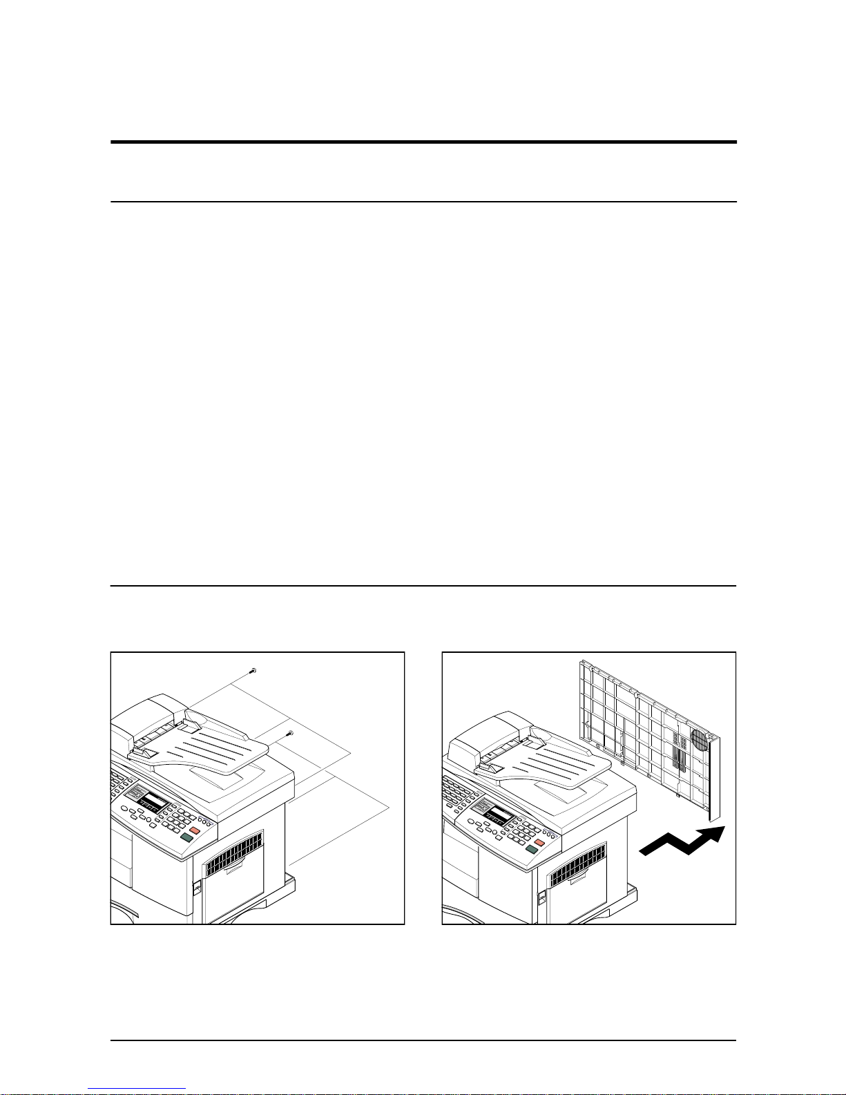
3-2 Rear Cover
1. Remo ve the six screws securing the Rear Cov er .
2. Separate the rear cover from the base frame
and Scanner Ass'y.
Disassembly and Reassembly
3-2
Samsung Electronics
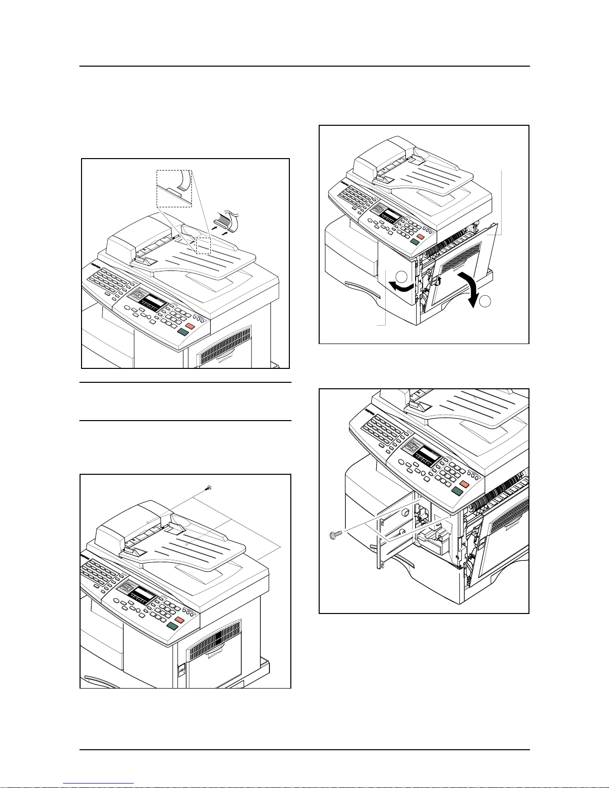
3-3 Scanner Ass'y
1. Before you remove the Scanner Ass'y, you
should remove:
- Rear Cover (see page 3-1)
2. Take out the Shield Main Upper.Unplug the one
connector and CCD cable.
Notice :
T o a void damage to the CCD cab le connector ensure that
you pull the cable out carefully. Pull in line with the connector not at an angle.
3. Remove the three screws, as shown below.
4. Open the Side Cover assembly first to open the
Front cover. In the other words, close the front
cover first to assembly it.
5. Remove two screws.
Side Cover Ass’y
Front Cover
1
2
Disassembly and Reassembly
Samsung Electronics
3-3
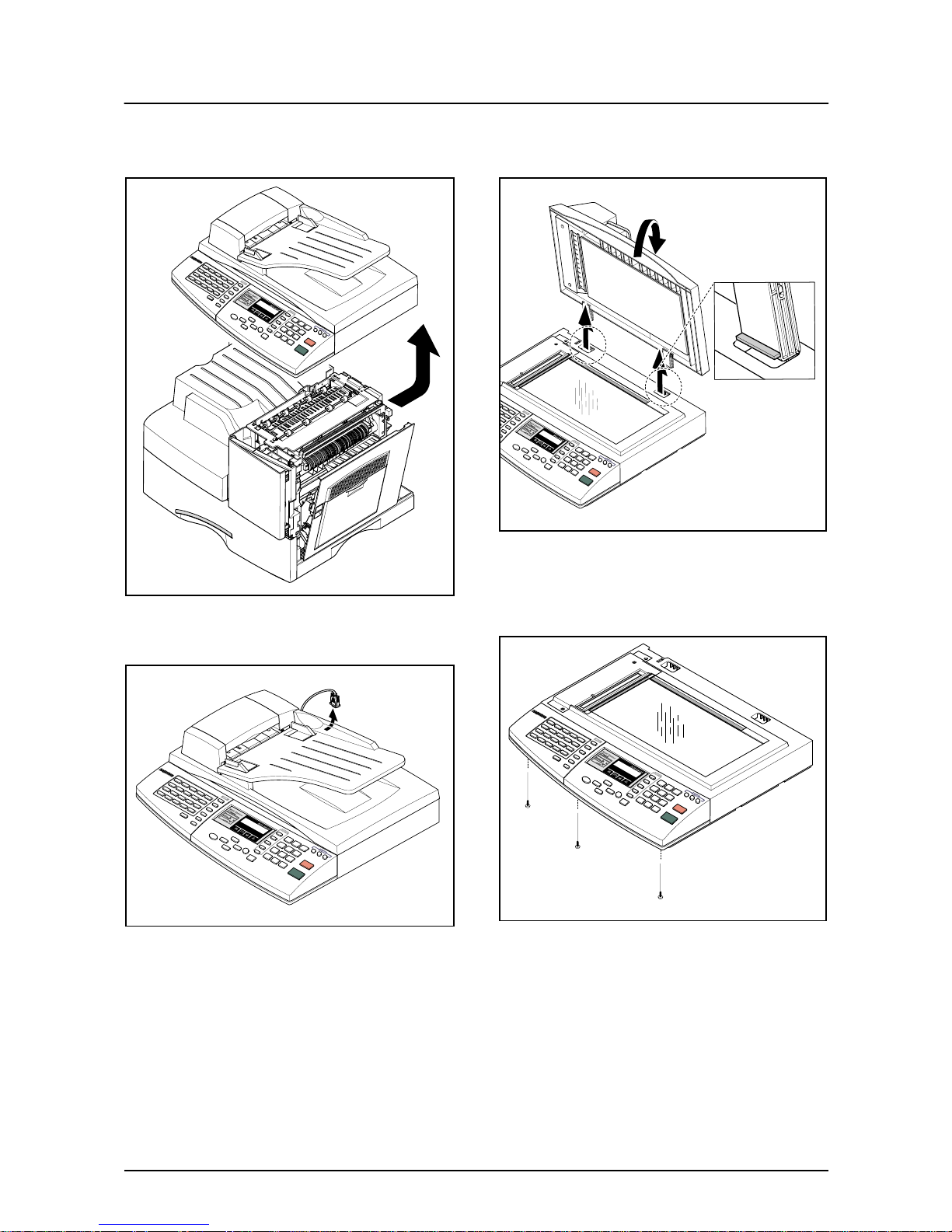
6. Pull up the Scanner Ass'y in the direction of
arrow.
7. Remove the connector from the Platen Ass'y.
8. Open the ADF Ass’y in the direction of arrow.
Pull the ADF Ass'y upward and remove it.
9. Remove the three screws securing the Platen
Ass'y.
Disassembly and Reassembly
3-4
Samsung Electronics
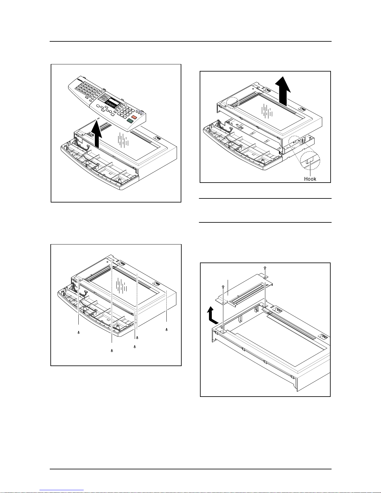
10. Pull the OPE Ass'y and unplug the one connector.
11. Remove the five screws securing the Platen Ass'y.
12. Unlatch the Scan Upper Ass'y securing the
glass and remove it.
Notice :
When dismantling the Scan Assy ensure your work area
is clean. Dirt or dust on the scan head can lead to a degradation in scanned image quality.
13. Remove the two scews and pull the Dummy
Upper Ass’y.
Dummy Upper Ass’y
Disassembly and Reassembly
Samsung Electronics
3-5
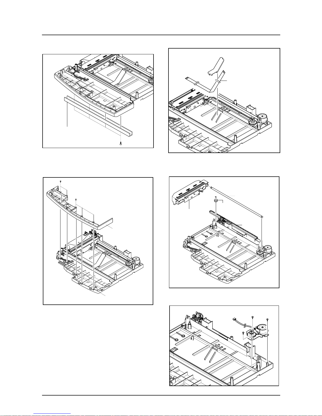
14. Remove the four screws and Channel Base
Frame.
15. Remove the five screws and Dummy ScanLower.
16. Remove the CCD cable.
17. Pull up the Shaft CCD and tak e out the Scanner
Module.
18. Remove three screws and take out the Motor
Bracket.
Channel Base Frame
Cover Scan Lower
Cover Dummy Lower
CCD Cable
Scanner Module
Shaft CCD
Belt
Pully
Disassembly and Reassembly
3-6
Samsung Electronics
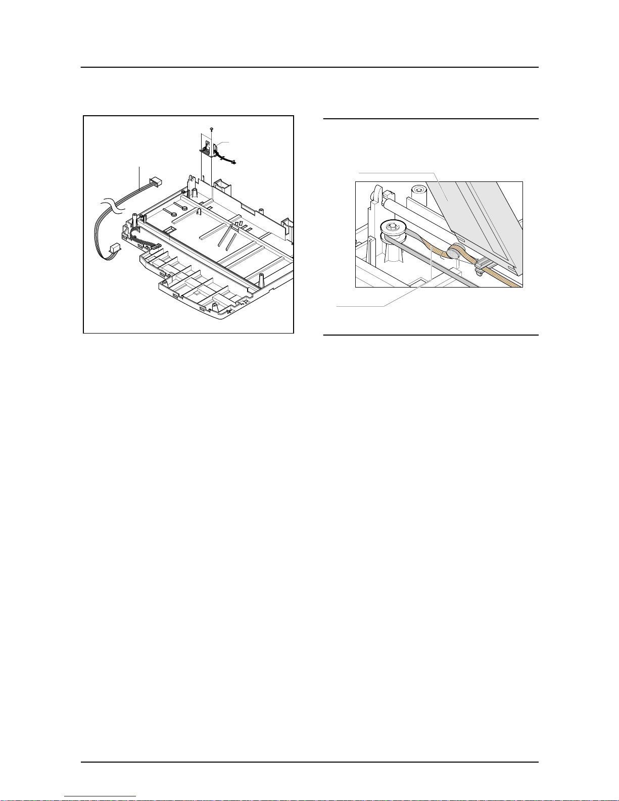
19. Remove the OPE Harness from the Platen
PBA. Remove two screws and take out the
Platen PBA.
Notice :
Take special care when reassembling the CCD Module
onto the Platen Ass'y. The CCD Module is located just to
the right side the Belt Tension Spring as shown below.
Platen PBA
OPE Harness
Scanner Module
Belt Tension Spring
Disassembly and Reassembly
Samsung Electronics
3-7
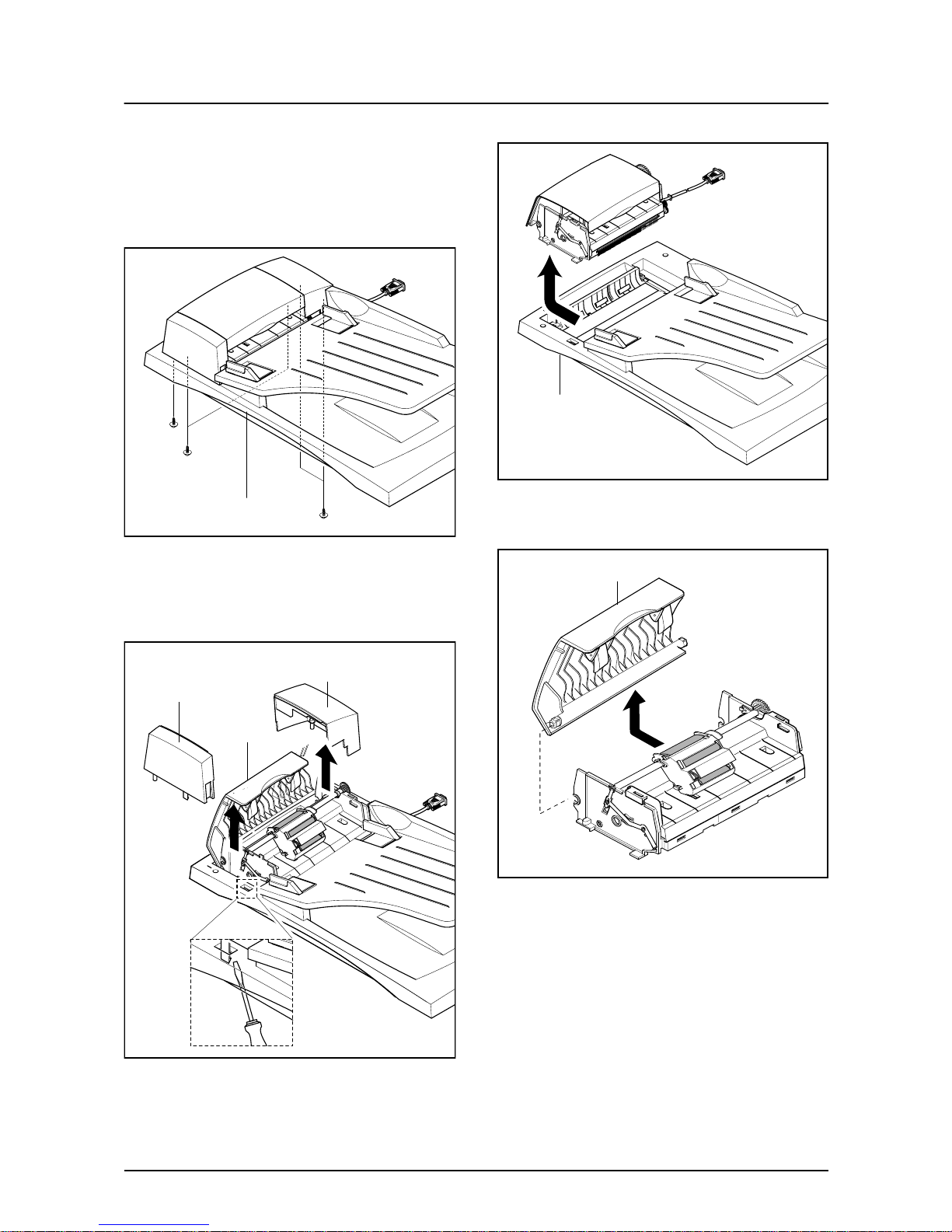
3-4 ADF Ass'y
1. Before you remove the ADF Ass'y, you should
remove:
- Rear Cover (see page 3-1)
- Scanner Ass'y (see page 3-2)
2. Remove the five screws from the Platen Cover.
3. Open the Co ver. Remov e Co ver Side R. Unlatch
the Side Cover L by pushing the catch hook ed to
the Platen Cover using a sharp tool and remove
Side Cover L.
4. Pull the ADF Ass'y upward and remove it.
5. Tack out he Open Cover.
Platen Cover Ass’y
Side Cover L
Cover Open
Side Cover R
Platen Cover Ass’y
Open Cover
Disassembly and Reassembly
3-8
Samsung Electronics
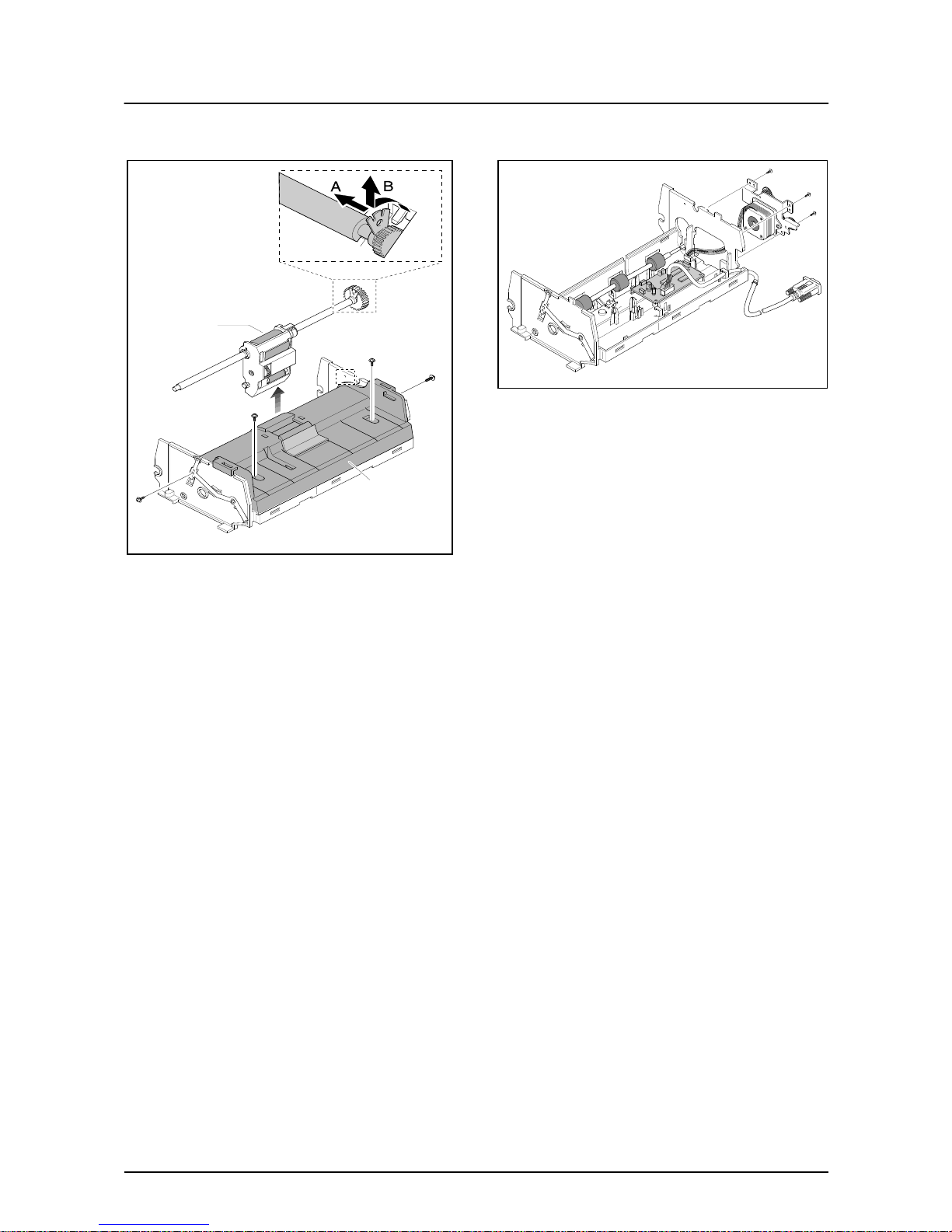
6. Take out the Pick-up Ass’y.
Remove the four screws and the ADF Upper.
7. Remove three screws and take out the ADF
Motor ass'y.
Pick-up Ass’y
ADF Upper

Disassembly and Reassembly
Samsung Electronics
3-9
3-5 OPE Ass'y
1. Before you remove the OPE Ass'y, you should
remove:
- Rear Cover (see page 3-1)
- Scanner Ass'y (see page 3-2)
2. Remove ten screws securing the OPE PBA and
the LCD Module from the OPE Cover.
3. Remove the contact rubbers from the unit.
4. Remove the key pad from the unit.
Caution
The above information is for the SCX-5315F model.
For the SCX-5115 model, the OPE Ass’y is slightly different, prats maked “a” are not fitted.
Disassembly and Reassembly
3-10
Samsung Electronics
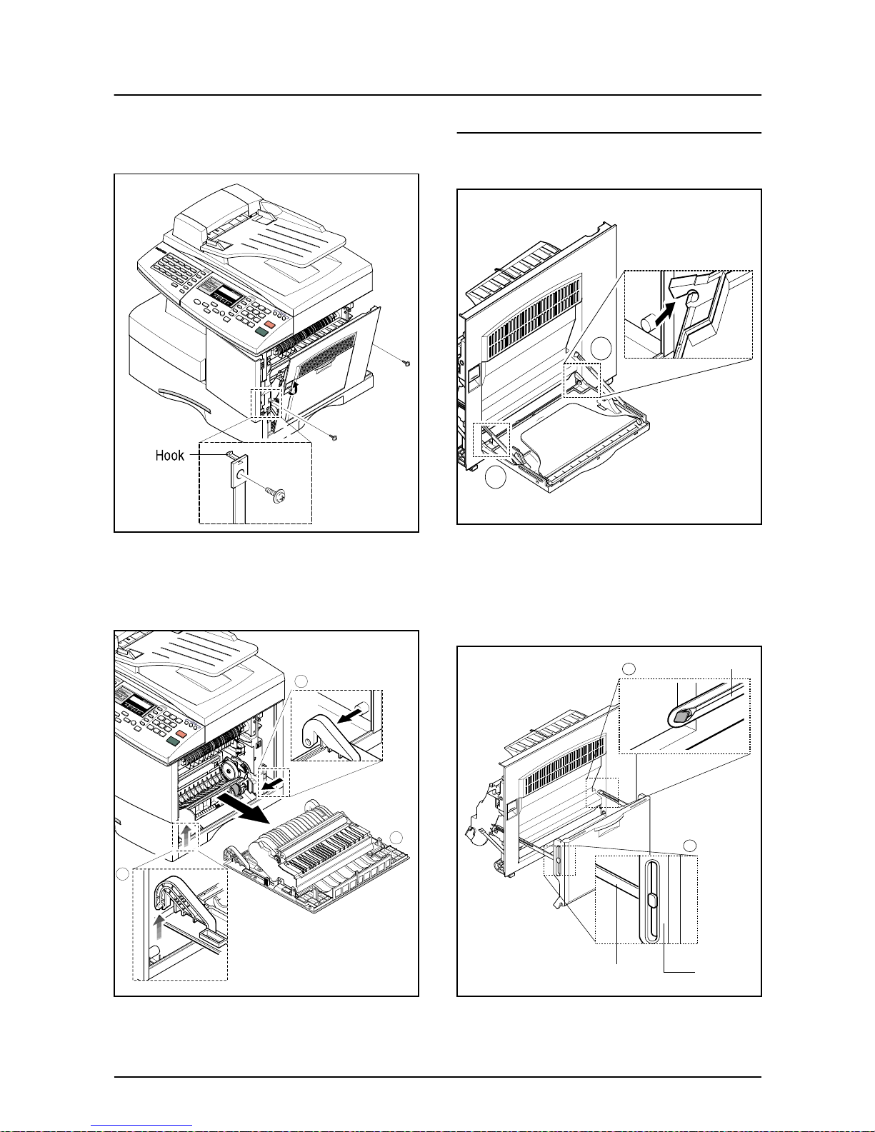
3-6 Side Cover Ass'y
1. Remove the two screws to release the Stopper(Main Frame side) securing the Side Cover
to the Main Frame.
2. Completely open the Side Cover door. The left
hand hinge (1) should be lifted to free it. Then
push the whole door assembly to the left to free
the right hand hinge (2).
* MP-Tray
1. To dismantle the MP tray release the lower
hinges (1).
2. As shown in (1) below align the door supports in
a horizontal position. This will allow the TrayCase to be removed from the Tray Links. To
remove the Tray-Links adjust the position of the
Tray Link to a 45?angle to align the slot in the
Tray Link
Tray-Case
MP Tray
1
2
1
1
1
2
3
Disassembly and Reassembly
Samsung Electronics
3-11
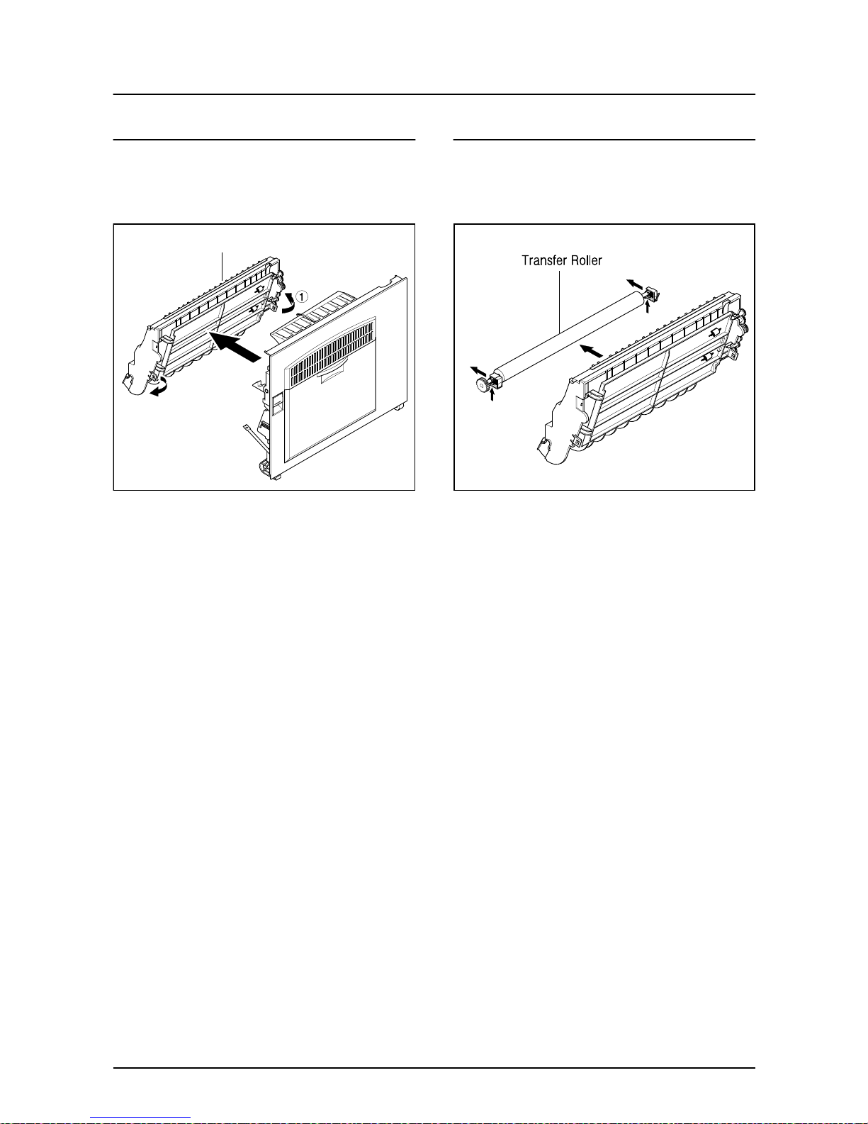
* Duplex Ass’y
1. To remove the Duplex Ass'y from the Side Door
Ass' locate the plastic clips, 2 on each side, and
release them.
Duplex Ass’y
* Transfer Roller Ass’y
1. Take out the Transfer Roller, as shown below.
Disassembly and Reassembly
3-12
Samsung Electronics
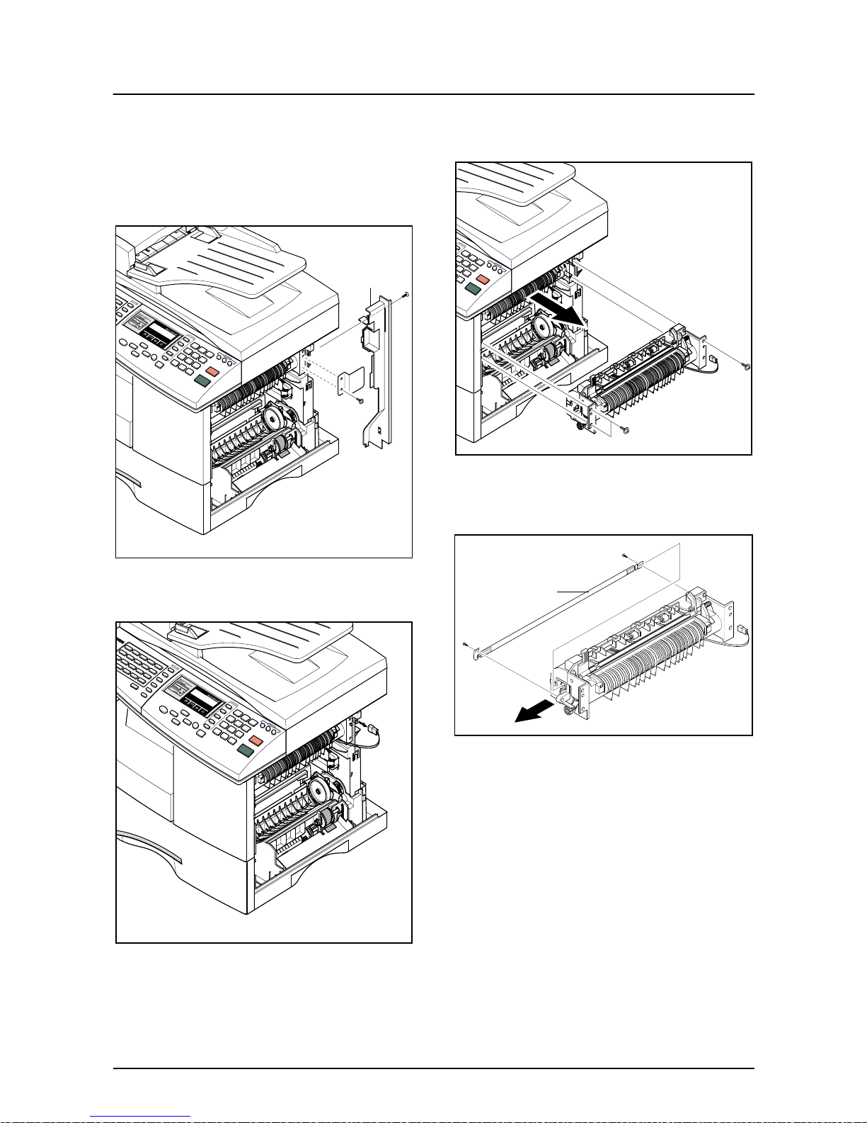
3-7 Fuser Ass'y
1. Before you remove the Fuser Ass'y, you should
ensure power is off and remove :
- Rear Cover Ass'y (see page 3-1)
- Side Cover Ass'y (see page 3-9)
2. Remove the two screws and take out the Connector Cover and the Cover Bracket.
3. Unplug the one connector.
4. Remo v e the three scre ws and tak e out the Fuser
Ass'y.
5. Remove the four screws and take out the Thermostat.
Cover Bracket
Halogen Lamp
Disassembly and Reassembly
Samsung Electronics
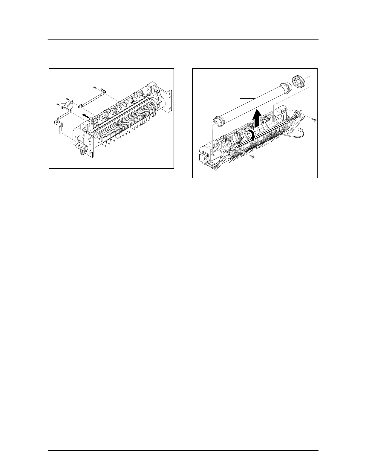
3-13
6. Remove the two screws and take out the Halogen Lamp.
7. Remove 2 screws and hinge open the Lower
Fuser Ass'y, remove the Heat Roller Ass'y from
the Upper Fuser Ass'y.
Thermostat
Heat Roller
Disassembly and Reassembly
3-14
Samsung Electronics
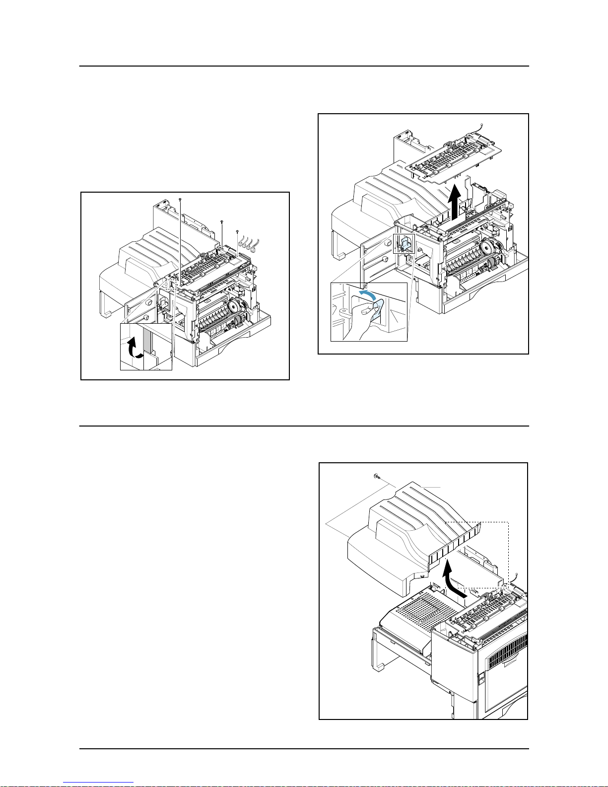
3-8 Exit Ass'y
1. Before you remove Exit Ass'y, you should
remove:
- Rear Cover (see page 3-1)
- Scanner Ass'y (see page 3-2)
2. Remo ve four screws, and then untie the harness
from the Exit Upper. Unplug f our connectors and
unlatch the Dummy Base Frame, as shown
below.
3. Mo ve the Exit Roller Release Le v er to the upright
position as shown in the diagram below and lift
the exit ass'y to remove it.
3-9 Cover Paper Exit Ass'y
1. Before you remove the Cover Paper Exit Ass'y,
you should remove:
- Rear Cover (see page 3-1)
- Scanner Ass'y (see page3-2)
2. Remo ve two screws and Cover Paper Exit Ass'y,
as shown below.
Cover Paper Exit Ass’y
Disassembly and Reassembly
Samsung Electronics
3-15
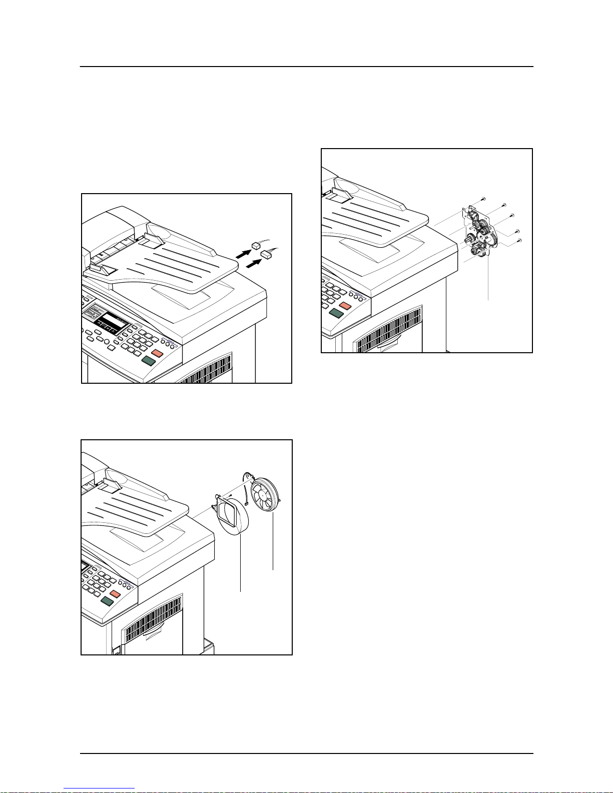
3-10 Drive Ass'y
1. Before you remove the Drive Ass'y, you should
remove:
- Rear Cover (see page 3-1)
- Shield Main Upper (see page 3-2)
2. Unplug the two connectors.
(Main Motor:9pin, Duplex Solenoid : 2pin)
3. Remo ve the one screw and take out the Fan and
Dust Fan.
4. Remove the five screws and take out the Drive
Ass'y.
Fan
Dust Fan
Drive Ass’y
Troubleshooting
Samsung Electronics 4-1
4. Maintenance & Troubleshooting
This chapter covers product maintenance, problem diagnosis and troubleshooting. It includes instructions for
diagnosing and resolving print quality problems.
This service manual covers both the SCX5315F and SCX5115 models. SCX5115 has printer, copier and
scanner functions. The SCX5315F has all of the features of the SCX5115 and in addition has Fax capabilities.
The manual contents are primarily written for the SCX5315F, where there are differences between the two
models this is highlighted.
4-1 Preventative Maintenance
The cycle period outlined below is a general guideline for maintenance.
The example list is for an average usage of 50 transmitted and received documents per day.
Environmental conditions and actual use will vary these factors.
The cycle period given below is for reference only.
COMPONENT REPLACEMENT CYCLE
ADF Rubber 20,000 Pages
ADF Roller 50,000 Pages
Pick-up Roller 75,000 Pages
Transfer Roller 75,000 Pages
Fuser 75,000 Pages
Toner Cartridge 6,000 Pages
Drum Cartridge 15,000 Pages

Troubleshooting
4-2
Samsung Electronics
4-2 Error Messages
Error Message Description Solution
RETRY REDIAL? The machine is waiting for the programmed inter-
val to automatically redial.
You can press START to immediately
redial, or STOP to cancel the redial
operation.
COMM. ERROR A problem with FAX communications has
occurred.
Try again.
DOCUMENT JAM Loaded document has Jammed in the scanner
document feeder
Clear the document Jam.
DOOR OPEN The side cover is not securely latched The side door and front door must be
closed in the correct order. Open both
doors. Close the front door first then
close the side door.
GROUP NOT AVAILABLE You have tried to select a group location where
only a single location number can be used, such
as when adding locations for a multi-dial operation.
Try again, check location for group.
LINE ERROR Your unit cannot connect with the remote
machine, or has lost contact because of a problem on the phone line.
Usually caused by a telephone line
problem. Try again. If failure persists,
wait an hour or so for the line to clear
then try again
LOAD DOCUMENT You have attempted to set up a sending opera-
tion with no document loaded.
Load a document and try again.
MEMORY FULL The memory has become full. Either delete unnecessary documents, or
retransmit after more memory becomes
available, or split the transmission into
more than one operation.
NO ANSWER The remote machine was not answered after all
the redial attempts.
Try again.
Make sure the remote machine is OK.
NO. NOT ASSIGNED The speed dial location you tried to use has no
number assigned to it.
Dial the number manually with the keypad, or assign the number.
NO PAPER
[ADD PAPER]
There is no paper in the paper cassette. Printing
stops until paper is loaded.
Re-load the paper cassette.
OVERHEAT The printer part has overheated. Your unit will automatically return to the
standby mode when it cools down to normal operating temperature. If failure persists, call service.
PAPER JAM 0
OPEN/CLOSE DOOR
Recording paper has jammed in paper feeding
area.
Recording paper is jammed in pick-up unit
Press STOP and clear the jam.
PAPER JAM 1/2
OPEN/CLOSE DOOR
Recording paper has jammed inside the unit.
Recording paper has jammed in paper exit unit.
Clear the jam.
TONER LOW Toner cartridge is almost empty, or toner particles
in the cartridge are unevenly distributed in the cartridge
Remove the toner cartridge and gently
rock it from side to side.
Try again. If problem persists replace the
cartridge.
TONER EMPTY Toner cartridge is now empty Replace the Toner Cartridge.

Troubleshooting
Samsung Electronics 4-3
DRUM WARNING A warning that the OPC drum has almost reached
the end of its life (14,000 Sides)
You have 1000 pages of print life left in
the OPC Drum. Continue to use, order
a new OPC drum.
REPLACE DRUM OPC drum is now life-expired
(15,000 sides)
Replace the OPC Drum Cartridge.
NO CARTRIDGE When the machine detects that the toner cartridge
has not been installed.
Install the Cartridge.
BYPASS JAM Paper feed problem from the BYPASS (Manual
feed) Tray.
Open the side Cover and clear the jam.
DUPLEX JAM Paper feed problem in the duplex return path Release Output Feed lever and check
output area clear. Also open side door
and check duplex unit is clear.
LINE BUSY The remote FAX didn’t answer Try again.
OPEN HEAT EROR No power to the Fuser lamp Check thermostat, thermistor, fuser lamp
and fuser connector and associated wiring. Also check the ‘Fuser On’ signal
from main PWA to Power Supply. Check
cable from Main PWA to Power Supply
Heating Error During operation, Temperature does not go up Check thermister contact point &
Heating Lamp.
Scanner Locked Scanner head does not move. Check transit lock, check scanner cables
are connected, check scanner home
sensor, scanner motor or drive belt.
Error Message Description Solution
Troubleshooting
4-4
Samsung Electronics
4-3 User Mode
The table below shows the settings and functions available in the User Mode. These are described in the user
Guide. The table is given here to indicate possible settings that the user may have changed.
4-3-1 SCX-5315F
✳❑n❄❏❊on✳❑n❄❏❊on
✳❑n❄❏❊on✳❑n❄❏❊on
✶❏❆m✶❏❆m
✶❏❆m✶❏❆m
✰on❏❆n❏✰on❏❆n❏
✰on❏❆n❏✰on❏❆n❏
SYSTEM DATA CASSETTE PAPER LETTER / A4 / LEGAL
BYPASS PAPER LETTER / A4 / LEGAL
MESSAGE CONF. ON / OFF / ERROR
AUTO JOURNAL ON / OFF
RECEIVE CODE 0-9
POWER SAVE ON / OFF
ECM MODE ON / OFF
RX REDUCTION ON / OFF
DISCARD SIZE 0-30mm
REDIAL INTERVAL 1-15
REDIALS 1-13
ANSWER ON RING 1-7
SEND FROM MEMORY ON / OFF
LOCAL ID ON / OFF
CLOCK MODE 12 / 24 HOUR
SYSTEM ID FAX / ID
DATE & TIME
SYSTEM SETUP PREFIX DIAL NO.
SECURE RECEIVE
RINGER VOLUME LOW / HIGH (10 STEPS)
ALARM SOUND ON / OFF
KEY SOUND ON / OFF
SPEAKER CONTROL COM / ON /OFF
SELECT LANGUAGE ENG/GER/FRE/ITA/SPA/POR/DUT
USB MODE FAST / SLOW
FAX DUPLEX OFF / LONG EDGE / SHORT EDGE
IMAGE QUALITY NORMAL / TEXT / IMAGE
SCAN SLEEP MODE HOME SET
MEMORY CLEAR SYSTEM ID
SYSTEM DATA
PHONE BOOK / MEMORY
TX-RX JOURNAL
DELA Y TX
MEMORY TX
PRIORITY TX
POLLING
ADD/CANCEL ADD / CANCEL
GROUP DIAL

Troubleshooting
Samsung Electronics 4-5
4-3-2 SCX-5115
4-4 T ech Mode
4-4-1 How to Enter Service Mode
In service mode (tech) mode, the technician can check the machine and perform various tests to isolate the
cause of a malfunction.
To enter the Tech mode, press MENU, #, 1, 9, 3, 4 in sequence, and the LCD briefly displays ‘T’ or ‘TECH’,
the machine has entered service (tech) mode.
While in Tech mode, the machine still performs all normal operations.
To return to normal user mode, press MENU, #, 1, 9, 3, 4 in sequence again, or turn the power off, then on
by unplugging and plugging the power cord.
Options changed while in service mode remain in effect until they are changed again or until you clear the
machine’s memory.
MAINTENANCE CLEAN DRUM
NEW DRUM
NOTIFY TONER LOW ON / OFF
TX CONFIRM
SCHEDULE JOB
PHONE BOOK
SYSTEM LIST
TX JOURNAL
RX JOURNAL
HELP LIST HELP LIST
✳❑n❄❏❊on✳❑n❄❏❊on
✳❑n❄❏❊on✳❑n❄❏❊on
✶❏❆m✶❏❆m
✶❏❆m✶❏❆m
✰on❏❆n❏✰on❏❆n❏
✰on❏❆n❏✰on❏❆n❏
SYSTEM DATA CASSETTE PAPER LETTER / A4 / LEGAL
BYPASS PAPER LETTER / A4 / LEGAL
POWER SAVE ON / OFF
SELECT LANGUAGE ENG/GER/FRE/ITA/SPA/POR/DUT
USB MODE FAST / SLOW
HELP LIST HELP LIST PRINTOUT
MAINTENANCE CLEAN DRUM
NEW DRUM
REPORTS SYSTEM DATA
HELP LIST HELP LIST
✳❑n❄❏❊on✳❑n❄❏❊on
✳❑n❄❏❊on✳❑n❄❏❊on
✶❏❆m✶❏❆m
✶❏❆m✶❏❆m
✰on❏❆n❏✰on❏❆n❏
✰on❏❆n❏✰on❏❆n❏
Troubleshooting
4-6
Samsung Electronics
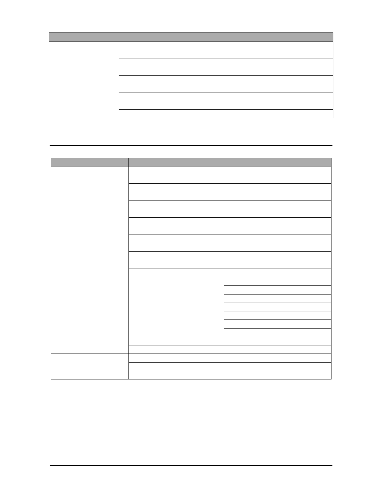
4-4-2 Setting-up System in Tech Mode
4-4-2-1 SCX-5315F(SETUP : #, 1, 9, 3, 4)
✳❑n❄❏❊on✳❑n❄❏❊on
✳❑n❄❏❊on✳❑n❄❏❊on
✶❏❆m✶❏❆m
✶❏❆m✶❏❆m
✰on❏❆n❏✰on❏❆n❏
✰on❏❆n❏✰on❏❆n❏
SYSTEM DATA DIAL MODE TONE / PULSE
MODEM SPEED
ERROR RATE 5% /10%
SET TX LEVEL 09-15
SILENCE TIME 12 / NU / OFF
SYSTEM ID The same as User Mode
DATE & TIME The same as User Mode
SYSTEM SETUP The same as User Mode
MEMORY CLEAR CLEAR ALL MEMORY
DELAY TX The same as User Mode
MEMORY TX The same as User Mode
PRIORITY TX The same as User Mode
POLLING The same as User Mode
ADD/CANCEL The same as User Mode
GROUP DIAL The same as User Mode
MAINTENANCE CLEAN DRUM
NEW DRUM
NOTIFY TONER LOW ON / OFF
SWITCH TEST
MODEM TEST
SRAM TEST
DRAM TEST
ROM TEST FLASH / ENGINE
PATTERN TEST PATTERN1-7, QAPATTERN1-4, ALL"1-7 , ALL"
CLEAR COUNT PASSWORD
(1934)
CRU PRINTS COUNT
FLT SCAN COUNT
ADF SCAN COUNT
USED DRUM COUNT
USED TONER COUNT
TOTAL PAGE COUNT
ANSWER ON CNG 1-4
ADJUST SHADING
FLASH UPGRADE LOCAL
REMOTE : USER PROGRAM ,
EMULATION ,BOOT PROGRAM
PROGRAM DIAL
TX CONFIRM The same as User Mode
SCHEDULE JOB The same as User Mode
PHONE BOOK The same as User Mode
SYSTEM LIST USER MODE
TX JOURNAL The same as User Mode
RX JOURNAL The same as User Mode
Troubleshooting
Samsung Electronics 4-7
4-4-2-2 SCX-5115(SETUP : #, 1, 9, 3, 4)
REPORTS MSG. CONFIRM
SCHEDULE JOB
PHONE BOOK
SYSTEM DATA
TRANSMISSION
RECEPTION
HELP LIST
PROTOCOL
ERROR CODE
✳❑n❄❏❊on✳❑n❄❏❊on
✳❑n❄❏❊on✳❑n❄❏❊on
✶❏❆m✶❏❆m
✶❏❆m✶❏❆m
✰on❏❆n❏✰on❏❆n❏
✰on❏❆n❏✰on❏❆n❏
SYSTEM DATA CASSETTE PAPER LETTER / A4 / LEGAL
BYPASS PAPER LETTER / A4 / LEGAL
POWER SAVE ON / OFF
SELECT LANGUAGE ENG/GER/FRE/ITA/SPA/POR/DUT
USB MODE FAST / SLOW
MAINTENANCE CLEAN DRUM
MODEM TEST
NEW DRUM
SWITCH TEST
SRAM TEST
DRAM TEST
ROM TEST FLASH / ENGINE
PATTERN TEST PATTERN1-7, QAPATTERN1-4 , ALL
CLEAR COUNT PASSWORD
CRU PRINTS COUNT
FLT SCAN COUNT
ADF SCAN COUNT
USED DRUM COUNT
USED TONER COUNT
TOTAL PAGE COUNT
ADJUST SHADING
FLASH UPGRADE
REPORTS SYSTEM DATA
HELP LIST HELP LIST
ERROR CODE
✳❑n❄❏❊on✳❑n❄❏❊on
✳❑n❄❏❊on✳❑n❄❏❊on
✶❏❆m✶❏❆m
✶❏❆m✶❏❆m
✰on❏❆n❏✰on❏❆n❏
✰on❏❆n❏✰on❏❆n❏

Troubleshooting
4-8
Samsung Electronics
4-4-3 SYSTEM DATA
DIALING MODE
Select the dialing mode according to the user's line status.
TONE: Electrical type of dial
PULSE: Mechanical type of dial
SILENCE TIME
In ANS/FAX mode, after a call is picked up by the answering machine, the machine monitors the line. If a
period of silence is detected on the line at any time, the call will be treated as a fax message and the machine
begins receiving.
Silence detection time is selectable between limited (about 12 seconds) and unlimited time.
When '12 sec' is selected, the machine switches to receiving mode as soon as it detects a period of silence.
When 'unlimited'is selected, the machine waits until the answering operation is concluded even though a
period of silence is detected. After the answering operation is concluded, the machine switches to receiving
mode.
SEND FAX LEVEL
You can set the level of the transmission signal. Typically, the Tx level should be under -12 dBm.
Caution: The Send Fax Level is set at the best condition in the shipment from factory. Never change
settings arbitrarily.
ERROR RATE
Tou can set the Error Rate between 5% and 10%. During operation the set monitors the rror rate.
When the rror rate approaches the preset value the machine automatically steps down the baude to 2400bps
to ensure that the selected error rate is not exceeded.
MODEM SPEED
You can set the maximum modem speed. It is better left set 33.6Kbps (the default setting ).
During call setup the baud rate is automatically adjusted to suite the slowest device. Only adjust this where
the local line conditions are extremely poor.
4-4-4 MEMORY CLEAR
CLEAR ALL MEMORY
This function resets the system to its original factory settings. All settings entered in User Mode and Tech
Mode are reset. This includes any User Phone Book entries, jobs stored in memory or received documents
that have not been printed. If possible use the Control Panel software to download customer settings and
phone book settings before carrying out a full reset.
When diagnosing or testing a faulty unit this function is often useful. Be aware that all error reports are also
cleared.
< Method >
1. Select the [MEMORY CLEAR] in TECH MODE.
2. Push the ENTER button.
3. Select your country.
4. Push the ENTER button and all memory will be cleared.
NOTICE : Always perform a memory clear after replacing the main board or updating the firmware. Oth-
erwise, the system may not operate properly.
Troubleshooting
Samsung Electronics 4-9
4-4-5 MAINTENANCE
CLEAN DRUM
Use this feature to remove toner particles remaining in the OPC drum unit.
Use this feature when print quality falls or when marks or specks appear on the printout.
You should perform this feature several times until a clean printout appears.
The machine automatically pulls in a sheet of paper and prints out. Excess toner particles on the OPC drum
surface are fixed to the paper.
FLASH UPGRADE
This function is used to update the system Firmware. There are 2 methods Local and Remote.
More information can be found in the firmware upgrade section.
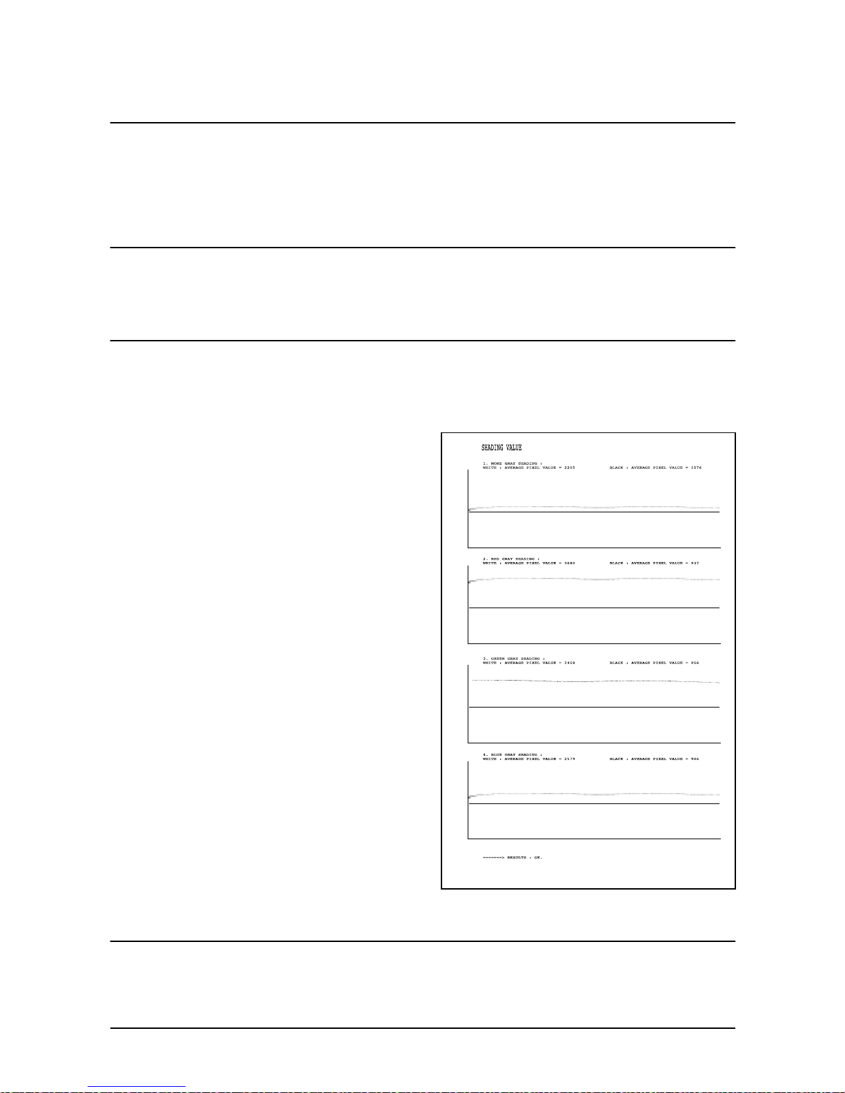
ADJUST SHADING
This option is used to test and check the functionality of the CCD (Charge Coupled Device). Use this when
poor quality scanning or copying is reported.
< Method >
1. Select the [ADJUST SHADING] in TECH MODE.
2. Push the SET UP button. The unit scans
a “white image” using the ‘white bar’
3. After the scan, CCD SHADING PROFILE similar to that
shown will be printed out.
4. If the printed image is different to the image, if the lines
are significantly lower or higher, or if there are high or low
spots in the chart then the CCD is defective.
NOTICE : When you test the CCD, make
sure that the cover is closed.”
ANSWER ON CNG
The function is to control the CNG T ONE recognition times f or entering receiving mode from the A UTO MODE
or ANS/FAX MODE.
 Loading...