

Samsung SCX-5312 Service manual
DIGITAL LASER MFP
SCX-5312F
SCX-5112
SERVICE
DIGITAL LASER MFP
MANUAL
CONTENTS
1. Precautions
2. Specifications
3. Disassembly
4. T roubleshooting
5. Exploded Views and Parts List
6. Block Diagram
7. Connection Diagram


Precautions
1. Precautions
Follow these safety, ESD, and servicing precautions to prevent personal injury and equipment damage.
1-1 Safety Precautions
1. Be sure that all built-in protective devices are in
place. Restore any missing protective shields.
2. Make sure there are no cabinet openings
through which people-particularly children- might
insert fingers or objects and contact dangerous
voltages.
3. When re-installing chassis and assemblies, be
sure to restore all protective devices, including
control knobs and compartment covers.
4. Design Alteration Warning:Never alter or add to
the mechanical or electrical design of this equipment, such as auxiliary connectors, etc. Such
alterations and modifications will void the manufacturer’s warranty.
5. Components, parts, and wiring that appear to
have overheated or are otherwise damaged
should be replaced with parts which meet the
original specifications. Always determine the
cause of damage or overheating, and correct any
potential hazards.
6. Observe the original lead dress, especially near
sharp edges, AC, and high voltage power supplies. Always inspect for pinched, out-of-place,
or frayed wiring. Do not change the spacing
between components and the printed circuit
board.
7. Product Safety Notice:Some electrical and
mechanical parts have special safety-related
characteristics which might not be obvious from
visual inspection. These safety features and the
protection they provide could be lost if a replacement component differs from the original. This
holds true, even though the replacement may be
rated for higher voltage, wattage, etc.
8. Components critical for safety are indicated in
the parts list with symbols .
Use only replacement components that have the
same ratings, especially for flame resistance and
dielectric specifications. A replacement part that
does not have the same safety characteristics as
the original may create shock, fire, or other
safety hazards.
1-2 Precautions on Disassembly and Reassembly
Very careful precautions should be taken when
replacing parts. Before replacing, please check
cables because you cannot put the cables that you
removed for replacing parts into the proper place if
you would not make sure of where they were connected and in which condition.
Please do the following before disassembling for a
repair or replacement of parts.
1. Pull out paper cassette, printer cartridge
installed. Especially careful not to be scratched
by the surface of developer or not to expose
them to light.
2. Turn the power switch off.
3. Take out the power plug, printer cable from the
printer.
4. Use only the same type of part as original when
replacing parts.
5. Do not force to open or fasten plastic material
components.
6. Be careful that small parts such as screws
should not get in the printer.
7. When disassembling, assembling, also observe
small components are located in place.
8. If you uncover and turn the machine over to
replace some parts, toner or paper particles may
contaminate the LSU window. Protect the LSU
window with clean paper.
Releasing Plastic Latches
Many of parts are held in
place with plastic latches.
The latches break easily :
release them carefully.
To remove such parts,
press the hook end of the
latch away from the part to
which it is latched.
Samsung Electronics
1-1

Precautions
1-3 ESD Precautions
1. Certain semiconductor devices can be easily
damaged by static electricity. Such components
are commonly called “Electrostatically Sensitive
(ES) Devices”, or ESDs. Examples of typical
ESDs are: integrated circuits, some field effect
transistors, and semiconductor “chip” components.
The techniques outlined below should be followed to help reduce the incidence of component
damage caused by static electricity.
CAUTION : Be sure no po wer is applied to the chassis
or circuit, and observe all other safety precautions.
2. Immediately before handling a semiconductor
component or semiconductor-equipped assembly, drain off any electrostatic charge on your
body by touching a known earth ground. Alternatively, employ a commercially available wrist
strap device, which should be removed for your
personal safety reasons prior to applying power
to the unit under test.
3. After removing an electrical assembly equipped
with ESDs, place the assembly on a conductive
surface, such as aluminum or copper foil, or conductive foam, to prevent electrostatic charge
buildup in the vicinity of the assembly.
4. Use only a grounded tip soldering iron to solder
or desolder ESDs.
Use only an “anti-static” solder removal device.
Some solder removal devices not classified as
“anti-static” can generate electrical charges sufficient to damage ESDs.
5. Do not use Freon-propelled chemicals. When
sprayed, these can generate electrical charges
sufficient to damage ESDs.
6. Do not remove a replacement ESD from its protective packaging until immediately bef ore installing it. Most replacement ESDs are packaged
with all leads shorted together by conductive
foam, aluminum f oil, or a comparable conductive
material.
7. Immediately before removing the protective
shorting material from the leads of a replacement ESD, touch the protective material to the
chassis or circuit assembly into which the device
will be installed.
8. Maintain continuous electrical contact between
the ESD and the assembly into which it will be
installed, until completely plugged or soldered
into the circuit.
9. Minimize bodily motions when handling unpackaged replacement ESDs. Normal motions, such
as the brushing together of clothing fabric and
lifting one’s f oot from a carpeted floor , can generate static electricity sufficient to damage an ESD.
1-4 Super Capacitor or Lithium Battery Precautions
1. Exercise caution when replacing a super capacitor or Lithium battery. There could be a danger of
explosion and subsequent operator injury and/or
equipment damage if incorrectly installed.
2. Be sure to replace the battery with the same or
equivalent type recommended by the manufacturer.
3. Super capacitor or Lithium batteries contain toxic
substances and should not be opened, crushed,
or burned for disposal.
4. Dispose of used batteries according to the manufacture’s instructions.
Samsung Electronics1-2
Precautions
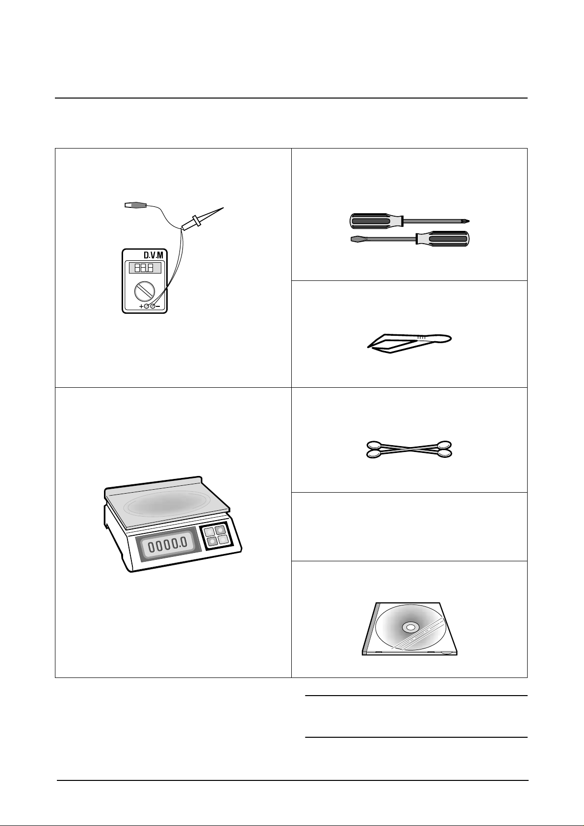
1-5 Tools for Troubleshooting
The following tools are recommended for safe and smooth troubleshooting described in this service manual.
1
DVM(Digital Volt Meter)
Standard: Indicates more than 3 digits.
3
Driver
Standard: "-" type, "+" type (M3 long, M3 short, M2
long, M2 short).
4
Pinset
Standard: For general home use, small type.
2
Electronic Scale
Standard: Equipment to check the weight of consumables(toner cartridge) supplied by Samsung Electronics. (The gram unit can be measured.)
5
Cotton Swab
Standard: For general home use, for medical service.
6
Cleaning Equipments a IPA(Isopropyl
Alcohol)dry cloth or a soft stuff neutral
detergent.
7
Software(Driver) installation CD ROM
Samsung Electronics
Note : Mind your hands not to be touched when you
disassemble and reassemble PBA ASS'Y,
such as the main board, SMPS, HVPS.
1-3
Specification
2. Specification
Specifications are correct at the time of printing. Product specifications are subject to change without notice.
See below for product specifications.
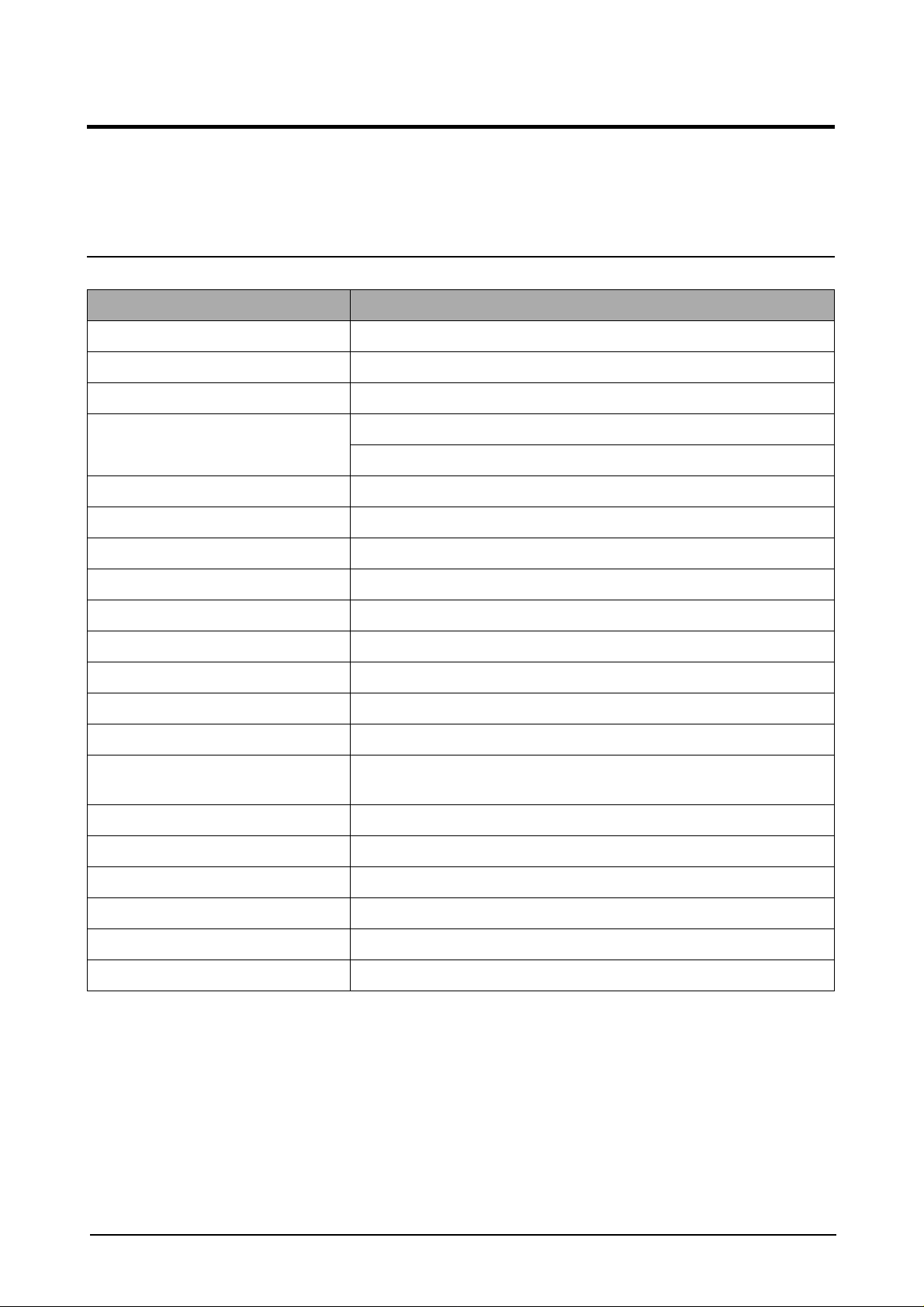
2-1 General Specifications
Item Description
Type of Unit Desktop
Operation System Win95/98/ME/ NT /2000/XP
Duplex Printing Yes(Default)
Interface IEEE1284(Nibbel/ECP)
USB(without HUB mode)
CPU 66 MHz(KS32C61200)
Emulation PCL6
Warming up Time 41 Sec (Stand-By), 25˚C
Absolute Storage Condition Temperature : -20°C ~ 40°C, Humidity : 10% RH ~ 95% RH
Operating Condition Temperature : 10˚C ~ 32˚C, Humidity : 20% RH ~ 80 % RH
Recommended Operating Condition Temperature : 16°C ~ 30°C, Humidity : 30% RH ~ 70% RH
Dimension(W X D X H) 560 X 433 X 459 mm
Weight About 22.5 Kg(with CRU)
Acoustic Noise Less than 56/47 dB(Copy/Printing mode)
Power Rating AC 100VAC ~ 127VAC ± 15 %, 50/60Hz ± 3Hz
AC 220VAC ~ 240VAC ± 15 % , 50/60Hz ± 3Hz
Power Consumption Avg. 320Wh ( No load Condition)
Power Save Consumption Avg. 35Wh
Recommended System Requirement Pentium II 233 Mhz, 64 MB RAM, 120MB(Hard Disk)
Minimum System Requirement Pentium II 400Mhz, 128 MB RAM, 220MB(Hard Disk)
LCD 16 characters X 2 lines
Memory 4 Mbyte for flash Memory , 16 Mbyte for DRAM
Samsung Electronics
2-1

Specification
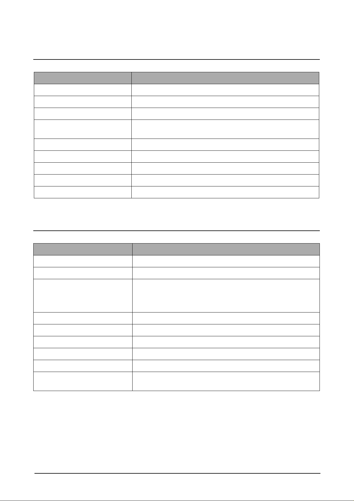
2-2 Printer Specifications
Item Description
Printing Method Laser Scanning Unit + Electro Photography
Speed Single Side : 12 PPM
(Letter Size, 5% Character Pattern)
Duplex : 7.5 IPM(Images/Min) (Letter Size, 5% Character Pattern)
Source of Light LSU(Laser Scanning Unit)
Duplex Printing Yes(Default)
Resolution(Horizontal X Vertical) True 600 X600 DPI , 1200 DPI Class
Feed Method Cassette Type , By Pass Tray,
ADF(Automatic Document Feeder)
Feed Direction FISO(Front-In Side-Out)
Paper Capacity(Input) Cassette : 550 Sheets
By Pass Tray : 100 Sheets(based on 75g/ß
Paper Capacity(Output) Face Down : 250 Sheets
Effective Print Width 203 ± 1mm (8 inch)
≥ , 20lb)
2-3 Facsimile Specification(SCX-5312F Only)
Item Description
Standard Recommendation ITU-T Group3(ITU : International Telecommunications Union)
Application Circuit PSTN or behind PABX
(PSTN : Public Switched Telephone Network.
PABX : Private Automatic Branch Exchange)
Data coding(Compression) MH/MR/MMR/JPEG(Transmission)
Modem speed 33600 /14400/12000/9600/7200/4800/2400 bps
Transmission Speed Approximately 3 sec(33,600 bps)
Effective Scanning Width 8.2 inches(208 mm)
Halftone 256 Levels
Paper Capacity(Input) ADF(Automatic Document Feeder) : 30Sheets(75g/ß
FAX Mode Standard /Fine/Super Fine/Halftone
Memory 4MB
Samsung Electronics2-2
≥ )
2-4 Scanner Specification
Item Description
Type Flatbed(with ADF)
Speed Mono : 1.25 msec/line, Color : 5 msec/line
Device Color CCD(Charge Coupled Device) Module
Interface IEEE1284(ECP Support)
USB(without HUB Mode)
Compatibility TWAIN Standard , WIA
Optical Resolution(H X V) 600 X 600 dpi
Interpolation Resolution Max. 4800 dpi
Halftone 256 Levels
Specification
Effective Scan width 8.2 inches(208 mm)
2-5 Copy Specification
Item Description
Mode B/W
Quality Text/Photo/Mixed
Mono Copy Speed
Optical Resolution (H x V) 600 X 600 dpi
Multi Copy 99 pages
Maximum Original Size Legal
Maximum Page Size Legal
(1)
Platen(SDMP) : 12 cpm
ADF (SDMP) : 12 cpm
ADF (MDSP) : Text/mixed : Approx. 7 cpm
: Photo : Approx. 3 cpm
Paper Type Selection Plain , Legal , Cardstock , Transparency
Zoom Range Platen : 25 ~ 400%(1% Step)
ADF : 25~100 %(1% Step)
NOTE :
(1) Speed claims based on the test chart : Letter size.
SDMP : Single Document Multiple Printout
MDSP : Multiple Document Single Printout
Samsung Electronics
2-3
Specification
2-6 Telephone Specification(SCX-5312F Only)
Item Description
1Touch Dial 40EA(1~20 , shift key + 21~40)
Speed Dial 80EA
Tone/Pulse Tone only user modeTone/Pulse selectable in tech mode.
2-7 Consumables
Item Description
Type Separate type
(Toner Cartridge / Drum Cartridge)
Life Toner Cartridge 6,000 sheets
( 5% coverage pattern, simplex normal mode )
Drum Cartridge 15,000 sheets
(simplex normal mode )
Samsung Electronics2-4
Disassembly and Reassembly
3. Disassembly and Reassembly
3-1 General Precautions on Disassembly
When you disassemble and reassemble components, you must use extreme caution.
The close proximity of cables to moving parts makes proper routing a must. If components are removed, any
cables disturbed by the procedure must be restored as close as possible to their original positions. Before
removing any component from the machine, note the cable routing that will be affected.
Whenever servicing the machine, you must perform as follows:
1. Check to verify that documents are not stored in memory.
2. Unplug the power cord.
3. Use a flat and clean surface.
4. Replace only with authorized components.
5. Do not force to remove or planten plastic-material components.
6. Make sure all components are in their proper position.
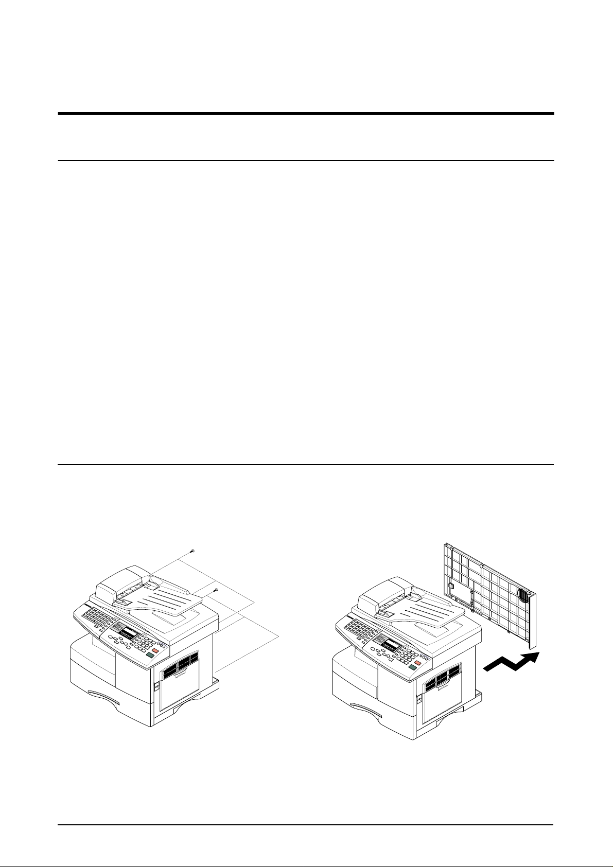
3-2 Rear Cover
1. Remo ve the six screws securing the Rear Cover . 2. Separate the rear cover from the base frame
and Scanner Ass'y.
Samsung Electronics
3-1

Disassembly and Reassembly
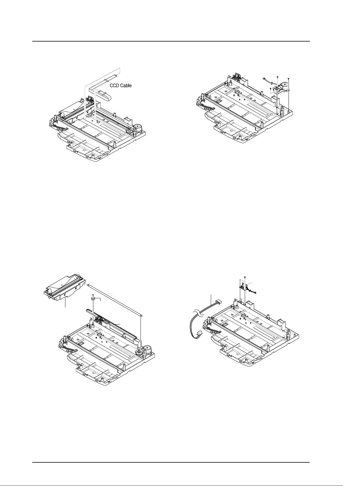
3-3 Scanner Ass'y
1. Before you remove the Scanner Ass'y, you
should remove:
- Rear Cover (see page 3-1)
2. Remove the six screws and take out the Shield
Main Upper.Unplug the one connector and CCD
cable.
Shield Main Upper
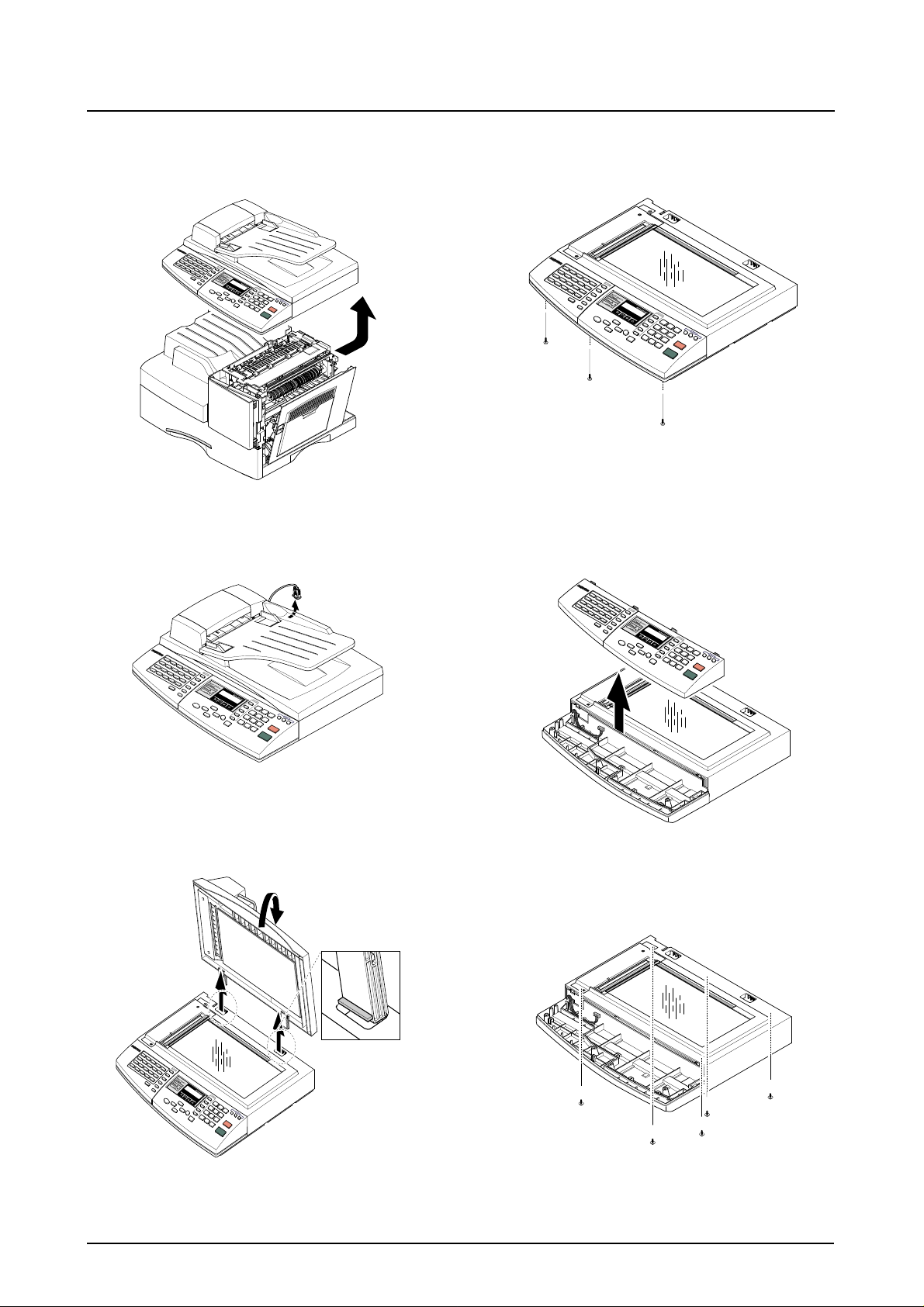
4. Open the Side Cover assembly first to open the
Front cover. In the other words, close the front
cover first to assembly it.
.
Side Cover Ass’y
2
1
Front Cover
Notice :
You should connector remove the CCD cable vertically to
avoid the CCD cable pin damage.
3. Remove the three screws, as shown below.
5. Remove two screws.
3-2
Samsung Electronics
Disassembly and Reassembly
6. Pull up the Scanner Ass'y in the direction of
arrow.
7. Remove the connector from the Platen Ass'y.
9. Remove the three screws securing the Platen
Ass'y.
10. Pull the OPE Ass'y and unplug the one connector.
8. Open the ADF Ass’y in the direction of arrow.
Pull the ADF Ass'y upward and remove it.
Samsung Electronics
11. Remove the five screws securing the Platen Ass'y.
3-3
Disassembly and Reassembly
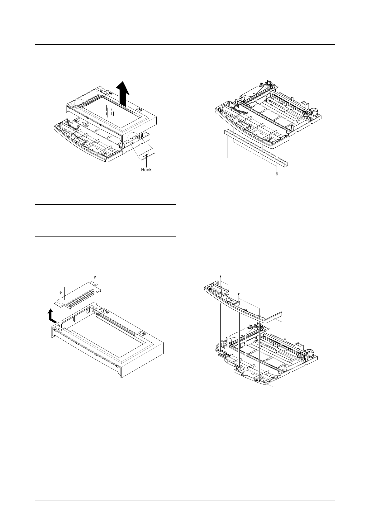
12. Unlatch the Scan Upper Ass'y securing the
glass and remove it.
Notice :
When foreign material enters into the Scan Assy, it may
cause problems in product performance and deteriorate
scan image. Therefore, you should always dismantle or
assemble it at a clean place.
14. Remove the four screws and Channel Base
Frame.
Channel Base Frame
13. Remove the two scews and pull the Dummy
Upper Ass’y.
Dummy Upper Ass’y
15. Remove the five screws and Dummy ScanLower.
Cover Dummy Lower
Cover Scan Lower
3-4
Samsung Electronics
Disassembly and Reassembly
16. Remove the CCD cable.
18. Remove three screws and take out the Motor
Bracket.
17. Pull up the Shaft CCD and tak e out the Scanner
Module.
Shaft CCD
Pully
Scanner Module
Belt
19. Remove the OPE Harness from the Platen
PBA. Remove two screws and take out the
Platen PBA.
Platen PBA
OPE Harness
Samsung Electronics
3-5
Disassembly and Reassembly
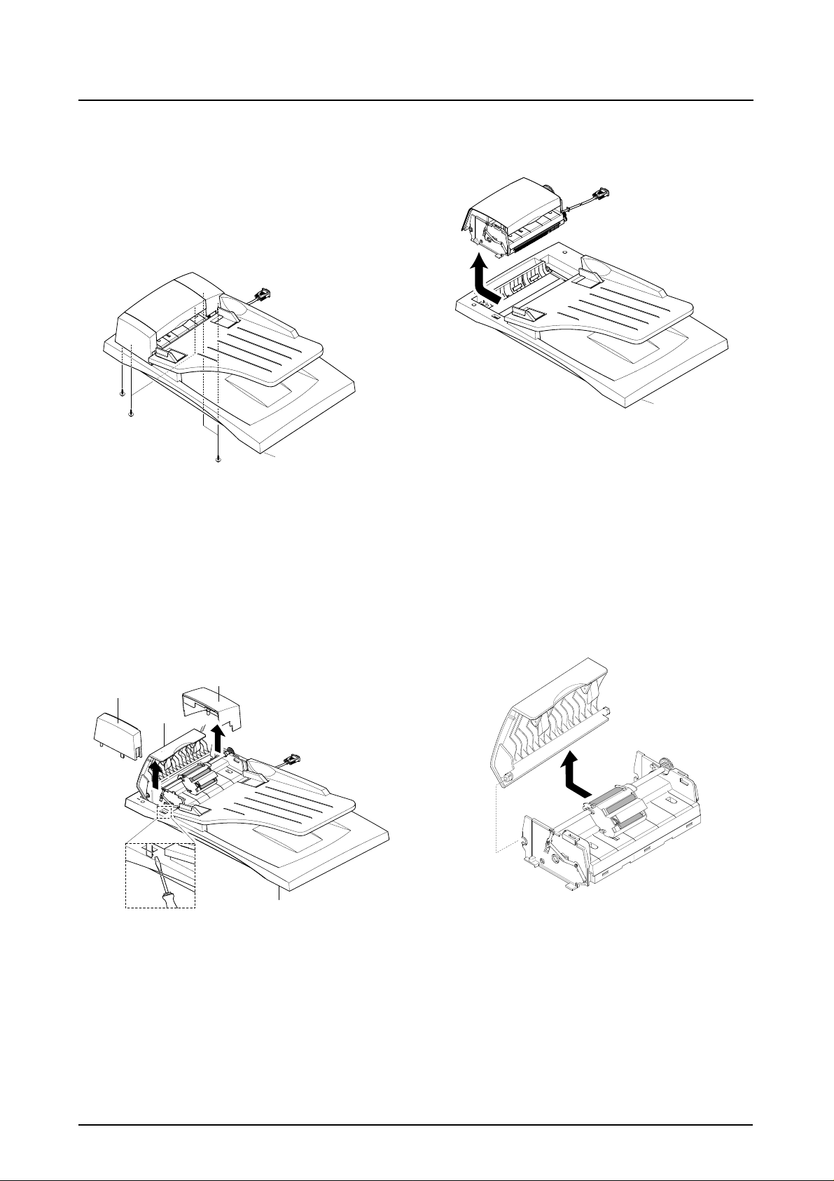
3-4 ADF Ass'y
1. Before you remove the ADF Ass'y, you should
remove:
- Rear Cover (see page 3-1)
- Scanner Ass'y (see page 3-2)
2. Remove the five screws from the Platen Cover.
Platen Cover Ass’y
4. Pull the ADF Ass'y upward and remove it.
Platen Cover Ass’y
3. Open the Cover open and pull the Cover Side L
and Cover Side R and unlatch the Side Cover L
by pushing the part hooked the Platen Cover
using a sharp tool.
Side Cover R
Side Cover L
Cover Open
Platen Cover Ass’y
5. Tack out he Open Cover.
3-6
Samsung Electronics
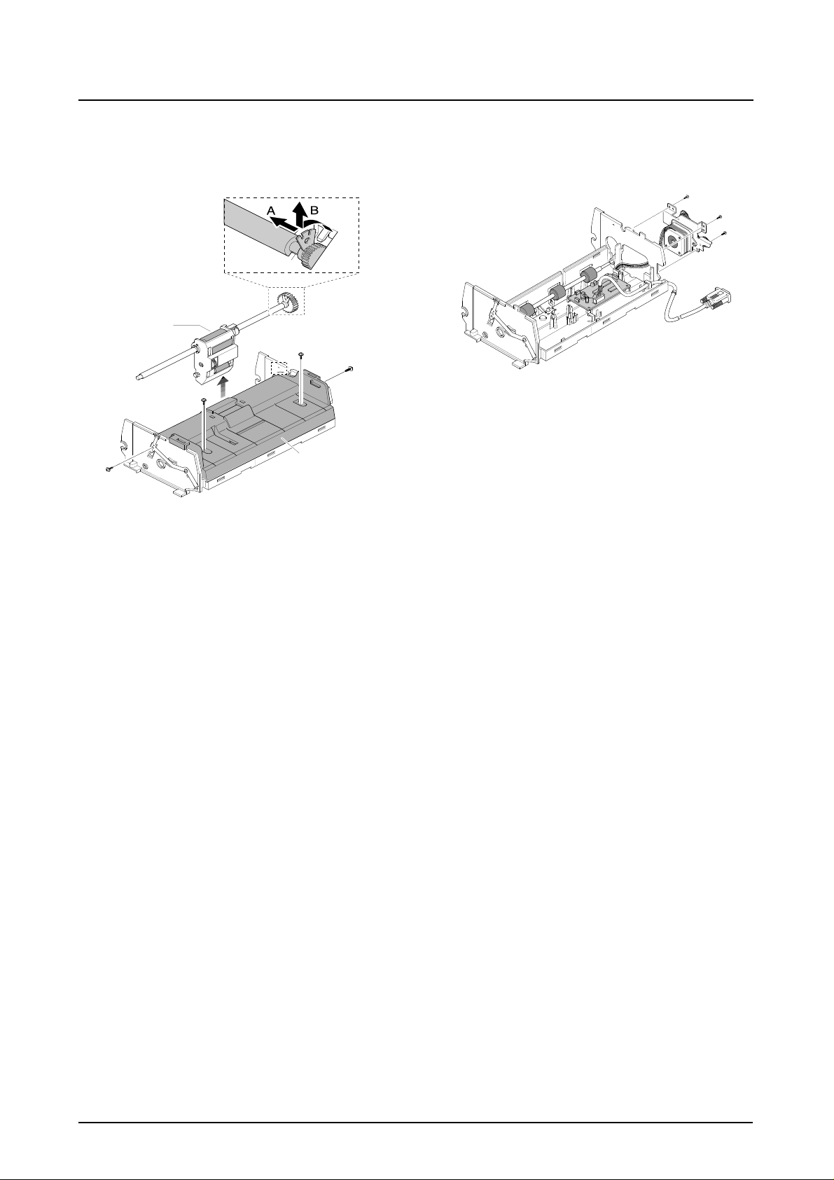
Disassembly and Reassembly
6. Take out the Pick-up Ass’y.
Remove the four screws and the ADF Upper.
Pick-up Ass’y
ADF Upper
7. Remove three screws and take out the ADF
Motor ass'y.
Samsung Electronics
3-7
Disassembly and Reassembly
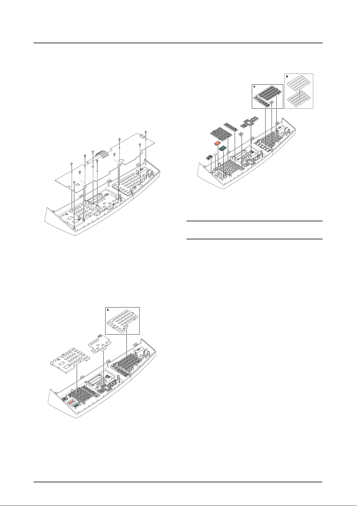
3-5 OPE Ass'y
1. Before you remove the OPE Ass'y, you should
remove:
- Rear Cover (see page 3-1)
- Scanner Ass'y (see page 3-2)
2. Remove ten screws securing the OPE PBA and
the LCD Module from the OPE Cover.
4. Remove the key pad from the unit.
Caution
The above information is for the SCX-5312 model.
For the SCX-5112 model, “A” parts is eliminated.
3. Remove the contact rubbers from the unit.
3-8
Samsung Electronics
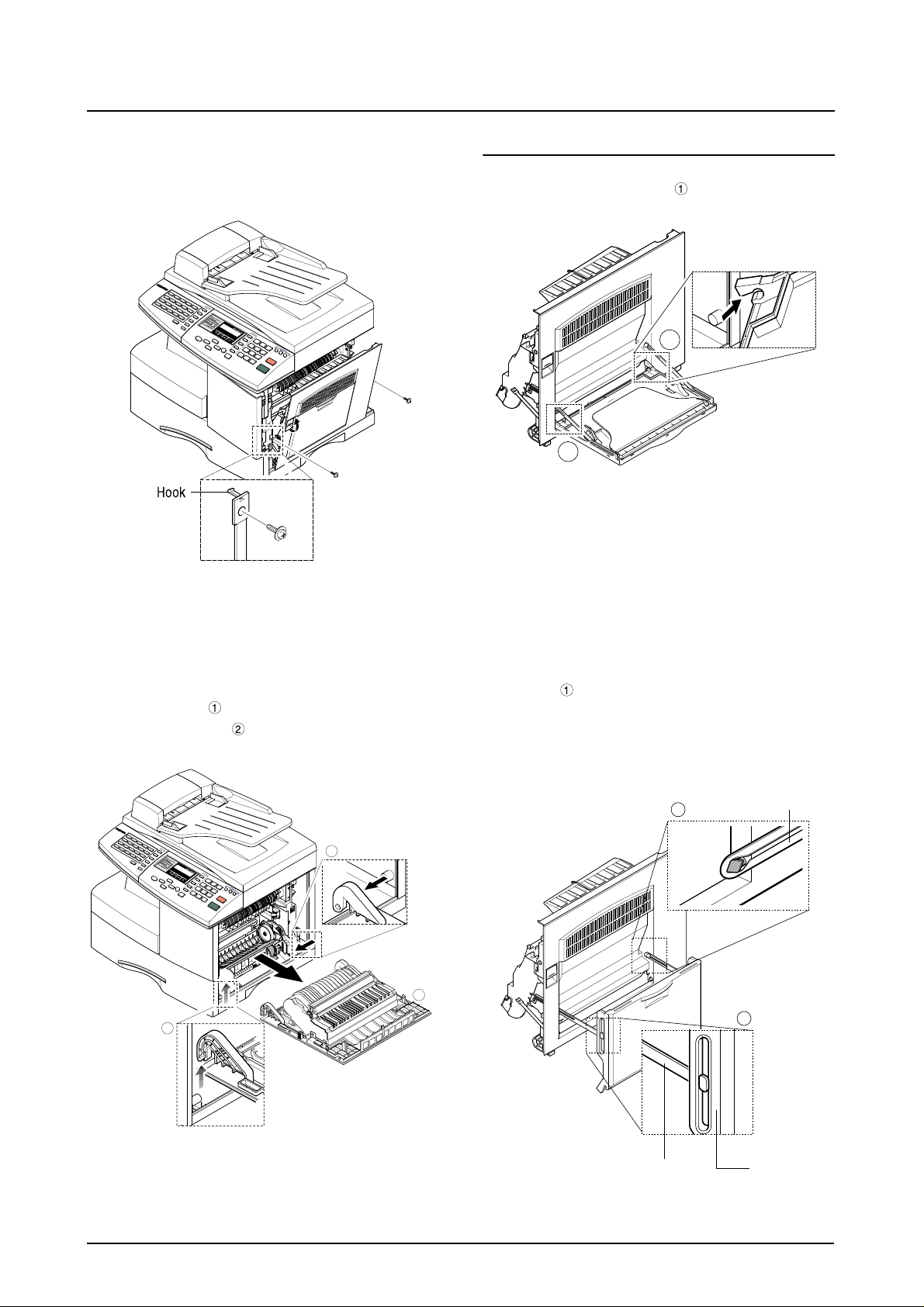
3-6 Side Cover Ass'y
Disassembly and Reassembly
1. Remove the two screws to release the Stopper(Main Frame side) securing the Side Cover
to the Main Frame.
* MP-Tray
1. Pull the both side of the part to dissemble it.
1
1
2. Completely open the Side Cover Ass’y, and
after pull the part to the arrow direction (to
the top), pull the part to the arrow direction
(inner side).
2
1
2. As the part, make the Tray-Case and the
Tray-Link in rectangular position to dissemble
the Tray-Case from the T ra y Link. The Tray Link
locates at an angle of 45˚ from the Side Cover
Ass’y and then remove the Tray Link.
2
3
MP Tray
1
Samsung Electronics
Tray Link
Tray-Case
3-9

Disassembly and Reassembly
* Duplex Ass’y
1. Unite the part and home to the projection
part of the Side Cover assembly, and widen
them from each other to dissemble the Side
Cover Ass’y.
Deplex Ass’y
* Transfer Roller Ass’y
1. Take out the Transfer Roller, as shown below.
3-10
Samsung Electronics

3-7 Fuser Ass'y
Disassembly and Reassembly
1. Before you remove the Fuser Ass'y, you should
be power off and remove:
- Side Cover Ass'y (see page 3-9)
2. Remove the one screw and take out the Cover
Sheet Connector.
3. Unplug the one connector.
6. Remove the two screws and take out the Halogen Lamp.
Halogen Lamp
5. Remove the four screws and take out the Thermostat.
Thermostat
4. Remo v e the three scre ws and tak e out the Fuser
Ass'y.
Samsung Electronics
7. After remove the two screw and open the Lower
Ass’y froward tack out the Heat Roller Ass’y
from Upper Fuser Ass’y.
Heat Roller
3-11

Disassembly and Reassembly
3-8 Exit Ass'y
1. Before you remove Exit Ass'y, you should
remove:
- Rear Cover (see page 3-1)
- Scanner Ass'y (see page 3-2)
2. Remo v e four scre ws, and then untile the harness
from the Exit Upper. Unplug four connectors and
unlatch the Dummy Base Frame, as shown
below.
3. Pull the exit ass’y and remove it.
3-9 Cover Paper Exit Ass'y
1. Before you remove the Cover Paper Exit Ass'y,
you should remove:
- Rear Cover (see page 3-1)
- Scanner Ass'y (see page3-2)
2. Remove two screws and Cover Paper Exit Ass'y,
as shown below.
Cover Paper Exit Ass’y
3-12
Samsung Electronics

3-10 Drive Ass'y
Disassembly and Reassembly
1. Before you remove the Drive Ass'y, you should
remove:
- Rear Cover (see page 3-1)
- Shield Main Upper (see page 3-2)
2. Unplug the two connectors.
(Main Motor:9pin, Duplex Solenoid : 2pin)
3. Remo ve the one screw and take out the Fan and
Dust Fan.
Fan
Dust Fan
4. Remove the five screws and take out the Drive
Ass'y.
Samsung Electronics
Drive Ass’y
3-13
Disassembly and Reassembly
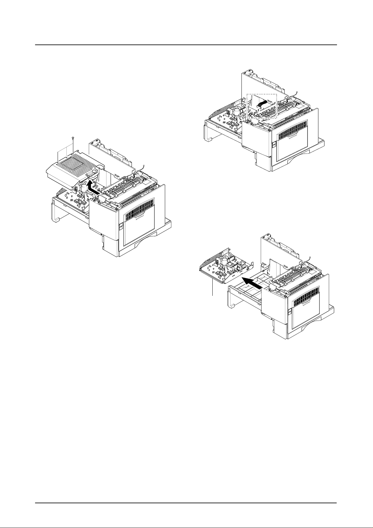
3-11 SMPS
1. Before you remove the LSU, you should remove:
- Rear Cover (see page 3-1)
- Scanner Ass'y (see page 3-2)
- Cover Paper Exit Ass’y(see page 3-12)
2. Remove three screws and take out the Shield
SMPS Upper.
3. Unplug the all connectors.
4. Remove the SMPS, as shown below.
SMPS
3-14
Samsung Electronics

3-12 LSU (Laser Scaning Unit)
Disassembly and Reassembly
1. Before you remove the LSU, you should remove:
- Rear Cover (see page 3-1)
- Scanner Ass'y (see page 3-2)
- Cover Paper Exit Ass’y (see page 3-12)
2. Unplug the two connectors.
3. Remo ve the three screws and tak e out the LSU.
LSU
Samsung Electronics
3-15

Troubleshooting
4. Maintenance & Troubleshooting
In this chapter, it was mentioned about the functions for maintaining the product, how to find the causes of the
inferiority, and troubleshooting method.
The service manual is bound the SCX-5312F and SCW-5112 together in one volume.
The SCX-5312F has functions such as printer, copy, scanner, and fax. The SCX-5112 has all functions as the
SCX-5312F but the fax function.
The contents of the manual are standardized for the SCX-5312F.
The information about the fax function is not applied for the SCX-5112.
The differences by each model are explained in a separate way.
4-1 Preventative Maintenance
The cycle period outlined below is a general guideline for maintenance.
The example list is for an average usage of 50 transmitted and received documents per day.
Environmental conditions and actual use will vary these factors.
The cycle period given below is for reference only.
COMPONENT REPLACEMENT CYCLE
ADF Rubber 20,000 Pages
ADF Roller 50,000 Pages
Pick-up Roller 75,000 Pages
Transfer Roller 75,000 Pages
Fuser 75,000 Pages
Toner Cartridge 6,000 Pages
Drum Cartridge 15,000 Pages
Samsung Electronics 4-1
Troubleshooting
4-2 Error Messages
Error Message Description Solution
RETRY REDIAL? The machine is waiting for the programmed inter-
val to automatically redial.
COMM. ERROR A problem with the f acsimile communications has
occurred.
DOCUMENT JAM Loaded document has Jammed in the feeder
When Document Jam aeeurred at ADF module
DOOR OPEN The side cover is not securely latched. Clear the cover until it clicks in place.
GROUP NOT AVAILABLE You have tried to select a group location where
only a single location number can be used, such
as when adding locations for a multi-dial operation.
LINE ERROR Your unit cannot connect with the remote
machine, or has lost contact because of a problem on the phone line. When the mechine has a
problem in cause of fax data reception step
LOAD DOCUMENT You have attempted to set up a sending opera-
tion with no document loaded.
MEMORY FULL The memory has become full. Either delete unnecessary documents, or
You can press START to immediately
redial, or STOP to cancel the redial
operation.
Try again.
Clear the document Jam.
Try again, check location for group.
Try again. If failure persists, wait an
hour or so for the line to clear then try
again.
Load a document and try again.
retransmit after more memory becomes
available, or split the transmission into
more than one operation.
NO ANSWER The remote machine was not answered after all
the redial attempts.
NO. NOT ASSIGNED The speed dial location you tried to use has no
number assigned to it.
NO PAPER
[ADD PAPER]
OVERHEAT The printer part has overheated. Your unit will automatically return to the
PAPER JAM 0
OPEN/CLOSE DOOR
PAPER JAM 1/2
OPEN/CLOSE DOOR
TONER LOW Toner may be low Toner may be unevenly distributed.
TONER EMPTY When the machine has encountered the Toner
DRUM WARNING When the machine has encountered the drum
The recording paper has run out. The printer system stops.
Recording paper has jammed in paper feeding
area.
Recording paper is jammed in pick-up unit
Recording paper has jammed inside the unit.
Recording paper has jammed in paper exit unit.
Empty.
life,14000 print pages.
Try again.
Make sure the remote machine is OK.
Dial the number manually with the keypad, or assign the number.
Load the recording paper in the paper
feeder.
standby mode when it cools down to normal operating temperature. If failure persists, call service.
Press STOP and clear the jam.
Clear the jam.
Remove the toner cartridge and shake it
gently to evenly distribute the toner . Then
replace the toner cartridge.
Replace the Toner Cartridge.
Use little more change if “REPLACE
DRUM” is marked in LCD window.
REPLACE DRUM When the machine has encountered the out of
from lifr, 15000 print pages.
4-2
Replace the Drum Cartridge.
Samsung Electronics

Troubleshooting
Error Message Description Solution
NO CARTRIDGE When the machine detected the toner cartridge
Install the Cartridge.
has not been installed.
BYPASS JAM When the machine detected the non-feeding from
Open the side Cover and clear the jam.
BYP ASS Tray .
DUPLEX JAM When the machine detected the duplex jam in the
Clear the jam.
middle of machine.
LINE BUSY The remote FAX didn’t answer Try again.
OPEN HEAT EROR Thermister does not connected to main board or
contact point is not coupled tightly in power on.
Check thermister contact point, Heating
Camp & Thermostat.
Heating Error During operation, Temperatare does not go up. Check thermister contact point & Heating
Lamp.
Scanner Locked Scanner is locked by locker. Check locker.
Connect the Flat-Cable.
Samsung Electronics 4-3

Troubleshooting
4-3 User Mode
The table in the bellow explains the possible setting functions by user. The details about the ways to use are
explained in the user manual.
In the service manual, the items are about the possible set-up by user.
4-3-1 SCX-5312F
Function Item Content
SYSTEM DATA CASSETTE PAPER LETTER / A4 / LEGAL
BYPASS PAPER LETTER / A4 / LEGAL
MESSAGE CONF. ON / OFF / ERROR
AUTO JOURNAL ON / OFF
RECEIVE CODE 0-9
POWER SAVE ON / OFF
ECM MODE ON / OFF
RX REDUCTION ON / OFF
DISCARD SIZE 0-30mm
REDIAL INTERVAL 1-15
REDIALS 1-13
ANSWER ON RING 1-7
SEND FROM MEMORY ON / OFF
LOCAL ID ON / OFF
CLOCK MODE 12 / 24 HOUR
SYSTEM ID FAX / ID
DATE & TIME
SYSTEM SETUP PREFIX DIAL NO.
RINGER VOLUME LOW / HIGH (10 STEPS)
ALARM SOUND ON / OFF
KEY SOUND ON / OFF
SPEAKER CONTROL COM / ON /OFF
SELECT LANGUAGE ENG/GER/FRE/ITA/SPA/POR/DUT
USB MODE FAST / SLOW
FAX DUPLEX OFF / LONG EDGE / SHORT EDGE
IMAGE QUALITY NORMAL / TEXT / IMAGE
MEMORY CLEAR SYSTEM ID
SYSTEM DATA
PHONE BOOK / MEMORY
TX-RX JOURNAL
DELA Y TX
MEMORY TX
PRIORITY TX
POLLING
ADD/CANCEL ADD / CANCEL
GROUP DIAL
MAINTENANCE CLEAN DRUM
NEW DRUM
NOTIFY TONER LOW ON / OFF
4-4
Samsung Electronics

Function Item Content
TX CONFIRM
SCHEDULE JOB
PHONE BOOK
SYSTEM LIST
TX JOURNAL
RX JOURNAL
HELP LIST HELP LIST
4-3-2 SCX-5112
Function Item Content
SYSTEM DATA CASSETTE PAPER LETTER / A4 / LEGAL
BYPASS PAPER LETTER / A4 / LEGAL
POWER SAVE ON / OFF
SELECT LANGUAGE ENG/GER/FRE/ITA/SPA/POR/DUT
USB MODE FAST / SLOW
HELP LIST HELP LIST PRINTOUT
MAINTENANCE CLEAN DRUM
NEW DRUM
REPORTS SYSTEM DATA
HELP LIST HELP LIST
Troubleshooting
4-4 T ech Mode
4-4-1 How to Enter Service Mode
In service mode (tech) mode, the technician can check the machine and perform various test to isolate the
cause of a malfunction.
To enter the Tech mode, press MENU, #, 1, 9, 3, 4 in sequence, and the LCD briefly displays ‘T’, the
machine has entered service (tech) mode.
While in Tech mode, the machine still performs all normal operations.
To return to normal user mode, press MENU, #, 1, 9, 3, 4 in sequence again, or turn the power off, then on
by unplugging and plugging the power cord.
Options changed while in service mode do not remain changed unless you clear the machine’s memory.
Samsung Electronics 4-5

Troubleshooting
4-4-2 Setting-up System in Tech Mode
4-4-2-1 SCX-5312F(SETUP : #, 1, 9, 3, 4)
Function Item Content
SYSTEM DATA DIAL MODE TONE / PULSE
MODEM SPEED
ERROR RATE 5% /10%
SET TX LEVEL 09-15
SILENCE TIME 12 / NU / OFF
SYSTEM ID The same as User Mode
DATE & TIME The same as User Mode
SYSTEM SETUP The same as User Mode
MEMORY CLEAR CLEAR ALL MEMORY
DELAY TX The same as User Mode
MEMORY TX The same as User Mode
PRIORITY TX The same as User Mode
POLLING The same as User Mode
ADD/CANCEL The same as User Mode
GROUP DIAL The same as User Mode
MAINTENANCE CLEAN DRUM
NEW DRUM
NOTIFY TONER LOW ON / OFF
SWITCH TEST
MODEM TEST
SRAM TEST
DRAM TEST
ROM TEST FLASH / ENGINE
PATTERN TEST PATTERN1-7, QAPATTERN1-4, ALL"1-7 , ALL"
CLEAR COUNT PASSWORD
CRU PRINTS COUNT
FLT SCAN COUNT
ADF SCAN COUNT
USED DRUM COUNT
USED TONER COUNT
TOTAL PAGE COUNT
ANSWER ON CNG 1-4
ADJUST SHADING
FLASH UPGRADE LOCAL
REMOTE : USER PROGRAM ,
EMULATION ,BOOT PROGRAM
PROGRAM DIAL
TX CONFIRM The same as User Mode
SCHEDULE JOB The same as User Mode
PHONE BOOK The same as User Mode
SYSTEM LIST USER MODE
TX JOURNAL The same as User Mode
RX JOURNAL The same as User Mode
4-6
Samsung Electronics
 Loading...