

Page 1
Troubleshooting
5. Troubleshooting
In this chapter, it was mentioned about the functions for maintaining the product, how to find the causes of the
inferiority, and troubleshooting method.
5-1 Preventative Maintenance
The cycle period outlined below is a general guideline for maintenance.
The example list is for an average usage of 50 transmitted and received documents per day.
Environmental conditions and actual use will vary these factors.
The cycle period given below is for reference only.
COMPONENT REPLACEMENT CYCLE
ADF Rubber 50,000 Pages
ADF Roller 50,000 Pages
Pick-up Roller 50,000 Pages
Transfer Roller 50,000 Pages
Fuser 50,000 Pages
Toner Cartridge 6,000 Pages
Drum Cartridge 15,000 Pages
5-2 Error Messages
ERROR MESSAGE DESCRIPTION SOLUTION
[BYPASS JAM] When the machine detected the non-feeding from
BYP ASS Tray .
COMM. ERROR A problem with the facsimile communications has
occurred.
DOCUMENT JAM Loaded document has Jammed in the feeder
When Document Jam aeeurred at ADF module
[DOOR OPEN ] The side cover is not securely latched. Clear the cover until it clicks in place.
DRUM WARNING When the machine has encountered the drum
life,14000 print pages.
[DUPLEX JAM]
OPEN/CLOSE DOOR
GROUP NOT AVAILABLE You have tried to select a group location where
HEATING ERROR During operation, Temperatare does not go up. Check thermister contact point & Heating
When the machine detected the duplex jam in the
middle of machine.
only a single location number can be used, such
as when adding locations for a multi-dial operation.
Open the side Cover and clear the jam.
Try again.
Clear the document Jam.
Use little more change if “REPLACE
DRUM” is marked in LCD window.
Clear the jam.
Try again, check location for group.
Lamp.
LINE ERROR Your unit cannot connect with the remote
machine, or has lost contact because of a problem on the phone line. When the mechine has a
problem in cause of fax data reception step
Try again. If failure persists, wait an
hour or so for the line to clear then try
again.
5-1
Page 2

Troubleshooting
ERROR MESSAGE DESCRIPTION SOLUTION
INVALID
CARTRIDGE
You have used unauthorised cartridge. You must use a Samsung approved car-
tridge.
LINE BUSY The remote FAX didn’t answer Try again.
LOAD DOCUMENT You have attempted to set up a sending opera-
Load a document and try again.
tion with no document loaded.
MEMORY FULL The memory has become full. Either delete unnecessary documents, or
retransmit after more memory becomes
available, or split the transmission into
more than one operation.
NO ANSWER The remote machine was not answered after all
the redial attempts.
NO DEVELOPER
CARTRIDGE
When the machine detected the toner cartridge
has not been installed.
NO. NOT ASSIGNED The speed dial location you tried to use has no
number assigned to it.
[NO PAPER]
ADD PAPER
[PAPER JAM 0]
OPEN/CLOSE DOOR
The recording paper has run out. The printer system stops.
Recording paper has jammed in paper feeding
area.
Try again.
Make sure the remote machine is OK.
Install the Cartridge.
Dial the number manually with the keypad, or assign the number.
Load the recording paper in the paper
feeder.
Press STOP and clear the jam.
Recording paper is jammed in pick-up unit
[PAPER JAM 1]
OPEN/CLOSE DOOR
[PAPER JAM 2]
Recording paper has jammed inside the unit.
Recording paper has jammed in paper exit unit.
Paper has jammed in the paper exit area.
Clear the jam.
CHECK INSIDE
[TONER EMPTY] When the machine has encountered the Toner
Replace the Toner Cartridge.
Empty.
[TONER LOW] The toner is almost empty. Take out the toner cartridge and gently
shake it. By doing this, you can temporarily re-establish printing operations.
REPLACE DRUM When the machine has encountered the out of
Replace the Drum Cartridge.
from lifr, 15000 print pages.
RETRY REDIAL? The machine is waiting for the programmed inter-
val to automatically redial.
You can press START to immediately
redial, or STOP to cancel the redial
operation.
OPEN HEAT EROR Thermister does not connected to main board or
contact point is not coupled tightly in power on.
Check thermister contact point, Heating
Camp & Thermostat.
[OVERHEAT] The printer part has overheated. Your unit will automatically return to the
standby mode when it cools down to normal operating temperature. If failure persists, call service.
SCANNER LOCKED Scanner is locked by locker. Check locker.
Connect the Flat-Cable.
5-2
Page 3

Troubleshooting
5-3 T ech Mode
5-3-1 How to Enter Service Mode
In service mode (tech) mode, the technician can check the machine and perform various test to isolate the
cause of a malfunction.
To enter the Tech mode, press MENU, #, 1, 9, 3, 4 in sequence, and the LCD briefly displays ‘T’, the
machine has entered service (tech) mode.
While in Tech mode, the machine still performs all normal operations.
To return to normal user mode, press MENU, #, 1, 9, 3, 4 in sequence again, or turn the power off, then on
by unplugging and plugging the power cord.
Options changed while in service mode do not remain changed unless you clear the machine’s memory.
5-3-2 SYSTEM DATA
DIALING MODE
Select the dialing mode according to the user's line status.
• TONE: Electrical type of dial
• PULSE: Mechanical type of dial
SILENCE TIME
In ANS/FAX mode, after a call is picked up by the answering machine, the machine monitors the line. If a
period of silence is detected on the line at any time, the call will be treated as a fax message and the machine
begins receiving.
Silence detection time is selectable between limited (about 12 seconds) and unlimited time.
When '12 sec' is selected, the machine switches to receiving mode as soon as it detects a period of silence.
When 'unlimited'is selected, the machine waits until the answering operation is concluded even though a
period of silence is detected. After the answering operation is concluded, the machine switches to receiving
mode.
SEND FAX LEVEL
You can set the level of the transmission signal. Typically, the Tx level should be under -12 dBm.
Caution: The Send Fax Level is set at the best condition in the shipment from factory. Never change
settings arbitrarily.
ERROR RATE
When the error rate is about to be over the setting v alue, the Baud r ate automatically lo wers up to 2400 bps to
make the error rate remain below the setting value.
You can select the rate between 5% and 10%.
MODEM SPEED
You can set the maximum modem speed.
Communication is done with modem speed automatically set at lower speed when communicating with the
modem with lower speed since communication is done on the standard of the side where modem speed is low
for transmission/reception. It is better set 33.6Kbps as default setting.
5-3
Page 4

Troubleshooting
5-3-3 MEMORY CLEAR
CLEAR ALL MEMORY
The function resets the system as its very first condition as setting in at the factory.
This function is needed to operate to reset the system to the initial value when the product is abnormally operated or malfunction. All the values are returned to the default values, and all the information, which set in by
user, will be erased.
< Method >
1. Select the [MEMORY CLEAR] at the TECH MODE.
2. Push the ENTER button.
3. Select you country.
4. Push the ENTER button then it will be all memory clear. .
NOTICE : Always perform the memory clear after replace the main board. Otherwise, the system may
not operate properly.
5-3-4 MAINTENANCE
CLEAN DRUM
Use this feature to get rid of the toner remained in the development unit, so you can get a clean printout.
Perform this feature if stains or specks appear on the printing materials and print quality falls.
Perf orm this feature several times until a clean printing material appears. The machine automatically pulls in a
sheet of paper,and prints out.The toner particles on the OPC drum surface is fixed to the paper.
FLASH UPGRADE
It is Firmware Upgrade function and has two methods, Local and Remote.
More information can be found in the firmware upgrade items.
ADJUST SHADING
The function is to control to get the optimum scan quality by the specific character of the CCD(Charge Coupled Device). If the copy image quality is unsatisfied, perform the function to check the condition of the print
out for checking whether or not having CCD trouble.
< Method >
1. Select the [ADJUST SHADING] at the TECH MODE.
2. Push the SET UP button then an image will be scanned.
3. After the scan, CCD SHADING PROFILE will be print out.
4. If the printed image is different to the image, the CCD is defect.
NOTICE :
that the cover is closed.
When you test CCD, make sure
5-4
Page 5

Troubleshooting
ANSWER ON CNG
The function is to control the CNG TONE cognition times for entering receiving mode from the AUTO MODE
or ANS/FAX MODE
CLEAR COUNT
This function erases information of history such as replacement times of Developing part and OPC drum,
total printing pages, scan times, and etc.
• The items are in the below section of the System Data List, printed at TECH MODE.
• PASSWOEED: 1934
• Current Drum Page Count cannot be erased.
It is possible to erase at NEW DRUM function (USER MODE ⇒ MINTENANCE ⇒ NEW DRUM)
FIRMWARE VERSION : 1.00
ENGINE VERSION : 1.00
EMULATION VERSION : PCL6 2.32 07-11-2001
TOTAL PAGE COUNTS : 123
CRU PRINTS : 123
REPLACED TONER COUNTS : 1
REPLACED DRUM COUNTS : 1
CURRENT DRUM COUNTS : 112
PLATEN SCAN PAGE COUNTS : 23
ADF SCAN PAGE COUNTS : 10
PCL5e 1.48 07-19-2001
< SYSTEM DATA LIST >
P A TTERN TEST
Using this pattern printout, you can check if the printer mechanism is functioning properly.
It is needed in the production progress. Service person doesn't need to use it.
ROM TEST
Use this feature to test the machine'S ROM. The result and the software version appear in the LCD display.
• FLASH VER : 1.00 V • ENGINE VER :1.00V
DRAM TEST
Use this feature to test the machine's DRAM. The result appears in the LCD display.
If all memory is working normally, the LCD shows << O K >>
SRAM TEST
Use this feature to test the machine's SRAM. The result appears in the LCD display.
If all memory is working normally, the LCD shows << O K >>
MODEM TEST
Use this feature to hear various transmission signals to the telephone line from the modem and to check the
modem. If no transmission signal sound is heard, it means that the modem part of the main board is poor.
5-5
Page 6

Troubleshooting
SWITCH TEST
Use this feature to test all keys on the operation control panel. The result is displayed on the LCD window
each time you press a key.
NOTIFY T ONER LOW
With this feature enabled, when the toner becomes low, the toner low information will be sent to ta specified
contact point, for example, the service company. After you access this menu, select ON, and when the LCD
prompts, enter the name and the number of the contact point, the customer's fax number, the model name,
and the serial number.
PROGRAM DIAL
It is a function setting transmitting conditions to transmit to specific address preliminary.
When user transmit specific address set this function, the conditionsapplied automatically.
5-6
Page 7

Troubleshooting
5-3-5 REPORT/HELP
MSG. CONFIRM
It shows the result of the last send operation.
PROTOCOL LIST
This list shows the sequence of the CCITT group 3 T.30 protocol during the most recent sending or receiving
operation. Use this list to check for send and receive errors. If a communication error occurs while the
machine is in TECH mode, the protocol list will print automatically.
Facsimile Information Field
data described in hexdecmal code
Sending/Receiving
PROTOCOL DUMP LIST NOV-20-2001
S/R FCF FIF DATA! ASCII
S NSF 61005820003380140200001302090018010000
S CSI 2020202020202020202020202O20202020202020
S DIS 00000000 01110111 00010111 00100010
S NSF 61005020003380140200001302090018010000
S CSI 202020202020202020202022O202020220202020
S DIS 00000000 01110111 00010111 00100010
R TSI 2020202020202020202020202O20202020202020
R DCS 00000000 01100001 00010101 00000000
S FTT
R TSI 2020202020202020202020202O20202020202020
R DCS 00000000 01100001 00010101 00000000
S CFR
R MPS
S MCF
S DCN
Name of signal
(Facsimile Control Field)
FIF data described
in ASCII code
HELP
It shows a brief description on the machine's basic functions and commands.Use it as a quick reference guide
RECEPTION
This journal shows a specific information concerning reception activities, the time and dates of up to 40 of the
most recent receptions.
TRANSMISSION
This journal shows a specific information concerning transmission activities, the time and dates of up to 40 of
the most recent transmissions.
SYSTEM DATA
This list provides a list of the user system data settings and tech mode settings.
PHONEBOOK
It lists all telephone numbers that have been stored in the machine.
SCHEDULE JOB
This list shows a specific information on the documents currently stored for delayed transmission. It provides
the operation number, starting time, type of operation, etc.
ERROR CODE
It shows error history occurred using product.
5-7
Page 8

Troubleshooting
5-3-6 Firmware Upgrade
It is a new Firmware, and there are two Upgrade methods by local and remote.
5-3-6-1 Local Machine
RCP(Remote Control Panel) mode
This method is for Parallel Port.or USB Port Connect to PC and activate RCP(Remote Control Panel) to
upgrade the Firmware.
< Method >
How to Update Firmware using RCP
1. Connect PC and Printer with Parallel Cable or USB Cable.
2. Ex ecute RCP and select Firmware Update. Current Firmware version and Emulation Version are displayed
on Current version window.
3. Search Firmware file to update with Browse Icon.
4. Click Update icon, firmware file is transmitted to Printer automatically and printer is initialized when it finished.
5. Click Refresh icon and check what is updated.
DOS Command mode
This method is just for Parallel Port. Connect to PC with Parallel cable and enter DOS Command to upgrade
the Firmware.
< Method >
a). The first of all, need the files : down.bat, down_com.bin, fprt.exe, and Rom File : file name for upgrade.Save the files in the
same folder.
b). In the DOS, input as below and push the enter key. Then, it will be automatically upgraded.
c) There are two commands for the conditions of product.
* When the product is in idle condition
down "rom file"
* When the product is in idle condition(TECH MODE → MAINTENANCE → FLASH UPGRADE → LOCAL)
fprt "rom file"
d) Do not turn off the power while upgrading process.
Remote FAX
This is a function that a fax with the latest firmware sends files to a fax in long distance through telephone line.
< Method >
1. Operate a fax with the latest firmware to prepare it being upgrade.
(TECH MODE MAINTENANCE FLASH UPGRADE REMOTE)
2. Input the fax number, which needs to be upgraded.
(Several faxes can be upgrade at the same time. In this case, enter the each fax number.)
3. After push the enter button, send the firmware file by calling to the appointed number.
(Around 10~15 minutes needs to send the file.)
< Caution >
1. sending and receiving fax must be the same model.
2. A sending fax must be set up as ECM mode, and a receiving memory must be set up as 100%.
If not, the function operates abnormally.
5-8
Page 9

Troubleshooting
5-4 ENGINE TEST MODE
The Engine Tests Mode supplies useful functions to check conducting condition of engine. It tests the conducting condition of each device and displays the result of the test at the LCD. It is classified in 6. items (0~5),
and the functions of items are as bellows.
5-4-1 To enter the Engine Test Mode
Press MENU, #, 1, 9, 3, 1 in sequence, and the LCD briefly displays ‘T’, the machine has entered service
(tech) mode.
5-4-2 Diagnostic
No. Sub No. Engine tes t
0 1 Motor Test 1: On, 2: Off
2 PTL Test 1: On, 2: Off
3 Fan Test 1: On, 2: Off
: On, 2: Off
4 Fuser Test
1 1 LSU Motor Test 1: On, 2: Off
2 LSU Hsync Test 1: On, 2: Off
3 LD On Test 1: On, 2: Off
4 LSU Operation 1: On, 2: Off
2 1 Feed Sensor Test Sensor O n : FEED SENSOR ON D isplay
2 Exit Sensor Test Sensor On : EXIT SENSOR ON Display
3 Cov er Sensor Test Se nsor On : COVER SENSOR ON Display
4 1’st CAST Emp ty Test Sensor O n : 1’st PAPER Em pty Displa y
5 MP Empty Sen Test Sensor O n : MP PAPER Em pty Display
6 BIN FULL Sen TEST Sensor On : BIN F ULL SEN ON D isplay
3 1 1’st C AST Solenoid Test 1: On, 2: Off
2 MP Solenoi d Test 1: On, 2: Off
3 Duplex Solenoid Test 1: On, 2: Off
4 1 MHV Test 1: On, 2: Off ( -1450v)
2 Dev Bias Test 1: On, 2: Off ( -450v)
3 THV EN/NEG Test 1: On, 2: Off
4 THV Test 1: On, 2: Off ( 1300v)
5 THV Trigger T est 1: On, 2: Off
5 1 All Function Test
1
If its temperature is lower than the Standby
(160 C), the fuser is on, but if it is higher than
the Standby, the fuser is off.
Sensor O ff : FEED SENSOR OFF Display
Sensor Off : EXIT SENSOR OF F D isplay
Sensor O ff : COVER SENSOR OFF Display
Sensor O ff : 1’st PAPER N o Empty D isplay
Sensor O ff : MP PAPER No E mp ty Display
Sensor O ff : BIN FULL SEN OFF D isplay
For SMD Test, Push up key : Next function
All Function : N o.0~4
Remark
5-4-3 ENGINE PRINT
When the function is on, sentence to explain the condition of engine is printed in the below section of the printing output.
It is needed in the development progress. Service person doesn't need to use it.
5-9
Page 10
Troubleshooting
5-5 Troubleshooting
5-5-1 Scanner
5-5-1-1 COPY
PROBLEM ITEMS TO BE CHECKED. HO W TO SOLVE
White copy • Check the Scan-Cover open. • Room light can transit a thin original.
• Check shading profile. • Remake shading profile in the tech mode.
• Check white/black reference voltage in
Main PBA.
• Check turning the CCD Lamp on when
operating.
Black copy • Check the CCD problem in Main PBA. • Check the CCD harness contact.
• Check shading profile. • Remake shading profile in the tech mode.
• Check the CCD problem in Main PBA. • If the CCD is defective, replace it.
Defective image quality • Check shading profile. • Remake shading profile in the tech mode.
• Check the gap between original and scan-
ner glass.
• Check printing quality. • See “Print” troubleshooting.
Abnormal noise • Check the Scanner Motor and any
mechanical disturbance.
• Replace U16 if it is defective.
- U16-97 = 2.5V - U16-98 = 3.3V
- U16-99 = 1.5V
• If the CCD is defective, replace it.
- CN3-19 is 5.8V when white original copying for R, B and 3.5V for G.
- Cn3-19 is 7.3V when idle for R, B, and 5V
for G.
• The gap above 0.5mm can cause a
blurred image.
• Check the right position of the Scanner
Motor, and check the any mechanical disturbance in the CCD carriaging part.
5-10
• Check the Motor Driver in Driver PBA. • If any driver is defective, replace it.
- U55-1 or U55-15 = 0V to 24V swing signal
when operating.
Page 11

Troubleshooting
5-5-1-2 PC-Scan
PROBLEM ITEMS TO BE CHECKED. HO W TO SOLVE
Scanning Error • Check the printer cable installed. • Check correct installation, and use stan-
dard IEEE1284 cable.
• Check how TWAIN driver is installed. • Remove any other scanner driver.
• Reboot after reinstallation of the TWAIN
driver.
• Check the printer port(Parallel). • Check the parallel-port-related items in the
CMOS Setup.
As a printer port, Select ECP among
SPP(Normal), ECP, and EPP
modes(increase print-ing speed)
• Check harness contact.
.
• Check the IEEE1284 signal level. • If any signal level is defective, replace
• Check the USB signal level. • If USB signal level is defective, replace
Defective image
Quality
Abnormal noise • Check the Scanner Motor and any
• Check shading profile. • Remake shading profile in the tech mode.
• Check the gap between original and scan-
ner glass.
mechanical disturbance.
• Check the motor driver in Driver PBA. • If any driver is defective, replace it.
• Check CN14 contact in Main PBA
Driver PBA.
- U36-66~74 in Main PBA = 0.8V to 2.4V
TTL signal.
• Otherwise, replace Main PBA.
Main PBA.
• The gap above 0.5mm can cause a
blurred image.
• Check the right position of the Scanner
Motor, and check the any mechanical disturbance in the CCD carriaging part.
- U55 or U56-1 = 0V to 24V swing signal
when operating.
5-11
Page 12

Troubleshooting
5-5-2 FAX
5-5-2-1 FAX/TELEPHONE Precautions
PROBLEM ITEMS TO BE CHECKED. HO W TO SOLVE
TEL LINE CANNOT BE
ENGAGED
(NO DIAL TONE)
• When you press “ OHD” key:
a) Check line cord connection.
b) Check MAIN LIU harness, and CN1
(LIU PBA).
c )Check relay operation of LIU PBA :
Is the control signal of CN20-7(main) low?
a) insert it correctly into the connection
jack called “line”.
b) Replace defective parts.
c) Replace main PBA IF the control signal
of CN20-7(main) is high.
Replace LIU PBA if high but phone line
cannot be connected.
Cannot MF dial • Check CN20 (main PBA), MAIN-LIU
harness, and CN1 (LIU PBA)
MF dial is possible but
not DP dial.
Defective fax transmission
Defective automatic f ax
reception
• Check DP control signal of CN20-11 of
MAIN PBA and the circuit around R15. U6
and Q2 of Liu PBA.
• Check CN20 (main PBA), MAIN LIU
harness, and CN1(LIU PBA).
• Is the external phone hooked off?
• Check ‘hook off’ : Refer to ‘TEL LINE
CANNOT BE ENGAGED’ above.
• Check the control signals of CN20-11.
• Check transmission path : Check output of
CN20-3.4 and T2-4(LIU PBA).
• Check reception path : Check output CN1 1 (LIU PBA) and input of CN20-1
(main PBA).
• Is the ring checked?
Check ring pattern at CN1-9 (LIU PBA).
• Refer to ‘Defective Transmission. ’
• Replace defective parts.
• Replace LIU PBA.
• Replace defective parts.
• Replace LIU PBA if low.
• Refer to ‘TEL LINE CANNOT BE
ENGAGED’ above.
• Replace main PBA, if the signals of CN8-
11 (MAIN PBA) is low.
• Replace main PBA, if abnormal.
• Replace LIU PBA if CN1-1(LIU PBA) is not
confirmed.
Replace main PBA if CN20-1(MAIN PBA)
is not confirmed.
• Replace LIU PBA if it cannot be checked.
• Refer to ‘Defective Transmission’.
5-12
Page 13
5-5-3 Print Quality
Error Status Check Solution
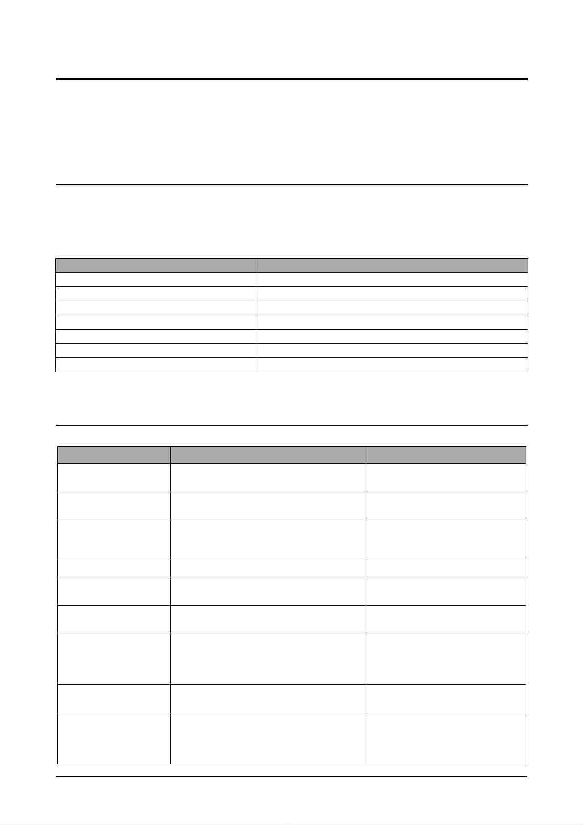
Vertical blac k line and
band
Digital Printer
Digital Printer
Digital Printer
Digital Printer
Digital Printer
1. Bad blade of Toner cartridge
2. LSU
1. Change Toner cartridge
2. Replace LSU
Troubleshooting
Vertical white line
Digital Printer
Digital Printer
Digital Printer
Digital Printer
Digital Printer
No image
Digital Printer
Digital Printer
Digital Printer
Digital Printer
Digital Printer
Light image
Digital Printer
Digital Printer
Digital Printer
Digital Printer
Digital Printer
1. LSU window contamination
2. Toner cartridge
1. Seal tape is removed?
2. GND OPC is well grounded?
3. LSU running well?
4. Biss voltage is normal?
5. Lower toner?
6. Is there video data from Main PBA
1. Check seal tape removing
2. LSU light power normal?
3. Enough toner?
4. High charger voltage?
5. Lower bias voltage
6. Contamination of high voltage contact.
7. Transfer volatge and roller.
1. Clean LSU window
2. If not LSU, change Toner cartridge.
1. Removing seal tipe
2. Measure the resistance between frame
ground and the ground spring attached
frame. Confirm stable ground. Unless bad
ground, detach cabinet, check where is
bad point
3.Adjust LSU or replace it
4. Normal Dev bias = -350V
5. Shake toner cartridge and print.If a liitke
good, toner is empty
6. Test engine test pattern , replace Main
PBA
1. Check and remove tape
2. LSU light power check is difficult.
Compare with new one and check.
3. Check toner and developer counter
4~5. Measure all high voltage output.
6. Leakage toner cause bad contact and
increase contact resistance. Clean contaminated area.
Dark image
Digital Printer
Digital Printer
1. LSU light power normal?
2. Bias voltage output is high?
3. Video data is always supplied?
1. Check the rated level and replace.
2. Set to power rating.
3. Replace defected board.
5-13
Page 14

Troubleshooting
Error Status Check Solution
Background
1. High voltage output is normal?
2. C/R of Toner cartridge is contaminated?
1. Adjust to the rated status.
2. Replace Toner cartridge.
Digital Printer
Digital Printer
Digital Printer
Digital Printer
Digital Printer
Ghost
Digital Printer
Digital Printer
Digital Printer
Digital Printer
Digital Printer
Digital Printer
Stains on back of
paper
Poor Fusing 1. Use recommended paper?
1. High voltage output.
2. Pre-Transfer Lamp.
3. Bad high voltage contact.
1. Contamination of transfer roller.
2. Stains of paper path.
3. Pressure roller’s contamination.
2. Check fusing temperature.
3. The machine was under the low tempera
ture for a long time?
1. Check every high voltage.
2. Check the turn-on PTL, LED crash.
3. Clean the inside machine or replace toner
cartridge.
1. Clean the transfer roller with vaccum
cleaner.
2. Clean the area of paper path with cloth or
air cleaner.
3. Remove fuser and replace it.
1. Should use recommended paper.
2. Check engine controller board.
If you have not thermometer, measure
the thermistor voltage to CPU, If 2.3V±5%
in printing CPU works well. Then, disas-
semble fuser and check the thermistor
contact and thermistor.
3. Re-check after putting the machine in the
warm place for certain period.
Partial blank image
(not periodic)
5-14
1. Toner is low?
2. The toner cartridge is out of position?
1. Replace Toner cartridge.
2. Checkand adjust.
Page 15

Error Status Check Solution
Partial blank image
(periodic)
1. Develope roller scar or particle.
2. Scar or particle. (94 mm)
3. Transfer roller scar or particle .
(47 mm)
1~2. Replace toner cartridge.
3. Replace transfer roller.
Troubleshooting
Different image density
(left and right)
Horizonral band 1. Unstable high voltage contact
Digital Printer
Digital Printer
1. Charge roller’s pressure force unbalance
2. Dev. roller and OPC or Dev. roller and
blade’s pressure force unbalance
3. Transfer roller’s pressure force unbalance
of each side
2. Charge roller’s contamination
3. Contamination of heat roller
4. Malfunction of LSU
Digital Printer
Digital Printer
Digital Printer
1~2. Change toner cartridge
3. Chec k left and right spring of transf er roller
and the spring pressing the developer
inside the machine
1. Clean each contact and check good con-
tact
2. Clean charge roller
3. Replace fuser unit
4. Check Main PBA.
Abnormal Image Printing and Defective Roller
If abnormal image prints periodically, check the parts shown below
NO Roller Abnormal image period Kind of abnormal image
1 OPC Drum 94.3 mm White spot. Black spot
2 Charge Roller 37.7 mm White spot. Black spot
3 Supply Roller 35.8 mm Horizontal dark band
4 Develope Roller 44.8 mm Horizontal dark band
5 Transfer Roller 57.8 mm Black side contamination/transfer fault
6 Heat Roller 82.5 mm Black spot, White spot
7 Pressure Roller 78.5 mm Black side contamination
5-15
Page 16

Digital Printer
Digital Printer
Digital Printer
Digital Printer
Digital Printer
Troubleshooting
No Image
No image?
YES
Self test
pattern prints?
YES
Check connection to
computer or replace
controller
NO
NO
Self testing
is possible ?
YES
Take out the cartridge
and prepare the tester
for electronic connection
Is the OPC
terminal of machine
is well-connected
to Frame?
YES
NO
NO
A on
next page
Retest after replacing the
connector or controller board
Repair or replace the GND
terminal
Does the
video data line to
LSU transit to High/Low
when printing?
YES
The mirror in LSU might be
misplaced so the light path to the
OPC deviates ->Repair or replace
LSU or remove any defective
matters in the machine
NO
Check the path between
Main board
and HVPS. Repair or replace
the defective component
or board
5-16
Page 17

Transfer roller might be out of its location
-> Locate the roller into its place
This could occurs when he power of LSU is low or
the density is low due to the obstacles on the window
-> Replace LSU or clean the window
A
Transfer
voltage OK? (on the
transfer roller
shaft)
Are the
connection terminal
and connection
correct?
Repair or replace terminal
Replace HVPS or repair defective component
Is the connection
terminal OK?
Replace HVPS or repair
defective component
Repair or replace terminal
Developing
(-300V) and supplying
(-450V) voltage
are OK?
Does the
counter indicate over
the toner's guaranty
life
Replace the toner cartridge
NO
NO
NO
NO
NO
YES
YES
YES
YES
YES
Troubleshooting
5-17
Page 18

Troubleshooting
All Black
Digital Printer
Digital Printer
Digital Printer
Digital Printer
Digital Printer
All black in
printing area?
YES
Is charge
voltage supplied
from HVPS?
YES
Is the
Hsync/ signal received
in LSU?
NO
NO
NO
Does the
video data line to LSU
transit to High/Low when
printing?
YES
Replace LSU
Repair or replace HVPS
Replace LSU
NO
Check the path among video
controller, engine board,
HVPS, LSU for the shortage
or open -> Repair or replace
the boards
Charge part's contact
is bad -> Repair or
replace toner cartridge
YES
5-18
Page 19

Troubleshooting
Vertical White Line (Band)
Digital Printer
Digital Printer
Digital Printer
Digital Printer
Digital Printer
White line
missing definitely?
YES
Dirt of dust stuck onto the
window of internal lens of LSU
-> Clean it or replace LSU
Preventive obstacles through
the path between OPC of
developer and LSU prevent the
path -> Remove the obstacles
NO
Check if the
printout is still has the
same problem even right after
passed through the
transfer roller
YES
Toner material might be stuck to
blade in the developer inside and it
prevents toner supply -> Replace
the developer
Check both if the toner cartridge's
counter is over its guaranty and
amount of the toner material
-> Replace the toner cartridge
NO
The ribs in fuser or toner on the
roller may invoke the image
problem -> Replace the fuser
cover or the defective part
The image is originally black or the
black part is far close to the top
-> Use the pattern which has the
image below bigger than 10mm
from the top
5-19
Page 20

Dark Image
Digital Printer
Digital Printer
Digital Printer
Digital Printer
Digital Printer
Troubleshooting
NO
Dark selected
via RCP?
YES
Change to
Normal and test
Same at Normal?
YES
Works cor
with -300V of Bias
voltage?
YES
NO
NO
END
Repair or replace the defective
component
Works
correctly after
replaced LSU?
YES
The power of LSU is set
high or internal problem
-> Replace LSU or adjust
volume
NO
Toner over supply due to the
adjustment fault of metering
blade in developer
-> Replace developer
5-20
Page 21

Troubleshooting
Background
Digital Printer
Digital Printer
Digital Printer
Digital Printer
Digital Printer
- Adjust voltage or
replace HVPS
- Repair or replace
after
checking the
terminals' contacts
Recommended
paper used?
YES
NO
Solve the problem under
the recommended condition
(10-32 degree Centigrade)
Transfer,
charge and developing
voltage are OK?
YES
Operating/
storage atmosphere is
too high temperature
/humidity?
YES
NO
NO NO
Print 20 to 30 pages using
the recommended paper
YES
Same problem
occurs?
Dirt or
dust around the
charge roller?
YES
Clean the charge roller
or replace step-up device
/terminal after check
NO
END
Replace the
toner cartridge
5-21
Check Terminals or contacts and 'Guide-Deve Spring'
are misplaced
-> Repair or replace transfer roller etc.
Check if the LED of PTL in front of the transfer roller
is on when it presses the top cover switch on purpose
-> If not, replace PTL
NO
Work OK?
Internal blade or
supplying part of the
developer is defective
-> Replace the toner
cartridge
YES
Page 22

Ghost
Digital Printer
Digital Printer
Digital Printer
Digital Printer
Digital Printer
Digital Printer
Troubleshooting
Replace PTL
assembly
Check HVPS
contacts and
HVPS's selfoutput
-> If failed,
repair/replace
HVPS
interval of 95mm?
NO
NO
voltage is set to
Is it regular
YES
PTL lamp
works OK?
YES
Transfer
standard?
YES
NO
Is it regular
interval of 45mm?
YES
Developing
/supplying voltage
normal? (-300V/
-500V)
YES
Irregularity of NIP
between rollers in
developer
-> Replace developer
NO
A specific part of the transfer
roller has ruined or its
resistance value is changed
-> Replace transfer roller
Transfer roller cannot force
regularly due to the gears
eccentricity of transfer roller
-> Replace the defective
component
NO
Is it regular
interval of 58mm?
(as transfer roller
interval)
- Repair or replace HVPS
- Check and Repair or
replace the terminal
contacts
YES
Bias voltage
is OK? (-300V)
YES
Operating/storage
temperature is too low or
not recommended
paper used?
YES
Use the machine with
recommended paper and
at condition
NO
NO
Adjust the Bias
voltage or replace
HVPS
There may be a problem in toner
layer control in toner cartridge
-> Replace the developer
5-22
Page 23

Troubleshooting
Black Spot
Digital Printer
Digital Printer
Digital Printer
Digital Printer
Digital Printer
Is it regular
interval of 38mm?
YES
The problem occured
since the obstacles
stuck to charge roller
-> Clean the Charge Roller
and then reprint.
NO NO NO
When taking
out the cartridge,
toner leaks?
YES
Toner leaks and much
toner material dropped
onto the paper ->
Replace the developer
Bad image
removes by
scratching?
YES
Check toner is stuck onto
the P/R or H/R in fuser
-> Clean it or replace
The problem
randomly occurred
due to the toner
fallen -> Clean the
machine
5-23
Page 24

Horizontal Band
Troubleshooting
Digital Printer
Digital Printer
Digital Printer
Digital Printer
Digital Printer
Black band?
The black
band has regular
Digital Printer
Digital Printer
Digital Printer
Digital Printer
Digital Printer
YES
interval?
YES
NO
NO
Black band
is far about 95mm from
white band?
Problem of internal
contacts in OPC
-> Replace developer
This occurs when no
Hsync/ at LSU
-> Replace LSU
NO
The OPC is damaged under the
direct sunlight for around 5
minutes -> If the same problem
persists in 10 hours, replace
the developer
94mm interval?
YES
The OPC is damaged due to
the irregular transfer voltage
of HVPS
-> Repair/replace HVPS
-> If the same problem persists,
replace the developer
NO NO
Does it appear
at every 83mm at
specific place?
YES
Heat roller is ruined
-> Replace the roller
Problems of terminal contact,
transfer voltage supplying,
and transfer roller's due to the
charge roller is ruined (38mm)
-> Repair/replace HVPS,
developer
5-24
Page 25

Troubleshooting
Irregular Density
OK after
taking out and
rocking the toner
cartridge?
YES
It is over the guaranty
life of toner cartridge
(Check the counter
and replace it)
NO
When gray
pattern printing,
irregular density
persists?
YES
PTL lamp
works OK?
YES
Any obstacles
on the PTL lamp?
NO NO
NO
NO
transfer/
charge/developing
voltage drops while
printing?
YES
Check high voltage
output and repair/
replace terminals, HVPS
Replace lamp
Bad images
around the no image
area?
NO
Defective agitator in
the toner supplying part
of developer
->Replace the developer
Check if the 'guide deve
spring' works OK and
repair/repalce
Irregularity of toner
supply from developer
-> Replace developer
5-25
YES
Clean the window of PTL
YES
Light distortion due to
the mirror ruined or
LSU's diffused reflection
-> Replace LSU
Page 26

White Spot
Digital Printer
Digital Printer
Digital Printer
Digital Printer
Digital Printer
Troubleshooting
Is it regular
interval of 95mm?
YES
Obstacles stuck on OPC's
surface
-> Clean the OPC and
machine or replace
developer
When putting in/out the
developer, scratch is made
-> Replace the developer
NO
Transfer
voltage is normal?
YES
D/R in developing unit has
the defect
-> Replace the developer
NO
Too high voltage supplied
due to the setting error of
transfer voltage
-> Adjust/replace HVPS
5-26
Page 27

Troubleshooting
Trembling at the End When OHP Printing
Recommended
OHP film used?
YES
Inserted over
than 10 films into
the MPF?
YES
When multi-page OHP printng,
less than 10 films are
guranteed. (Reduce the
number of films and re-insert
after paper check LED if off)
NO
NO NO
Use the recommended film
When OHP
printing, does the fan
temporarily stops
and revolves?
YES
Other parts are touching the
fan and prevents it from
revolution
-> Check and repair
Use the recommended film
5-27
Page 28

Poor Fusing Grade
Troubleshooting
After printing
completed, any error
related fuser?
YES
Both ends
of thermostat
open?
YES
Replace thermostat
and re-test
NO
NO
The machine
placed under the
severe low tempera
ture for a long
time?
YES
Place the machine
at normal
temperature and
re-test
NO
While printing,
the voltage of pin 60
of U36 (CPU) on Main
PBA is 2.1V
- 2.6V?
YES
Open the top
cover. When black
printing, is the fuser NIP
width is 3.0-
3.5mm?
YES
NO
Thermistor's
contact is OK?
YES
Check if the hardness of
NO
P/R, and spring force is OK?
(hardness: 24 degree,
spring's force: 3 Kg)
NO
Re-assemble
thermistor
Replace the control
component on Main
PBA
Check any contact
problem in thermistor
and repair
The paper used is too
thick or contains too
much cotton in it
-> Re-test with the
recommended paper
5-28
Page 29

Troubleshooting
5-5-4 Malfunction
Error Status Check Solution
No power 1. Check power is supplying
2. Check fuse F1 open
Fuser Error 1. Thermostat open
2. AC wire open
3. Thermistor wire open
4. Main PBA
Cover open 1. When close Side cover, check the lever is
pressed
2. Micro switch’s contact
3. CPU and related circuit
Jam 0 Check where Jam 0 happens
1. Paper is not picked up
2. Paper is located in feed sensor
3. Happened when inserting specific papers such
as envelope into the MPF (Multipurpose Paper
Feeder)?
4. Happened when inserting specific papers such
as envelope into the Manual Feeder?
5. Is the Stacker Extender is folded out?
6. Does not the Guide Adjust distort the papers
1. If supplying power differs from machine’s power rating, replace the machine.
2. Replace it.
1. Detach AC connector and measure the resistane
between pin 1 and 2. If it is megohm, thermostat is
open, Replace it.
2. Check bad connector contact or wire is cut.
3. Check thermistor wire and its connection.
4. Replace Main PBA
1. Open Side cover and press the lever with pen. If
Controller detects cover close, there is some mechanical trouble in Side cover and lever’s assembly. If not
so there is electrical problem.
1. Check whether solenoid is working or not by using
Engine test mode
2. Check feed sensor malfunction.
3. Re-try inserting a fewer papers.
•fan the papers and align
•take out the loaded papers and insert
them reverse direction
4. Take out the loaded papers and insert them reverse
direction
•inserted papers as recommended for
Manual Feeding?
•When loading, tap the papers until paper detect
sensor senses loading
5. When using long papers, use the Stacker Extender
6. Adjust Guide to fit the paper width
Jam 1 Paper is stopped in just after of fuser unit. 1. It is mostly resulted from double feeding. Check
paper is well stocked in feeder.
2. Check feed actuator position and actuator’s operating. There may be stiff movind or double reflection. If
not so, check the operation of feed sensor by Engine
test mode.
3. Check exit lever operation. Remore jam and check
actuator moving by hand. If actuator is too stiff, paper
is wrapped around the heat roller. Remove obstacles
or replace.
Jam 2 Check where Jam 2 happens
1. Paper is curled and cannot exit.
2. Paper is curled in the exit cover?.
1. Remov e paper using pinset or some tool and watch if
separate claws have any troble. Clean around fuser.
2. Chec k locking w orks wells. Watch whether the ribs of
exit cover hace any burr or resisitive edge. If they do,
remove obstacles or replace.
5-29
Page 30

Error Status Check Solution
Troubleshooting
Jam 2 at
face-down
tray
Clutch error
High volt-
age error
Feeding
obstacles
1. Then paper is not drawn in because of the
stack of papers in the Out tray.
2. Does it curl while coming out?
1. Check the spring of solenoid
2. Check the armature assembly/cushion
3. Electrical check
1. Check the terminal output voltage
2. Check HVPS
Does the Plate-knockup prevent the paper
loading?
1. Load recommended quantity of papers
2. Open the Cover Front and check whether roller or
spring, which are related to paper out, is not out of position. If so, re-locate or replace.
1. Check whether the spring is expanded or not.
2. Check armature is well installed. It may be unstable
assemble.
3. Remove the Main PBA.
1. Remove the Toner cartridge and open the cover and
press cover open switch lever and measure the voltage
with high voltage probe and sending printing data. If the
voltage is normal, change the toner cartridge.
2. Disassemb le the left side cov er, and check HV of the solder side of HVPS and change it.
MPF :
Turn the power off and on. Open and close the Side cover
to return to the original state.
Cassette :
Adjust Guide to fit the paper width.
Skew Is the Guide adjust set to the paper
width?
Stacking
Engine
Error
Document
1. Took out the Stacker extender to support long
papers?
2. Stacked too many papers more than Stacker
can hold?
Check CBF Harness_CN7.
(Main PBA to LSU)
Document is not picked up(in ADF). 1. Check document is well stocked in ADF.
Jam
Document is stopped after it has fed into the
ADF.
Does it curl while coming out? 1. Check the Open Cover whether there are bosses.
Fit the paper width using the Guide adjust.
1. Use extender as per the paper length.
2. The Face-up stack er normally can hold 100 pages when
using 75g/m2, however , stac king capacity can be lowered
depending on the type of papers.
Refer to troubleshooring “ENGINE ERROR”.
2. Check whether document was been fastened together
by staple or clip.
3. Load recommended quantity of papers.
1. Check whether the Reg. sensor is working or not.
2. Check whether the Feed Roller is working or not.
2. Check the ADF ass'y is well assemble.
5-30
Page 31

Troubleshooting
No Power (LCD NO display LED Off)
Plug in the
power cord?
YES
The power
voltage supplying is
the same as
rating?
YES
The fan
revolves when
powered on?
YES
LEDs blink
once when
powered on?
NO
NO
NO
NO
Check the voltage first and plug
the power cord
Supply the power as the rating
Connections
on board are OK?
YES
Fuse of SMPS
if open?
NO
Re-connect firmly
and re-test
NO
Replace the fuse
YES
Shortage on
the OPE panel
board?
YES
Repair/replace the
board
The connection
NO
error between
controller board
and panel board
or malfunction
of boards.
-> Replace the
boards
YES
Shortage
between 5V and
GND, or between
24V and
GND?
YES
Remove the shortage
or replace the board
NO NO
Toner cartridge
is in the set?
YES
Detect failure due to the
board which detects side
cover open or switch error
-> Replace the board or switch
Put in the
cartridge
5-31
Page 32

Fuser Error
Measure the resistance
at the both ends of AC
Line with covers open
Troubleshooting
Less than 10W?
YES
Remove the covers
AC is being supplied?
YES
The voltage
of pin #60 of U36
(CPU) on the Main PBA
is about 2.65V when
printing?
NO
NO
NO
Thermostat is open due to the heat etc.
-> Replace the thermostat
The voltage of pin #6 of U5
Re-assemble the top
cover and close it
Thermistor, connecting point or engine
board defect -> Repair/replace the
component/board
on the Main PBA is about
3.2V?
If not check the
CN4 on the power board.
END
YES
5-32
Page 33

Troubleshooting
Paper Jam (Mis-Feeding)
Sounds the
solenoid on when starts
print?
YES
Does the
paper move?
YES
Does the
paper move more than
100mm?
YES
Feeder
sensor is assembled
reverse?
YES
NO
NO
NO
NO
The Main PBA board defected
-> Replace boards
The solenoid defected
-> Replace it
The pick-up unit is
assembled wrong
-> Re-assemble or replace
the unit
The sensor and
Main PBA defected
-> Repair/replace
Reduce the amount
and re-test
Too many
papers in the
feeder?
YES
Switch them
Paper guides
fit the paper width?
YES
Paper end curled?
YES YES
Use the recommended
and quality paper
NO
NO
Take out the paper
and re-insert
Does the
extender pulled out?
<Recommendation>
Use the MPF for the thick
paper such as envelope
and cardstock
NO
Pull out the
extender
5-33
Page 34

Paper Jam(Jam 1)
Troubleshooting
Paper
stopped before
the OPC?
Check the LSU and
if it has the defect
replace it
NO NO NO
YES
Paper
stopped before
the fuser?
YES
Severe skew
when feeding?
The
actuator of
paper exit sensor
works OK?
YES
Is the paper
rolled around the
presseure
roller?
YES
Remove the fuser, remove
the paper and replace the
pressure roller, if necessary
NO
NO
The paper
came out through
between fuser and
developer?
Check the actuator exists and its
operation and around the Main PBA
-> Replace
Feeds
multiple pages?
YES
Remove any factors
NO
Check the roller
NO
and ribs of fuser
are in place, and
remove burrs, if
any
-> Remove the
factors of jam
Check the input path
to the fuser (such as
mis-assembly)
YES
Adjust the paper guides to fit the
paper width
The force of springs pressing the
developer is weak
-> Check guide-DEVE
YES
Too thin
or sensitive paper to
static electricity?
YES
Use the recommended
paper
NO
Check guide transfer
is grounded Check
the shutter prevents
feeding
5-34
Page 35

Troubleshooting
Engine Error
Check
CBF Harness-CN7
(Main B'D to
LSU)
YES
Check
Main B'D CN7-9,
P_MOTOR Signal
( )
YES
Check
Main B'D CN7-8,
LREADY Signal
( )
YES
NO
NO
NO
Try again to connector or
Replace connector
Replace Main PBA
Replace LSU
Check
Main B'D CN7-4,
LDON Signal
( )
YES
Check
Main B'D CN7-1,
HSYNC Signal
( )
YES
END
NO
NO
Replace Main PBA
Replace LSU
5-35
Page 36

Troubleshooting
5-5-5 Toner Cartridge and Drum Cartridge Service
It is not guaranteed for the default caused by using other toner and Drum Cartridge cartridge other than the
cartridge supplied by the Samsung Electronic or caused by non-licensed refill production.
Precautions on Safe-keeping of the Drum Cartridge
Excessive exposure to direct light more than a few minutes may cause damage to the cartridge.
Service for the Life of Toner Cartridge
If the printed image is light due to the life of the toner, you can temporarily improve the print quality by redistributing the toner(Shake the toner cartridge), however, you should replace the toner cartridge to solve the
problem thoroughly.
Service for Judgement of Inferior Expendables and the Standard of Guarantee
Please refer to User's Manual or Instructions on Fax/Printer Expendables SVC for the judgement of inferior
expendables and the standard of guarantee besides this service manual.
5-36
Page 37

Troubleshooting
5-5-5-1 Signs and Measures at Poor toner cartridge
Fault Signs Cause & Check Solution
Light image and
partially blank
image
(The life is ended.)
Digital Printer
Digital Printer
Digital Printer
Digital Printer
Digital Printer
• The printed image is
light or unclean and
untidy.
• Some part of the
image is not
printed.
• Periodically a noise
as "tick tick" occurs.
1. If the image is light or unclean
and untidy printed image - Shake
the developer and then recheck.
(1)NG: Check the weight of the
developer
(2)OK: Lack of toner, so the life is
nearly closed.
2. Some part of image is not printed
- Shake the developer and then
recheck.
(1)NG: Check the weight of the
developer and clean the
LSU window with a cotton
swab, then recheck.
(2)OK: Lack of toner, so the life is
nearly closed.
1. All of 1, 2, 3 above If it become better by shaking, replace
with a new developer after 50-100
sheets in the closing state of the life
span.
2. In case of 2 If it becomes better after cleaning the
LSU window, then the developer is normal.
(Because of foreign substance on the
LSU window, the image has not been
printed partly.)
Toner Contamina-
tion
• Toner is fallen on the
papers periodically.
• Contaminated with
toner on prints
partly or over the
whole surface.
3. Periodically a noise as "tick tick"
occurs - Measure the cycle and
the weight of the developer.
4. White vertical stripes on the
whole screen or partly :
Check the weight of the developer.
1. Toner is fallen on the paper periodically.
(1)Check the cycle of the falling of
the toner.
(2)Check the appearance of both
ends of the developer OPC
drum.
2.The center of the printed matter is
contaminated with toner.
(1)Check whether foreign sub-
stances or toner are stuck to the
terminal (contact point) of the
developer.
(2)Check whether the state of the
terminal assembly is normal.
3. In case of 3 If the cycle of noise is about 2 seconds,
the toner inside the developer has been
nearly exhausted.( Purchase and replace
with a new developer after using about
200 sheets at the point of occurrence)
4. In case of 3 This is a phenomenon caused by lac k of
toner, so replace with a new developer.
1. If both ends of the OPC drum are contaminated with toner:
Check the life of the developer.
2. Check whether it could be recycled.
5-37
Page 38

Fault Signs Cause & Check Solution
White Black spot • Light or dark black
dots on the image
occur periodically.
Digital Printer
Digital Printer
Digital Printer
• White spots occur in
the image periodically.
Digital Printer
1. If light or dark periodical black
dots occur, this is because the
developer rollers are contaminated with foreign substance or
paper particles.
(1)37.7mm interval :
Charged roller
(2)94.3mm interval :
OPC cycle
1. In case of 1 above Run OPC Cleaning Mode Print 5-5 times
repeatedly to remove. Especially check
foreign substance on the OPC surface,
then remove them with a clean gauze
moistened with IP A(Isoprop yl Alcohol) not
to damage OPC if necessary.
Caution : Never use usual alcohol.
Digital Printer
Troubleshooting
Recycled product • Poor appearance of
the developer.
• Unclean and rough
printouts.
• Bad background in
the image.
2. If white spots occur in a black
image at intervals of 94, 29mm, or
black spots occur elsewhere, the
OPC drum is damaged or foreign
substance is stuck to the surface.
3. If a black and white or graphic
image is partially broken at irregular intervals, the transfer roller's
life has been expired or the transfer voltage is abnormal.
1. Poor appearance of the developer.
(1)Check the damage to label and
whether different materials are
used.
(2)Check the appearance of parts
of the developer, such as frame,
hopper.
2. In case of 2
If they are not disappeared by running
OPC Cleaning Mode Print 5-5 times.
: at intervals of 94.3mm -
Replace the developer.
: at intervals of 37.7mm -
Remove foreign substance, Clean the
Charged Roller
: Broken image -
Replace the developer according to
carelessness.
3. In case of 3 - Exchange the transfer
roller because the life of the transfer roller
in use has been expired. (Check the
transfer voltage and readjust if different.)
1. In case of 1 (1)If there is an evidence of disassembling
the developer.
(2)If materials other than normal parts of
the developer are added or substituted.
2. Unclean and rough printouts.
(1)Check whether foreign sub-
stance or toner are stuck to the
terminal (contact point) of the
developer.
(2)Check whether the state of the
terminal assembly is normal.
2. In case of 2 - If there are any abnormals
in connection with the situation of 1.
(1)It occurs when the developer is recy-
cled over 2 times.
(2)If toner nearly being expired are col-
lected to use, it is judged as the recycled
developer.
5-38
Page 39

Troubleshooting
Fault Signs Cause & Check Solution
Ghost & Image
Contamination
• The printed image is
too light or dark, or
partially contaminated black.
• T otally contaminatedblack.
(Black image
printed out)
1. The printed image is too light or
dark, or partially contaminated
black.
(1)Check whether foreign sub
stance or toner are stuck to the
terminal(point of contact) of
the developer.
(2)Check whether the terminal
assembly is normal.
1. All of 1, 2, 3 above
(1)Remove toner and foreign substances
adhered to the contact point of the
developer.
(2)The contact point of the unit facing that
of the developer also must be cleaned.
(3)If the terminal assembly is unsafe:
• Fully stick the terminal to or reassemble
it after disassembling.
• Disassemble the side plate and push
the terminal to be stuck, then reassemble it.
2. Totally contaminated black.
(Black image printed out)
(1)Check whether foreign sub
stances are stuck to the termi-
nal(point of contact) of the
developer and the state of
assembly.
(Especially check the charged
roller terminal.)
2. In case of 2
It is a phenomenon when the OPC drum
of the developer is not electrically
charged. Clean the terminals of the
charged roller, then recheck it.
5-39
Page 40

5-5-6 The cause and solutions of bad environment of the software
5-5-6-1 The printer is not working (1)
• Description : While Power turned on, the printer is not working in the printing mode.
Check and Cause Solution
Troubleshooting
1. Check if the PC and the printer is properly connected and
the toner cartridge installed.
2. Printing is nor working in the Windows.
3. Chec k if the printer cable is directly connected to peripheral
devices
5-5-6-2 The printer is not working (2)
1. Replace the printer cable. If the problems not solved even
after the cable replaced, check the amount of the remaining
tone.
2. Check if the connection between PC and printer port is
proper. If you use windows, check if the printer driver in the
controller is set up. If the printer driver is properly set up,
check in which program the printing is not working. The best
way to find out is to open the memo pad to check the function of printing. If it is not working in a certain program, adjust
the setup the program requires. Sometimes, the printout is
normal within the Windows basic programs, but it's not working in a particular program. In such case, install the new
driver again. If not working in the Windows basic program,
Check the setup of the port of CMOS is on ECP. And check
the address of IRQ 7 and 378
3. If the scanner needs to be connected to the printer , first the
remove the scanner from the PC to see if the printer is properly working alone.
• Description : After receiving the printing order , no response at all or the lo w speed of printing occurs
due to wrong setup of the environment rather than malfunction of the printer itself.
Check and Cause Solution
1. Secure more space of the hard disk.
2. Printing error occurs even if there is enough space in the
hard disk.
3. Check the parallel-port-related items in the CMOS Setup.
4. Reboot the system to print.
1. Not working with the message 'insufficient printer memory'
means hard disk space problem rather than the RAM problem. In this case, provide more space for the hard disk.
Secure more space using the disk utilities program.
2. The connection of the cable and printer port is not proper.
Check if the connection is properly done and if the parallel
port in CMOS is rightly set up.
3. As a printer port, Select ECP or SPP among SPP(Normal),
ECP, and EPP modes(increase printing speed) SPP normal
mode support 8-bit data transfer, while ECP Mode transfer
the 12-bit data.
4. If the regular font is not printing, the cable or the printer
driver may be defective.
Turn the PC and printer off, and reboot the system to print
again. If not solved, double-click the printer in my computer
If the regular fonts are not printed this time again. the cable
must be defective so replace the cable with new one.
5-40
Page 41

Troubleshooting
5-5-6-3 Abnormal Printing
• Description : The printing is not working properly even when the cable has no problem.
(even after the cab le is replaced) If the printer won't work at all or the strange f onts are
repeated, the printer driver may be defective or wrong setup in the CMOS Setup.
Check and Cause Solution
1. Set up the parallel port in the CMOS SETUP.
2. Printer Driver Error.
3. Error message from insufficient memory.
(The printing job sometimes stops or due to insufficient vir-
tual memory, b ut it actually comes from the insufficient space
of the hard disk.)
1. Select SPP(Normal) or ECP LPT Port the among ECP,
EPP or SPP in the CMOS Setup.
2. Chec k the printer in My Computer.(to see if the printer driver
is compatible to the present driver or delete the old driver, if
defective and reinstall the new driver)
3. Delete the unnecessary files to secure enough space of the
hard disk and start printing job again.
5-5-6-4 SPOOL Error
• Description : To spool which stands for "simultaneous peripheral operations online" a computer doc-
ument or task list (or "job") is to read it in and store it, usually on a hard disk or larger
storage medium so that it can be printed or otherwise processed at a more convenient
time (for example, when a printer is finished printing its current document).
Check and Cause Solution
1. Insufficient space of the hard disk in the directory assigned
for the basic spool.
2. If the previous printing error not solved.
3. When expected to collide with other program.
4. When an application program or the printer driver is damaged.
5. When some files related to OS are damaged or virus
infected.
6. Memory is less than suggested one.
How to delete the data in the spool manager.
In the spool manager, the installed drivers and the list of the documents waiting to be printed are shown.
Select the document to be deleted and check the delete menu.
If you intend to delete the current document being printed, the data being transferred to the printer will be put
out and then the document is removed. Before choosing the document, the menu is still inactive.
Or put the document out of the list and repeat the routine as in the above or finish the spool manager.
1. Delete the unnecessary files to provide more space to start
printing job.
2. If there are some files with the extension name of ****.jnl,
Delete them and Reboot the Windows to restart printing job.
3. Shut down all other progr ams except the current one, if possible.
4. Delete the printer driver completely and reinstall it.
5 After rebooting the computer, check for viruses, restore the
damaged files and reinstall the program to do the printing
job.
6. Add up enough memory to the PC.
5-41
 Loading...