

Page 1
Summary of Product
Service Manual
4-1
4
4
4. Summary of Product
This chapter describes the functions and operating principal of the main component.
4.1 Printer Components
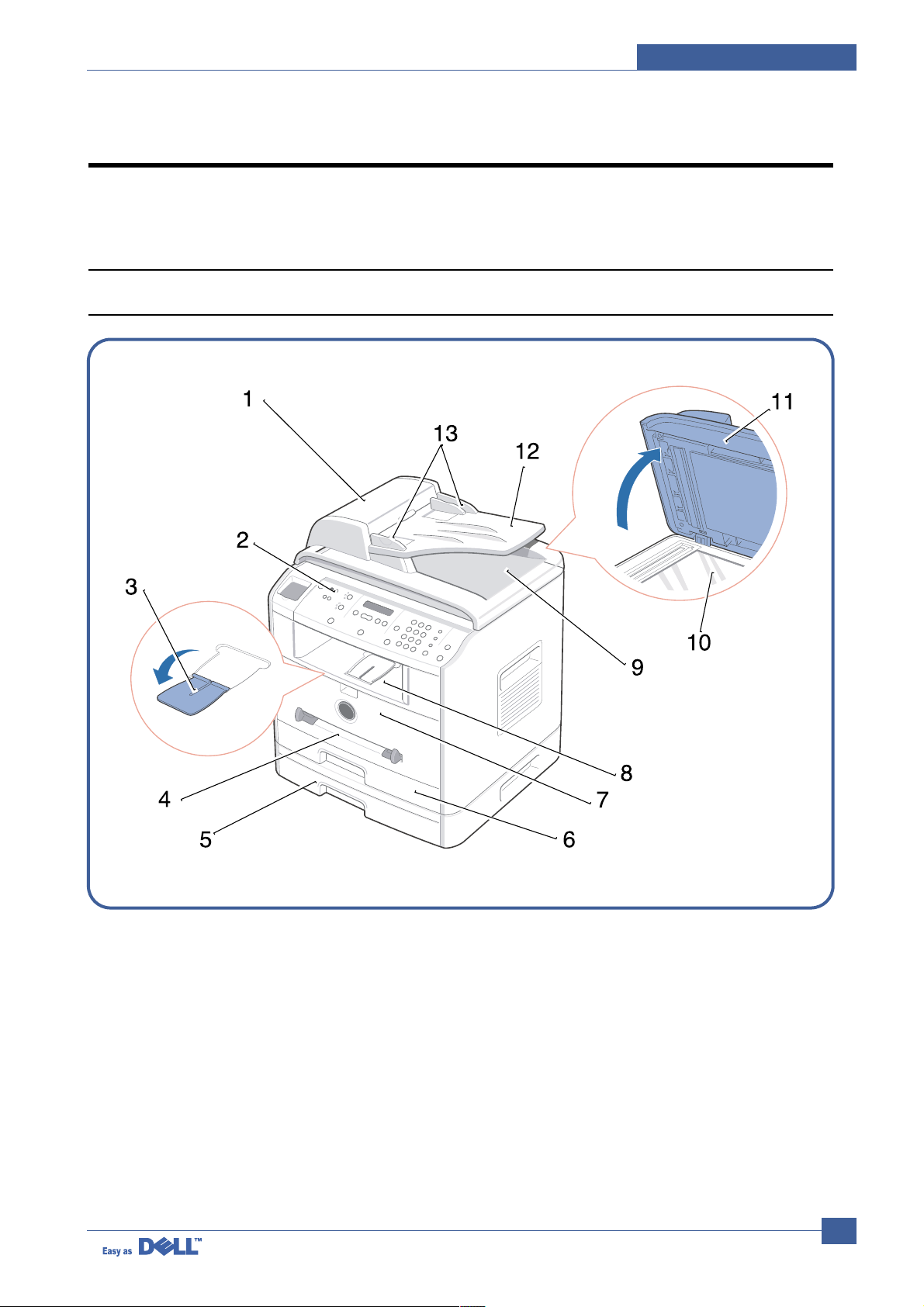
4.1.1 Front View
Page 2
Service Manual
Summary of Product
4-2
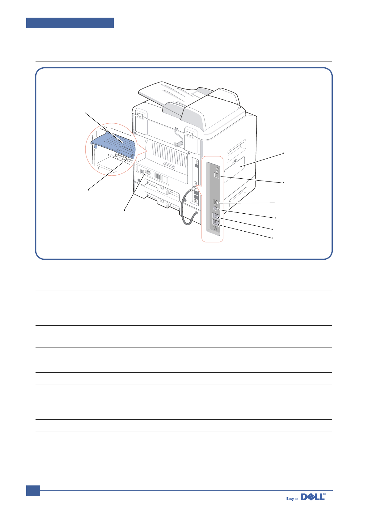
4.1.2 Rear View
15
14
21
22
20
19
17
16
18
# Use the: When you want to:
1 Automatic Document Load the document for copying, scanning, or
Feeder sending faxes.
2 Operator Panel Operate the machine.
3 Paper O utput Keep print media from falling off the front
Extension output tray.
4 Bypass Tray Load print media one sheet at a time.
5 Optional Tray2 Load paper into the optional Tray2.
6 Tray1 Load paper into the standard Tray1.
7 Front Cover Access the toner cartridge.
8 Front Output Tray Hold paper as it exits from the front of the
machine.
9 ADF Output Tray Hold the document as it exits the ADF.
10 Scanner Glass Place a document on the scanner glass for
copying, scanning and sending faxes.
Page 3

Summary of Product
Service Manual
4-3
# Use the: When you want to:
11 Document Cover Open to place a document on the scanner glass.
12 Document Input Tray Load the document for copying, scanning and
sending faxes.
13 Document Guides Ensure proper document feeding.
14 Rear Cover Open to remove the paper jams and use the
rear output slot when you print the documents
from the Bypass tray.
15 Rear Output Slot Hold paper as it exits at the rear of the machine.
16 Power Switch and AC Supply power to the machine.
Power Cord Connector
17 FAX Jack Connect the telephone line to your machine. If
you use this machine in the serial countries,
such as Germany and Sweden, this socket
may be blocked.
18 Phone Jack Connect the telephone or answering machine
to your machine.
19 Optional Tray2 Cable Connect the optional Tray2 to your machine.
Connector
20 USB Cable Connector Insert the USB cable.
21 Network Port Connect the printer to the network port.
22 Control Board Cover Install the optional memory card.
Page 4
Service Manual
Summary of Product
4-4
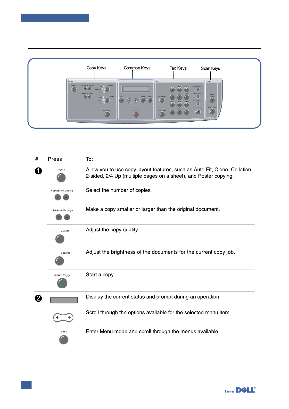
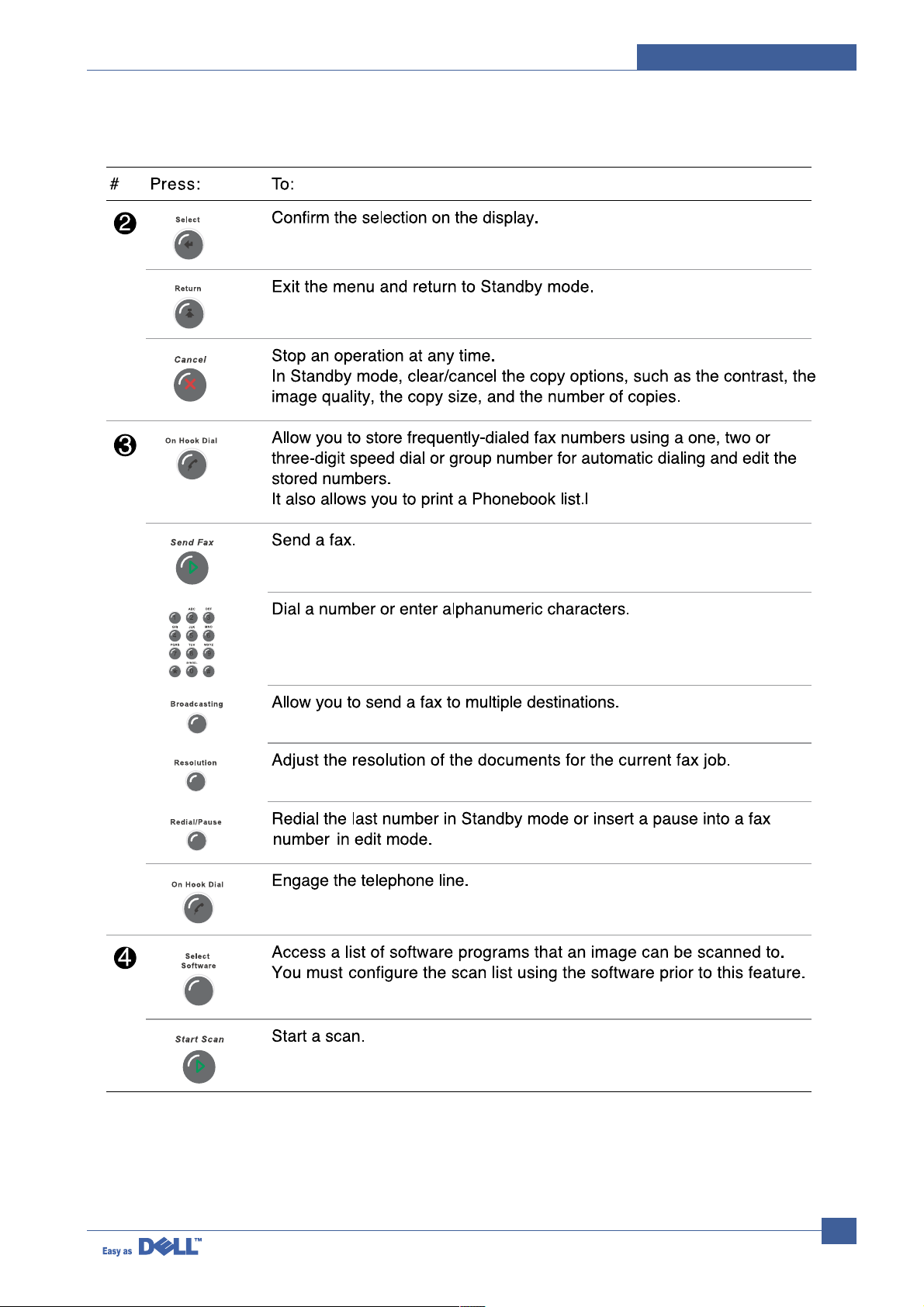
4.1.3 Control Panel
Page 5
Summary of Product
Service Manual
4-5
Page 6

Service Manual
Summary of Product
4-6
4.2 System Layout
4.2.1 Feeding section
There is a universal cassette, which supplies paper to the machine, and the manual feeder, which supplies
paper one by one. The cassette has the friction pad, which separates paper one by one and prevent multisheet feeding. There is a sensor to detect the existence of paper in the cassette.
- Feeding Method: Universal Cassette Type
- Feeding Standard: Center Loading
- Feeding Capacity: Cassette-250 sheets (80g/m2, 20lb paper standard)
Manual 1 sheet (Paper, OHP, Envelope, etc.)
- Paper detecting sensor: Photo sensor
- Paper size sensor: None
4.2.2 Transfer Ass’y
It consists of the PTL (pre-transfer lamp) and the Transfer Roller. The PTL sends a light to the OPC drum,
making the current on the drum surface to low and improves the transfer efficiency.
The transfer roller transfers toner from the OPC drum surface to the paper.
- Life span: 60,000 sheets (in 15~30°C)
4.2.3 Drive Ass’y
- It is motor driven gear unit, which drives the feeding unit, the fusing unit, and the distributing unit
4.2.4 Fuser
- The fuser consists of the Heat Lamp, Heat Roller, Pressure Roller, Thermistor, and Thermostat. It melts
the toner to the paper with pressure and a heat to complete the printing job.
4.2.4.1 Thermostat
The thermostat is a temperature-sensing device, which cuts off the power to prevent overheating or a fire
when the heat lamp or the heat coil of the heat roller becomes too hot.
4.2.4.2 Thermistor
The Thermistor detects the surface temperature of the heat roller and it maintains the regular temperature
of the heat roller by responding to the information of the heat roller’s temperature.
4.2.4.3 Heat Roller
The heat roller transfers the heat from the heat lamp coil to the surface of the paper.
The melted toner cannot stick to the Teflon coated heat roller.
4.2.4.4 Pressure roller
The pressure roller mounted right under the heat roller is made of the silicon resin. The toner fuses onto
the paper when it passes between the heat roller and the pressure roller.
Page 7

Summary of Product
Service Manual
4-7
4.2.4.5 Safety Relevant Facts
• Protecting device when overheating
- 1st protecting device: H/W cuts off when detecting an overheating
- 2nd protecting device: S/W cuts off when detecting an overheating
- 3rd protecting device: Thermostat cuts off the power
• Safety device
- The power to the fuser is cut off when the front cover is open.
- The overheating safety device for the customer safety.
- Maintains the surface temperature of the Fuser Cover below 80°C. Acustomer caution label is
attached on the inside of the rear cover.
4.2.5 Scanner
It reads an image with a photosensitive sensor. It consists of a CCD module, Connection board, ADF board
, AFE (Analog Front End), and Image Processor (Located in CPU), platen glass and ADF.
• CCD Module Specification
1.Resolution: 600dpi/A4
2.Maximum scan wide: 8.5”
3.Color filter: Red, Green, Blue
4.Output channel: 3 channels (R, G, B)
5.Effective pixel: 5,400 pixel *3
6.Voltage: 24V & 5V
7.Pre-heating time: Maximum 30 seconds (70% of light reach to it)
8.The life span of a lamp: 30,000 hours (25oC)
• Image Processor Specification
1.Operating frequency: 66MHz
2.Image sensor interface: 200/300/600 dpi CIS or CCD
3.Line time: Copy, FAX, Binary (Lineart, Halftone) PC Scan: 1.5ms/Line Color PC Scan (Grey, 256
Color, True Color): 4.5ms/Line
4.A/D conversion: 10bit conversion
Page 8

Service Manual
Summary of Product
4-8
4.2.6 LSU (Laser Scanner Unit)
The LSU unit is controlled by the video controller. It scans the video data received from video controller
with laser beam by using a rotating polygon mirror to create the latent image on the OPC drum.
The OPC drum rotates as the same speed as the paper feeding speed. When it hits the corner of the polygon mirror, it generates the /HSYNC signal. The CPU forms the left margin of the image using this signal.
After detecting the /HS YNC signal, the image data is sent to the LSU to arrange the its left margin on the
paper.
Each surface of the polygon mirror provides one line for scanning.
Page 9

Summary of Product
Service Manual
4-9
4.2.7 Toner Cartridge
By using the xerographic process, it creates a visual image. The Toner Cartridge contains the OPC Drum,
developer and toner components in one unit. The OPC unit contains the OPC drum and charging roller.
The developer unit contains toner, toner cartridge, supply roller, developing roller, and blade (Doctor blade)
- Developing Method: Non magnetic 1 element contacting method
- Toner: Non magnetic 1 element shatter type toner
- The life span of toner: 3,000 sheets (ISO Pattern)
- Toner remaining amount detecting sensor: None
- OPC Cleaning: Collect the toner by using electric static + FILM OPC
- Management of disusable toner: Collect the toner by using electric static (Clenerless Type- No
disusable toner)
- OPC Drum protecting Shutter: None
- Classifying device for toner cartridge: ID is classified by interruption of the frame channel.
Page 10

Service Manual
Summary of Product
4-10
4.3 Main PBA
It is the functional center of the product. It controls the basic machine operations including the fax, scan,
printer operations, sensor detection and power levels.
1
2
3
4
5 23
6
7
9
10
11
12
13
14
15
8
7
716
717
724
718
719
720
721
722
Page 11

Summary of Product
Service Manual
4-11
MOTOR DRIVER(TEA3718SFP) U6
MOTOR DRIVER(TEA3718SFP) U12
QUAD 2-INPUT OR GATE(74VHX32) U10
QUAD 2-INPUT OR GATE(74VHX32) U7
QUAD 2-INPUT OR GATE(74VHX32) U70
VEDIC X-TAL(19.6MHz) OSC2
PROCESSOR ASIC(SPGPM) U33
CPU X-TAL(12MHz) OSC10
USB 2.0(NET2272) U48
VARTA(3.6V BATT)
RELAY(HRSIKH) RE1
SDRAM(K4S281632E) U43
SDRAM(K4S281632E) U44
MODEM(CXB2500-11) U52
MOTOR DRIVER(A3977SLP) U50
FLASH MEMORY PCL-HIGH(29LV160DB) U27
FLASH MEMORY PS3-HIGH(29LV160DB) U19
FLASH MEMORY PCL6-LOW(29LV160DB) U28
FLASH MEMORY PS3-LOW(29LV160DB) U20
FLASH MEMORY COED-LOW(29LV160DB) U15
IMAGE PROCESSOR(CIP4E) U11
SRAM(K6R1016VID) U9
A/D CONVERTER(AFE-CIP4) U5
FLASH MEMORY CODE-HIGH(29LV160DB) U14
1
2
3
4
5
6
7
8
9
10
11
12
13
14
15
16
17
18
19
20
21
22
23
24
Page 12

Service Manual
Summary of Product
4-12
4.3.1 ASIC
Samsung’s S3C46Q0X 16/32-bit RISC micro controller is designed to provide a cost-effective, low power,
small die size and high performance micro-controller solution for MFP.
The S3C46Q0X is developed using ARM7TDMI core, 0.18(m CMOS standard cell, and memory cell.
• Main function block
• 1.8V internal, 3.3V external (I/O boundary) microprocessor with 4KByte Cache
• Image Processor
• On-chip clock generator with PLL
• Memory & External Bank Control
• DMA Control (5-channel)
• Interrupt Control
• 2-port USB Host /1- port USB Device (ver 1.1) Interface Control
• Parallel Port Interface Control
• UART (2 Channel)
• Synchronous Serial Interface Control
• Timer (4 Channel)
• Watch Dog Timer
• Power control: Normal, Slow, Idle, Stop and SL_IDLE mode
• A/D Converter (10-bit, 2 Channel)
• General I/O Port Control
• Print Head Control
• Carrier Motor Control
• Paper Motor Control
• Tone Generator
• RTC with calendar function
• S/W Assistant function( Rotator )
4.3.2 Flash Memory
It stores the system program and downloads the system program through the PC interface.
• Capacity : 0.5 M Byte
• Access Time : 70 nsec
4.3.3 SDRAM
It is used as a buffer, system working memory area, etc. while printing.
• Access Time : 60 nsec
Page 13

Summary of Product
Service Manual
4-13
4.3.4 Sensor input circuit
1) Paper Empty Sensor
The Paper empty sensor (Photo Interrupter) on the engine board informs the CPU as to whether
the cassette is empty or not with operation of the actuator.
When the cassette is empty, it detects the fact by reading the D0 Bit of CPU. It highlights this by
selecting the second LED(yellow) among the panel LEDs.
2) MP Sensing
The MP Sensor (Photo Interrupter) on the engine board informs the CPU as to whether the MP is
empty or not. It reads the D0 Bit of CPU to recognize paper in MP, and the paper is fed from MP if
present.
3) Paper Feeding
When paper passes the actuator (feed sensor part), it detects the signal of Photo interrupter,
informs the paper feeding state to the CPU, and then sends the image data after a certain time. If it
doesn't detect the feed sensor within 1 sec. after paper is fed, paper Jam0 occurs (Red and Yellow
will be turned on among the OP panel LEDs), and whether the developer is inserted or not is
detected with the same principle. After the developer is mounted, the actuator is operated. The signal from the photo interrupter is detected when it is passing the actuator of the sensor part. That
process is called developer ID sensing.
4) Paper Exit Sensing
The system detects the paper going out of the set with the exit sensor assembled to the actuator
attached to the frame. Paper detects the on/off time of exit sensor, and the normal operation or jam
information is passed to the CPU.
The paper JAM2 is informed.
5) Cover Open Sensing
The Cover open sensor is located on the front cover. After the front cover is opened, +24V (DC fan,
solenoid, main motor, polygon motor part of LSU, HVPS), which is supplied to the each unit, is cut off.
The cover-open sensing is operated by the D0 bit of CPU, and the developer ID sensing is operated.
6) DC FAN / SOLENOID Driving
It is driven by transistor and controlled by D6 bit of CPU.
When it is high, the fan is driven by turning on the TR, and it is off when the sleep mode is selected. There are two solenoids, and they are driven by the paper pick-up and MP signal. Its drive time
is 300ms. The diode protects the driving TR from the noise pulse, which is emitted when the solenoid is de-energizing.
7) Motor Driving
The motor driving circuit is formed when the Driver IC is selected. The A3977 (Motor driver IC) is
used in this case. The resistance Rs value of sensing and the voltage value of the V reference can
be changed by the motor driving voltage value.
Page 14

Service Manual
Summary of Product
4-14
4.4 SMPS & HVPS
The SMPS supplies the DC power to the system.
It takes 110V/220V and outputs the 5V, 12V and 24V to supply the power to the main board and ADF
board.
The HVPS part creates the high voltage of THV/MHV/Supply/Dev and supplies it to the developer part for
making the best condition to display the image. The HVPS part takes the 24V and outputs the high voltage
for THV/MHV/BIAS, and the outputted high voltage is supplied to the toner, OPC cartridge, and transfer
roller.
Page 15

Summary of Product
Service Manual
4-15
4.4.1 HVPS(High Voltage Power Supply)
1) Transfer High Voltage (THV+)
- Function : Voltage to transfer developed toner on OPC drum to a paper.
- Output voltage : +1300V DC±20V
- Error : If THV (+) doesn't output, a ghost status (same character is printed after one cycle (76mm)
of OPC) with a low density occurs due to a toner on OPC drum cannot normally transfer to
a paper.
2) Charge Voltage (MHV)
- Function : It is a voltage to charge entire surface of OPC with -900V ~ -1000V.
- Output voltage : -1550V DC ± 50V
- Error : If MHV doesn't output, a black paper is printed out because toner on developing roller
moves to OPC drum due to the surface of OPC not being charged.
3)Cleaning Voltage (THV-)
- Function : It removes a dirty on a surface by sending a minus toner in a transfer roller to an OPC
drum to recover toners.
- Output Voltage : +1000V/-1200V
- Error : Toner contamination occurs at the backside of a printed-paper.
4) Developing Voltage (DEV)
- Function: It is a voltage to develop a toner with using a difference of electronic potential on an
exposed part by LSU (Laser Scanning Unit).
* Generally, the electronic potential of exposed OPC is -180V and exposed developer is -350V
when printing, so toner with minus (-) is developed on an exposed part.
- Output voltage: -430V DC ± 20V
- Error: 1. If DEV is GND, a density is going significantly down.
2. If DEV is floating due to instable contacting point of terminal, and etc., a density is significantly going up.
5) Supply Voltage (SUP)
- Function: It is a voltage to supply toner to a developing roller.
- Output voltage: : -580V DC ± 50V (Use ZENER, DEV Gear)
- Error: 1. If SUP is GND, a density is dramatically going down.
2. If SUP is floating due to instable contacting point of terminal, and etc., a density is significantly going down as much as it cannot be recognized with eyes.
Page 16

Service Manual
Summary of Product
4-16
4.4.2 SMPS(Switching Mode Power Supply)
It is the power source of entire system. It is assembled by an independent module, so it is possible to use for
common use. It is mounted at the bottom of the set.
It is consisted of the SMPS part, which supplies the DC power for driving the system, and the AC heater control
part, which supplies the power to fuser. SMPS has two output channels. Which are +5V and +24V.
1) AC Input
> Input Rated Voltage : AC 220V ~ 240V AC 120V / AC 220V(EXP version)
> Input Voltage fluctuating range : AC 198V ~ 264V AC 90V ~ 135V / AC 198V ~ 264V
> Rated Frequency : 50/60 Hz
> Frequency Fluctuating range : 47 ~ 63 Hz
> Input Current : Under 5.0Arms / 2.5Arms (But, the status when lamp is off or rated voltage is
inputted/outputted )
2) Rated Output Power
3) Consumption Power
4) Length of Power Cord :
1830 ± 50mm
5) Power Switch :
Use
NO ITEM CH2 CH3 Remark
1 CHANNEL NAME +5V +24.0V
2 CONNECTOR PIN CON 3 CON 3
5V PIN: 8 24V PIN:11,12,13
GND PIN: 7 GND PIN:9,10
3 Rated Output +5V & 5% +24V & 10%
(4.75 % 5.25V) (21.6 % 26.4V)
4 Max. Output voltage 0.14 A 2.0 A
5 Peak Loading voltage 0.14 A 2.5 A 1ms
6 RIPPLE NOISE 100mVp-p Under 500mVp-p
Voltage
7 Maximum output 0.35W 48W
8 Peak output 0.7W 60W 1ms
9 Protection for loading -
shortage and
overflowing current
NO ITEM CH2 (+5V) CH3 (+24V) Remark
1 Stand-By 0.07A 0.4 A AVG:55 Wh
2 PRINTING 0.14A 2.0 A AVG 350 Wh
3 Sleep-Mode 0.01A 0.4A AVG : 20 Wh
Page 17

Summary of Product
Service Manual
4-17
6) Feature
- Insulating resistance : over 50MΩ (at DC500V)
- Insulating revisiting pressure : Must be no problem within 1min. (at 1500Vzc, 10mA)
- Leaking voltage : under 3.5mA
- Running voltage : under 40A peak (at 25°c, Cold start) Under 60A peak (in other conditions)
- Rising Time : Within 2Sec
- Falling Time : Over 20ms
- Surge : Ring Wave 6KV-500A (Normal, Common)
7) Environment Condition
- Operating temperature range : 0°c ~ 40°c
- Maintaining temperature range : -25°c ~ 85°c
- Maintaining humid range : 30% ~ 90% RH
- Operating atmospheric pressure range : 1
8) EMI Requirement :
CISPR ,FCC, CE, MIC, C-Tick,
9) Safety Requirement
- IEC950, C-UL, TUV,Semko,iK,CB, CCC, EPA,
4.4.3 Fuser AC Power Control
Fuser (HEAT LAMP) gets heat from AC power. The AC power controls the switch with the Triac, a semiconductor switch. The 'On/Off control' is operated when the gate of the Triac is turned on/off by Photo triac
(insulting part).
In the other words, the AC control part is passive circuit, so it turns the heater on/off with taking signal from
engine control part.
When the 'HEATER ON' signal is turned on at engine, the LED of PC1 (Photo Triac) takes the voltage and
flashes. From the blinking light, the Triac part (light receiving part) takes the voltage, and the voltage is supplied to the gate of Triac and flows into the Triac. As a result, the AC current flows in the heat lamp, and
heat is occurred.
On the other hand, when the signal is off, the PC1 is off, the voltage is cut off at the gate of Triac, the Triac
becomes off, and then the heat lamp is turned off.
1) Triac (THY1) feature
- 12A,600V SWITCHING
2) Phototriac Coupler (PC3)
- Turn On If Current : 15mA~ 50mA(Design: 16mA)
- High Repetive Peak Off State Voltage : Min 600V
Page 18

Service Manual
Summary of Product
4-18
4.5 Engine F/W
4.5.1 Feeding
If feeding from a cassette, the drive of the pickup roller is controlled by controlling the solenoid. The on/off
of the solenoid is controlled by controlling the general output port or the external output port. If feeding
from a manual feeder, insert the paper according to the operation of the manual sensor, and by driving the
main motor, insert the paper in front of the feed sensor. While paper moves, occurrence of jam is judged
as below. (Refer to the [6.2 Paper Transfer rout])
4.5.1.1 Jam 0
• After picking up, paper cannot entered due to paper didn’t feed.
• After picking up, paper entered but it cannot reach to the feed sensor in certain time due to slip, etc.
• After picking up, if the feed sensor is not on, repack up. After repacking up, if the feed sensor is not on
after certain time, it is Jam 0.
- It is a status that the leading edge of the paper doesn’t pass the feed sensor.
• Even though the paper reaches the feed sensor, the feed sensor doesn’t turn on.
- It is a status that the leading edge of the paper already passes the feed sensor.
4.5.1.2 Jam 1
• After the leading edge of the paper passes the feed sensor, the trailing edge of the paper cannot pass the
feed sensor after certain time. (The feed sensor cannot be Off)
• After the leading edge of the paper passes the feed sensor, the paper cannot pass the exit sensor after
certain time. (The exit sensor cannot be On)
- The paper exists between the feed sensor and the exit sensor.
4.5.1.3 Jam 2
• After the trailing edge of the paper passes the feed sensor, the paper cannot pass the exit sensor after
certain time.
4.5.2 Drive
By gearing, the main motor drives the rollers such as feeding roller, developing roller, fuser roller, and distributing roller. The step motor is controlled for the sections, acceleration section and fixed speed section.
In the initial stage of the motor run, appoint the acceleration section to prevent the isolation of the motor. It
is controlled by the A3977 motor driver IC. The step signal and the enable signal are sent to make the
phase for driving the motor in CPU.
4.5.3 Transfer
The charging voltage, developing voltage and the transfer voltage are controller by PWM (Pulse Width
Modulation). The each output voltage is changeable due to the PWM duty. The transfer voltage admitted
when the paper passes the transfer roller is decided by environment recognition. The resistance value of
the transfer roller is changed due to the surrounding environment or the environment of the set, and the
voltage value, which changes due to the environments, is changed through AD converter. The voltage
value for impressing to the transfer roller is decided by the changed value.
Page 19

Summary of Product
Service Manual
4-19
4.5.4 Fusing
The temperature change of the heat roller’s surface is changed to the resistance value through the thermistor. By converting the voltage value to a digital value, through the AD converter, the temperature is decided.
The AC power is controlled by comparing the target temperature to the value from the thermistor. If the value
from the thermistor is out of the controlling range while controlling the fusing, the error stated in the table
occurs.
4.5.4.1 Error Type
4.5.5 LSU
The LSU is consists of the LD (Laser Diode) and the polygon motor control. When the printing signal occurs,
it turns the LD and drives the polygon motor. When the receiving light part detects the beam, Hsync occurs.
When the polygon motor speed becomes normal, LReady occurs. If the two conditions are satisfied, the status bit of the LSU controller register becomes 1, the LSU is ready. If the two conditions are not satisfied, the
error shown in below occurs.
Error Description
Open heat error When warming up, it has been lower than 68 °C over 25 sec
Lower heat error • Standby:
It has been lower than 100°C over 25 sec
• Printing:
- 2 consecutive pages: it has been lower than 145°C over 5 sec
- 3 consecutive page; it has been 40°C lower than the fixed fusing temperature over 4 seconds.
Over heat error It have been higher than 220°C over 3 seconds
Error Description
Polygon motor error When the polygon motor’s speed doesn’t become normal
Hsync error The polygon motor’s speed is normal, but the Hsync signal is not created.
Page 20

Service Manual
Summary of Product
4-20
4.6 LIU PBA
LIU board is a Line interface unit, and it is a circuit for interfacing a telephone line with a modem. The circuit is consisted of matching transfer to conform to impedance of a receiving telephone line and a circuit to conform to impedance of a
modem.
Also, there is a ring detect circuit to detect a ring signal from a switchboard and a surge absorber to protect it from an
external high voltage supply applied to a line input unit.
4.7 OPE PBA
OPE board is consists of various function keys and LCD to display an operation of key. MICOM creates
a circuit with using HT48R50 MICOM of HOLTEC CO. and applies LED and LCD. Acommunication
method with a CPU of a main board is UART, and related signals are /Reset, TXD, and RXD.
 Loading...