

Page 1
Troubleshooting
Service Manual
7-1
7
7
7. Troubleshooting
7.1 Paper Feeding Problems
7.1.1 Wrong Print Position
• Description Printing begins when the paper is in the wrong position.
Check and Cause Solution
A defective feed sensor actuator can cause incorrect timing.
Replace the defective actuator
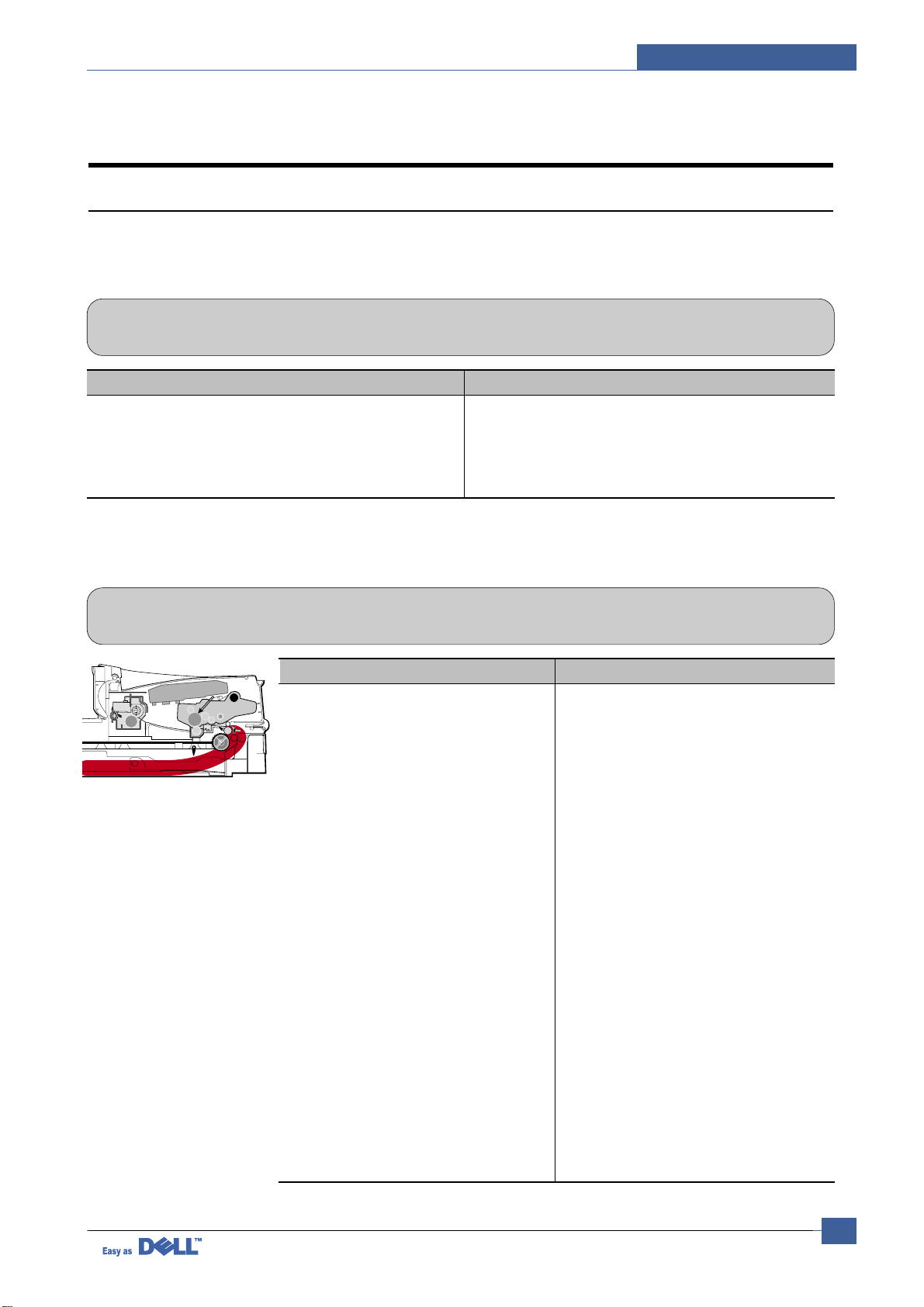
7.1.2 JAM 0
• Description
1. Paper has not exited from the cassette.
2. Jam-0 occurs if the paper feeds into the printer.
PTL
P
I
C
K
/
R
PR
CR
DR
SR
TR FR
Empty Sensor
OPC
L S U
Fuser
Toner Cartridge
EXIT
Sensor
Feed
Sensor
MP Sensor
Check and Cause Solution
1. Check the Solenoid by using Engine
Test Mode : Diagnostic Mode code 0
2. Check if the pad is loose due to bad
sealing of the side-pad.
3. Check the surface of the roller-pickup for foreign matter.
4. If continuous clusters occur, check
whether the assembly slot between
shaft-pickup and housing-pickup
become open or is broken away.
5. If the paper feeds into the printer
rand Jam 0 occurs, perform DCU to
check feed-sensor of the engine
board.
1. Replace the solenoid.
2. Replace the side-pad Assembly Lor
R, if necessary.
3. Clean with soft cloth dampened with
IPA(Isopropyl Alcohol) or water.
4. Replace the Housing-Pickup and/or
Shaft-Pickup.
Page 2
Service Manual
Troubleshooting
7-2
7.1.4 JAM 2
• Description
1. Recording paper is jammed in front of or inside the fuser.
2. Recording paper is stuck in the discharge roller and in the fuser just after passing through the
Actuator-Feed.
PTL
P
I
C
K
/
R
PR
CR
DR
SR
TR FR
Empty Sensor
OPC
L S U
Fuser
Toner Cartridge
EXIT
Sensor
Feed
Sensor
MP Sensor
Check and Cause Solution
1. If the paper is completely fed out of
the printer, but Jam 2 occurs
: Exit sensor is defective.
• After the paper is completely dis-
charged, actuator Exit should return
to the original position to shut off the
photo-sensor. Sometimes it takes
longer than it should and does not
return.
2. If the paper is rolled in the Fuser Roller:
• This occurs when a Guide claw is
broken away or transformed.
• It occurs when the Guide slaw spring
is broken away or transformed.
• It occurs when the Heat-Roller or
Pressure-Roller is seriously contaminated with toner powder.
3. Paper is accordion jammed in fuser.
1. Check if the exit sensor actuator is
defective.
• Check if the actuator exit is deformed
(Check if the lever part is deformed
in shape).
• Check whether burrs occur in the
assembly part of the actuator exit or
not and if the actuator is smoothly
operated.
• Check if foreign matters and wire get
caught in the actuator exit's operation.
2. If the paper is stuck in the fuser : dis-
assemble the fuser and remove the
jammed paper, and clean the surface
of the pressure roller with dry gauze.
3. Remove the jammed paper after disas-
sembling the fuser : Clean the surface
of the pressure roller with dry gauze.
• Remove the toner particles stained
on the rib.
• Check the assemblage and perfor-
mance of the exit.
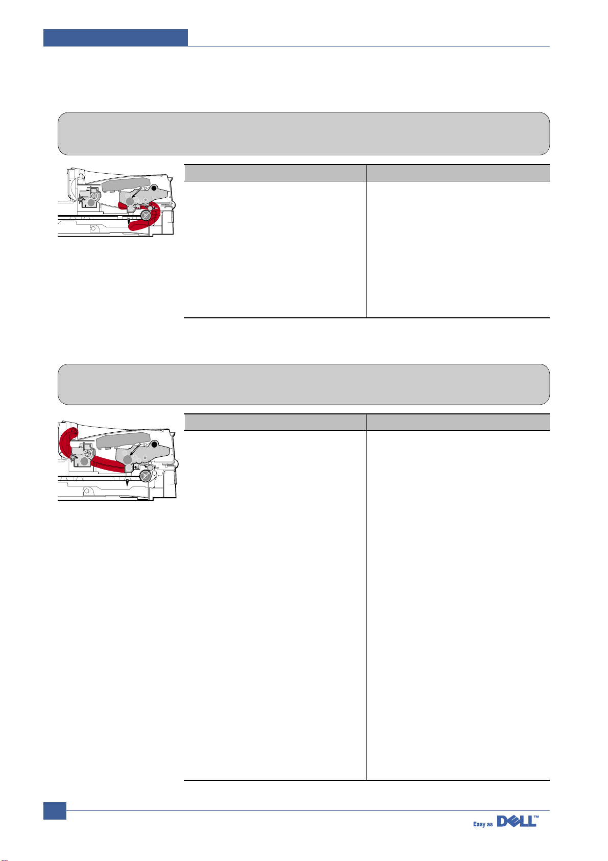
7.1.3 JAM 1
• Description
1. Recording paper is jammed in front of or inside the fuser.
2. Recording paper is stuck in the discharge roller and in the fuser just after passing through the
Actuator-Feed.
PTL
P
I
C
K
/
R
PR
CR
DR
SR
TR FR
Empty Sensor
OPC
L S U
Fuser
Toner Cartridge
EXIT
Sensor
Feed
Sensor
MP Sensor
Check and Cause Solution
1. If the recording paper is jammed in
front of or inside the fuser.
2. If the recording paper is stuck in the
discharge roller and the fuser just
after passing through the ActuatorFeed, Feed Actuator may be defective.
1. Replace the SMPS.
2. Reassemble the Actuator-Feed and
Spring-Actuator if the return is bad.
Page 3

Troubleshooting
Service Manual
7-3
7.1.5 Multi-Feeding
• Description Multiple sheets of paper are fed at once.
Check and Cause Solution
1. Solenoid malfunction(the solenoid does not work
properly): Perform Engine Test Mode : Diagnostic
Mode code 0.
2. Friction-Pad is contaminated with foreign matter.(oil..)
3. The face of paper is blended.
1. Replace the solenoid if necessary.
2. Clean the friction-pad with soft cloth dampened with
IP A(Isopropyl Alcohol).
3. Use the smooth paper.
7.1.6 Paper rolled in the fuser
• Description If contaminated at intervals of 57mm on the back of a paper.
Check and Cause Solution
1. Contamination of the pressure roller.
(Background, Hot off set)
1. Disassemble the fuser, clean the area between the
Heat-roller and Thermistor and remove the foreign
matter off of the pressure roller.
2. If background appears badly in the printing, fix it by
referring to the solutions for background.
(See 4.5.8 Background)
Page 4

Service Manual
Troubleshooting
7-4
7.1.7 Paper rolled in the OPC
• Description Paper is rolled up in the OPC.
Check and Cause Solution
1. Paper is too thin.
2. The face of paper is curled.
1. Recommend to use normal paper thickness.
2. How to remove the rolled paper in the OPC.
• Remove the paper while turning the OPC against
the ongoing direction.
• Clean fingerprints on the OPC softly with soft
cloth dampened with IPA(Isopropyl Alcohol) or tissue.
7.1.8 Defective ADF
• Description
ADF (Automatic document Feeder) is not properly operated.
Check and Cause Solution
1. Check if ADF rubber and HOLDER rubber are damaged.
2. Check if the document sensors of ADF Ass’y
(3 paper sensors) are normal.
1. Replace the contaminated or damaged part.
2. If you cannot confirm the damaged part with the
naked eye, try to replace the ADF Ass’y.
Page 5

Troubleshooting
Service Manual
7-5
7.2. Printing Problems (malfunction)
7.2.1 Defective Operation (LCD WINDOW ) Display
• Description
Strange characters are displayed on the OPE Panel and buttons are not operated.
Check and Cause Solution
1. Clear the memory.(see page 6.5.3)
2. Check if OPE HARNESS is connected to the Connection
B'd correctly.
1. Try again after clearing the memory.
2. After confirming that OPE HARNESS is connected to
the Connection B'd correctly, if it is so, then replace
the OPE Ass’y and Main Board in sequence.
7.2.2 Defective LCD Operation
• Description
Defective LCD Operation
Check and Cause Solution
1. Clear the memory. (See page 6.5.3).
2. Confirm to catch a click sound, while a key on the OPE
panel is pressed on.
1. The key is wrong itself or wrongly assembled.
2. Even after the key has been replaced, it is still wrong,
try to replace the OPE Ass’y and the Main B'd in
sequence.
Page 6

Service Manual
Troubleshooting
7-6
7.2.3 Not functioning of the fuser gear due to melting away
• Description
The Motor breaks away from its place due to gear melting away.
Check and Cause Solution
1. Check the Heat Lamp. 1. Replace the Fuser.
2. Replace the Main PBA.
3. Replace the SMPS.
7.2.4 Paper Empty
• Description
The paper lamp on the operator panel is on even when paper is loaded in the cassette.
Check and Cause Solution
1. Bending or deformation of the actuator of the paper sensor.
2. The function of the Main PBA is defective Perform
Engine Test Mode : Perform Engine Test Mode diagnostic code 2.
1. Replace the defective actuator.
2. Replace the Main PBA.
7.2.5 Paper Empty without indication
• Description
The paper lamp on the operator panel does not come on when the paper cassette is empty.
Check and Cause Solution
1. Bending or deformation of the actuator of the paper sensor.
2. The function of the Main PBAis defective Perform.
1. Replace the defective actuator.
2. Replace the Main PBA.
Page 7

Troubleshooting
Service Manual
7-7
7.2.6 Door Open
• Description
The ERROR lamp is on even when the print Door is closed.
Check and Cause Solution
1. The hook lever in the Front Cover may be defective.
2. Check the Connector(CN1) and Circuit of the Cover
Switch department in the Main PBA.
1. Replace the hook lever, if defective.
2. Check the insertion of the Door Open S/W Connect.
3. Replace the Main PBA or Door Open S/W.
7.2.7 No Beep on when the Door is open
• Description
The ERROR lamp does not come on even when the printer Door is open.
Check and Cause Solution
Check the Connector(CN1) and Circuit of the Cover Switch
department in the Main PBA.
1. Check the insertion of the Door S/W Connect.
2. Replace the Main PBA or Door Open S/W.
Page 8

Service Manual
Troubleshooting
7-8
7.2.8 Defective Motor operation
• Description
Main Motor is not driving when printing, and paper does not feed into the printer, resulting 'Jam 0'.
Check and Cause Solution
1. Motor harness or sub PCB may be defective.
2. Perform Engine Test Mode diagnostic code 0 and Check
the Motor operation.
1. Check the Motor harness, replace it, if defective.
2. Replace the SMPS, if necessary.
7.2.9 No Power
• Description
When system power is turned on, all lamps on the operator panel do not come on.
Check and Cause Solution
1. Check if the power input and SMPS output are normal.
2. Check for defective of LCD-Panel on the front-cover if the
LCD of Panel does not appear after normal warming-up.
1. Replace the power supply cord or SMPS.
2. Replace the control board.
3. Replace the LCD-panel.
Page 9

Troubleshooting
Service Manual
7-9
7.2.10 Vertical Line Getting Curved
• Description
When printing, vertical line gets curved.
Check and Cause Solution
1. If the supply of +24v is unstable in the Main Control board
linking with LSU, check drive by Engine Test Mode :
Diagnostic Code 1 LSU Motor on.
1. Replace LSU.
2. Replace the Main Control board.
Page 10

Service Manual
Troubleshooting
7-10
7.3.1 Vertical Black Line and Band
• Description
1. Straight thin black vertical line occurs in the printing.
2. Dark black vertical band occur in the printing.
Digital Printer
Digital Printer
Digital Printer
Digital Printer
Digital Printer
Check and Cause Solution
1. Damaged develop roller in the Developer.
Deformed Doctor-blade.
2. Scratched surface of the charge roller in
the developer.
3. Partial depression or deformation on the
surface of the transfer roller.
1. If causes 1 and 2 occur in the developer
cartridge, replace the developer and try to
print out.
2. Replace the transfer roller if occurred as
No. 3.
7.3.2 Vertical White Line
• Description White vertical voids in the image.
Digital Printer
Digital Printer
Digital Printer
Digital Printer
Digital Printer
Check and Cause Solution
1. Foreign matter stuck onto the window of
internal lenses of LSU mirror.
2. Foreign matter or toner particles between
the developer roller and blade.
(In case the life of the developer has
been expired, white lines or light image
occur in front of the image.)
3. It may occur when a Burr and foreign
substances are on the window of the
developer frame.
4. If the fuser is defective, voids occur periodically at the top of a black image.
1. Foreign matter stuck onto the window :
Clean the LSU window with recommended cleaner(IPA) Clean the window with a
clean cotton swab.
2. Foreign matter in the LSU : Open the
cover of LSU and clean with a cotton
swab on the surface of the reflex mirror.
3. No 3. : Remove the foreign matter and
burr of the exposure window.
(Developer cartridge)
4. No. 4. : Open the front cover and check
ribs that corresponds to the position of
the voids. Remove if found.
5. If the problems are not solved, replace
the developer cartridge.
7.3 Printing Quality Problems
Page 11

Troubleshooting
Service Manual
7-11
7.3.3 Horizontal Black Band
• Description
1. Dark or blurry horizontal stripes occur in the printing periodically.
(They may not occur periodically.)
Digital Printer
Digital Printer
Digital Printer
Digital Printer
Digital Printer
Check and Cause Solution
1. Bad contacts of the voltage terminals to
developer.
2. The rollers of developer may be stained.
Charge roller = 37.7 mm
Supply roller = 37 mm
Develop roller = 35.3 mm
Transfer roller = 45.3 mm
1. Clean each voltage terminal of the Charge,
Supply, Develop and Transfer roller.
(remove the toner particles and paper particles)
2. Clean the right Gear that has a relatively
small gap of the teeth in the OPC.
3. If the malfunction persists, replace the
developer.
7.3.4 Black/White Spot
• Description
1. Dark or blurry black spots occur periodically in the printing.
2. White spots occur periodically in the printing.
Digital Printer
Digital Printer
Digital Printer
Digital Printer
Digital Printer
Check and Cause Solution
1. If dark or blurry black spots occur
periodically, the rollers in the Developer
may be contaminated with foreign matter
or paper particles.
( Charge roller : 37.7 mm interval
OPC drum : 75.5 mm interval)
2. If faded areas or voids occur in a black
image at intervals of 75.5 mm, or black
spots occur elsewhere, the OPC drum
surface is damaged.
3. If a black image is partially broken, the
transfer voltage is abnormal or the transfer roller's life has expired.
1. Run OPC cleaning Mode Print and run the
Self-test 2 or 3 times.
2. In case of 75.5 mm interval unremovable in
1, cleanly remove foreign substances stuck
on the OPC location equivalent to black
spots and white spots with a dry duster.
3. The transfer roller guarantees 60,000
sheets printing. If the roller's life is expired,
replace it.
4. In case of 37.7 mm interval unremovable in
1, take measures as to replace the developer cartridge and try to print out.
5. Clean the inside of the set against the paper
particles and foreign matter in order not to
cause the trouble.
Page 12

Service Manual
Troubleshooting
7-12
7.3.5 Light Image
• Description The printed image is light, with no ghost.
Digital Printer
Digital Printer
Digital Printer
Digital Printer
Digital Printer
Check and Cause Solution
1. Develop roller is stained when the toner
of developer cartridge is almost consumed.
2. Ambient temperature is below than 10°C.
3. Bad contact caused by the toner stains
between the high voltage terminal in the
HVPS and the one in the set.
4. Abnormal output from the HVPS.
(Run self-test and check 1~4)
1. Check if the Toner Save Mode is off.
2. No 1 : R
eplace the developer cartridge and
try to print out.
3. No 2 : Wait 30 minutes after printer is powered on before you start printing.
4. No3 : Clean up the contaminated area by
the toner.
5. Replace the HVPS if the problems are not
solved by the above four directions.
7.3.6 Dark Image or a Black
• Description The printed image is dark.
Digital Printer
Digital Printer
Digital Printer
Digital Printer
Digital Printer
Check and Cause Solution
1. No charge voltage in the Main PBA.
( Perform Engine Test Mode : Diagnostic
code 4 HVPS check.)
2. Charge voltage is not turned on due to
the bad contacts between power supply
in the side of the Developer and charge
terminal of HVPS.
1. Clean the high voltage charge terminal.
2. Check the state of the connector which
connects the engine board and HVPS.
3. If steps 1 and 2 above did not correct the
problem, replace the HVPS .
Page 13

Troubleshooting
Service Manual
7-13
7.3.7 Uneven Density
• Description Print density is uneven between left and right.
Check and Cause Solution
1. The pressure force on the left and right
springs of the transfer roller is not even,
the springs are damaged, the transfer
roller is improperly installed, or the transfer roller bushing or holder is damaged.
2. The life of the Developer has expired.
3. The toner level is not even on the developer roller due to the bad blade.
1. Replace both the left and right Spring
Holder.
2. Problem with the toner cartridge, replace
the toner cartridge and try to print out.
7.3.8 Background
• Description Light dark background appears in whole area of the printing.
Digital Printer
Digital Printer
Digital Printer
Digital Printer
Digital Printer
Check and Cause Solution
1. Recycled recording paper has been
used.
2. The life of the Developer has expired.
3. The up-to-down movement of the transfer roller is swift?
4. The HVPS is normal?
(Perform Engine Test Mode diagnostic
code 4)
1. Quality is not guaranteed when using recycled paper.
2. Replace the toner cartridge.
3. Clean the busing on the transfer roller.
4. Replace the HVPS.
Page 14

Service Manual
Troubleshooting
7-14
7.3.9 Ghost (1)
• Description Ghost occurs at 75.5 mm intervals of the OPC drum in the whole printing.
Digital Printer
Digital Printer
Digital Printer
Digital Printer
Digital Printer
Digital Printer
75.5 mm
Check and Cause Solution
1. Bad contacts caused by contamination
from toner particles between high voltage
terminal in the main body and the electrode of the Developer.
2. Bad contacts caused by contamination
from toner particles between high voltage
terminal in the main body and the one in
the HVPS board.
3. The life of developer is expired.
4. Transfer roller lifetime(60,000 sheets) has
expired.
5. Abnormal low temperature(below 10°C).
6. Damaged cleaning blade in the developer .
1. Clean the contaminated terminals.
2. Problem in the toner cartridge, replace the
toner cartridge and try to print out.
3. Replace the engine board if not solved by
the above directions 1-2.
4. If not solved by the direction 3, check the
transfer roller lifetime and replace it.
5. Wait about 1 hour after power on before
using printer.
6. Problem in the toner cartridge, replace the
toner cartridge and try to print out.
7.3.10 Ghost (2)
• Description
Ghost occurs at 75 mm intervals of the OPC drum in the whole printing.
(When printing on card stock or transparencies using manual feeder)
Digital Printer
Digital Printer
Digital Printer
Digital Printer
Digital Printer
Digital Printer
75 mm
Check and Cause Solution
When printing on card stock thicker than normal paper or transparencies such as OHP,
higher transfer voltage is required.
Select 'Thick Mode' on paper type menu from
the software application and after use, we recommend returning to the original Mode.
Page 15

Troubleshooting
Service Manual
7-15
7.3.11 Ghost (3)
• Description White ghost occurs in the black image printing at 35 mm intervals.
Digital Printer
Digital Printer
Digital Printer
Digital Printer
Digital Printer
Digital Printer
32 mm
Check and Cause Solution
1. The life of the developer may be expired.
2. The abnormal voltage and bad contact of
the terminal of the supply roller
1. Problem in the toner cartridge, replace the
toner cartridge and try to print out.
2. Check the approved voltage of the supply
roller and contact of the terminal and adjust
if necessary.
7.3.12 Ghost (4)
• Description Ghost occurs at 78 mm intervals.
Digital Printer
Digital Printer
Digital Printer
Digital Printer
Digital Printer
Digital Printer
47 mm
Check and Cause Solution
The temperature of the fuser is maintained
high.
1. Disassemble the fuser and remove the
contaminated toner particles on the roller
and clean the foreign matter between
Thermistor and Heat roller.
( Caution: can be deformed)
7.3.13 Stains on the front of the page
• Description The background on the face of the printed page is stained.
Digital Printer
Digital Printer
Digital Printer
Digital Printer
Digital Printer
Check and Cause Solution
1. Toner leakage due to improperly sealed
developer.
2. If the transfer roller is contaminated, stains
on the face of page will occur.
1. Replace the toner cartridge.
2. If the transfer roller is contaminated, run PC
Cleaning Mode Print 2 or 3 times.
And perform Self-Test 2 or 3 times to
remove contamination.
Page 16

Service Manual
Troubleshooting
7-16
7.3.14 Stains on back of the page
• Description The back of the page is stained at 56.1 mm intervals.
Digital
Digital Pri
Digital Printer
Digital Printer
Digital Printer
Check and Cause Solution
1. Transfer roller is contaminated.
2. Pressure roller is contaminated.
1. Perform the OPC Cleaning Mode Print 2 or
3 times. Run Self-Test to remove the contamination of the transfer roller.
2. Replace the transfer roller if contaminated
severely .
3. Disassemble the fuser and clean the
H/R(Heat Roller) and P/R(Pressure roller).
And check the area between H/R and
Thermistor. If contaminated, clean the area
is should not be deformed.
7.3.15 Blank Page Print out (1)
• Description Blank page is printed.
Digital Printer
Digital Printer
Digital Printer
Digital Printer
Digital Printer
Check and Cause Solution
Bad ground contacts in OPC and/or developer.
Remove contamination of the terminals of the
toner cartridge and the printer.
7.3.16 Blank Page Print out (2)
• Description
1. Blank page is printed.
2. One or several blank pages are printed.
3. When the printer turns on, several blank pages print.
Check and Cause Solution
1. Bad ground contacts in OPC and/or
developer.
2. Abnormal solenoid.
1. Remove contamination of the terminals of
the toner cartridge.
2. Perform the engine self test using Engine Test
Mode diagnostic Mode code 0
if the Solenoid is
normal.
3. If not solved by the above directions 1-2,
Replace the engine board.
4. Turn the power off, clear the print job on the
computer, and try printing again.
Page 17

Troubleshooting
Service Manual
7-17
7.4.1 No Dial Tone
• Description
While on-hook button is pressed, there is no dial tone.
7.4 Fax & Phone Problems
Check and Cause Solution
1. Check if the telephone line cord is connected to
TEL LINE correctly.
2. Check if it makes CLICK sound while OHD key is
pressed.
3. Check the connection of HARNESS between the
LIU and the Main B'd.
4. Check if the SPEAKER is connected correctly.
1. If the telephone cord is normal but there is no dial tone,
then try to replace the LIU B'd.
2. If you cannot hear the OHD CLICK sound, the OPE
Ass’y may be defective. Try to replace the OPE Ass’y.
3. Check the Speaker connection, and try to replace it.
4. Lastly, try to replace the Main B'd.
7.4.2 Defective MF DIAL
• Description
The MF DIAL is not functioning.
Check and Cause Solution
1. Check if the telephone line is connected correctly.
2. Wile the BUTTON KEY is pressed, check to catch
a CLICK sound.
3. Check the connection of HARNESS between the
LIU and the Main PBA.
1. If you cannot catch the OHD CLICK sound, the OPE
Ass’y may be defective. Try to replace the OPE Ass’y.
2. If you can catch a CLICK sound, after checking the
connection of HARNESS between the LIU and the
Main PBA, try to replace the HARNESS.
3. The problem still persists, then replace the LIU and the
main B'd in sequence.
Notes:
Product supports the MF DIAL type only.
Page 18

Service Manual
Troubleshooting
7-18
7.4.3 Defective FAX FORWARD/RECEIVE
• Description
The FAX FORWARD/RECEIVE is not functioning.
Check and Cause Solution
1. Check if you can catch a dial tone by pressing
OHD.
2. Check if you can catch a RECEIVE tone while
MODEM testing in the TECH Mode.
1. If the MODEM testing is normal and there is no dial
tone, then try to replace the LIU B'd.
2. If the MODEM testing is abnormal, try to replace the
Main B'd.
7.4.4 Defective FAX FORWARD
• Description
RECEIVE is functioning, but FORWARD is not functioning or the received data are broken.
Check and Cause Solution
1. Check if there is NOISE when pressing on-hook
dial.
2. Check the RECEIVE condition by trying to forward
a FAX to another fax machine from the forwarding
side FAX.
3. Check if the telephone line connected to the
Product is contaminated or gets stripped off or
down.
1. If it makes NOISE while using on-hook dial, replace or
repair the telephone line.
Page 19

Troubleshooting
Service Manual
7-19
7.4.5 Defective FAX RECEIVE (1)
• Description
FORWARD is functioning, but RECEIVE is not functioning or the received data are broken.
Check and Cause Solution
1.Check if there is NOISE when pressing on-hook
dial.
2.Check the RECEIVE condition by trying to receive a
FAX at another fax machine.
1.If it makes NOISE while on-hooking, replace or repair
the telephone line.
Check and Cause Solution
1. Check if there is NOISE when pressing on-hook
dial.
2. Ask to the forwarding side, check the image quality
of another machine receiving a FAX additionally
sent to.
1. If it makes NOISE, rearrange the telephone line.
(Refer to 'Defective FAX RECEIVE'.)
2. Check if the FAX status of the forwarding side is also
normal.
Check and Cause Solution
Check if the RECEIVE Mode is TEL MODE or FAX
MODE.
Even when the RECEIVE Mode is changed to FAX
MODE, it cannot receive, then replace the LIU and the
Main B'd in sequence.
7.4.6 Defective FAX RECEIVE (2)
• Description
The received data are lengthened or cut in the printing.
7.4.7 Defective FAX RECEIVE (3)
• Description
The phone is ringing continuously, but it cannot receive.
Page 20

Service Manual
Troubleshooting
7-20
7.4.8 Defective FAX RECEIVE (4)
• Description
The received data is reduced by more than 50% in the printing.
7.4.9 Defective Automatic Receiving
• Description
The automatic receiving function is not working.
Check and Cause Solution
Check the FAX status of the forwarding side. After checking the data of the forwarding side, correct the
FAX of the forwarding side.
Check and Cause Solution
1. Check if the RECEIVE Mode is TEL MODE or FAX
MODE.
1. If the RECEIVE Mode is set to the TEL MODE, reset it
to the FAX MODE.
2. Even after the RECEIVE Mode is changed to the FAX
Mode, it cannot receive, then try to replace the LIU and
the Main B'd in sequence.
Page 21

Troubleshooting
Service Manual
7-21
7.5.1 White Copy
• Description
Blank page is printed out when copy.
7.5 Copy Problems
Check and Cause Solution
1. Check the Scan-Cover open.
2. Check shading profile.
3. Check white/black reference voltage in Main PBA.
1. Room light ca transit a thin original.
2. Remake shading profile in the tech mode.
3. Replace U60 if it is defective.
• U60-154 = 0.5V
• U60-155 = 3.3V
7.5.2 Black Copy
• Description
Black page is printed out when Copy.
Check and Cause Solution
1. Check the CCD problem in Main PBA.
2. Check shading profile.
1. Check the CCD harness contact.
2. Remake shading profile in the tech mode.
Page 22

Service Manual
Troubleshooting
7-22
7.5.3 Abnormal noise
• Description There is noise when copy.
Check and Cause Solution
1. Check the Scanner Motor and any mechanical
disturbance.
2. Check the Motor Driver in Driver PBA.
7.5.4 Defective Image Quality
• Description The copied image is light or bad.
Check and Cause Solution
1. Check shading profile.
2. Check the gap between original and scanner
glass.
3. Check printing quality.
1. Remake shading profile in the tech mode.
2. The gap above 0.5 mm can cause a blurred image.
3. See “Print” troubleshooting.
1. Check the right position of the Scanner Motor, and
check the any mechanical disturbance in the CCD
carriage part.
2. If any driver is defective, replace it.
• Connection PBAU4-1, 19 or U5-1, 19=0V to 24V
swing signal when operating.
Page 23

Troubleshooting
Service Manual
7-23
7.6.1 Defective PC Scan
• Description The PC Scan is not functioning at all.
7.6 Scanning Problems
Check and Cause Solution
1. Check the Cable (USB or Parallel)
2. Check if the driver is installed properly.
3. Check if copy function operates normally.
1. If the PC and the cable are not connected properly,
reconnect it.
2. After confirming that it is proper by performing a PC
printing test related to driver setup, if it is not so, reinstall it. (Refer to User's Manual.)
3. If copy function works, replace the Main PBA.
If copy function doesn’t work, replace the CCD Ass’y
and try again.
7.6.2 Defective Image Quality of PC Scan
• Description The image PC scanned is not clear or bad.
Check and Cause Solution
1. Check the waveform form by performing a CCD
test in TECH Mode.
2. Check if the resolution is set too low in PC Scan
options. (Refer to User's Manual.)
1. If the CCD waveform form is abnormal, try to replace
the CCD Ass’y.
2. If the resolution is set to low, let the user be acquainted with the using method well.
Page 24

Service Manual
Troubleshooting
7-24
7.7 Toner Cartridge Service
It is not guaranteed for the default caused by using other toner cartridge other than the cartridge supplied by the
Samsung Electronic or caused by non-licensed refill production.
7.7.1 Precautions on Safe-keeping of Toner Cartridge
Excessive exposure to direct light more than a few minutes may cause damage to the cartridge.
7.7.2 Service for the Life of Toner Cartridge
If the printed image is light due to the life of the toner, you can temporarily improve the print quality by redistributing the
toner(Shake the toner cartridge), however, you should replace the toner cartridge to solve the problem thoroughly.
7.7.2. 1 Redistributing Toner
When the toner cartridge is near the end of its life, white streaks or light print occurs. The LCD displays the warning message, “Toner Low.” You can temporarily reestablish the print quality by redistributing the remaining toner in the cartridge.
7.7.3 Service for Judgement of Inferior Expendables and the Standard of Guarantee
Please refer to User's Manual or Instructions on Fax/Printer Expendables SVC for the judgement of inferior expendables and the standard of guarantee besides this service manual.
1. Open the Front Cover.
2. Lightly pushing the used cartridge down, pull it out.
Note : Help the environment by recycling your used toner car-
tridge. Refer to the recycling brochure packed with the
toner cartridge for details.
3. Unpack the new toner cartridge and gently shake it horizontally four or five times to distribute the toner evenly
inside the cartridge.
4. Save the box and the cover for shipping. Slide the new
toner cartridge in until it locks into place.
5. Close the front cover.
Page 25

Troubleshooting
Service Manual
7-25
7.7.4 Signs and Measures at Poor toner cartridge
Fault Signs Cause & Check Solution
Light image and
partially blank
image
(The life is ended.)
T oner
Contamination
• The printed image
is light or unclean
and untidy.
• Some part of the
image is not printed.
• Periodically a noise
as "tick tick" occurs.
• Toner is fallen on
the papers periodically .
• Contaminated with
toner on prints partly or over the whole
surface.
1. If the image is light or unclean
and untidy printed image Shake the developer and
then recheck.
(1)NG: Check the weight of the
developer
(2)OK: Lack of toner, so the life
is nearly closed.
2. Some part of image is not
printed - Shake the developer and then recheck.
(1)NG: Check the weight of the
developer and clean
the LSU window with a
cotton swab, then
recheck.
(2)OK: Lack of toner, so the life
is nearly closed.
3. Periodically a noise as "tick
tick" occurs - Measure the
cycle and the weight of the
developer.
4. White vertical stripes on the
whole screen or partly :
Check the weight of the
developer.
1. Toner is fallen on the paper
periodically .
(1)Check the cycle of the
falling of the toner.
(2)Check the appearance of
both ends of the developer
OPC drum.
2.The center of the printed mat-
ter is contaminated with toner.
(1)Check whether foreign sub-
stances or toner are stuck
to the terminal (contact
point) of the developer.
(2)Check whether the state of
the terminal assembly is
normal.
1. All of 1, 2, 3 above(1)The weight of the developer
ended: 800g ± 20g
(2)If it become better by shaking,
replace with a new developer
after 50-100 sheets in the closing state of the life span.
2. In case of 2-
If it becomes better after cleaning the LSU window, then the
developer is normal.
(Because of foreign substance
on the LSU window, the image
has not been printed partly.)
3. In case of 3-
If the cycle of noise is about 2
seconds, the toner inside the
developer has been nearly
exhausted.( Purchase and
replace with a new developer
after using about 200 sheets at
the point of occurrence)
4. In case of 3-
This is a phenomenon caused
by lack of toner, so replace with
a new developer.
1. If both ends of the OPC drum
are contaminated with toner:
Check the life of the developer.
(In case of less than 820g, the
life may be expired.)
2. Check whether it could be recycled.
3. If it cannot be recycled:
Replace the developer.
Page 26

Service Manual
Troubleshooting
7-26
Fault Signs Cause & Check Solution
White Black spot
Recycled product
• Light or dark black
dots on the image
occur periodically.
• White spots occur
in the image periodically .
• Poor appearance of
the developer.
• Unclean and rough
printouts.
• Bad background in
the image.
1. If light or dark periodical black
dots occur, this is because the
developer rollers are contaminated with foreign substance
or paper particles.
(1) 37.7 mm interval : Charged
roller
(2) 75.5 mm interval : OPC cycle
2. If white spots occur in a black
image at intervals of 75mm, or
black spots occur elsewhere,
the OPC drum is damaged or
foreign substance is stuck to
the surface.
3. If a black and white or graphic
image is partially broken at
irregular intervals, the transfer
roller's life has been expired or
the transfer voltage is abnormal.
1. Poor appearance of the developer.
(1) Check the damage to label
and whether different materials are used.
(2) Check the appearance of
parts of the developer, such
as frame, hopper.
2. Unclean and rough printouts.
(1) Check whether foreign sub-
stance or toner are stuck to
the terminal (contact point)
of the developer.
(2) Check whether the state of
the terminal assembly is
normal.
1. In case of 1 above Run OPC Cleaning Mode Print
4-5 times repeatedly to remove.
Especially check foreign substance on the OPC surface, then
remove them with a clean gauze
moistened with IPA(Isopropyl
Alcohol) not to damage OPC if
necessary .
Never use usual alcohol.
2. In case of 2
If they are not disappeared by
running OPC Cleaning Mode
Print 4-5 times.
:
at intervals of 37.7 mm Replace the developer.
: at intervals of 75.5 mm -
Remove foreign substance.
: Broken image -
Replace the developer according to carelessness.
3. In case of 3 -
Exchange the transfer roller
because the life of
the transfer
roller in use has been expired.
(Check the transfer voltage and
readjust if different.)
1. In case of 1 (1)If there is an evidence of disas-
sembling the developer.
(2)If materials other than normal
parts of the developer are
added or substituted.
2. In case of 2 -
If there are any abnormals in
connection with the situation of 1.
(1) It occurs when the developer
is recycled over 2 times.
(2) If toner nearly being expired
are collected to use, it is
judged as the recycled developer.
Page 27

Troubleshooting
Service Manual
7-27
Fault Signs Cause & Check Solution
Ghost & Image
Contamination
• The printed image
is too light or dark,
or partially contaminated black.
• Totally contaminated black.
(Black image printed out)
• The density of printouts is too dark and
ghost occurs.
1. The printed image is too light
or dark, or partially contaminated black.
(1)Check whether foreign sub-
stance or toner are stuck to
the terminal(point of contact)
of the developer.
(2)Check whether the terminal
assembly is normal.
2. Totally contaminated black.
(Black image printed out)
(1)Check whether foreign sub-
stances are stuck to the terminal(point of contact) of the
developer and the state of
assembly .
(Especially check the
charged roller terminal.)
3. The printed image is dark and
ghost occurs.
(1)Check foreign substance
attached to the terminal
(point of contact) of the
developer and the state of
assembly .
(Especially check the developing roller terminal.)
1. All of 1, 2, 3 above
(1)Remove toner and foreign sub-
stances adhered to the contact
point of the developer.
(2)The contact point of the unit
facing that of the developer
also must be cleaned.
(3)If the terminal assembly is
unsafe:
• Fully stick the terminal to or
reassemble it after disassembling.
• Disassemble the side plate and
push the terminal to be stuck,
then reassemble it.
2. In case of 2
It is a phenomenon when the
OPC drum of the developer is not
electrically charged. Clean the
terminals of the charged roller,
then recheck it.
3. In case of 3
It is a phenomenon as the developing bias voltage of the developer. Clean the terminals of the
developing roller, then recheck it.
Page 28

Service Manual
Troubleshooting
7-28
7.8 Network Problems Troubleshooting
7.8.1 General Problems
Problem Solution
System does not function with some wrong
values entered y mistake while configuring.
Not able to access from SNMP Manager.
SyncThru is unable to automatically detect
print servers.
SyncThru is unable to automatically detect
print servers.
You cannot see any of DHCP server, BOOTP
server or RARP server,when you want to set
IP address to print server.
Print server does not print using
TCP/IP protocol.
Unable to print in NetWare environment.
The status of printer is displayed ‘unknown’ in
SyncThru.
The name of printer is displayed empty while
adding a port and the printer doesn’t function.
Possibly the parameters in PortThru are corrupted.Restart the system
and set to factory defaults on the printer front panel or on your computer
using SyncThru.
Try pinging from the same system on which SNMPmanager is running.
If it does not succeed,there must be a problem with network connectivity
between the manager and PortThru.If ping succeeds,verify that community
names with sufficient permissions have been used.
Check the environment as described in Auto Detection of Print Server.
Check NetWare file server consoles for error messages regarding
nodes with conflicting network numbers.
On Network Interface in SyncThru,you should set “Static” to “IPAddress
Assignment Method” in TCP/IP tab.You should set IP address,Subnet
Mask and Default Gateway to print server.
1.Check whether TCP/IP protocol is installed in your PC.
2.Check whether your PC is on the same network with print server.
Use SyncThru to see if PortThru indicates that queue is serviceable.
If not, the login permissions may have changed or the configuration
information for queues,printers and print servers may have been
changed. Verify using PCONSOLE and NWADMIN that the configuration
is correct and check the job queue to see if the print job exists. Check
that NetWare is enabled on PortThru.Check that the Check Job every is
configured on PortThru.
1.Check the protocol of your PC and install DLC/LLC or IPX/SPX protocol.
2.Assign IPAddress to PortThru using the front panel.
1.Check the protocol of your PC and install DLC/LLC or IPX/SPX protocol.
2.Assign IPAddress to PortThru using the front panel.
Page 29

Troubleshooting
Service Manual
7-29
7.8.2 Macintosh Problems
Problem Solution
The printer name is not displayed in the
Chooser.
The printer drops letters.
1.Make sure the printer is connected to network correctly.
2.Make sure the printer is configured in SyncThru using the new name.
3.After turning on the printer,wait 3 minutes,then check it again.
4.Make sure that your Macintosh is connected to the network through
Ethernet.
5.When the Macintosh and network printer are in the same network,
check above items again.Otherwise check whether the router can
support AppleTalk protocol.If the router can not support the AppleTalk
protocol,then ask the network manager to solve this problem.
1.Make sure the PS option is installed in your printer correctly.
2.Make sure the SIMM provided with PS option is installed correctly.
Check that the total memory is 12MB by printing a self-test page.
7.8.3 Windows Problems
Problem Solution
After installing PortThru,the print server name
is not displayed under New Print Server in
SyncThru.
The print server name is displayed, but the
test page is not printed.
Firmware upgrade process is completed.
But upgrading is not executed.
1.Verify that the printer power switch is turned on and the ‘READY’message
is displayed on the printer front panel.
2.Verify that the LAN cable is plugged into the PortThru card.
3.Verify that the second LED on the PortThru card blinks.
•If the second LED blinks regularly,turn off the printer, then turn it back
on. If the problem continues,contact your local dealer.
•If the first LED on the PortThru card does not blink, check that the
card is installed snugly. If the problem continues, contact your local
dealer.
4.Confirm whether the print server and the PC which searches for the
New Print Server is on the same LAN. If you want to search for a New
Print Server,your PC and the print server should be on the same LAN.
Select the Network menu from the front panel menus. Check that the
test page is printed. If the Network menu is not displayed,or the test
page is not printed, turn off the printer, then turn it back on.
An IP address should be assigned to upgrade the Firmware.
Make sure that IP address is entered in Print Server.
If an IP address is not entered,reassign it and try again.
Page 30

Service Manual
Troubleshooting
7-30
Problem Solution
SyncThru is unable to automatically detect
printers.
The printer does not print.
1.Check LAN cable is connected to the printers.
•Check LAN cable is connected to the printers yourself.
•Make sure that there are the connected printers shown in network
neighborhood.If not, check the communication status of the printers.
•If IP address is assigned to the computers, try ping command.
2.If the protocols of NPC are disabled, DLC/LLC should be installed in
the computers.
•If SyncThru is unable to detect printers with DLC/LLC installed in the
computers, check whether NPC and PC are on the same LAN.
•If LAN is connected by routers, SyncThru is unable to detect the
printers.
3.If more than one of the protocols of NPC are enabled and DLC/LLC is
installed in the computers, check NPC and PC are on the same LAN.
•If LAN is connected by routers, SyncThru is unable to detect the
printers. In this case, one of protocols which are enabled in NPC
should be Installed in the computers.
4.In case that the protocol which is enabled in NPC is installed in the
computers:
•If TCP/IP installed, check entry values of IP address, subnet mask
and default gateway.
Try Add a Port.
7.8.4 SyncThru Installation Problems
Problem Solution
”File Transfer Error” message appears when
you execute Installation.
‘Unable to add the Port list of Samsung ports’
message appears, when you add a port.
1.Make sure the previously installed SyncThru is uninstalled.
2.If the SyncThru is uninstalled,restart your PC.
3.If the problem continues, In Windows 95/98,delete the “sammon.dll”
file in the system directory of Windows in MS-DOS mode, restart
Windows and reinstall it. In Windows NT, stop the spooler service
with’ Services ’in Control Panel, delete the “sammon.dll” file in the
system32 directory of Windows NT, start spooler service and reinstall it.
Verify that your PC restarts after installing SyncThru.
 Loading...