

Page 1

Service Manual
1. Speed
• SCX-483x series : 31 ppm in A4 / 33 ppm in Letter
• SCX-5x3x series : 35 ppm in A4 / 37 ppm in Letter
2. Processor
• SCX-483xFD : 360 MHz
• SCX-483xFR / SCX-5x3x series : 600 MHz
3. Printer Languages
• PCL6, PS3
The keynote of Product
4. Memory (Std / Max)
• SCX-483xFD : 128 MB/ 384 MB
MONO LASER MFP
SCX-483x/563x/573x Series
SCX-483xFR/FD/HD
SCX-563xFR/HR, SCX-573xFW
• SCX-483xFR / SCX-5x3x series : 256 MB/ 768 MB
5. Interfaces
• High Speed USB 2.0
• 10/100 BaseTX network connector (SCX-483xFD)
• 10/100/1000 BaseTX network connector
(SCX-483xFR/ SCX-5x3x series)
• 802.11b/g/n wireless LAN (SCX-573xFW)
6. Toner cartridge (Initial / Sales)
• SCX-483x series : 2K / 2K, 5K
• SCX-5x3x series : 5K / 2K, 5K, 10K
Page 2

chapter 1 Precautions
1.1 Safety Warning …………………………………………………… 1-1
1.2 Caution for safety ………………………………………………… 1-2
1.2.1 Toxic material ………………………………………………… 1-2
1.2.2 Electric Shock and Fire Safety Precautions ……………… 1-2
1.2.3 Handling Precautions ……………………………………… 1-3
1.2.4 Assembly / Disassembly Precautions …………………… 1-3
1.2.5 Disregarding this warning may cause bodily injury ……… 1-4
1.3 ESD Precautions ………………………………………………… 1-5
Contents
chapter 2 Product specifications and descriptions
2.1 Speci cations …………………………………………………… 2-1
2.1.1 Product Overview …………………………………………… 2-1
2.1.2 Features by models ………………………………………… 2-2
2.1.3 Speci cations ………………………………………………… 2-3
2.1.4 Model Comparison Table …………………………………… 2-11
2.2 Product Description ……………………………………………… 2-12
2.2.1 Front View …………………………………………………… 2-12
2.2.2 Rear View …………………………………………………… 2-13
2.2.3 Paper Path …………………………………………………… 2-14
2.2.4 System layout ……………………………………………… 2-15
2.2.5 Hardware con guration …………………………………… 2-22
2.2.6 Engine F/W Control Algorithm ……………………………… 2-41
2.2.7 S/W Descriptions …………………………………………… 2-44
chapter 3 Disassembly and Reassembly
3.1 General precautions on disassembly ………………………… 3-1
3.2 Screws used in the printer ……………………………………… 3-2
Page 3

Contents
3.3 Disassembly procedure ………………………………………… 3-3
3.3.1 Cover ………………………………………………………… 3-3
3.3.2 Scanner Assy ………………………………………………… 3-5
3.3.2.1 OPE board ……………………………………………… 3-6
3.3.2.2 CIS Unit ………………………………………………… 3-7
3.3.2.3 Scan Motor ……………………………………………… 3-8
3.3.2.4 Home Position Sensor ………………………………… 3-8
3.3.3 DADF Unit (SCX-563xFR / 563xHR / 573xFW) ………… 3-9
3.3.3.1 DADF Pick up unit ……………………………………… 3-9
3.3.3.2 DADF board …………………………………………… 3-10
3.3.3.3 DADF Motor …………………………………………… 3-11
3.3.4 ADF Unit (SCX-483xFR/FD/HD)) ………………………… 3-13
3.3.4.1 Tray Input ……………………………………………… 3-13
3.3.4.2 Front / Rear cover ……………………………………… 3-14
3.3.4.3 Paper Path Assy ……………………………………… 3-14
3.3.4.4 ADF Pick up unit ……………………………………… 3-15
3.3.4.5 ADF Motor ……………………………………………… 3-15
3.3.5 Middle Cover ………………………………………………… 3-16
3.3.6 Main board …………………………………………………… 3-17
3.3.7 HVPS board ………………………………………………… 3-17
3.3.8 SMPS board ………………………………………………… 3-18
3.3.9 Laser Scanning Unit (LSU) ………………………………… 3-18
3.3.10 Fuser unit …………………………………………………… 3-19
3.3.11 Main drive unit ……………………………………………… 3-20
3.3.12 Feed drive unit ……………………………………………… 3-21
3.3.13 Pick up/ Regi/ MP clutch ………………………………… 3-21
3.3.14 Pick up roller ……………………………………………… 3-22
3.3.15 Transfer roller ……………………………………………… 3-22
3.3.16 MP unit ……………………………………………………… 3-23
3.3.17 Bin-full sensor ……………………………………………… 3-23
3.3.18 Regi. / Feed / Empty sensor ……………………………… 3-24
3.3.19 Cassette roller (Retard roller) …………………………… 3-25
Page 4

chapter 4 Alignment and Troubleshooting
4.1 Alignment and Adjustments ……………………………………… 4-1
4.1.1 Control Panel ………………………………………………… 4-1
4.1.2 Understanding The Status LED …………………………… 4-6
4.1.3 JAM Removal ……………………………………………… 4-7
4.1.4 Useful menu item for service ……………………………… 4-15
4.1.5 Periodic Defective Image …………………………………… 4-17
Contents
4.1.6
4.1.7 Updating Firmware ………………………………………… 4-20
4.1.8 Tech Mode …………………………………………………… 4-23
4.2 Troubleshooting…………………………………………………… 4-28
4.2.1 Procedure of Checking the Symptoms …………………… 4-28
4.2.2 Error Message and Troubleshooting ……………………… 4-31
4.2.3 Image Quality problem ……………………………………… 4-49
4.2.4 Other errors ………………………………………………… 4-61
4.2.5 Network problems …………………………………………… 4-63
Using the Easy Printer Manager program and smart panel
chapter 5 System Diagram
5.1 Block Diagram …………………………………………………… 5-1
5.2 Connection Diagram……………………………………………… 5-3
… 4-18
chapter 6 Reference Information
6.1 Tool for Troubleshooting ………………………………………… 6-1
6.2 Acronyms and Abbreviations …………………………………… 6-2
6.3 A4 ISO 19752 Standard Pattern ………………………………… 6-8
6.4 Selecting a location ……………………………………………… 6-9
attached Parts Catalog (Exploded Views & Parts List)
Page 5
1. Precautions
1. Precautions
In order to prevent accidents and to prevent damage to the equipment please read the precautions listed
below carefully before servicing the printer and follow them closely.
1.1 Safety Warning
(1) Only to be serviced by appropriately quali ed service engineers.
High voltages and lasers inside this product are dangerous. This printer should only be serviced by a
suitably trained and quali ed service engineer.
(2) Use only Samsung replacement parts
There are no user serviceable parts inside the printer. Do not make any unauthorized changes or
additions to the printer, these could cause the printer to malfunction and create electric shock or re hazards.
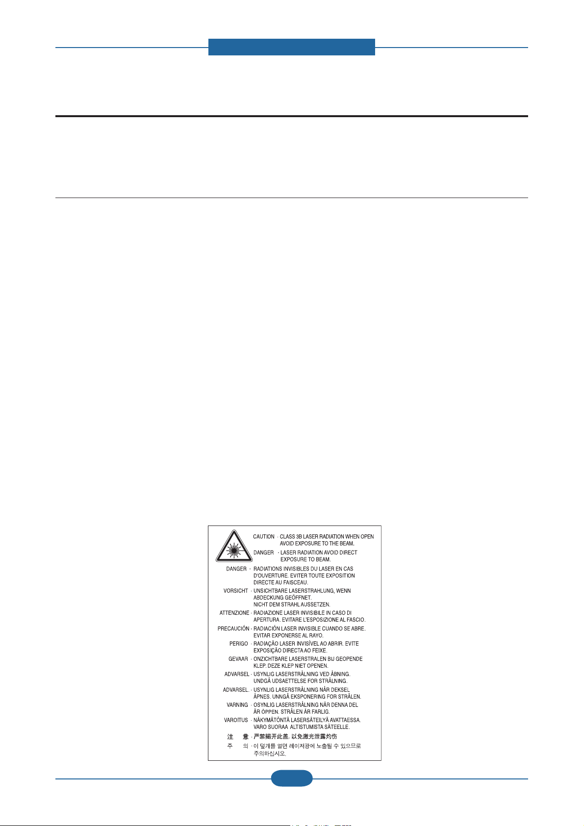
(3) Laser Safety Statement
The printer is certi ed in the U.S. to conform to the requirements of DHHS 21 CFR, chapter 1 Subchapter
J for Class I(1) laser products, and elsewhere is certi ed as a Class I laser product conforming to the
requirements of IEC 60825-1:1993 + A1:1997 + A2:2001. Class I laser products are not considered to
be hazardous. The laser system and printer are designed so there is never any human access to laser
radiation above a Class I level during normal operation, user maintenance or prescribed service condition.
• Wavelength: 800 nm
• Beam divergence
- Paraller: 12 degrees
- Perpendicular: 35 degrees
• Maximum power or energy output: 15 mW
WARNING
Never operate or service the printer with the protective cover removed from Laser/Scanner assembly. The
reflected beam, although invisible, can damage your eyes. When using this product, these basic safety
precautions should always be followed to reduce risk of fire, electric shock, and injury to persons:
Service Manual
SCX-483x/5x3x series
1-1
Samsung Electronics
Page 6

1. Precautions
1.2 Caution for safety
1.2.1 Toxic material
This product contains toxic materials that could cause illness if ingested.
(1) If the LCD control panel is damaged it is possible for the liquid inside to leak. This liquid is toxic. Contact
with the skin should be avoided, wash any splashes from eyes or skin immediately and contact your
doctor. If the liquid gets into the mouth or is swallowed see a doctor immediately.
(2) Please keep Drum cartridge and Toner Cartridge away from children. The toner powder contained in the
Drum cartridge and Toner Cartridge may be harmful and if swallowed you should contact a doctor.
1.2.2 Electric Shock and Fire Safety Precautions
Failure to follow the following instructions could cause electric shock or potentially cause a re.
(1) Use only the correct voltage, failure to do so could damage the printer and potentially cause a re or
electric shock.
(2) Use only the power cable supplied with the printer. Use of an incorrectly speci ed cable could cause the
cable to overheat and potentially cause a re.
(3) Do not overload the power socket, this could lead to overheating of the cables inside the wall and could
lead to a re.
(4) Do not allow water or other liquids to spill into the printer, this can cause electric shock. Do not allow
paper clips, pins or other foreign objects to fall into the printer these could cause a short circuit leading to
an electric shock or re hazard.
(5) Never touch the plugs on either end of the power cable with wet hands, this can cause electric shock.
When servicing the printer remove the power plug from the wall socket.
(6) Use caution when inserting or removing the power connector. The power connector must be inserted
completely otherwise a poor contact could cause overheating possibly leading to a re. When removing
the power connector grip it rmly and pull.
(7) Take care of the power cable. Do not allow it to become twisted, bent sharply round corners or other
wise damaged. Do not place objects on top of the power cable. If the power cable is damaged it could
overheat and cause a re or exposed cables could cause an electric shock. Replace a damaged power
cable immediately, do not reuse or repair the damaged cable. Some chemicals can attack the coating on
the power cable, weakening the cover or exposing cables causing re and shock risks.
(8) Ensure that the power sockets and plugs are not cracked or broken in any way. Any such defects should
be repaired immediately. Take care not to cut or damage the power cable or plugs when moving the
machine.
(9) Use caution during thunder or lightening storms. Samsung recommend that this machine be disconnected
from the power source when such weather conditions are expected. Do not touch the machine or the
power cord if it is still connected to the wall socket in these weather conditions.
(10) Avoid damp or dusty areas, install the printer in a clean well ventilated location. Do not position the
machine near a humidi er. Damp and dust build up inside the machine can lead to overheating and
cause a re.
(11) Do not position the printer in direct sunlight. This will cause the temperature inside the printer to rise
possibly leading to the printer failing to work properly and in extreme conditions could lead to a re.
(12) Do not insert any metal objects into the machine through the ventilator fan or other part of the casing, it
could make contact with a high voltage conductor inside the machine and cause an electric shock.
Service Manual
SCX-483x/5x3x series
1-2
Samsung Electronics
Page 7

1. Precautions
1.2.3 Handling Precautions
The following instructions are for your own personal safety, to avoid injury and so as not to damage the
printer
(1) Ensure the printer is installed on a level surface, capable of supporting its weight. Failure to do so could
cause the printer to tip or fall.
(2) The printer contains many rollers, gears and fans. Take great care to ensure that you do not catch your
ngers, hair or clothing in any of these rotating devices.
(3) Do not place any small metal objects, containers of water, chemicals or other liquids close to the printer
which if spilled could get into the machine and cause damage or a shock or re hazard.
(4) Do not install the machine in areas with high dust or moisture levels, beside on open window or close to a
humidi er or heater. Damage could be caused to the printer in such areas.
(5) Do not place candles, burning cigarettes, etc on the printer, These could cause a re.
1.2.4 Assembly / Disassembly Precautions
Replace parts carefully, always use Samsung parts. Take care to note the exact location of parts and also
cable routing before dismantling any part of the machine. Ensure all parts and cables are replaced correctly.
Please carry out the following procedures before dismantling the printer or replacing any parts.
(1) Check the contents of the machine memory and make a note of any user settings. These will be erased if
the mainboard or network card is replaced.
(2) Ensure that power is disconnected before servicing or replacing any electrical parts.
(3) Disconnect printer interface cables and power cables.
(4) Only use approved spare parts. Ensure that part number, product name, any voltage, current or
temperature rating are correct.
(5) When removing or re- tting any parts do not use excessive force, especially when tting screws into
plastic.
(6) Take care not to drop any small parts into the machine.
(7) Handling of the OPC Drum
- The OPC Drum can be irreparably damaged if it exposed to light.
Take care not to expose the OPC Drum either to direct sunlight or to uorescent or incandescent
room lighting. Exposure for as little as 5 mins can damage the surface? photoconductive properties
and will result in print quality degradation. Take extra care when servicing the printer. Remove the
OPC Drum and store it in a black bag or other lightproof container. Take care when working with the
covers(especially the top cover) open as light is admitted to the OPC area and can damage the OPC
Drum.
- Take care not to scratch the green surface of OPC Drum Unit.
If the green surface of the Drum Cartridge is scratched or touched the print quality will be compromised.
Service Manual
SCX-483x/5x3x series
1-3
Samsung Electronics
Page 8

1. Precautions
1.2.5 Disregarding this warning may cause bodily injury
(1) Be careful with the high temperature part.
The fuser unit works at a high temperature. Use caution when working on the printer. Wait for the fuser to
cool down before disassembly.
(2) Do not put nger or hair into the rotating parts.
When operating a printer, do not put hand or hair into the rotating parts (Paper feeding entrance, motor,
fan, etc.). If do, you can get harm.
(3) When you move the printer.
This printer weighs approx. 16 kg (35.27 lbs) including toner cartridge and cassette. Use safe lifting and
handling techniques. Use the lifting handles located on each side of the machine. Back injury could be
caused if you do not lift carefully.
(4) Ensure the printer is installed safely.
The printer weighs approx. 16 kg (35.27 lbs), ensure the printer is installed on a level surface, capable of
supporting its weight. Failure to do so could cause the printer to tip or fall possibly causing personal injury
or damaging the printer.
(5) Do not install the printer on a sloping or unstable surface. After installation, double check that the printer
is stable.
Service Manual
SCX-483x/5x3x series
1-4
Samsung Electronics
Page 9

1. Precautions
1.3 ESD Precautions
Certain semiconductor devices can be easily damaged by static electricity. Such components are commonly
called “Electrostatically Sensitive (ES) Devices” or ESDs. Examples of typical ESDs are: integrated circuits,
some eld effect transistors, and semiconductor “chip” components.
The techniques outlined below should be followed to help reduce the incidence of component damage
caused by static electricity.
Caution >>Be sure no power is applied to the chassis or circuit, and observe all other safety precautions.
1. Immediately before handling a semiconductor component or semiconductor-equipped assembly, drain
off any electrostatic charge on your body by touching a known earth ground. Alternatively, employ a
commercially available wrist strap device, which should be removed for your personal safety reasons prior
to applying power to the unit under test.
2. After removing an electrical assembly equipped with ESDs, place the assembly on a conductive surface,
such as aluminum or copper foil, or conductive foam, to prevent electrostatic charge buildup in the vicinity
of the assembly.
3. Use only a grounded tip soldering iron to solder or desolder ESDs.
4. Use only an “anti-static” solder removal device. Some solder removal devices not classi ed as “anti-static”
can generate electrical charges suf cient to damage ESDs.
5. Do not use Freon-propelled chemicals. When sprayed, these can generate electrical charges suf cient to
damage ESDs.
6. Do not remove a replacement ESD from its protective packaging until immediately before installing it. Most
replacement ESDs are packaged with all leads shorted together by conductive foam, aluminum foil, or a
comparable conductive material.
7. Immediately before removing the protective shorting material from the leads of a replacement ESD, touch
the protective material to the chassis or circuit assembly into which the device will be installed.
8. Maintain continuous electrical contact between the ESD and the assembly into which it will be installed,
until completely plugged or soldered into the circuit.
9. Minimize bodily motions when handling unpackaged replacement ESDs. Normal motions, such as
the brushing together of clothing fabric and lifting one’s foot from a carpeted oor, can generate static
electricity suf cient to damage an ESD.
Service Manual
SCX-483x/5x3x series
1-5
Samsung Electronics
Page 10

2. Product specifications and descriptions
2. Product specifications and descriptions
2.1 Specifications
2.1.1 Product Overview
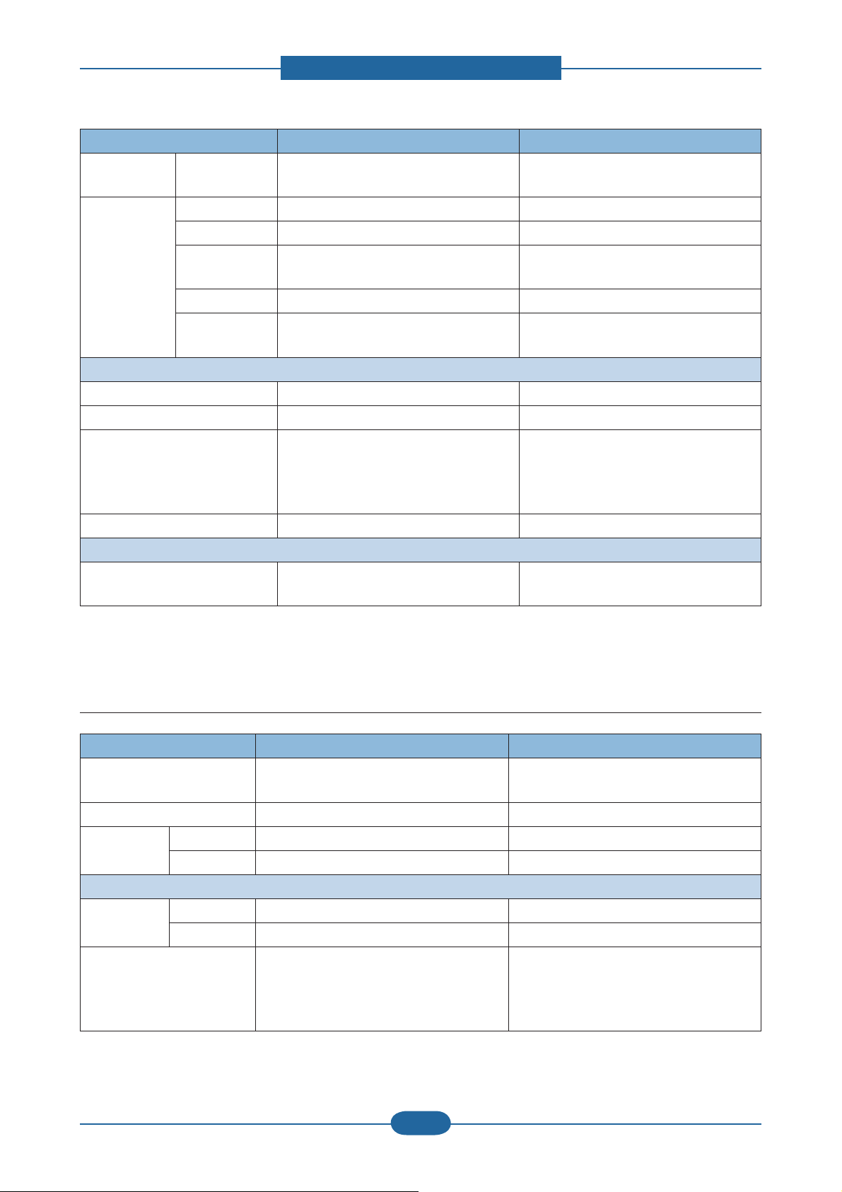
1. Speed
• SCX-483x series : 31 ppm in A4 / 33 ppm in Letter
• SCX-5x3x series : 35 ppm in A4 / 37 ppm in Letter
2. Processor
• SCX-483xFD/HD : 360 MHz
• SCX-483xFR / SCX-5x3x series : 600 MHz
3. Printer Languages
• PCL6, PS3
4. Memory (Std / Max)
• SCX-483xFD/HD : 128 MB / 384 MB
• SCX-483xFR / SCX-5x3x series : 256MB / 768 MB
5. Interfaces
• High Speed USB 2.0
• 10/100 BaseTX network connector (SCX-483xFD/HD)
• 10/100/1000 BaseTX network connector
(SCX-483xFR / SCX-5x3x series)
• 802.11b/g/n wireless LAN (SCX-573xFW)
6. ADF (SCX-483xFD/HD) /
RADF (SCX-483xFR/ SCX-5x3x series)
7. Toner cartridge (Initial / Sales)
• SCX-483x series : 2K / 2K, 5K
• SCX-5x3x series : 5K / 2K, 5K, 10K
Service Manual
SCX-483x/5x3x series
2-1
Samsung Electronics
Page 11

2. Product specifications and descriptions
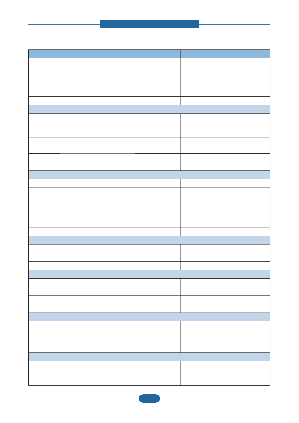
2.1.2 Features by models
SCX-4833FD
Features
Print, Copy, Scan, Fax ● ● ● ●
Hi-Speed USB 2.0 ● ● ● ●
IEEE 1284 Parallel ○ ○ ○ ○
Network Interface
Ethernet 10/100 Base
TX wired LAN
Network Interface
Ethernet 10/100/1000
Base TX wired LAN
Network Interface
802.11b/g/n wireless
LAN
Eco printing ● ● ● ●
Duplex (2-sided) printing ● ● ● ●
Samsung Easy Printer
Manager
SCX-4835FD
SCX-4833HD
●
● ● ● ●
SCX-4833FR
SCX-4835FR
● ● ●
SCX-5637FR
SCX-5639FR
SCX-5637HR
SCX-5737FW
SCX-5739FW
●
Memory ○ ○ ○ ○
Tray 2 (520 sheets) ○ ○ ○ ○
SyncThru Web Service " ● ● ● ●
Automatic Document
Feeder (ADF)
Reversed Automatic
Document Feeder
(RADF)
( ●: Included, ○: Optional, Blank: Not available)
●
● ● ●
Service Manual
SCX-483x/5x3x series
2-2
Samsung Electronics
Page 12
2. Product specifications and descriptions
2.1.3 Specifications
• Product Specifications are subject to change without notice. See below for product specifications.
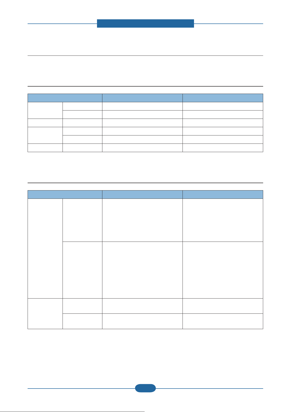
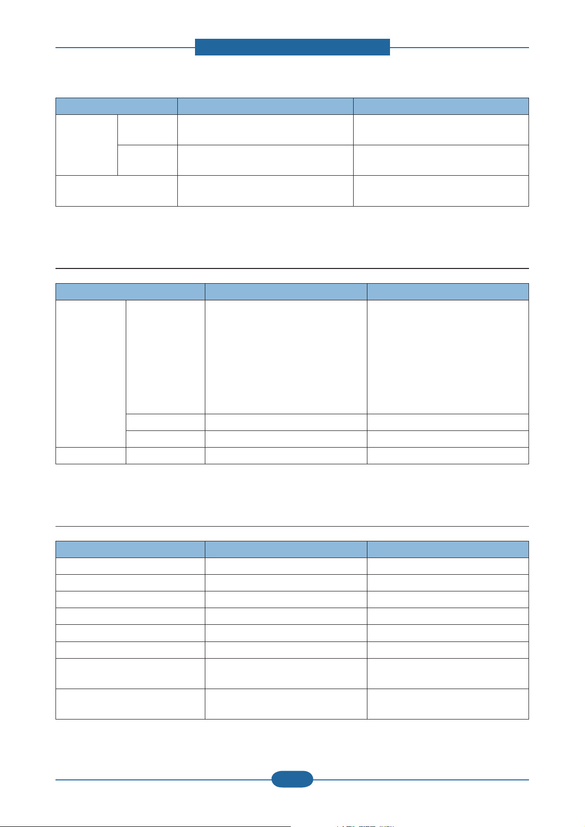
2.1.3.1 General Print Engine
Item SCX-483x series SCX-5x3x series
Engine Speed Simplex Up to 31 ppm in A4 (33 ppm in Letter) Up to 35 ppm in A4 (37 ppm in Letter)
Duplex Up to 15 ipm in A4 (16 ipm in Letter) Up to 17 ipm in A4 (18 ipm in Letter)
Warmup time From Sleep 15 sec 15 sec
FPOT From Ready As fast as 8 sec As fast as 8 sec
From Sleep As fast as 15.5 sec As fast as 15.5 sec
Resolution - Up to 1,200 x 1,200 dpi effective output Up to 1,200 x 1,200 dpi effective output
2.1.3.2 Copier specification
Item SCX-483x series SCX-5x3x series
Copy Speed SDMC
(SDMC: Single
Document Multiple
Copy)
MDMC
(MDMC: Multiple
Document Multiple
Copy)
FCOT From Ready @
platen
From Sleep @
platen
- Simplex to Simplex (1-1) : 30 sec
- Simplex to Duplex (1-2) : 15 sec
- Duplex to Simplex (2-1) : 30 sec (only
483xFR)
- Duplex to Duplex (2-2) : 15 sec (only
483xFR)
- Simplex to Simplex (1-1) : 20 sec
(483xFD/HD) / 24 sec (483xFR)
- Simplex to Duplex (1-2) : 24 sec
(483xFD/HD) / 17 sec (483xFR)
- Duplex to Simplex (2-1) : 10 sec (only
483xFR)
- Duplex to Duplex (2-2) : 10 sec (only
483xFR)
As fast as 15 sec As fast as 12 sec
As fast as 23 sec As fast as 20 sec
- Simplex to Simplex (1-1) : 30 sec
- Simplex to Duplex (1-2) : 15 sec
- Duplex to Simplex (2-1) : 30 sec
- Duplex to Duplex (2-2) : 15 sec
- Simplex to Simplex (1-1) : 24 sec
- Simplex to Duplex (1-2) : 17 sec
- Duplex to Simplex (2-1) : 10 sec
- Duplex to Duplex (2-2) : 10 sec
Service Manual
SCX-483x/5x3x series
2-3
Samsung Electronics
Page 13
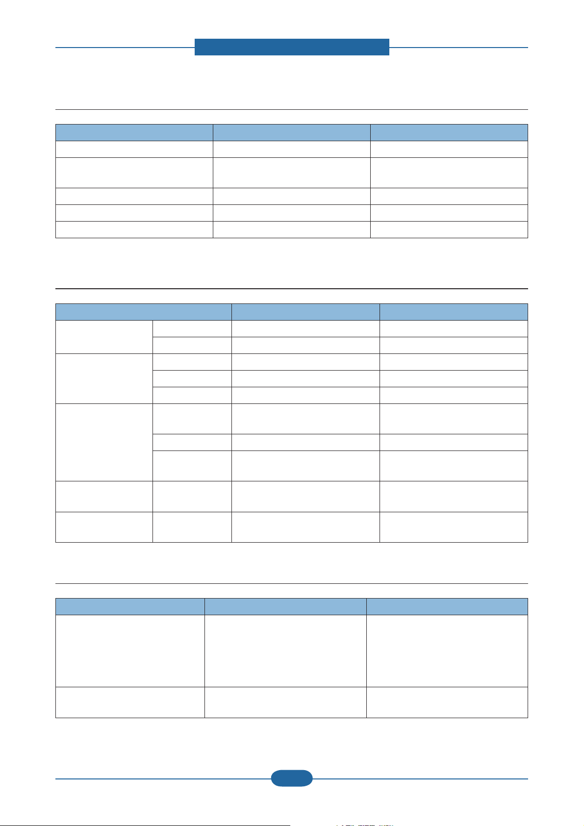
2. Product specifications and descriptions
Item SCX-483x series SCX-5x3x series
Resolution Text
Text and Photo
- Scan
300x300 dpi @ ADF
600x300 dpi @ DADF
- Scan
600x300 dpi @ DADF
600x600 dpi @ Platen
600x600 dpi @ Platen
- Print
- Print
600x600 dpi
600x600 dpi
Contrast Level 1 1 levels 1 1 levels
Darkness Level 1 1 levels 1 1 levels
Multicopy Max 99 copies Max 99 copies
2.1.3.3 Scanner Specification
Item SCX-483x series SCX-5x3x series
Scan Method CIS CIS
Scan Speed Black 20 ipm @ 300 dpi (483xFD)
24 ipm @ 300 dpi (483xFR)
Gray 20 ipm @ 300 dpi (483xFD)
24 ipm @ 300 dpi (483xFR)
Color 6 ipm @ 300 dpi (483xFD)
8 ipm @ 300 dpi (483xFR)
Resolution Optical 1,200 x 1,200 dpi 1,200 x 1,200 dpi
Scanning Size ADF/DADF Max. Document Width : 216 mm
Effective Scan Width : 208 mm
Max. Document Length : 356 mm
Effective Scan Lenght : 348 mm
Platen Max. Document Width : 216 mm
Effective Scan Width : 208 mm
Max. Document Length : 297 mm
Effective Scan Lenght : 289 mm
Scan Format PDF, TIFF, TIFF uncompress, Multi-
TIFF, Multi-TIFF-uncompress, JPEG
24 ipm @ 300 dpi
24 ipm @ 300 dpi
8 ipm @ 300 dpi
Max. Document Width : 216 mm
Effective Scan Width : 208 mm
Max. Document Length : 356 mm
Effective Scan Lenght : 348 mm
Max. Document Width : 216 mm
Effective Scan Width : 208 mm
Max. Document Length : 297 mm
Effective Scan Lenght : 289 mm
PDF, TIFF, TIFF uncompress, MultiTIFF, Multi-TIFF-uncompress, JPEG
Service Manual
SCX-483x/5x3x series
2-4
Samsung Electronics
Page 14
2. Product specifications and descriptions
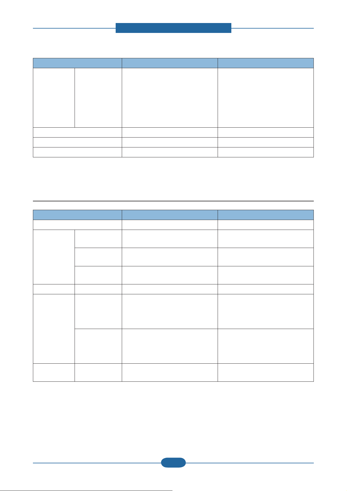
2.1.3.4 Fax Specification
Item SCX-483x series SCX-5x3x series
Compression Method MH/MR/MMR, JBIG, JPEG MH/MR/MMR, JBIG, JPEG
Modem Speed 33.6 Kbps 33.6 Kbps
Transmission Speed Approx. 3 sec Approx. 3 sec
TX Resolution Normal 98 x 203 dpi 98 x 203 dpi
Fine 196 x 203 dpi 196 x 203 dpi
Gray Scale / Halftones 256 levels 256 levels
Fax Memory Type USB Memory stick USB Memory stick
Std 6 MB 50 MB
Page Capacity 480 pages 4000 pages
2.1.3.5 Controller & S/W
Item SCX-483x series SCX-5x3x series
Processor - SCX-483xFD/HD : 360 MHz
- SCX-483xFR : 600 MHz
Memory Std. - SCX-483xFD/HD : 128 MB
- SCX-483xFR : 256 MB
Max. - SCX-483xFD/HD : 384 MB
- SCX-483xFR : 768 MB
Flash - SCX-483xFD/HD : 16 MB
- SCX-483xFR : 32 MB
Printer Languages PCL, PS3 PCL, PS3
Fonts 93 scalable, 1 bitmap 93 scalable, 1 bitmap
600 MHz
256 MB
768MB
32 MB
Service Manual
SCX-483x/5x3x series
2-5
Samsung Electronics
Page 15

2. Product specifications and descriptions
Item SCX-483x series SCX-5x3x series
Driver Default Driver PCL PCL
Install PCL6 / PS3 PCL6 / PS3
Supporting OS Windows 2000/XP (32/64 bits) /
Vista (32/64 bits) /
2003 Server (32/64 bits) /
2008 Server(32/64 bits) /
7 (32/64 bits) /2008 Server R2
V arious Linux OS:
Fedora Core 4, 5, 6
Fedora 7, 8, 9, 10, 1 1, 12
RedHat Enterprise Linux WS 4, 5
SuSE 10.0, 10.1
openSuSE 10.2, 10.3, 1 1.0, 11.1, 11.2
SuSE Linux Enterprise Desktop 10, 1 1
Debian 4.0, 5.0
Ubuntu 5.04, 5.10, 6.04, 6.10, 7.04, 7.10,
8.04, 8.10, 9.04, 9.10
Mandriva 2005LE, 2006, 2007, 2007.1,
2008, 2008.1, 2009, 2009.1
Windows 2000/XP (32/64 bits) /
Vista (32/64 bits) /
2003 Server (32/64 bits) /
2008 Server(32/64 bits) /
7 (32/64 bits) /2008 Server R2
V arious Linux OS:
Fedora Core 4, 5, 6
Fedora 7, 8, 9, 10, 1 1, 12
RedHat Enterprise Linux WS 4, 5
SuSE 10.0, 10.1
openSuSE 10.2, 10.3, 1 1.0, 11.1, 11.2
SuSE Linux Enterprise Desktop 10, 1 1
Debian 4.0, 5.0
Ubuntu 5.04, 5.10, 6.04, 6.10, 7.04, 7.10,
8.04, 8.10, 9.04, 9.10
Mandriva 2005LE, 2006, 2007, 2007.1,
2008, 2008.1, 2009, 2009.1
Mac OS 10.3 ~ 10.6 Mac OS 10.3 ~ 10.6
Citrix Presentation Server
Windows Terminal Services
WHQL Windows 2000/XP(32/64bits)/
Vista(32/64bits)/2003
Server(32/64bits)/2008 Server(32/64bits)/
7(32/64bit)/2008 Server R2(64bits)
Compatibility SPL & PCL6: Win 2000/
XP(32/64bits)/2003 Server(32/64bits)/
Vista(32/64bits)/2008
Server(32/64bits)/7(32/64bits)
PS3: Win 2000/XP(32/64bits)/
Vista(32/64bits)/2003
server(32/64bits)/2008
Server(32/64bits)/7 (32/64bits) PPD,
Mac PPD, Linux PPD
Citrix Presentation Server
Windows Terminal Services
Windows 2000/XP(32/64bits)/
Vista(32/64bits)/2003
Server(32/64bits)/2008 Server(32/64bits)/
7(32/64bit)/2008 Server R2(64bits)
SPL & PCL6: Win 2000/
XP(32/64bits)/2003 Server(32/64bits)/
Vista(32/64bits)/2008
Server(32/64bits)/7(32/64bits)
PS3: Win 2000/XP(32/64bits)/
Vista(32/64bits)/2003
server(32/64bits)/2008
Server(32/64bits)/7 (32/64bits) PPD,
Mac PPD, Linux PPD
Wired Network Protocol TCP/IP, Ethertalk, SNMP , HTTP 1.1 TCP/IP, Ethertalk, SNMP , HTTP 1.1
Supporting OS Windows 2000/XP(32/64bits)/2003
Server(32/64bits)/Vista(32/64bits)/2008
Server(32/64bits)
Mac OS 8.6~9.2, 10.1~10.5
V arious Linux OS including Red Hat 8~9,
Fedora Core 1~4, Mandrake 9.2~10.1,
and SuSE 8.2~9.2
NetWare 5.x, 6.x (TCP/IP Only)
Unix HP-UX
Windows 2000/XP(32/64bits)/2003
Server(32/64bits)/Vista(32/64bits)/2008
Server(32/64bits)
Mac OS 8.6~9.2, 10.1~10.5
V arious Linux OS including Red Hat 8~9,
Fedora Core 1~4, Mandrake 9.2~10.1,
and SuSE 8.2~9.2
NetWare 5.x, 6.x (TCP/IP Only)
Unix HP-UX
Service Manual
SCX-483x/5x3x series
2-6
Samsung Electronics
Page 16
2. Product specifications and descriptions
Item SCX-483x series SCX-5x3x series
Wireless
Protocol N/A Only SCX-573xFW : 802.1 1n
Network
Application Smart Panel SmartPanel for Macintosh/LINUX SmartPanel for Macintosh/LINUX
Printer Setting PSU for Macintosh/LINUX PSU for Macintosh/LINUX
Network
SyncThru Web Admin Service 5.0 SyncThru Web Admin Service 5.0
Management
IP Setting SetIP SetIP
Others Easy Printer Manager (Windows Only),
SmarThru Office , DPU, PC fax
Easy Printer Manager (Windows Only),
SmarThru Office , DPU, PC fax
Interface
IEEE 1284 Parallel Optional Optional
USB Hi-Speed USB 2.0 Hi-Speed USB 2.0
Wired Network - 483xFD/HD :Ethernet 10/100 Base TX
Ethernet 10/100/1000 Base TX (Internal)
(Internal)
- 483xFR : Ethernet 10/100/1000 Base
TX (Internal)
Wireless Network N/A Only SCX-573xFW : 802.11n
User Interface
LCD - 483xFD/HD : 2-Line
- 483xFR : 4-Line
- 563x series : 4- Line
- 573x series : 4.3 inch Touch Screen
2.1.3.6 Paper Handling
Item SCX-483x series SCX-5x3x series
Standard Capacity 250-sheet Cassette Tray, 50-sheet Multi
Purpose Tray @80g/㎡
Max. Capacity 820 sheets @ 80g/㎡ 820 sheets @ 80g/㎡
Printing Max. Size 216 x 356 mm (8.5" x 14") 216 x 356 mm (8.5" x 14")
Min. Size 76 x 127 mm (3.0" x 5.0") 76 x 127 mm (3.0" x 5.0")
Multi-purpose tray
Capacity Plain Paper 50 sheets @ 80g/㎡ 50 sheets @ 80g/㎡
Envelop 5 sheets 5 sheets
Media sizes A4, A5, A6, Letter, Legal, Folio, Oficio,
Executive, ISO B5, JIS B5, 3"x5",
Envelope(Monarch, No.10, DL, C5, C6),
Custom
250-sheet Cassette Tray, 50-sheet Multi
Purpose Tray @80g/㎡
A4, A5, A6, Letter, Legal, Folio, Oficio,
Executive, ISO B5, JIS B5, 3"x5",
Envelope(Monarch, No.10, DL, C5, C6),
Custom
Service Manual
SCX-483x/5x3x series
2-7
Samsung Electronics
Page 17
2. Product specifications and descriptions
Item SCX-483x series SCX-5x3x series
Media type Plain, Thin, Thick, Thicker, Cotton, Colored,
Envelope, Transparency, Pre-Printed,
Recycled, Labels, Bond, Card stock,
Archive
Plain, Thin, Thick, Thicker, Cotton, Colored,
Envelope, Transparency, Pre-Printed,
Recycled, Labels, Bond, Card stock,
Archive
Media weight 16~58lb (60 to 220g/㎡) 16~58lb (60 to 220g/㎡)
Sensing Paper Empty Paper Empty
Standard Cassette Tray
Capacity 250 sheets @ 80g/㎡ 250 sheets @ 80g/㎡
Media sizes A4, A5, A6, Letter, Legal, Folio, Oficio,
Executive, ISO B5, JIS B5, Custom
Media types Plain Paper, Thin, Thick, Recycled, Bond,
Cardstock, Archive
A4, A5, A6, Letter, Legal, Folio, Oficio,
Executive, ISO B5, JIS B5, Custom
Plain Paper, Thin, Thick, Recycled, Bond,
Cardstock, Archive
Media weight 16~43lb (60 to 163g/㎡) 16~43lb (60 to 163g/㎡)
Sensing Paper Empty Paper Empty
Optional Cassette Tray
Capacity 520 sheets @ 80g/㎡ 520 sheets @ 80g/㎡
Media sizes A4, A5, A6, Letter, Legal, Folio, Oficio,
Executive, ISO B5, JIS B5
Media types Plain Paper, Thin, Thick, Recycled, Bond,
Cardstock, Archive
A4, A5, A6, Letter, Legal, Folio, Oficio,
Executive, ISO B5, JIS B5
Plain Paper, Thin, Thick, Recycled, Bond,
Cardstock, Archive
Media weight 16~43lb (60 to 163g/㎡) 16~43lb (60 to 163g/㎡)
Sensing Paper Empty Paper Empty
Output Stacking
Capacity Face-Down 150 sheets @ 80g/㎡ 150 sheets @ 80g/㎡
Face-Up 1 sheet 1 sheet
Output Full sensing Yes Yes
Duplex
Supporting Built-in Built-in
Media sizes A4, Letter, Oficio, Folio, Legal A4, Letter, Oficio, Folio, Legal
Media types Plain Paper, Thin, Thick, Recycled, Bond Plain Paper, Thin, Thick, Recycled, Bond
Media weight 16~32lb (60 to 120g/㎡) 16~32lb (60 to 120g/㎡)
Document Thickness
Non-Printable
Area
Envelop 10mm(0.4") from edge(Top, Bottom, Left,
Right)
Other Media 4mm(0.16") from edge(Top, Bottom, Left,
Right)
10mm(0.4") from edge(Top, Bottom, Left,
Right)
4mm(0.16") from edge(Top, Bottom, Left,
Right)
RADF/ADF
Type - 483xFD/HD : ADF
RADF
- 483xFR : RADF
Capacity 50 sheets @ 20lb 50 sheets @ 20lb
Service Manual
SCX-483x/5x3x series
2-8
Samsung Electronics
Page 18
2. Product specifications and descriptions
Item SCX-483x series SCX-5x3x series
Document
Size
Paper Weight - ADF : 16~28lb
Width - ADF : 142~216mm
- RADF : 145~216mm
Length - ADF : 148~356mm
- RADF : 145~356mm
- RADF : 12.5~28lb
2.1.3.7 Consumables
Item SCX-483x series SCX-5x3x series
Toner Black - Standard: Average Cartridge Yield 2K
standard pages.
- High Yield: Average cartridge Yield 5K
standard pages.
Declared cartridge yield in accordance
with ISO/IEC 19752.
145~216mm
145~356mm
12.5~ 28 lb
- Standard: Average Cartridge Yield 2K
standard pages.
- High Yield: Average cartridge Yield 5K
standard pages.
- Extra High Yield: Average cartridge
Yield 10K standard pages.
Declared cartridge yield in accordance
with ISO/IEC 19752.
Key Electronic key(CRUM) Only Electronic key(CRUM) Only
Life detect Toner gauge sensor by dot count T oner gauge sensor by dot count
Drum Yield N/A N/A
2.1.3.8 Reliability & Service
Item SCX-483x series SCX-5x3x series
Recommanded AMPV 1000 sheets/month 1500 sheets/month
Max AMPV 2500 sheets/month 3500 sheets/month
Max. Monthly Duty 50,000 sheets/month 80,000 sheets/month
MPBF 35,000 sheets 45,000 sheets
MTBF 35 months 35 months
MTTR 30 min. 30 min.
ADF / RADF Unit life - ADF : 20,000 sheets
- DADF : 80,000 sheets
SET Life Cycle 170,000 sheets or 5 years (whichever
comes first)
- DADF : 80,000 sheets
220,000 sheets or 5 years (whichever
comes first)
Service Manual
SCX-483x/5x3x series
2-9
Samsung Electronics
Page 19
2. Product specifications and descriptions
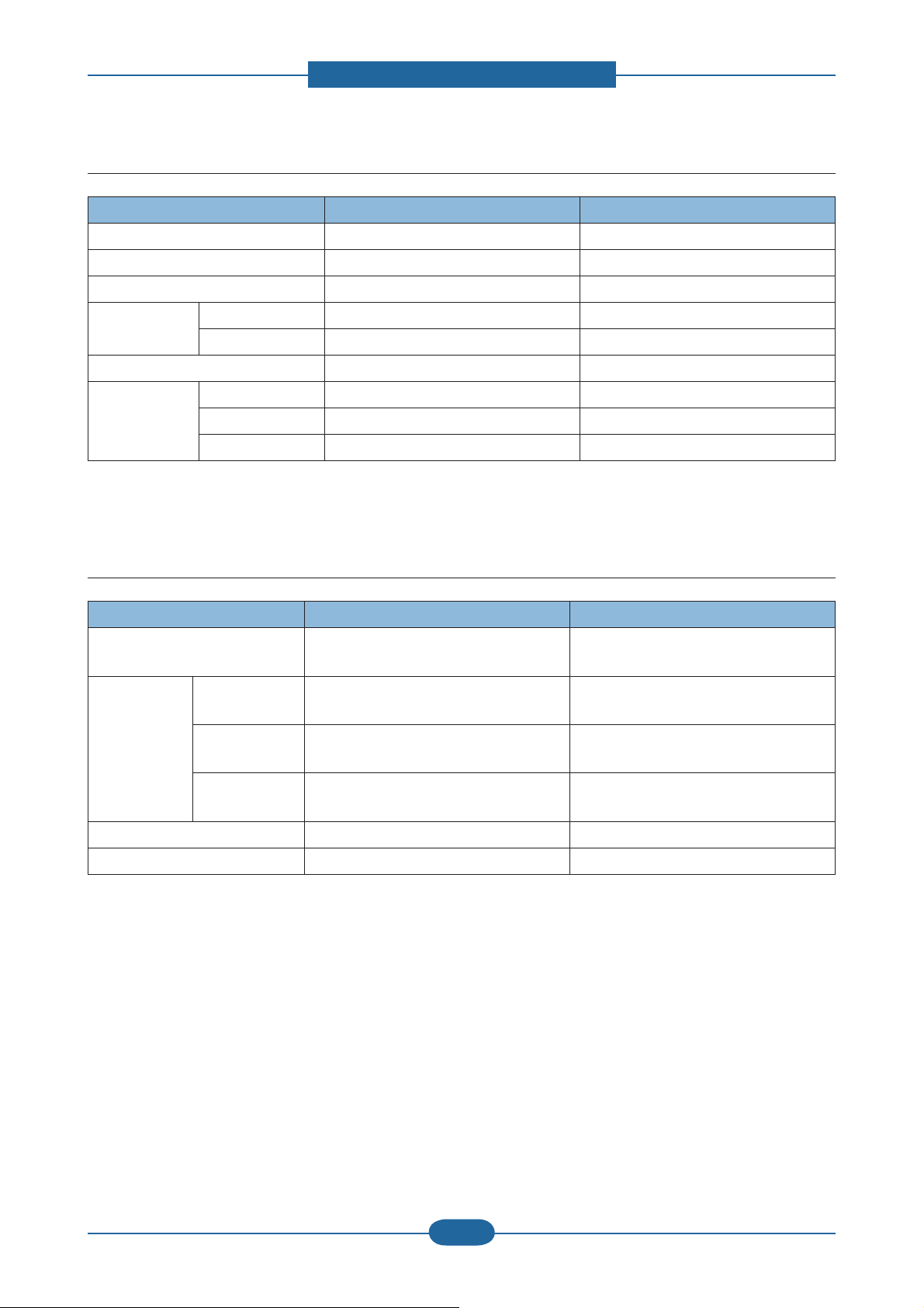
2.1.3.9 Maintenance part
Item Part Code Life
Transfer roller JC66-02842A Approx. 100,000 Pages
Fuser Unit JC91-01023A (110V)
JC91-01024A (220V)
Pick-up Roller JC73-00340A Approx. 90,000 Pages
Retard Roller JC90-01032A Approx. 60,000 Pages
RADF rubber pad JC97-03069A Approx. 20,000 pages
Approx. 90,000 Pages
2.1.3.10 Environment
Item SCX-483x series SCX-5x3x series
Operating Environment Temperature 10C to 32C 10C to 32C
Humidity 20% to 80% 20% to 80%
Acoustic Noise
Level(Sound Power/
Pressure)
Power Consumption Ready Less than 50W - 563xFR/HR : Less than 50W
Printing 51dBA 52dBA
Standby 26 dBA 26 dBA
Sleep Back Ground Level Back Ground Level
- 573xFW : Less than 65W
A VG. Less than 600W Less than 650W
Power Save Less than 8W - 563xFR/HR : Less than 8W
Dimension (W x D x H) SET - 483xFD : 407 x 424 x 382 mm
- 483xFR : 447 x 469 x 438 mm
Weight SET - 483xFD : 14 Kg
- 483xFR : 16 Kg
2.1.3.11 Options
Item SCX-483x series SCX-5x3x series
Memory * 483xFD/HD
- CLP-MEM202 : 256MB
* 483xFR
- ML-MEM170: 512 MB
Second Cassette 520-sheet Cassette Tray
(ML-S3710A)
- 573xFW : Less than 10W
447 x 469 x 438 mm
16 Kg
- ML-MEM170: 512 MB
520-sheet Cassette Tray
(ML-S3710A)
Service Manual
SCX-483x/5x3x series
2-10
Samsung Electronics
Page 20
2. Product specifications and descriptions
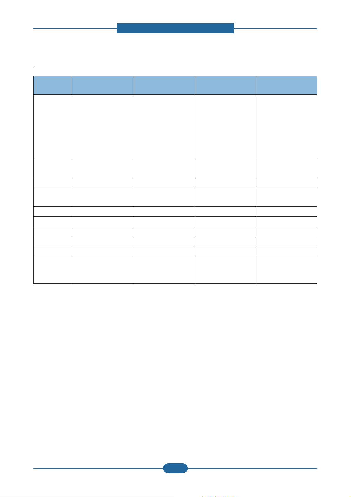
2.1.4 Model Comparison Table
Samsung
SCX-563xFR
Image
Speed
Processor 600 MHz 360 MHz - 266 MHz
Memory
(Std/Max)
Emulation PCL6/PS3 PCL6/PS3 PCL6 PCL6/PS3
MP/Cassette 50 / 250 50 / 250 50 / 250 1 / 250
SCF 520 sheets 520 sheets 250 sheets 250 / 550 sheets
Duplex Std. Std. Std. Std.
Toner Yield 2K/ 5K / 10K 2K / 5K 3K/ 8K 3.5K / 9K
Interface
35 ppm (A4)
37 ppm (Letter)
256 / 768 MB 128 / 384 MB 64 / 576 MB 64 / 64 MB
- High speed USB 2.0
- Ethernet 10/100/1000
Base TX)
Samsung
SCX-483xFD
31 ppm (A4)
33 ppm (Letter)
- High speed USB 2.0
- Ethernet 10/100 Base
TX
Brother
MFC-8890DW
30 ppm (A4) 28 ppm (A4)
- High speed USB 2.0
- Ethernet 10/100 Base
TX
- High speed USB 2.0
- Ethernet 10/100 Base
TX
Lexmark
X264DN
Service Manual
SCX-483x/5x3x series
2-11
Samsung Electronics
Page 21
2. Product specifications and descriptions
2.2 Product Description
This chapter describes the functions and operating principal of the main component.
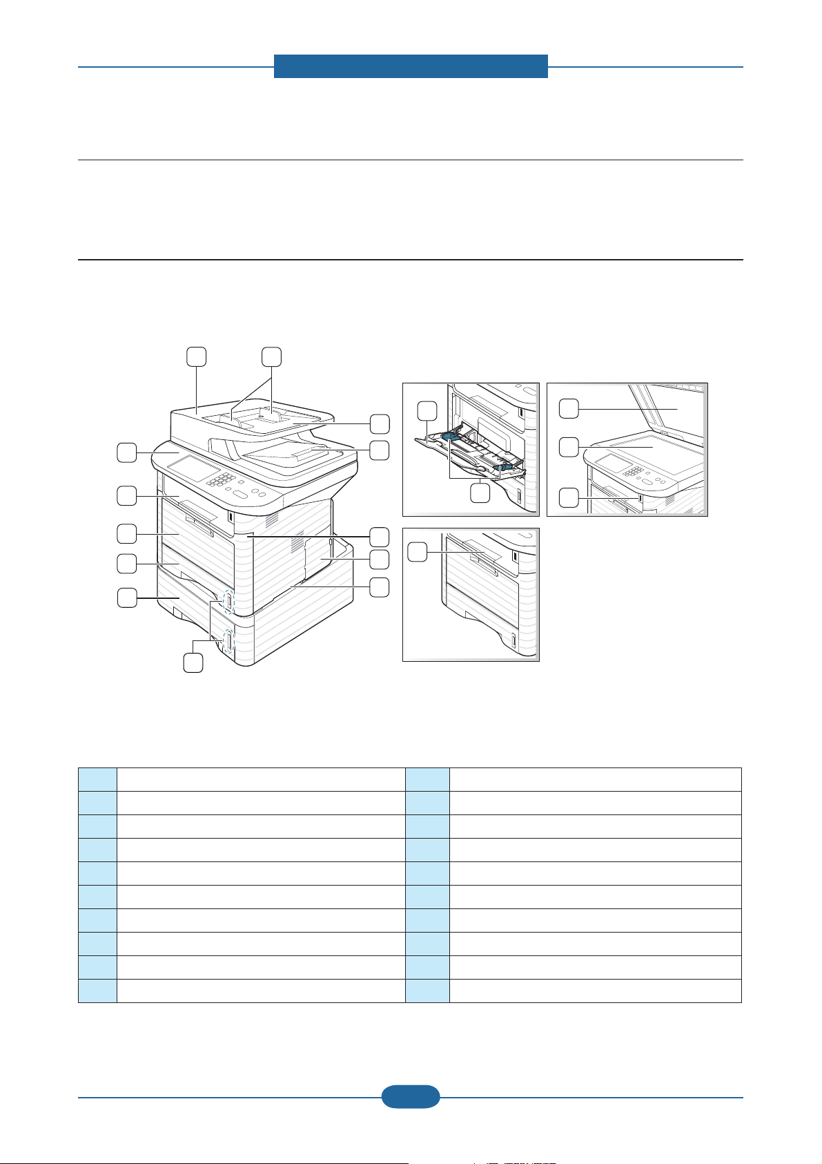
2.2.1 Front View
X
XZ
XY
XX
XW
`
_
Y
Z
[
\
]
^
X[
X\
X]
X^
X_
X`
NOTE
• This illustration may differ from your machine depending on its model.
• Some features and optional goods may not be available depending on model or country.
1 Document feeder cover 11 Multi-purpose tray
2 Document feeder width guide 12 Output tray
3 Document feeder input tray 13 Control panel
4 Document feeder output tray 14 Multi-purpose tray paper extension
5 Front cover 15 Paper width guides on a multi-purpose tray
6 Control board cover 16 Output support
7 Handle 17 Scanner lid
8 Paper level indicator 18 Scanner glass
9 Tray2 (optional) 19 USB port
10 Tray1 20 Handset
Service Manual
2-12
Samsung Electronics
SCX-483x/5x3x series
Page 22
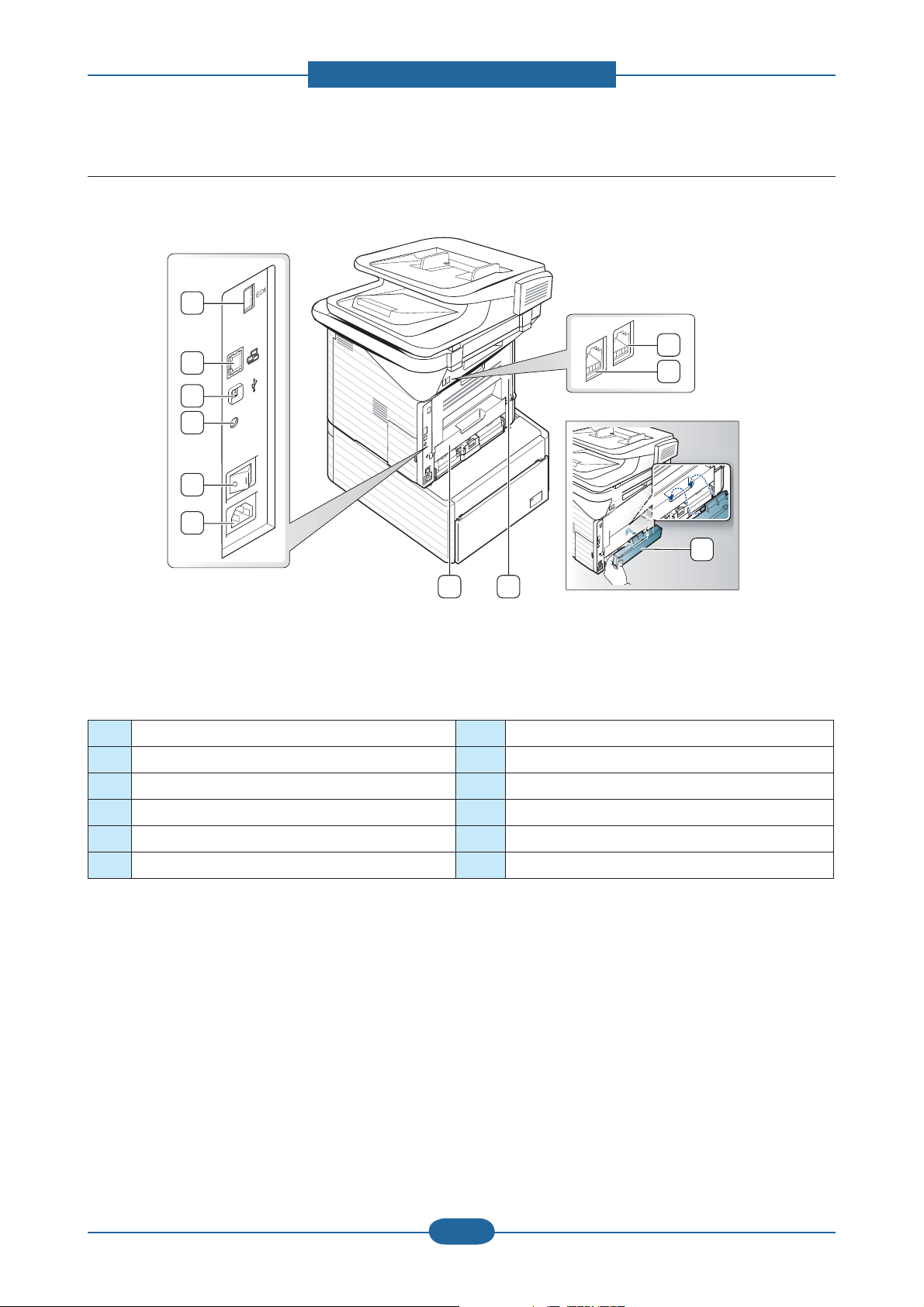
2.2.2 Rear View
X
Y
Z
[
\
]
2. Product specifications and descriptions
XX
XW
`
^ _
NOTE
• This illustration may differ from your machine depending on its model.
• Some features and optional goods may not be available depending on model or country.
1 EDI port 7 Duplex Unit
2 Network port 8 Rear cover
3 USB port 9 Tray back cover
4 IEEE 1284 parallel connector (optional) 10 Telephone line socket
5 Power-switch 11 Extension telephone socket (EXT)
6 Power receptacle
Service Manual
SCX-483x/5x3x series
2-13
Samsung Electronics
Page 23
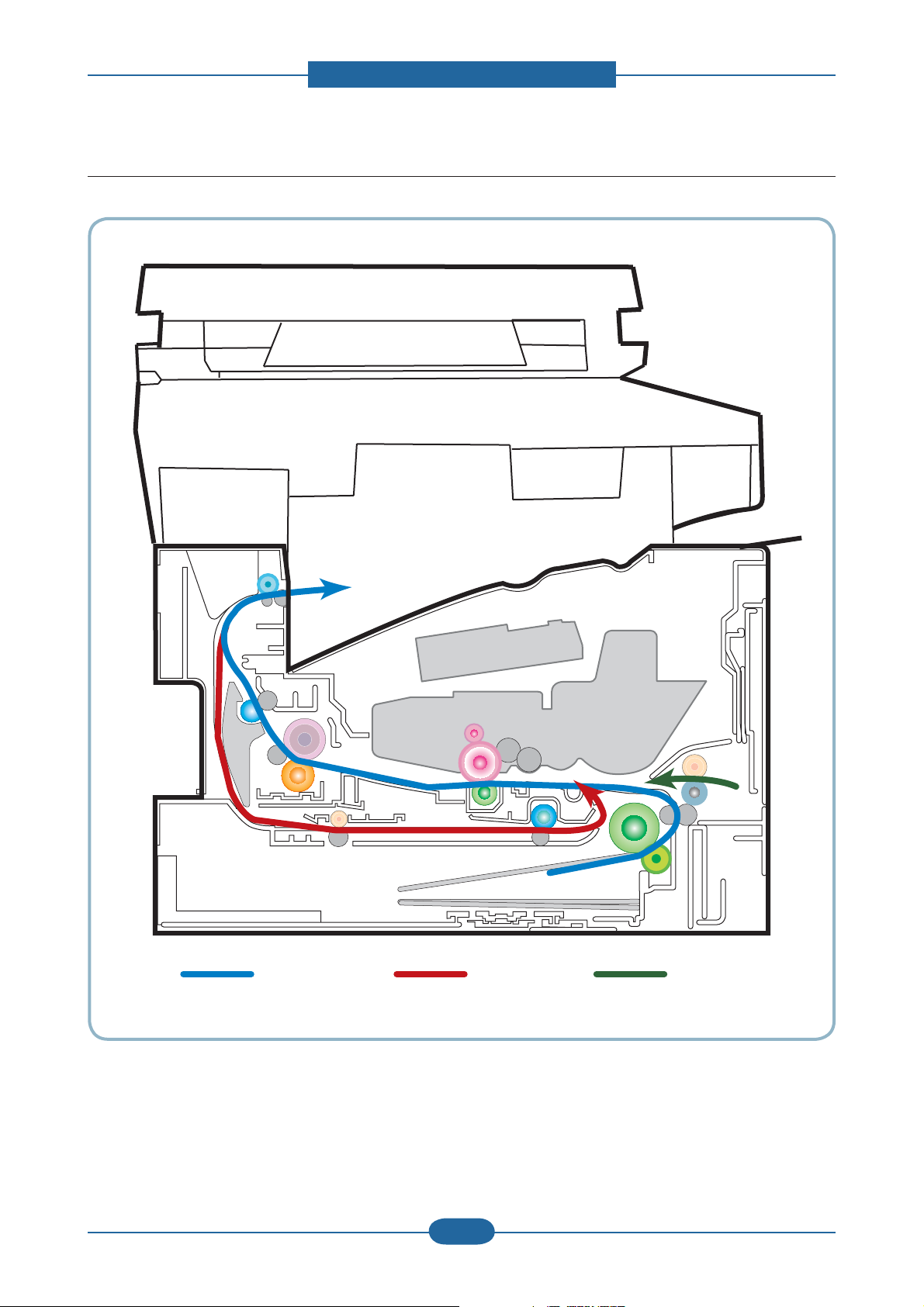
2.2.3 Paper Path
[1] Simplex [2] Duplex [3] MP
2. Product specifications and descriptions
Service Manual
SCX-483x/5x3x series
2-14
Samsung Electronics
Page 24
2. Product specifications and descriptions
1
2
3
4
7
6
8
5
11
10
9
12
14
132
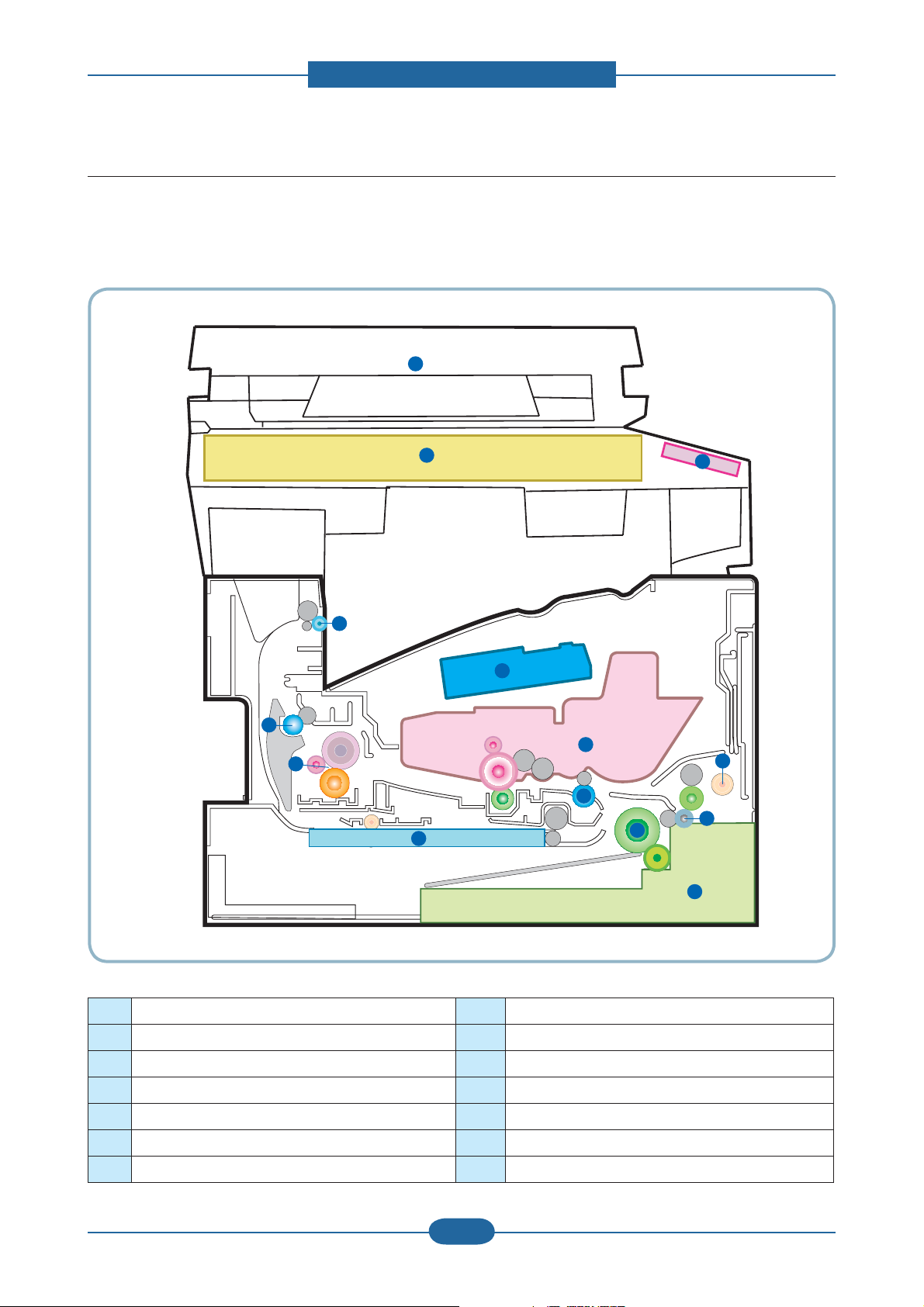
2.2.4 System layout
This model is consisted of the Engine parts and F/W. The engine parts is consisted of the mechanical
parts comprising Frame, Feeding, Developing, Driving, Transferring, Fusing, Cassette and H/W comprising
the main control board, power board, operation panel, PC Interface.
1 LSU 8 Duplex
2 Cartridge 9 Fuser
3 Regi roller 10 Exit roller1
4 MP 11 Exit roller2
5 Feed roller 12 Scanner (Platen)
6 Pick up roller 13 DADF/ADF
7 Cassette 14 OPE
Service Manual
SCX-483x/5x3x series
2-15
Samsung Electronics
Page 25
2. Product specifications and descriptions
2.2.4.1 Feeding Part
It is consists of a basic cassette, an MP tray for supplying different types of media (envelope, label, special
paper) and parts related to paper transferring.
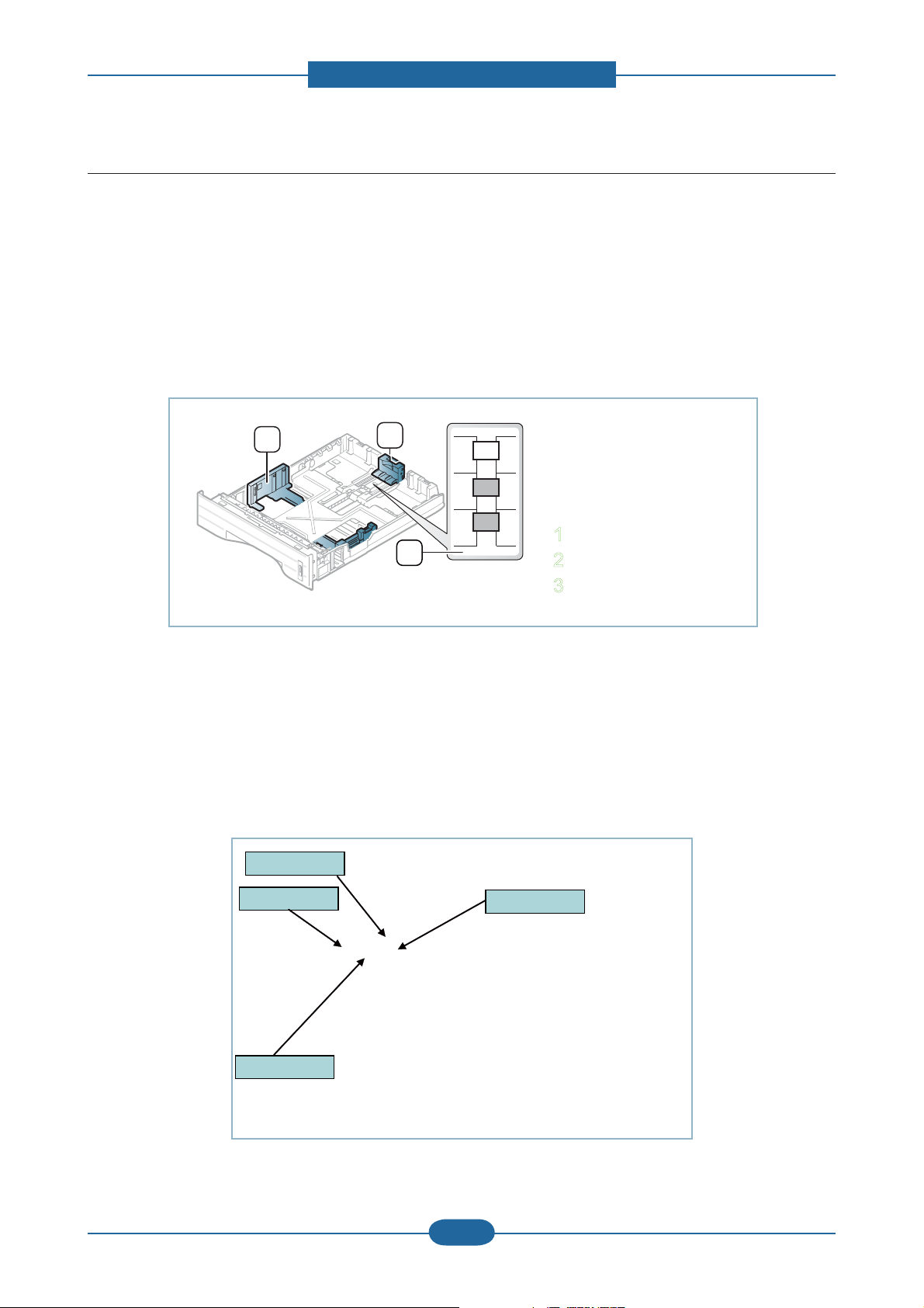
1) Tray
The basic tray is located on front side of the machine and allows feeding of common paper. Paper size is set
using the Size Guides in each tray. Adjust the Paper length/width guides to match the paper size.
3
1
LGL
A4
LTR
2
1 Paper length guide
2 Support guide
3 Paper width guide
2) Pick up / Retard Roller
When pickup takes place, the pickup roller rotates to separate and transport the paper.
The pickup roller rotates when the pickup clutch is activated. The retard roller serve to make sure
that a single sheet of paper is moved to the paper path, and the paper is moved as far as the registration
roller by the work of the feed roller. The following is a diagram of the pickup section:
Pickup Roller
Pickup Roller
Service Manual
SCX-483x/5x3x series
Feed Roller
Feed Roller
Retard Roller
Retard Roller
2-16
Regi. Roller
Regi. Roller
Samsung Electronics
Page 26

2. Product specifications and descriptions
3) Registration roller
It has a paper arranging function, paper transferring function, paper detecting function, jam removing
function, and so on.
4) MP tray
The multi-purpose tray can hold special sizes and types of print material, such as postcards, note cards, and
envelopes. It is useful for single page printing on letterhead or colored paper. It uses 3 rollers feeding method
to feed 50 sheets of general papers.
5) Duplex unit
It has paper transferring function, paper guide function, jam removing function.
It is designed for basic attachment, and the duplex feeding takes a side feeding method. Usable
papers are A4, letter, and legal size paper. For removing a jam occurred in a front part, it is designed to open
a cassette and a guide.It is designed to open a rear cover to remove a jam in a rear part. If a face up tray is
open, the duplex option cannot be used.
6) SCF (Second Cassette Feeder)
It is the same method with the main cassette, and the capacity is 520 sheets.
It has a separate driving mechanism. It is designed for a common use with a main cassette.
Service Manual
SCX-483x/5x3x series
2-17
Samsung Electronics
Page 27
2.2.4.2 Imaging unit
1) Printing process overview
2. Product specifications and descriptions
LSU
LSU
Toner Cartridge
Toner Cartridge
OPC Drum
OPC Drum
Transfer Roller
Transfer Roller
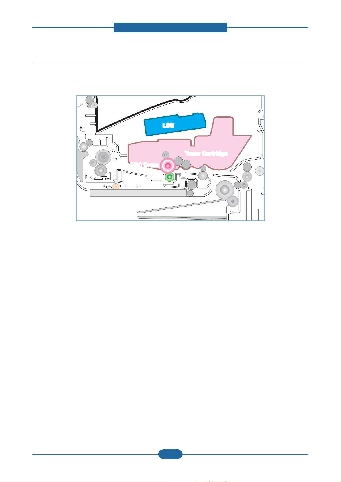
This mono printing system includes the LSU with a laser beams, a toner cartridge and transfer roller.
This machine uses single toner cartridge and dual laser beams for mono printing. The toner cartridge
consists of Drum unit and Development unit. The Drum unit has an OPC drum, cleaning blade.
The OPC drum is charged with a negative voltage by the scorotron and is exposed by the light from the LSU
(Laser Scanning unit). The light produced by a laser creates a latent image by discharging on the surface
of the OPC drum. The negatively charged toners are attracted to the latent image due to and electric filed.
The toners(real image) on the OPC drum are moved to the transfer media by the positive bias applied to the
transfer roller.
1. Charging the OPC drum: The scorotron gives the drum negative charges.
2. Laser exposure: Light produced by a laser diode irradiates the charged OPC through the lens and mirrors.
3. Development: This machine uses a dual-component development system . The magnetic roller carries negatively
charged toner to the latent image on the drum surface.
4. Transfer: The transfer rollers opposite the OPC drums transfer toner from the drums to the transfer media (e.g.
paper, OHP film, etc).
5. Cleaning for OPC drum: The cleaning blade removes remaining toners on the drum surface after image transfer
to the paper.
Service Manual
SCX-483x/5x3x series
2-18
Samsung Electronics
Page 28
2. Product specifications and descriptions
2) Toner cartridge
By using the electronic photo process, it creates a visual image. In the toner cartridge, the OPC unit and the
developing unit are in a body. The OPC unit has OPC drum and charging roller, and the toner cartridge unit
has toner, supply roller, developing roller, and blade (Doctor blade)
• Operation condition : Temp 10~30℃, Humidity 20~85% RH
• Developing Method : Non magnetic 1 element contacting method
• Toner : Non magnetic 1 element shatter type toner
• The life span of toner (ISO 19752 pattern / A4 standard)
→ Initial toner : 2K (483x series) / 5K (5x3x series)
→ Sales toner : 2K / 5K / 10K(only 5x3x series)
• Toner Residual Sensor : Dot count with CRUM(CRU Monitor)
• OPC Cleaning : Collect the toner by using cleaning blade
• Handling of wasted toner : Collect the wasted toner in the cleaning frame by using cleaning blade
• OPC Drum Protecting Shutter : None
• Classifying device for toner cartridge: ID is classified by CRUM.
ⓐ Charge Roller ⓕ Supply Roller
ⓑ Drum OPC ⓖ Charge Cleaning Roller
ⓒ Cleaning Blade ⓗ Agitator 1
ⓓ Doctor Blade ⓘ Agitator 2
ⓔ Developer Roller
Service Manual
SCX-483x/5x3x series
2-19
Samsung Electronics
Page 29
2. Product specifications and descriptions
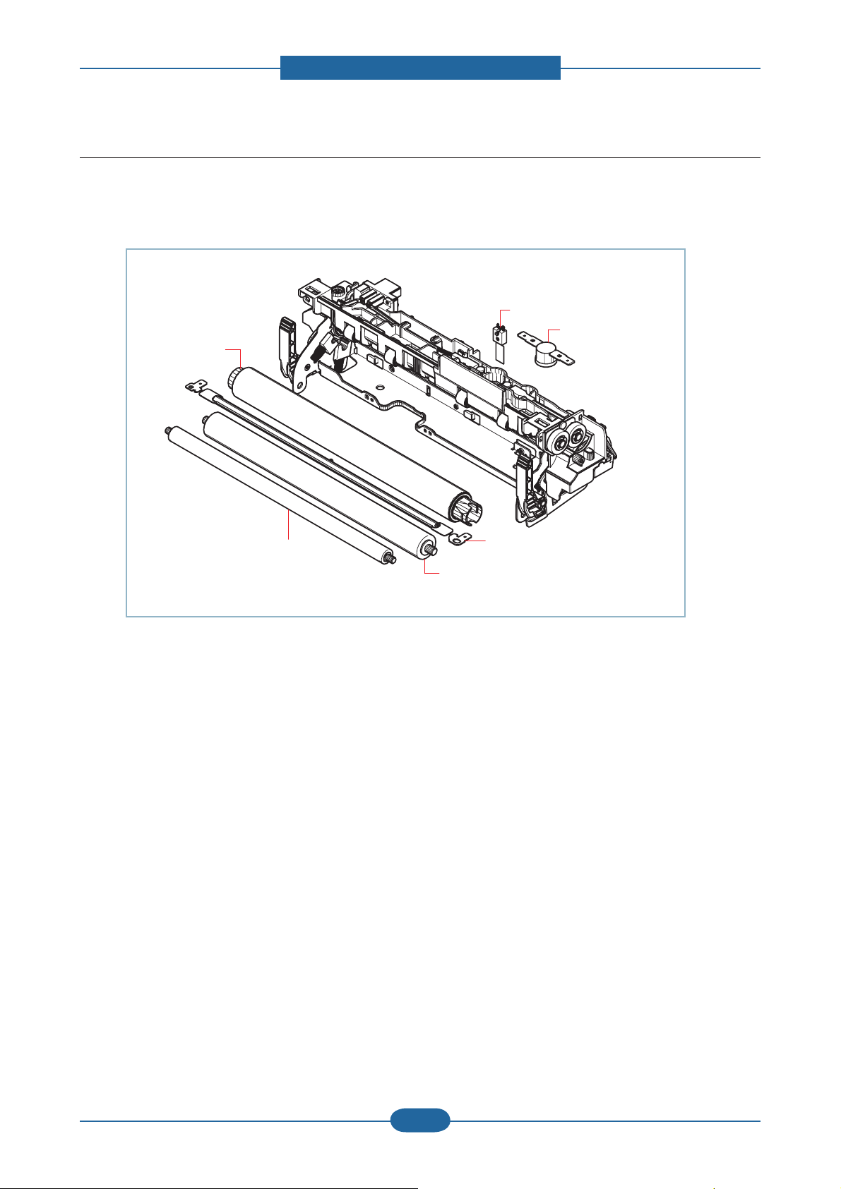
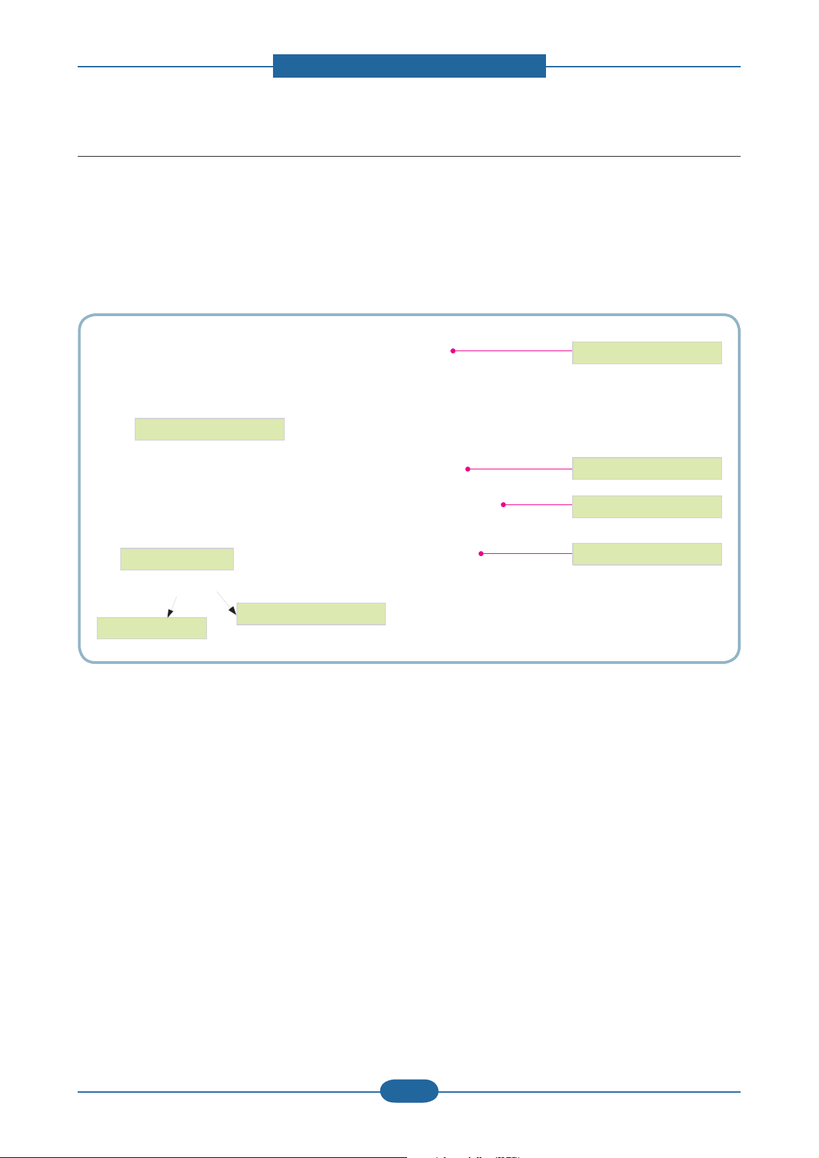
2.2.4.3 Fuser unit
It is consisted of a halogen lamp, heat roller, pressure roller, thermistor and thermostat. It sticks the toner on
a paper by heat and pressure to complete the printing job.
Thermistor
Thermostat
Heat Roller
Pressure Roller2
Pressure Roller
Halogen Lamp
1) Thermostat
When a heat lamp is overheated, a Thermostat cuts off the main power to prevent over- heating.
- Thermostat Type : Non- Contact type THERMOSTAT
- Control Temperature : 170℃ ± 5℃
2) Thermistor
It is a temperatrue detecting sensor.
- Temperature Resistance : 7㏀ (180℃ )
3) Heat roller
The heat roller transfers the heat from the lamp to apply a heat on the paper.
The surface of a heat roller is coated with Teflon, so toner does not stick to the surface.
4) Pressure roller
A pressure roller mounted under a heat roller is made of a silicon resin, and the surface also is coated with
Teflon. When a paper passes between a heat roller and a pressure roller, toner adheres to the surface of a
paper permanently.
5) Halogen Lamp
- Voltage 120 V : 115 ± 5 %
220 V : 230 ± 5 %
- Capacity : 850 Watt ± 25 W
Service Manual
SCX-483x/5x3x series
2-20
Samsung Electronics
Page 30
2. Product specifications and descriptions
OPC Drum
Photo Diode
LD Driver circit
Protector panel
LD(Laser Diode)
Polygon Mirror
Polygon Motor
Motor Driver
2.2.4.4 LSU (Laser Scanning Unit)
It is the core part of the LBP which switches from the video data received to the controller to the electrostatic
latent image on the OPC drum by controlling laser beam, exposing OPC drum, and turning principle of
polygon mirror. The OPC drum is turned with the paper feeding speed. The /HSYNC signal is created when
the laser beam from LSU reaches the end of the polygon mirror, and the signal is sent to the controller.
The controller detects the /HSYNC signal to adjust the vertical line of the image on paper. In other words,
after the /HSYNC signal is detected, the image data is sent to the LSU to adjust the left margin on paper.
The one side of the polygon mirror is one line for scanning.
Service Manual
SCX-483x/5x3x series
2-21
Samsung Electronics
Page 31

2. Product specifications and descriptions
2.2.5 Hardware configuration
The SCX-483x series Electrical Circuit System consists of the following:
• Main Controller
• OPE Controller
• DDR2 SODIMM (Option)
• SCF(Option)
• SMPS
• HVPS
Diagram of the SCX-483x series Electrical Circuit
CIS
123456789
12V
GND
CIS_SP
AFE_S IG
3.3V_C IS
PULL-UP
3CIS_CLK
SCAN_ CONTROL1
CN26(FFC 1mm)
CIS_ IF
΄ͶͺͲͽ ͷͽͲ΄
;ͳ
24VS
Pick up_CLT
24VS
Regi_CLT
zvs
y
j
101112
101112
GND
CIS_BLED
CIS_GLED
CIS_RLE D
Clock
Generator
ASM3P2863 A
12MHz
CN(2mm)
MP
24VS
MP_CLT
12345
zvs
tw
jtwz
zwlhrly
ͶͶ;
;
ͼ
3.3VS
GND
MP_SENS
1
2
MODEM
5V
GND
DATA7~
~DATA0
1
2
3~
~101112~
1
2
3~
~101112~
5V
GND
DATA7~
~DATA0
}jsr
|ziGGjsr
thpuGjsr
CN(2mm)
P_EXIT
SENSOR
3.3V
GND
PEAPER_EXIT
123
l
z
(Conexant )
R1~ADD
GND
GND
~ADDR7
HOOK_DET
nCS_MODEM
1920212223242526272829
~18
1920212223242526272829
~18
R1~ADD
GND
GND
~ADDR7
HOOK_DET
nCS_MODEM
CN9(FFC 1mm)
MODEM_IF
CN6(1.5mm)
OUTBIN
SENSOR
3.3VPS
GND
nSENS_BIN_FULL
3.3V_C_OPEN1
12345
wG
v
z
SCX-4932FN
nRD
nWR
nRING0
nM_RESET
N.C
nRD
nWR
nRST_MODE M
CHORUS3
3.3V_C_OPEN2
j
v
mGj
t G
z
o}wz
ztwz
hkmwwvzzlu
hkmjv}lyvwlu
hkmwwvzzlu
Varistor
ADF
mnuk
ZUZ}jvZUZ} ztwz
Supply
THV
S
FUSER
BIAS
INLET FUSER
pusl{
ADF_JOINT
OUT2B
1
OUT2A
t{
z{lw
24VS
GND
THV_REA D
nTHV_EN
PWM_THV
PWM_DEV_DC
PWM_MHV
PWM_FUSER_BIAS
GND
OPC MHV
T
M
kl}lsvwlyG|
C
R
U
M
GND
3.3VS
3.3V_Cover_Open
SMPS
CN4
SMPS
CN3
DEV
D
DRUM
{z
2
OUT1B
3
OUT1A
4
CN(1 .5mm)
GND
5
ADF_IF
24VS
1
GND
2
THV_READ
3
nTHV_EN
4
PWM_THV
5
PWM_DEV_DC
6
PWM_MHV
7
PWM_FUSER_BIAS
8
GND
9
GND
10
3.3VS
11
3.3V_Cover_Open
12
1
GND
2
GND
3
24VS
1
GND
CLK
2
DIO
3
3.3V_CRUM
4
24VS1
GND2
24VS1
GND2
GND
5
24V OFF
4
Relay
3
24VS
2
Fuser ON
1
1
5V_SMPS
GND
2
24V
3
GND
4
{X
CN(1. 5mm)
ADF_IF
T2BOU
T1BOU
DGN
OUT2A
OUT1A
987654321
121110
123456789
OUT2B
OUT2A
OUT1B
OUT1A
CN3(1 .5mm)
ADF_IF
CN16(2mm)
HVPS
MAIN FAN
CN12
(2mm)
CN2 3
(2mm)
CRUM
SMPS FAN
CN11
(2m m)
SMPS FAN
CN30
(1.5mm)
(2mm)
CN18
SMPS
CN17
SMPS
z
t
t{
z{lw
DGN
DGN
DGN
3.3VPS
nADF_P_POS
nADF_COVER_SE NS
nADF_P_DET
101112
GND
GND
GND
GND
3.3VPS
nADF_P_POS
nADF_COVER_SENS
CN10(2mm)
THERM
THERM_1
1
2
nADF_P_DET
MOT_DIR
PWM_MO T
123456789
10
123456789
123
4
OUT1A
OUT1B
OUT2A
OUT2B
CN4(2mm)
SCAN_MTR
CN14(2mm)
MAIN MOTOR
MOT_REA DY
MOT_EN
GND
MOT_BRE AK
GND
GND
24VS
24VS
1011121314
js
123456789
w
j
t{
iskj
t
t
GND
6
7
3.3VPS
8
GND
9
nADF_P_POS
10
nADF_CO VER_SENS
11
GND
12
nADF_P_D ET
12
Y[}z
11
10
ZUZ}z
9
8
7
6
5
4
3
2
1
ZUZ}jvX
mhu
thpu
mhu
ztwz
mhu
t
1
GND
2
24V OFF
Y[}z
Relay
3
24VS
4
Fuser ON
5
m|zlyGvu
1
5V_SMPS
GND
2
24V
3
GND
4
Y[}
\}ztwz
m|zlyG|
ONLY
N.C
3.3V
3.3V
KEYCLICK
nINT_MODEM
30
30
N.C
3.3V
3.3V
GND
nINT_MODEM
USB 2.0
3.3VS
GND
P_Empty
123456789
ltw{
z
CN(2mm)
SENSOR
SENS
z
123456789
3.3VS
GND
REGI_SEN S
ylnp
GND
nHsync
3.3V_LSU
VDO_1_P
VDO_1_N
123456789
GND
nHsync
3.3V_LSU
VDO_1_P
VDO_1_N
CN21(FFC 1mm)
3.3VS
GND
FEED_SEN S
lyhzly
mllk
z
LSU
(Dual Beam)
GND
GND
GND
nSH_1
nSH_2
VDO_2_P
VDO_2_N
10111213141516171819202122
1011121314151617181920
GND
GND
GND
nSH_1
nSH_2
VDO_2_P
VDO_2_N
LSU_IF
CN24(1.5mm)
Eraser&Duplex
DER_LEASER
S_DUPLEXnSEN
5V
GND
123
4
k
slk
N.C
nLD_ON
LD_POWER
CLK_LSU_MOT
N.C
nLD_ON
LD_POWER
CLK_LSU_MOT
΄͵Ͳ;
;ͳ
Ϳͷͽ Ͳ΄
;ͳ
ͺ΄
CN15
(1.5mm)
AIR
TEMP
TENAMBI
1
h
{
z
nREADY_LSU
nLSU_MOT_EN
nREADY_LSU
nLSU_MOT_EN
͵͵
25MH z
ͿΖΥΨΠΣΜ
GND
2
GND
24VS
GND
24VS
OPE_LC D
LCD ( 2-Line)
CN19
USB_IF
VBUSDMDP
GND
123
4
k
|zi
OPE
987654321
10
123456789
GND
SCANNER_HOME
nRST_PANE L
nPOWER_SW
GND
(1.5mm)
CN5
OPE I/F
GND
PANEL_ TXD
zG
o
z
i|ly
1
2
10
thpu
PANEL_ RXD
MOD_BUZ ZER_CON
KEYCLICK _CON
24V
24V
24V
3.3V
3.3V
3.3V
nRST_SCF
SCF_TXD
SCF_RXD
N.C
SCF_IF
nSCF_OPT
N.C
CN8(1.5mm)
N.C
GND
GND
GND
GND
GND
GND
NC
RD-
3.3V
RD+
TD-
3.3V
3.3V pullup
NETWORK_IF
LED1
3.3V
LED2
CN7
GND
GND
VBUS
DM
DP
CN28
GND
USB_IF
GND
5V
CN20
NC
POWER
PARALLEL
Rainier Hardware Team
R&D Group 2
Digital Print Division
Samsung Electronics
100409
123
5V
SCANNER_HOME
GND
1
2
3
4
5
6
7
8
9
10
11
12
13
14
15
16
17
18
1
2
3
4
5
6
7
8
9
10
11
12
13
14
1
2
3
4
1
USB TO
2
3
PARALLEL
The Main Controller controls all modules required to print, that is, LSU, HVPS, SMPS, FAN, Fuser, FAX
,Scanner etc.
The Main Controller receives print data from the host through network or USB Port or fax, Scanner. It takes
this information and generates printable video bitmap data. Engine and Video Controller are not separated.
Service Manual
2-22
Samsung Electronics
SCX-483x/5x3x series
Page 32

2. Product specifications and descriptions
The Main Controller adopts the Chorus3(360MHz) CPU, on board DDR2 memory and external memory to
perform printing and Scan jobs successfully.
The OPE Controller displays the status of the system using 16 x 2line LCD in response to user actions or the
Main controller.
The HVPS supplies high voltage for developing Process. High Voltage controlled by PWM signal from CPU.
SMPS makes +5V and +24V DC from 220V or 110 AC.
Service Manual
SCX-483x/5x3x series
2-23
Samsung Electronics
Page 33

2. Product specifications and descriptions
The SCX-483xFR/563xFR/573xFW Electrical Circuit System consists of the following:
• Main Controller
• OPE Controller
• DDR2 SODIMM(Option)
• WLAN Module(only SCX-573xFW)
• SCF(Option)
• SMPS
• HVPS
Diagram of the SCX-483xFR/563xFR/573xFW Electrical Circuit
VDO_2_P
VDO_2_N
VDO_2_P
VDO_2_N
5V
ERASER_LED
1
2
N.C
GND
nLD_ON
LD_POWER
CLK_LSU_MOT
987654321
N.C
GND
nLD_ON
LD_POWER
CLK_LSU_MOT
SDRAM
(256MB)
NOR FLASH
RTL8211D
CN(2mm)
AIR
TEMP
Ambient
Temp
Sensor
nREADY_LSU
nREADY_LSU
DDR2
(32MB)
TENAMBI
1
CLX-4833FR/5637FR
OPE_LC D
LCD ( 4-Line)
OPE(CLX-4833FR/5737FR)
GND
24VS
LCD DRV B˅D(CLX-5737FW)
nLSU_MOT_EN
123456789
GND
24VS
nLSU_MOT_EN
GND
SCANNER_HOME
nRST_PANE L
nPOWER_SW
CN
OPE I/F
25MH z
Network
USB HUB USB HUB
CN
USB_IF
USB_IF
GND
VBUSDMDP
GND
VBUSDMDP
2
123
4
1234567
Flash
Drive
CLX-5637FR
CLX-5737FW
DADF Paper Detect
Sensor
DADF Cover Open
Sensor
DADF Paper Pos
Sensor
DADF Paper Regi
Sensor
DADF Pick up
Clutch
DADF Regi
Clutch
DADF Exit
Clutch
DADF Motor
Front C over
Micro Switch
HVPS
SOL SOL SOL
MT
STEP
SMPS
Varistor
DADF
CN
1
LED_ANODE
SENSOR
2
GND
nSENS_DADF_ P_DET
3
(1.5mm)
LED_ANODE
4
GND
5
nSENS_DADF_COVER_OPEN
6
N.C
7
CN
1
LED_ANODE
SENSO R
2
GND
(1.5mm)
nSENS_DADF_ P_POS
3
LED_ANODE
4
GND
5
nSENS_DADF_ P_REGI
6
CN(2mm)
PICKUP
SOL
24V1
DADF_PICKUP_SOL
2
CN(1.5 mm)
REGI
SOL
24V1
DADF_REGI_SOL
2
CN(2mm)
24V
1
EXIT
SOL
N.C
2
DADF_EXIT_SOL
3
ADF MOT
CN(2mm)
OUT1A
1
OUT1B
2
OUT2A
3
OUT2B
4
3.3V_ Cover_Open3.3V
Supply
THV
S
FUSER
BIAS
INLET FUSER
INLET
GND
GND
G_VIN
CN(FFC 1mm)
24VS
Pickup_C LT
SPEAKER
1
2
MODEM
(Conexant )
5V
R1~ADD
nRD
GND
GND
GND
nWR
nRING0
DATA7~
~DATA0
~ADDR7
HOOK_DET
nCS_MODEM
1
2
3~
1920212223242526272829
~101112~
~18
10111213141516
1
2
10111213141516
3~
1920212223242526272829
~101112~
~18
5V
N.C
R1~ADD
GND
CIS_BLED
CIS_GLED
CIS_RLE D
EEPROM
M24C32
(M24C256)
GND
USB CLK
DATA7~
~DATA0
VCLK
MAIN CLK
GND
~ADDR7
CN(FFC 1mm)
GND
HOOK_DET
nCS_MODEM
MODEM_IF
nRD
nWR
CHORUS4
GND
R_VIN
CIS_SP
3.3V_C IS
3.3V_C IS
CIS_CLK
SCAN_C TR
LED_COMMON
CIS_IF
Clock
Generator
ASM3P2863 A
12MHz
CN(2mm)
CN(1.5mm)
CN(2mm)
P_EXIT
P_SIZE
MP
SENSOR
SENSOR
3.3V
GND
PEAPER_EXIT
3.3VPS
GND
nSENS_BIN_ FULL
3.3V_C_OPEN1
24VS
24VS
Regi_CLT
12345
SOL
SOL
MP
Regi
ClutchMPSenso r
Clutch
3.3V_C_OPEN2
MP_CLT
3.3VS
GND
MP_SENS
123
12345
3.3V_Cover_Open2
Exit
Paper
Cover
Senso r
Outbinfull
Open
Senso r
3.3V
3.3V
KEYCLICK
nM_RESET
nINT_MODEM
N.C
3.3V
3.3V
nINT_MODEM
nRST_MODE M
USB 2.0
3.3VS
GND
P_Empty
123456789
EMPTY
Senso r
N.C
30
30
GND
CN(2mm)
SENS
SENSOR
3.3VS
GND
REGI
Senso r
123456789
REGI_SEN S
GND
nHsync
3.3V_LSU
VDO_1_P
VDO_1_N
2019181716151413121110
GND
nHsync
3.3V_LSU
VDO_1_P
VDO_1_N
3.3VS
GND
FEED_SEN S
FEED
Sensor
LSU
(Dual Beam)
GND
GND
nSH_1
nSH_2
1011121314151617181920212210987654321
GND
GND
nSH_1
nSH_2
CN(FFC 1mm)
LSU_IF
CN(1.5mm)
Eraser
ERASER
LED
24VS
GND
THV_READ
nTHV_EN
PWM_THV
PWM_DEV_DC
PWM_MHV
PWM_FUSER_BIAS
GND
GND
3.3V
3.3V_Cover_Open
CN
SMPS
CN
SMPS
ThermoStat
N.C
1
12
GND
2
11
GND
3
10
CN
DADF_REGI_SOL
4
9
N.C
5
8
(1.5mm )
nSENS_DADF_P_DET
6
7
nSENS_DADF_P_REGI
7
6
DADF_MOT_SLEEP
8
5
nDADF_MOT_EN
9
4
DADF_MOT_PLS
10
3
DADF_MOT_CURRENT
11
2
DADF_MOT_DIR
12
1
1
11
GND
2
10
GND
3
9
DADF_PICKUP_SOL
4
nSENS_DADF_C OVER_OPEN
8
5
nSENS_DADF_P_POS
7
6
DADF_MOT_MS1
6
7
DADF_MOT_MS2
5
8
24V
4
9
5V
3
10
DADF_EXIT_SOL
2
11
SENS_DADF_P_SIZE
1
24VS
12
11
10
3.3V
9
8
7
6
5
4
3
2
1
3.3V _Cover_Open 1
FAN
MAIN
FAN
SMPS
FAN
MIDDLE
1
GND
2
24V OFF
24VS
Relay
3
24VS
4
Fuser ON
5
FUSER ON
1
5V_SMPS
GND
2
24V1
3
GND
4
24V
24V2
5
5V_SMPS
FUSER Unit
CN
(1.5mm)
24VS
1
GND
2
THV_READ
3
nTHV_EN
4
PWM_THV
5
PWM_DEV_DC
6
PWM_MHV
7
PWM_FUSER_BIAS
8
GND
9
GND
10
3.3V
11
3.3V_Cover_Open1
12
1
GND
GND
2
24VS
3
1
GND
CLK
2
DIO
3
3.3V_CRUM
4
24VS1
GND2
24VS
1
NC
2
GND
3
GND
5
24V OFF
4
Relay
3
24VS
2
Fuser ON
1
1
5V_SMPS
2
GND
24V1
3
GND
4
24V2
5
Thermistor1
ADF_JOINT
CN(1.5mm)
GND
GND
nDADF_MOT_EN
DADF_REGI_SOL
nDADF_MOT_SLEEP
nSENS_D ADF_P_DET
nSENS_DADF_P_REG
2019181716151413121110
123456789
GND
GND
nDADF_MOT_E N
DADF_REGI_SOL
nDADF_MOT_S LEEP
nSENS_DADF_P_DET
nSENS_D ADF_P_REG
CN(1.5mm)
HVPS
CN
MAIN FAN
(2mm)
CN
CRUM
(2mm)
CN
SMPS F AN
(2mm)
CN
SMPS FAN
(1.5mm)
CN(2mm)
SMPS
(3.96mm )
SMPS
CN
GND
GND
DADF_MOT_DIR
DADF_MOT_PLS
DADF_MOT_CURRENT
987654321
1011121314151617181920
GND
GND
DADF_MOT_DIR
DADF_MOT_PLS
DADF_MOT_CURRENT
ADF_IF
CN(1.5mm)
CN(2mm)
THERM
THERM_1
1
2
DADF_PICKUP_SOL
DADF_PICKU P_SOL
nSENS_DADF_P_POS
nSENS_DADF_COVER_OPEN
nSENS_DADF_P_POS
nSENS_DADF_COVE R_OPEN
24V
DADF_MOT_MS1
DADF_MOT_MS2
24V
DADF_MOT_MS1
DADF_MOT_MS2
MOT_DIR
123456789
10
3CH CIS
Scan
5V
Motor
DADF_EXIT_SOL
MT
STEP
123456789
123456789
123
4
5V
B_VIN
OUT1A
OUT1B
OUT2A
OUT2B
DADF_EXIT_SOL
CN(2mm)
SCAN_MTR
CN(2mm)
MAIN MOTOR
PWM_MO T
MOT_REA DY
MOT_EN
GND
MOT_BRE AK
GND
GND
24VS
24VS
1011121314
CL
123456789
Pickup
Clutch
MT
BLDC
Main
Motor
N.C
GND
GND
DADF_REGI_SOL
DADF_MODULE_DET
nSENS_DADF_P_DET
nSENS_DADF_P_REGI
DADF_MOT_SLEEP
nEN_DADF_MOT
CN(1.5mm)
DADF_MOT_PLS
DADF_MOT_CURRENT
DADF_MOT_DIR
GND
GND
DADF_PICKUP_SOL
nSENS_DADF_COVER_OPEN
nSENS_DADF_P_POS
DADF_MOT_MS1
DADF_MOT_MS2
24V
5V
CN(1.5mm)
DADF_EXIT_SOL
SENS_DADF_P_SIZE
DEV
OPC MHV
M
D
C
R
DRUM
U
M
T
DEVELOPER Unit
BUZZER
1
2
10
MAIN
GND
GND
PANEL_ TXD
PANEL_ RXD
MOD_BUZ ZER_CON
KEYCLICK _CON
(1.5mm)
CN
CN
USB_IF
USVB
USVB
DMDPGND
GND
DMDPGND
12345
8
Direct
WLANFDI
USB
Rainier Hardware Team
R&D Group 2
Digital Print Division
Samsung Electronics
Scanner
Home
Sensor
KEY PANEL (CLX -5737FW)
123
5V
SCANNER_HOME
GND
12345
CN
USB_IF
(OPE)
24V
1
24V
2
24V
3
3.3V
4
3.3V
5
3.3V
6
nRST_S CF
7
SCF_TXD
8
SCF_RXD
9
N.C
10
SCF_IF
nSCF_OPT
11
N.C
12
CN(1.5mm)
N.C
13
GND
14
GND
15
GND
16
GND
17
GND
18
1
GND
2
MDI_P3
3
MDI_M3
4
MDI_P2
5
MDI_M2
6
MDI_P1
7
MDI_M1
8
MDI_P0
9
NETWORK_IF
MDI_M0
10
3.3V
11
LED1
CN
12
3.3V
13
NPC_LED
14
VBUS
1
DM
2
DP
3
CN
GND
4
USB_IF
CN
USB_IF
GND
VBUSDMDP
WAKEUP
GND
12345
CLX-5737FW
BUZZER
OPE I/ F
CLX-5737FW
The Main Controller controls all modules required to print, that is, LSU, HVPS, SMPS, FAN, Fuser, etc.
The Main Controller receives print data from the host through network or USB Port. It takes this information
and generates printable video bitmap data. Engine and Video Controller are not separated.
Service Manual
2-24
Samsung Electronics
SCX-483x/5x3x series
Page 34

2. Product specifications and descriptions
The Main Controller adopts the CHORUS4(600MHz) CPU, on board DDR2 memory and external memory to
perform printing jobs successfully.
The OPE Controller displays the status of the system using 16 x 4line LCD(SCX-483xFR/563xFR model)
or 4.3” TFT LCD(SCX-573xFW model ) in response to user actions or the Main controller.
The HVPS supplies high voltage for developing Process. High Voltage controlled by PWM signal from CPU.
SMPS makes +5V and +24V DC from 220V or 110 AC.
WLAN module is used for wireless communication(SCX-573xFW model).
Service Manual
SCX-483x/5x3x series
2-25
Samsung Electronics
Page 35

2. Product specifications and descriptions
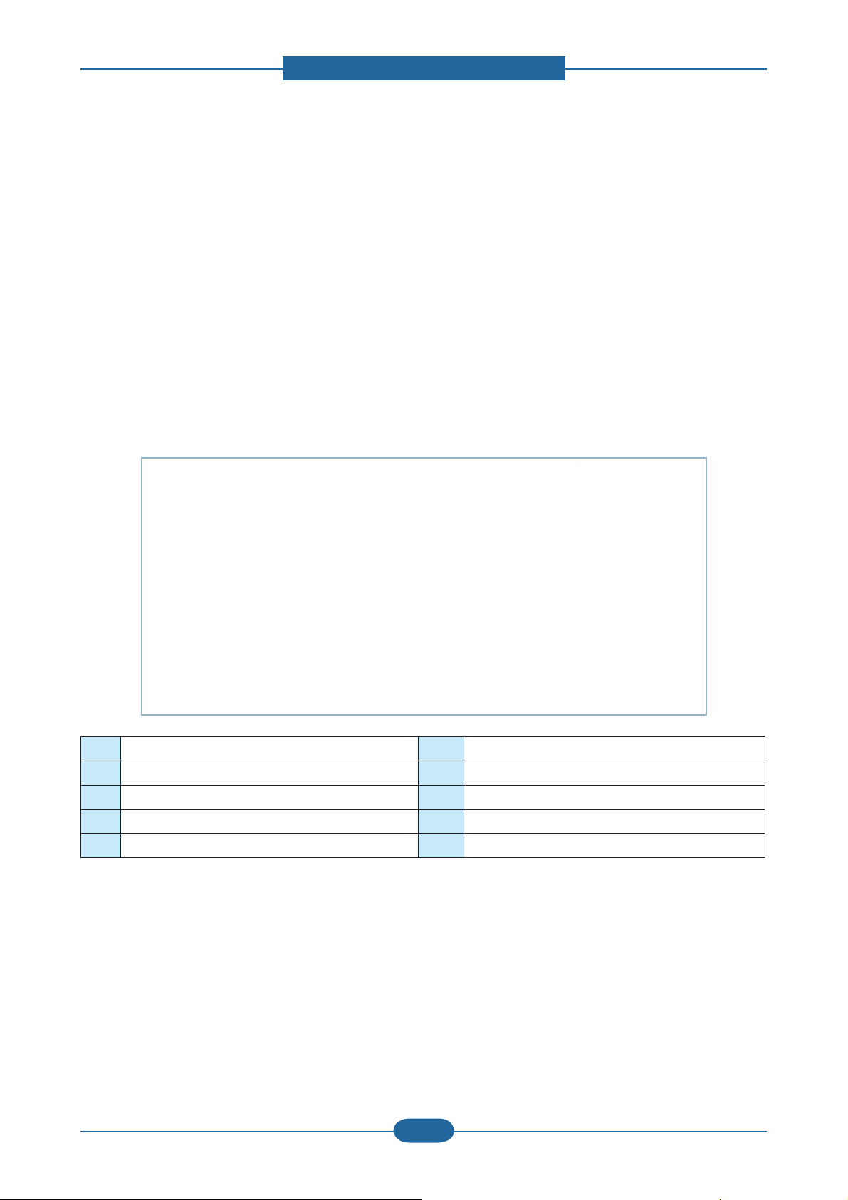
Circuit Board Locations
The following diagrams show the locations of the printer circuit boards:
WLAN
(Only SCX-573xFW)
FAX
HVPS
SMPS
Main Controller
Service Manual
SCX-483x/5x3x series
2-26
Samsung Electronics
Page 36

2. Product specifications and descriptions
2.2.5.1 Main controller
SCX-483xFD/HD Main Controller is composed with below components
-. CHORUS3 : To generate the printable video data and control engine
Embedded USB2.0 device
-. On board DDR2 SDRAM : system memory(128MB)
External DRR2 SO-DIMM : 256MB
-. Ethernet PHY : 10/100 Network printing
-. NOR Flash : 16MB for Program memory
-. Serial Flash: 8MB For Fax Data
The Main Controller manages an Electro-photography system, controls the Video Data of printing images
from Main Board to LSU, provides high-voltages and PWMs, adjusts temperature in the fusing system, reads
sensor signals and controls SCF option.
The Main controller also controls OPE and N/W PHY [Network], USB Device.
Rainier 31
Block Diagram
Ambient
THV readLD power
Fuser
thermistor
2010 .007. 12
1 BLDC
Engine (TBD)
- Solenoid ?
(MP,Pickup,Regi)
- Sens or ?
(Exit, Feed, Empty,
Regi,Out bin full , MP,
ADF_DET, ADF_POS,
ADF_COVER, Duplex)
- Fan (Main,
SMPS,MIDDLE)
DAC ADCRTC
Motor
PWM x 12
GPIO
H/ W
PROTECT
HVPS Board
(MHV,THV, DEV_DC
,FUSER_BIAS)
Cover S/W
RTC
battery
CPU: Chorus 3
Clock : 360Mhz
DDR2
control l er
DDR2 128M
ONBOARD +
256MB
1 DIMM
USB Device
SMPS(TYPE2)
24V, 5V, FDB, Relay
USB 2.0
ISP1582
Serial Flash (8M)
control l er
USB HOST
for FAX
SPI
LSU
LSU
2BEAM
UART x 4
5V
SMPS
Flash(16M)
Flash
I2C x 2
MAC
SCAN
IF / AFE
ST1S10
ST1S10
ST1S10
for OS
DCDC
DCDC
DCDC
[ Main Controller Diagram ]
3.3V
system
1.8V
1.0V
CHORUS 3
DDR
EEPROM(64K)
AC201A1KMLG
UR5596
ADF Unit
MAINBOARD
Power S/W
STEP
10/100
LAN
STEP
A3983
LAFE1001
CIS Scan Unit
PHY IC
0.9V
VTT
A3983
Modem
Conexant
OPE 2line
Buzzer , Power S/W
Debug
SCF
(Rst, Rx,Tx,REQ)
540?
NCRUM
Speaker
Home
Sensor
Service Manual
SCX-483x/5x3x series
2-27
Samsung Electronics
Page 37

2. Product specifications and descriptions
SCX-483xFD/HD Main Controller Printed Circuit Board Assembly
1 3
2
9 10 11
7
8
26
25
24
23
22
4 5 6
12
13
14
15
16
17181921 20
● Connection
1 USB HOST 14 N/W
2 FAX 15 USB Device
3 Outbin Full Sensor & Rear Cover 16 Parallel Option DC supply jack
4 CRUM 17 Exit Sensor
5 THERMISTOR 18 Air temp
6 FAN Middle 19 FAN SMPS
7 FAN Main 20 Main Motor & Clutch
8 HVPS 21 SCF
9 Paper Empty, Regi, Feed sensor 22 DDR2 Dimm
10 OPE 23 SMPS Signal
11 CIS 24 SMPS Power
12 ADF 25 MP
13 Scan Motor 26 LSU
● Information
- SEC-CODE : JC92-02351A
- PBA Name : PBA-MAIN
Service Manual
SCX-483x/5x3x series
2-28
Samsung Electronics
Page 38

2. Product specifications and descriptions
SCX-483xFR/563xFR/573xFW Main Controller is composed with below components
-. CHORUS4 : To generate the printable video data and control engine
Embedded USB2.0 device, Host channel
-. On board DDR2 SDRAM and external DDR2 SO-DIMM : system memory
On board DDR2 : 256MB
External DRR2 SO-DIMM : 512MB
-. Giga Ethernet PHY : Network printing
-. Nor Flash(32MB) : Program memory
-. Engine Controller(LEPC1) : ADC, DAC, Clutch, Fuser control
The Main Controller manages an Electro-photography system, controls the Video Data of printing images
from Main Board to LSU, provides high-voltages and PWMs, adjusts temperature in the fusing system, reads
sensor signals and controls SCF option.
The Main controller also controls OPE and Giga N/W PHY [Network], USB Device, Wireless Module.
o}wzGi
Oto}S{o}Skl}kj
Sm|zlyiphzP
jGzV~
l
TzGf
Otw SwSyP
l
TzGf
OlSGmSGlSG
ySvGGSGtwSG
hkmkl{SG hkmwvzSG
hkmjv}lySGkP
Tm
Ot S ztwz SGtpkks lP
sz| Yilht
XGiskj
ztwzO{wlYP
Y[}SG\} ztwzS
mkiSGy
skG
h
kkyYGY\]tG
vuivhykG
swljX
\XY tiGkp ttG
w~tGG[
nwpv
sz|G
t
oV~
wyv{lj{
24VS 1
24V 1
24V 2
ztwzO{wlZP
Y[}XSY[}YS G\}ztwzS
mkiSGy
{o}G
y{jG
R
kkyYG
y{j
CPU: Chorus[
Clock: ]WWMhz
DCDC
ST1S10
DCDC
5V
ST1S10
DCDC
ISL88550
5V
SMPS
A
m
mO ZYtP
|ziGYUWG
3.3V
system
1.1V
CHORUS 4
1.8V
DDR2
0.9V
VTT
Gvz
m
|zi
k
zwp
|hy{GG[
pYjGGY
thj
zjhu
pmGVGh ml
|ziGo|i
ns_\Wn
|ziGovz{OZP
Tmkp
T [nG|z iGmG
T kGw
thpuivhyk
Power S/W
OZYr iGG] [riP
PHY IC
RTL8211D
|ziGo|i
ns_\Wn
|ziGovz{OYP
T ~sh u
T [UZIG {m{Tsj k
SCX-4833FR,SC X-5637FR,SCX-5737FW
llwyvt
n
LAFE1001
hZ`_Z
shu
z{lw
Block Diagram V0.3
vwlMsjkGky}
i¡¡GSGwGzV~
tG
j
2010. 09.30
k
zjmG\[Wf
OySyS{SylxP
ujy| t
jpzGzG|
zGt OXP
hkmG|
zt Sz O[P
SjOZP
zjT[_ZZmy
zjT\]Z^my
zjT\^Z^m~
Rainier
z
oGz
[ssjk
[UZIG{m{Tsjk
rGw
i¡¡Sw GzV~
Service Manual
SCX-483x/5x3x series
[ Main Controller Diagram ]
2-29
Samsung Electronics
Page 39

2. Product specifications and descriptions
SCX-483xFR/563xFR/573xFW Main Controller Printed Circuit Board Assembly
● Connection
2
8
1
3 4 5 6
7
1 USB HOST
2 FAX
3 Paper Empty, Regi, Feed sensor
4 Out FULL SENSOR & Rear Cover
9
11
10
12
13
14
16
15
18 19
20
23
24
21
25
26 27
17
22
5 Fuser
6 CRUM
7 FAN Middle
8 HVPS
9 USB OPE
10 WLAN
11 OPE
12 CIS
13 DADF
14 FAN Main
15 LSU
16 Scan Motor
17 EDI
18 MP
19 Ethernet
20 SMPS Power
21 USB Device
22 Parallel Option DC supply jack
23 SMPS Signal
28
● Information
- SEC-CODE : JC92-02350B
- PBA Name : PBA-MAIN
Service Manual
SCX-483x/5x3x series
29
30
2-30
24 DDR2 SODIMM
25 Debug
26 Exit Sensor
27 FAN SMPS
28 SCF
29 Main Motor
30 Air temperature
Samsung Electronics
Page 40

2. Product specifications and descriptions
2.2.5.2 OPE Controller
The OPE Controller is composed of an OPE MICOM, two status LED, ECO LED, power LED,MODE LED
ANIMATION LED, WPS LED(SCX-573xFW model only), 16x2 line LCD(SCX-483xFD), 4Line LCD(SCX483xFR/563xFR), 4.3inch TFT LCD(SCX-573xFW), and some keys.
OPE communicates with main controller via UART/USB(SCX-573xFW).
Diagram of OPE Controller
OPE_TX
C P U
C P U
C P U
C P U
CHORUS3/
CHORUS3/
CHORUS3/
CHORUS3/
CHORUS4
CHORUS4
CHORUS4
CHORUS4
LCD DISPLAY
LCD DISPLAY
LCD DISPLAY
LCD DISPLAY
VHX1620BHRC9(2Line)
VHX1620BHRC9(2Line)
VHX1620BHRC9(2Line)
VHX1620BHRC9(2Line)
VHF12642(4Line)
VHF12642(4Line)
VHF12642(4Line)
VHF12642(4Line)
LMS430HF14(4.3inch TFT)
LMS430HF14(4.3inch TFT)
LMS430HF14(4.3inch TFT)
LMS430HF14(4.3inch TFT)
OPE_TX
OPE_RX
OPE_RX
OPE_RST
OPE_RST
USB
OPE MICOM
OPE MICOM
OPE MICOM
OPE MICOM
(STM8Sp103K3MAFTR)
(STM8Sp103K3MAFTR)
(STM8Sp103K3MAFTR)
(STM8Sp103K3MAFTR)
(S3C828B)
(S3C828B)
(S3C828B)
(S3C828B)
(S3C2415XH-40
(S3C2415XH-40
(S3C2415XH-40
(S3C2415XH-40
)
)
)
)
LED INDICATOR
LED INDICATOR
LED INDICATOR
LED INDICATOR
STATUS
STATUS
MODE
MODE
ANIMATION
ANIMATION
POWER
POWER
ECO
ECO
WPS
WPS
KEY INPUT
KEY INPUT
KEY INPUT
KEY INPUT
OPE Controller PBA
● Information
SEC-CODE : JC92-02352A•
PBA Name : PBA-OPE(2Line) •
for SCX-483xFD
● Information
SEC-CODE : JC92-02366A•
PBA Name : PBA-OPE(4Line)•
for SCX-483xFR/563xFR
● Information
SEC-CODE : JC07-00012A•
PBA Name : LCD(4Line)•
Service Manual
SCX-483x/5x3x series
2-31
Samsung Electronics
Page 41

2. Product specifications and descriptions
● Information
SEC-CODE : JC92-02324B•
PBA Name : PBA-OPE MAIN •
(GUI) for SCX-573xFW
● Information
SEC-CODE : JC07-00017A•
PBA Name : LCD (4.3 inch TFT)•
● Information
SEC-CODE : JC92-02365A•
PBA Name : PBA-OPE KEY •
SUB
2.2.5.3 WLAN (Only SCX-573xFW model)
The Wireless LAN Module supports 802.11b/g/n at only SCX-5737FW model via USB 2.0 high speed. The
Module is installed at the USB Host Channel of Main Controller PBA.
● Information
- SEC-CODE : JC92-02364A
- PBA Name : PBA-WNPC
Service Manual
SCX-483x/5x3x series
2-32
Samsung Electronics
Page 42

2. Product specifications and descriptions
2.2.5.4 SO-DIMM PBA - Optional
The SO-DIMM PBA is the system Memory module of the Main Controller. It is used for the operating system,
some system application programs, and it stores some print data from the USB and Network port. There are
two kinds of SO-DIMM PBA:
• 256MB capacity (SCX-483xFD)
● Information
- SEC-CODE : JC92-01975A 256MB
- PBA Name : PBA RAM DIMM
• 512MB capacity (SCX-483xFR/563xFR/573xFW)
● Information
- SEC-CODE : JC92-02087B 512MB
- PBA Name : PBA MAIN-DIMM
Service Manual
SCX-483x/5x3x series
2-33
Samsung Electronics
Page 43

2. Product specifications and descriptions
2.2.5.5 SCF PBA - Optional
The ADF SUB PBA(SCX-483xFD) is the Joint Board to Connect between ADF Module and Main board.
● Information
SEC-CODE : JC92-02387A
PBA Name : PBA-ADF
The JOINT PBA(SCX-483xFR/563xFR/573xFW) is the Joint Board to Connect between DADF Module and
Main board.
● Information
SEC-CODE : JC92-02353A
PBA Name : PBA-JOINT(DADF)
2.2.5.6 SCF PBA - Optional
The SCF PBA is the SCF control board. It use UART communication with main controller.
S3F443FX is used as a microcontroller.
● Information
SEC-CODE : JC82-00192A
PBA name : A/S ASSY-PBA SCF MAIN
Service Manual
SCX-483x/5x3x series
2-34
Samsung Electronics
Page 44

2. Product specifications and descriptions
2.2.5.7 CRUM PBA
CRUM PBA use I2C communication with main Controller.
● Information
SEC-CODE : JC92-02386A
PBA Name : PBA-TONER CRUM
2.2.5.8 Connection Part
Controller require connections to all of the system units such as the BLDC motor, Clutch, Sensor, and other
PBAs(OPE, HVPS, SMPS). The Main Controller contains various types of connectors, to deliver electronic
signals through signal wires. The signal wires provide electronic control signals that are used for starting and
stopping the motors, operating clutches, sensing the unit status, etc.
Service Manual
SCX-483x/5x3x series
2-35
Samsung Electronics
Page 45

2. Product specifications and descriptions
1
2
3
4
1
2
3
4
2.2.5.9 SMPS Board
The SMPS (Switching Mode Power Supply) Board supplies electric power to the Main Board and other
boards through a Main Controller. The voltage provided includes +5V, and +24V from a 110V/220V power
input.
SCX-483xFD/HD■
● Specification
General Input/Output Voltage
1) AC 110V (90V ~ 135V)
2) AC 220V (180V ~ 270V)
3) Output Current:
-.+5V : 1.6A
-.+24V : 1.8A
3) Output Power:
-.+5V : 8.16W
-.+24V : 43.2W
5) Heat Lamp Capacity : 850W
Service Manual
SCX-483x/5x3x series
● Information
110V 220V
SEC CODE JC44-00095D JC44-00096D
PBA NAME SMPS V1 SMPS V2
● Connection
1 INPUT_AC
2 Fuser_AC Output
3 SMPS Control Signal (from Engine PBA)
4 OUTPUT_5V&24V (to DC POWER PBA)
2-36
Samsung Electronics
Page 46

2. Product specifications and descriptions
SCX-483xFR/563xFR/573xFW■
2
3
4
● Specification
General Input/Output Voltage
1) AC 110V (90V ~ 135V)
2) AC 220V (180V ~ 270V)
3) Output Current:
-.+5V : 2.4A
-.+24V : 3.0A
4) Output Power:
-.+5V : 12W
-.+24V : 72W
5) Heat Lamp Capacity : 850W
1
● Information
110V 220V
SEC CODE JC44-00097E JC44-00090E
PBA NAME SMPS V1 SMPS V2
● Connection
1 INPUT_AC
2 Fuser_AC Output
3 SMPS Control Signal (from Engine PBA)
4 OUTPUT_5V&24V (to DC POWER PBA)
Service Manual
SCX-483x/5x3x series
2-37
Samsung Electronics
Page 47

2. Product specifications and descriptions
1
2 3 4 5
6
7
8
1
2 3 4 5
6
7
8
2.2.5.10 HVPS Board
The SCX-483x / 5x3x series contains a High Voltage Power Supply(HVPS) board.
This board generates high-voltage channels which includes MHV, DEV, BLADE, SUPPLY, OPC, THV and
FUSER BIAS.
● Connection
1 Main Interface 5 SUPPLY(-489V)
2 MHV(-1240V) 6 OPC(-51V)
3 DEV(-338V) 7 THV(+1315V, -1000V)
4 BLADE(-389V) 8 FUSER BIAS(240V)
● Information
- SEC-CODE : JC44-00197A
- PBA Name : HVPS
Service Manual
SCX-483x/5x3x series
2-38
Samsung Electronics
Page 48

2. Product specifications and descriptions
2.2.5.11 HVPS Board
The SCX-483x / 5x3x series contains a FAX board.The Modem Card is used to transfer and receive FAX
data through a telephone line. This PBA is controlled by the Main PBA and has two connectors, one for the
telephone line connection and the other for an external phone connection.
1
4
2
5
3
● Connection
1 Main Interface
2 Speaker
3 Hook(only China)
4 Tel Line
5 Ext Line
● Information
- SEC-CODE : JC92-01746A
: JC92-01746C (only China)
- PBA Name : SFX336 MODEM FAX MODULE
Service Manual
SCX-483x/5x3x series
2-39
Samsung Electronics
Page 49

2. Product specifications and descriptions
2.2.5.10 Electrical Parts Location
S7
S6
C3 M1
S5
C2
F1
F2
S3
C1
S2
S4
F3
S1
Sensor Part Description Part Code
M1 Main motor MOTOR BLDC JC31-00144A
C1 MP Pick up clutch CLUTCH-ELECTRIC JC47-00034A
C2 Cassette Pick up clutch CLUTCH-ELECTRIC JC47-00033A
C3 Regi clutch CLUTCH-ELECTRIC JC47-00033A
S1 Cassette paper empty sensor PHOTO-INTERRUPPTER 0604-001393
S2 MP paper empty sensor PHOTO-INTERRUPPTER 0604-001393
S3 Regi sensor PHOTO-INTERRUPPTER 0604-001393
S4 Feed sensor PHOTO-INTERRUPPTER 0604-001393
S5 Exit sensor PHOTO-INTERRUPPTER 0604-001393
S6 Outbin full sensor PHOTO-INTERRUPPTER 0604-001393
S7 Home position sensor PHOTO-INTERRUPPTER 0604-001415
F1 Middle fan FAN JC31-00146A
F2 Main fan FAN JC31-00146A
F3 SMPS fan FAN JC31-00108A
Service Manual
SCX-483x/5x3x series
2-40
Samsung Electronics
Page 50

2. Product specifications and descriptions
2.2.6 Engine F/W Control Algorithm
2.2.6.1 Feeding
If feeding from a cassette, the drive of the pickup roller is controlled by controlling the solenoid. The on/off
of the solenoid is controlled by controlling the general output port or the external output port. While paper
moves, occurrence of Jam is judged as below.
ITEM Description
- After picking up, paper cannot be entered because paper is not fed.
- After picking up, paper entered but it cannot reach to the feed sensor in certain time
JAM 0
JAM 1
due to slip, etc.
- After picking up, if the feed sensor is not on, re-pick up. After re-picking up, if the feed
sensor is not on after predetermined period of time, it is JAM 0.
- After the leading edge of the paper passes the feed sensor, the trailing edge of the
paper cannot pass the feed sensor after predetermined period of time.
- After the leading edge of the paper passes the feed sensor, the paper cannot reach
the exit sensor after predetermined period of time.
*The paper exists between the feed sensor and the exit sensor.
JAM 2
- After the trailing edge of the paper passes the feed sensor, the paper cannot pass the
exit sensor predetermined period of time.
2.2.6.2 Transfer
The charging voltage, developing voltage and the transfer voltage are controlled by PWM (Pulse Width
Modulation). The each output voltage is changeable due to the PWM duty. The transfer voltage admitted
when the paper passes the transfer roller is decided by environment conditions. The resistance value of the
transfer roller is changed due to the surrounding environment or the environment of the set, and the voltage
value, which changes due to the environments, is changed through AD converter. The voltage value for
impressing to the transfer roller is decided by the changed value.
Service Manual
SCX-483x/5x3x series
2-41
Samsung Electronics
Page 51

2. Product specifications and descriptions
2.2.6.3 Fusing
The temperature change of the heat roller’s surface is changed to the resistance value through the use of a
thermistor.
The Main Bd uses the resistance value of the Thermistor and converts it to a voltage value through the use
of an AD converter, the temperature is decided based on the voltage value read. The AC power is controlled
by comparing the target temperature to the value from the thermistor. If the value from the thermistor is out of
controlling range while controlling the fusing, the error stated in the below table occurs.
• Open Heat Error
When the engine operates the warm-up process, if the temperature of the fixing unit is not higher than a
specified temperature, the engine defines Open Heat Error. When this error is detected, the engine stops
all functions and keeps the error state. Also, the engine informs the error status of the main system, so it can
take appropriate action; and then the error message is displayed at LCD window or LED informing the error
status of the user.
• Low Heat Error
When the engine is at stand-by, printing or warm-up mode, if the temperature of the fixing unit is lower than
the specified temperature at each state and the lower temperature state is maintained during the specified
time, the engine defines Low Heat Error. When this error is detected, the engine stops all functions and
keeps it at the error state. Also, the engine informs the error status of the main system, so it can take
appropriate action; and then the error message is displayed at LCD window or LED informing the error status
of the user.
• Over Heat Error
For overall engine state, if the temperature of the fixing unit is higher than the specified temperature and the
temperature state is detected for a specific duration, then the engine defines Over Heat Error. When this
error is detected, the engine stops all functions and keeps it at the error state. Also, the engine informs the
error status of the main system, so it can take appropriate action; and then the error message is displayed at
LCD window or LED informing the error status of the user.
Service Manual
SCX-483x/5x3x series
2-42
Samsung Electronics
Page 52

2. Product specifications and descriptions
2.2.6.4 LSU
LSU receives the image data from PVC or HPVC and make the latent image on OPC surface.
It uses the single beam, LD. The errors related to LSU are as follows:
• By Lready
When the printing is started, the engine drives the polygon motor of LSU. After the specified time is elapsed,
if the motor is not in a ready status, the engine detects the error that the polygon motor is not in a ready
status. If this error happens, the engine stops all functions and keeps it at the error state. Also, the engine
informs the error status of the main system and the error message is displayed at LCD window to inform the
error status of the user.
• By Hsync
When the polygon motor is ready, the LSU sends out the signal called Hsync and used to synchronize with
each image line. So, if the engine does not detect consecutively the signal for a fixed time, it defines the
Hsync Error. If this error happens, the engine stops all functions and keeps it at the error state. Also, the
engine informs the error status of the main system and then the error message is displayed at LCD window
to inform the error status of the user. LSU Error Recovery: If the LReady or Hsync error happens, the paper
is exited before the error code is initiated. The engine mode is changed to recovery mode and the engine
informs the main system of the engine mode. And the engine checks the LSU error. If the error doesn’t
happen, the printing job.
Service Manual
SCX-483x/5x3x series
2-43
Samsung Electronics
Page 53

2. Product specifications and descriptions
2.2.7 S/W Descriptions
2.2.7.1 Overview
The software of SCX-483x/5x3x series system is constructed with
1) Host Software part that the application software operated in Window and Web Environment, and
2) Firmware parts that is a Embedded software controls printing job.
2.2.7.2 Architecture
Host Software is made up of
1. Graphic User Interface that offers the various editing functions to user in Host,
2. Driver that translates the received document to a Printing Command language which printer can
understand and transfers data to spooler,
Printer /MFP
Driver
HOST
Software
Web-based
Application
Stand-alone
Application
Application
(Emulation)
Firmware
Kernel
3. Stand-alone Application that offers the various printing application, PSU(Printer Settings Utility), Printer
Status Monitor, Network Management in Window system,
4. Web-based-Application that offers the same functions as Stand-alone Application and RDC(Remote
Diagnosis Control) in Web environment.
Firmware is made up of
1. Application (Emulation) that is a interpreter translate data received from Host to a printing language
(PCL, PS, GDI, etc.) to be able to make the user to take same output as originally one what composed in
Host.
2. Kernel that control and management the whole procedure include of Control flow and Printing Job before
transfer to Engine system.
Service Manual
SCX-483x/5x3x series
2-44
Samsung Electronics
Page 54

2. Product specifications and descriptions
2.2.7.3 Data and Control Flow
Host Firmware
Driver
USB
-PCL3, PS3
Web-based
- Document Management
System
- Network Administration
- Status Monitor
- Remote Control Panel
Stand-alone
- Printer Setting Utility
- Network Administration
- Status Monitor
The above Block Diagram is explained that:
3
R
U
W
0
R
Q
L
W
R
U
KERNEL
Engine
Network
Interface
Application
Application
(Emulation)
- PCL
- PS3
Host Side is made up of :
1. Driver that is Windows application software translate printed data to one of printer language and create
spooler file.
2. Web-based Application that offer a various printer additional functions, management of printing job,
printer administration, Status monitor to monitoring the printer status by real time in Web, independent
environment on OS.
3. Stand-alone Application that is a similar Window software as same as above 2,
4. Port Monitor that manages the network communication between spooler and Network Interface Card, or
various additional application and Network Interface Card,(this is, at first, make communication logical
port, manage the data, transfer them from spooler to network port, and offer the result of printing).
Service Manual
SCX-483x/5x3x series
2-45
Samsung Electronics
Page 55

2. Product specifications and descriptions
Firmware Side is made up of :
1. Network Interface Application is that relay the communication between Host and kernel using various
network protocol.
2. Kernel is that manages the flow control of emulation procedure, receiving data from Host or Network
application and printing with engine & rendering job,
3. Emulation is that interprets the various output data from selected emulation,
4. Engine is that prints rendered bit-map data to paper with required size and type by Kernel.
And then, for Job Spooling function for Multi-User, Multi-Printing that is occurred in Network printing and
various additional printing functions, this Kernel uses max. 10 Queuing systems in a memory.
In Printing, the two procedures are :
(1) Case of using USB Port
- After user start to print the wanted document to PCL string or compressed GDI bit-map data, Driver
translate the all graphic data of it and send data to host spooler. And then the spooler sends the data
stream to the printer via USB port.
- Kernel receives this data from Host, and then select emulation fit to data and start selected one. After
emulation job end, Kernel sends the output bit-map data to Engine using Printer Video Controller (by
clock type for LSU).
- Engine print the received data to required paper with the sequential developing process.
(2) Case of using Network Interface Application
- After user start to print the wanted document to PCL string or compressed GDI bit-map data, Driver
translate the all graphic data of it and send data to host spooler.
- If so, Port monitor managing network port receives data from spooler and sends a data stream to the
Network Interface Application.
- Network interface card receives it and send to Kernel part.
- Kernel receives this data from Host, and then select emulation fit to data and start selected one. After
emulation job end, Kernel sends the output bit-map data to Engine using Printer Video Controller (by
clock type for LSU).
- Engine print the received data to required paper with the sequential developing process.
Service Manual
SCX-483x/5x3x series
2-46
Samsung Electronics
Page 56

3. Disassembly and Reassembly
3. Disassembly and Reassembly
3.1 General Precautions on Disassembly
When you disassemble and reassemble
components, you must use extreme caution. The
close proximity of cables to moving parts makes
proper routing a must.
If components are removed, any cables disturbed
by the procedure must be restored as close as
possible to their original positions. Before removing
any component from the machine, note the cable
routing that will be affected.
Whenever servicing the machine, you
must perform as follows:
1. Check to verify that documents are not stored in
memory.
2. Be sure to remove the toner cartridge before you
disassemble parts.
3. Unplug the power cord.
4. Use a clean at surface.
5. Replace only with authorized components.
Releasing Plastic Latches
Many of the parts are held in place with plastic
latches. The latches break easily; release them
carefully.
To remove such parts, press the hook end of the
latch away carefully from the part to which it is
latched.
6. Do not force plastic-material components.
7. Make sure all components are in their proper
position.
Service Manual
SCX-483x/5x3x series
3-1
Samsung Electronics
Page 57

3. Disassembly and Reassembly
3.2 Screws used in the printer
The screws listed in the table below are used in this printer. Please ensure that, when you disassemble the
printer, you keep a note of which screw is used for which part and that, when reassembling the printer, the
correct screws are used in the appropriate places.
Part Code Location Description Qty
6003-000196
6003-000261 SCREW-TAPTYPE;BH,+,-,B,M3,L6,ZPC(WHT),SWRCH18A,- 2
6003-000269 SCREW-TAPTYPE;BH,+,-,S,M3,L6,ZPC(WHT),SWRCH18A,- 3
6002-000440 DUPLEX SCREW-TAPPING;PWH,+,2,M3,L8,ZPC(BLK),SWRCH18A 5
6003-000196 MP SCREW-TAPTYPE;PWH,+,B,M3,L10,NI PLT,SWRCH18A 2
6003-000196
6003-000269 SCREW-TAPTYPE;BH,+,-,S,M3,L6,ZPC(WHT),SWRCH18A,- 3
6003-000282 SCREW-TAPTYPE;BH,+,-,B,M3,L8,ZPC(BLK),SWRCH18A,- 4
6003-000269 DRIVE SCREW-TAPTYPE;BH,+,-,S,M3,L6,ZPC(WHT),SWRCH18A,- 6
6003-000196
6003-000261 SCREW-TAPTYPE;BH,+,-,B,M3,L6,ZPC(WHT),SWRCH18A,- 3
6003-000264 SCREW-TAPTYPE;PWH,+,-,B,M3,L6,ZPC(WHT),SWRCH18A,- 2
6003-000301 SCREW-TAPTYPE;BH,+,S,M4,L6,ZPC(WHT),SWRCH18A 1
6003-001474 SCREW-TAPTYPE;BH,+,B,M3,L30,ZPC(WHT),SWRCH18A 2
6006-001078 SCREW-TAPTYPE;PH,+,WSP,B,M3,L10,ZPC(WHT),SWRCH18A 1
6003-000282 LSU SCREW-TAPTYPE;BH,+,-,B,M3,L8,ZPC(BLK),SWRCH18A,- 5
6003-000196 COVER-MIDDLE SCREW-TAPTYPE;PWH,+,B,M3,L10,NI PLT,SWRCH18A 4
6003-000264 COVER-FRONT SCREW-TAPTYPE;PWH,+,-,B,M3,L6,ZPC(WHT),SWRCH18A,- 2
6003-000264 MP GUIDE-TRAY SCREW-TAPTYPE;PWH,+,-,B,M3,L6,ZPC(WHT),SWRCH18A,- 1
6003-000282 CARTRIDGE TONER SCREW-TAPTYPE;BH,+,-,B,M3,L8,ZPC(BLK),SWRCH18A,- 4
6003-000196 MFA SCREW-TAPTYPE;PWH,+,B,M3,L10,NI PLT,SWRCH18A 2
6003-000196
6003-000269 SCREW-TAPTYPE;BH,+,-,S,M3,L6,ZPC(WHT),SWRCH18A,- 4
6001-000130
6003-000196 SCREW-TAPTYPE;PWH,+,B,M3,L10,NI PLT,SWRCH18A 25
6003-000269 DRIVE-DADF SCREW-TAPTYPE;BH,+,-,S,M3,L6,ZPC(WHT),SWRCH18A,- 6
6003-000196 DADF-COVER OPEN SCREW-TAPTYPE;PWH,+,B,M3,L10,NI PLT,SWRCH18A 2
6001-000130 DADF-PLATEN SCREW-MACHINE;BH,+,M3,L6,ZPC(WHT),SWRCH18A 1
6003-000196 DADF-LOWER SCREW-TAPTYPE;PWH,+,B,M3,L10,NI PLT,SWRCH18A 2
6003-000196 DADF-UPPER SCREW-TAPTYPE;PWH,+,B,M3,L10,NI PLT,SWRCH18A 3
6003-000196 PLATEN SCREW-TAPTYPE;PWH,+,B,M3,L10,NI PLT,SWRCH18A 5
6003-000196 PLATEN-UPPER SCREW-TAPTYPE;PWH,+,B,M3,L10,NI PLT,SWRCH18A 4
6003-000196 PLATEN-LOWER SCREW-TAPTYPE;PWH,+,B,M3,L10,NI PLT,SWRCH18A 8
6003-000196 PLATEN-A4 MIDDLE SCREW-TAPTYPE;PWH,+,B,M3,L10,NI PLT,SWRCH18A 3
6003-000269 ELA UNIT-SCAN DRIVE SCREW-TAPTYPE;BH,+,-,S,M3,L6,ZPC(WHT),SWRCH18A,- 2
6003-000196 MAINLNE SCREW-TAPTYPE;PWH,+,B,M3,L10,NI PLT,SWRCH18A 20
FRAME MAIN
FUSER
FRAME-ETC
OPE
DADF
SCREW-TAPTYPE;PWH,+,B,M3,L10,NI PLT,SWRCH18A 20
SCREW-TAPTYPE;PWH,+,B,M3,L10,NI PLT,SWRCH18A 5
SCREW-TAPTYPE;PWH,+,B,M3,L10,NI PLT,SWRCH18A 38
SCREW-TAPTYPE;PWH,+,B,M3,L10,NI PLT,SWRCH18A 9
SCREW-MACHINE;BH,+,M3,L6,ZPC(WHT),SWRCH18A 1
Service Manual
SCX-483x/5x3x series
3-2
Samsung Electronics
Page 58

3. Disassembly and Reassembly
3.3 Disassembly procedure
3.3.1 Cover
1. Remove the cassette.
2. Remove the front cover by releasing both hooks.
3. Remove the duplex unit.
4. Open the rear cover and then remove it by
releasing both hooks.
Service Manual
SCX-483x/5x3x series
3-3
Samsung Electronics
Page 59

3. Disassembly and Reassembly
5. Remove the left cover. 6. Remove the right cover.
Service Manual
SCX-483x/5x3x series
3-4
Samsung Electronics
Page 60

3.3.2 Scanner Assy
3. Disassembly and Reassembly
1. Remove all covers. (Refer to 3.3.1)
2. Remove 5 screws. (Right x 1, Rear x 3, Front x 1)
3. Unplug 3 connectors.
4. Lift up and release the Scanner Assy.
Service Manual
SCX-483x/5x3x series
3-5
Samsung Electronics
Page 61

3.3.2.1 OPE board
3. Disassembly and Reassembly
1. Open the DADF unit.
2. Unplug the connector after removing the
connector cover.
3. Lift up and release the DADF unit.
4. Open the Scanner.
5. Remove 2 screws.
6. Turn up OPE Unit.
7. Unplug 2 connectors and remove 7 screws.
8. Release the OPE board.
Service Manual
SCX-483x/5x3x series
3-6
Samsung Electronics
Page 62

3.3.2.2 CIS Unit
3. Disassembly and Reassembly
1. Remove the DADF unit and OPE unit.
(Refer to 3.3.2.1)
2. Remove 5 screws.
3. Release the Platen glass unit.
4. Unplug the end of the at cable from the CIS,
and release the drive belt.
5. Remove the CIS Unit.
Service Manual
SCX-483x/5x3x series
3-7
Samsung Electronics
Page 63

3.3.2.3 Scan Motor
3. Disassembly and Reassembly
1. Remove the DADF unit, OPE unit and Platen
glass unit. (Refer to 3.3.2.1~2)
2. Remove 4 screws.
3.3.2.4 Home position sensor
3. Release the scan motor after removing 3 screws.
1. Remove the Platen glass unit. (Refer to 3.3.2.2)
2. Release the home position sensor after unplugging the connector.
Service Manual
SCX-483x/5x3x series
3-8
Samsung Electronics
Page 64

3. Disassembly and Reassembly
3.3.3 DADF Unit (SCX-563xFR / 563xHR / 573xFW)
1. Open the DADF unit.
2. Unplug the connector after removing the connector cover.
3. Lift up and release the DADF unit.
3.3.3.1 DADF Pick up unit
1. Remove the DADF-COVER OPEN. 2. Remove the spring. Release the shaft holder.
And then remove the DADF pick up unit.
Service Manual
SCX-483x/5x3x series
3-9
Samsung Electronics
Page 65

3.3.3.2 DADF board
3. Disassembly and Reassembly
1. Remove 4 screws.
2. Release the Original Feed Tray.
4. Remvoe the DADF rear cover.
5. Remove the DADF board after removing 2
screws and all harness.
3. Remove 3 screws.
Service Manual
SCX-483x/5x3x series
3-10
Samsung Electronics
Page 66

3.3.3.3 DADF Motor
3. Disassembly and Reassembly
1. Remove 8 screws.
2. Release the Original Feed Tray.
3. Remvoe the DADF rear cover.
4. Remove 2 screws.
Service Manual
SCX-483x/5x3x series
3-11
Samsung Electronics
Page 67

3. Disassembly and Reassembly
5. Remove the DADF front cover.
6. Remove 3 screws.
8. Remove 1 screw connecting the ground wire.
9. Release the DADF drive unit after removing 3
screws.
7. Remove 2 screws on DADF board.
Service Manual
SCX-483x/5x3x series
3-12
Samsung Electronics
Page 68

3. Disassembly and Reassembly
3.3.4 ADF Unit (SCX-483xFR/ FD/ HD)
1. Open the ADF unit.
2. Unplug the connector after removing the connector cover.
3. Lift up and release the ADF unit.
3.3.4.1 Tray Input
1. Open the ADF top cover.
2. Pull and release the rear hinge of the Original Feed Tray.
Service Manual
SCX-483x/5x3x series
3-13
Samsung Electronics
Page 69

3. Disassembly and Reassembly
3.3.4.2 Front / Rear cover
1. Remove 2 screws. 2. Remove the front and rear cover from both
sides.
3.3.4.3 Paper Path Assy
1. Remove the paper path Assy after removing 4 screws.
Service Manual
SCX-483x/5x3x series
3-14
Samsung Electronics
Page 70

3.3.4.4 ADF pick up unit
1. Remove 3 E-rings.
2. Pull the shaft to the direction of arrow.
3. Take off the ADF pick up unit.
3. Disassembly and Reassembly
3.3.4.5 ADF motor
1. Remove the paper path Assy after removing 4
screws.
2. Remove the motor after removing 2 screws.
Service Manual
SCX-483x/5x3x series
3-15
Samsung Electronics
Page 71

3.3.5 Middle Cover
3. Disassembly and Reassembly
1. Remove the Scanner Assy. (Refer to 3.3.2)
2. To remove the middle cover, remove 2 screws,
6 connectors,1 USB cable from the main board.
4. Release 2 hooks from the rear.
HookHook
5. Lift up and release the middle cover.
3. Remove 4 screws.
Service Manual
SCX-483x/5x3x series
3-16
Samsung Electronics
Page 72

3. Disassembly and Reassembly
3.3.6 Main board
1. Remove the right cover. (Refer to 3.3.1 Cover)
2. Unplug all connectors on the main board.
3. Remove 4 screws.
4. Release the main board.
3.3.7 HVPS board
1. Remove the right cover. (Refer to 3.3.1 Cover)
2. Remove 5 screws.
3. Unplug all connectors on the HVPS board.
4. Release the HVPS board.
Service Manual
SCX-483x/5x3x series
3-17
Samsung Electronics
Page 73

3. Disassembly and Reassembly
3.3.8 SMPS board
1. Remove the right cover. (Refer to 3.3.1 Cover)
2. Unplug all connectors on the SMPS board.
3. Remove 4 screws.
4. Release the SMPS board.
3.3.9 Laser Scanning Unit (LSU)
1. Remove the Middle cover. (Refer to 3.3.5 Middle Cover)
2. Unplug 2 at cables from the LSU.
3. Remove 3 screws.
4. Release the LSU.
Service Manual
SCX-483x/5x3x series
3-18
Samsung Electronics
Page 74

3. Disassembly and Reassembly
3.3.10 Fuser unit
CAUTION
The temperature gets high in the vicinity of the fuser unit. When replacing it, you may get injured. Before
replacing it, make sure that fuser unit has cooled.
1. Open the Frame-Rear by pushing both green
points.
Frame-RearFrame-Rear
2. Remove the Frame-Rear by releasing both
hooks.
3. Remove the exit sensor holder after removing
2 screws.
4. Remove 4 screws.
CAUTION
When reassembling the fuser unit, do not forget to
tighten these screws.
5. Release the fuser unit.
Exit sensor holderExit sensor holder
Service Manual
SCX-483x/5x3x series
3-19
Samsung Electronics
Page 75

3.3.11 Main drive unit
3. Disassembly and Reassembly
1. Remove the left cover. (Refer to 3.3.1 Cover)
2. Remove the Bar coupler.
Bar couplerBar coupler
3. Remove the main drive unit after removing
6 screws.
5
5
4. Unplug the connector from the main motor.
5. Release the main drive unit.
1
1
3
3
6
4
4
2
2
6
NOTE
When reassembling the main drive unit, tighten 6
screws in order as shown above.
Service Manual
SCX-483x/5x3x series
3-20
Samsung Electronics
Page 76

3. Disassembly and Reassembly
3.3.12 Feed drive unit
1. Remove the main drive unit. (Refer to 3.3.11)
2. Release the feed drive unit after removing 2 screws.
3.3.13 Pick up/ Regi/ MP clutch
1. Remove the feed drive unit.
2. For the clutch to require replacement, unplug the connector then replace it.
Regi.
Pick-up
Pick-up
MPRegi.
MP
Service Manual
SCX-483x/5x3x series
3-21
Samsung Electronics
Page 77

3. Disassembly and Reassembly
3.3.14 Pick up roller
1. Remove the cassette and duplex unit.
2. Pull the small tap down, then release the pick up roller.
2
121
3.3.15 Transfer roller
1. Remove the top cover.
(Refer to 3.3.5 Middle Cover)
2. Release the LSU bracket after removing
4 screws.
3. Push the transfer roller holder to the center and
release it.
4. Remove the transfer roller.
Transfer rollerTransfer roller
Service Manual
SCX-483x/5x3x series
3-22
Samsung Electronics
Page 78

3.3.16 MP unit
3. Disassembly and Reassembly
1. Remove the front / middle / right cover.
2. Remove 4 screws.
3.3.17 Bin-full sensor
3. Separate the MP lower from the MP upper.
MP pick up/ forward roller
MP pick up/ forward roller
MP retard roller
MP retard roller
1. Remove the top / left cover.
2. Release the bin-full sensor after unplugging the connector.
Service Manual
SCX-483x/5x3x series
3-23
Samsung Electronics
Page 79

3. Disassembly and Reassembly
3.3.18 Regi. / Feed / Empty sensor
1. Remove the cassette and duplex unit.
2. Remove the PLATE-FRAME BOTTOM after
removing 4 screws.
3. Remove the sensor cover after removing 2
screws.
4. For the sensor to require replacement, unplug
the connector then replace it.
Regi. sensor
Regi. sensor
Feed sensor
Feed sensor
5. Remove the sensor cover after removing
2 screws.
Service Manual
SCX-483x/5x3x series
3-24
Samsung Electronics
Page 80

3. Disassembly and Reassembly
6. Unplug the connector then release the empty
sensor.
Empty sensorEmpty sensor
3.3.19 Cassette roller (Retard roller)
1. Remove the cassette.
2. Open the COVER-CASSETTE.
3. Release the Retard roller.
Service Manual
SCX-483x/5x3x series
3-25
Samsung Electronics
Page 81

4. Alignment and Troubleshooting
4. Alignment and Troubleshooting
4.1 Alignment and Adjustments
This chapter describes the main functions for service, such as the product maintenance method, the test
output related to maintenance and repair, Jam removing method, and so on.
It includes the contents of manual.
4.1.1 Control Panel
■ Type A
Y
X
Z \ ^[ ] _ XW` XY XZXX
YW
1 Darkness
2 ID Copy
3 Display screen Shows the current status and prompts during an operation.
4 Copy Activates Copy mode.
5 Fax Activates Fax mode.
6 Left/Right Arrows
7 Menu Enters Menu mode and scrolls through the available menus.
8 OK Con rms the selection on the screen.
9 Numeric keypad Dials a number or enters alphanumeric characters.
10 Address Book
Adjusts the brightness level to make a copy for easier reading, when the
original contains faint markings and dark images.
Allows you to coy both sides the ID card like a driver’s license to a single
side of paper.
Scrolls through the options available in the selected menu and increases
or decreases values.
Allows you to store frequently used fax numbers and email addresses or
search for stored fax numbers or email addresses.
X[X\X]X^X_ ]X`
Service Manual
SCX-483x/5x3x series
4-1
Samsung Electronics
Page 82

4. Alignment and Troubleshooting
11 Redial/Pause
Redials the last number in ready mode, or inserts a pause into a fax
number in Edit mode.
12 Stop/Clear Stops an operations at any time.
Turn the power on or off, or wake up the machine from the power save
13 Power
mode. Press this button until Power Down appears on the display and
choose Yes to turn the power off. You can also turn the power on, or wake
up the machine from power save mode by pressing this button.
14 Status LED Shows the status of your machine.
15 Start Starts a job.
16 On Hook Dial
When you press this button, you can hear a dial tone. Then enter a fax
number. It is similar to making a call using speaker phone.
17 Back Sends you back to the upper menu level.
18 Scan Activates Scan mode.
19 Eco Turn into eco mode to reduce toner consumption and paper usage.
20 Direct USB
Allows you to directly print les stored on a USB memory device when it is
inserted into the USB port on the front of your machine.
Service Manual
SCX-483x/5x3x series
4-2
Samsung Electronics
Page 83

■ Type B
4. Alignment and Troubleshooting
Y
X
Z \ ][ ^ ` XX XYXW_
YW
1 Darkness
2 ID Copy
X`
Adjusts the brightness level to make a copy for easier reading, when the
original contains faint markings and dark images.
Allows you to coy both sides the ID card like a driver’s license to a single
side of paper.
X^
3 Display screen Shows the current status and prompts during an operation.
4 Copy Activates Copy mode.
5 Fax Activates Fax mode.
6 Arrows
Scroll through the options available in the selected menu, and increase or
decrease values.
7 OK Con rms the selection on the screen.
8 Numeric keypad Dials a number or enters alphanumeric characters.
9 Address Book
10 Redial/Pause
Allows you to store frequently used fax numbers and email addresses or
search for stored fax numbers or email addresses.
Redials the last number in ready mode, or inserts a pause into a fax
number in Edit mode.
XZX[X\X_ ]X]
11 Stop/Clear Stops an operations at any time.
Turn the power on or off, or wake up the machine from the power save
12 Power
mode. Press this button until Power Down appears on the display and
choose Yes to turn the power off. You can also turn the power on, or wake
up the machine from power save mode by pressing this button.
13 Status LED Shows the status of your machine.
14 Start Starts a job.
15 On Hook Dial
When you press this button, you can hear a dial tone. Then enter a fax
number. It is similar to making a call using speaker phone.
16 Back Sends you back to the upper menu level.
Service Manual
SCX-483x/5x3x series
4-3
Samsung Electronics
Page 84

4. Alignment and Troubleshooting
17 Menu Enters Menu mode and scrolls through the available menus.
18 Scan Activates Scan mode.
19 Eco Turn into eco mode to reduce toner consumption and paper usage.
20 Direct USB
Allows you to directly print les stored on a USB memory device when it is
inserted into the USB port on the front of your machine.
Service Manual
SCX-483x/5x3x series
4-4
Samsung Electronics
Page 85

■ Type C
4. Alignment and Troubleshooting
X Z [
Y
XW
1 Display screen Shows the current status and prompts during an operation.
2 Numeric keypad Dials a number or enters alphanumeric characters.
3 Clear Deletes characters in the edit area.
4 Stop Stops an operations at any time.
Turn the power on or off, or wake up the machine from the power save
5 Power
mode. Press this button until Power Down appears on the display and
choose Yes to turn the power off. You can also turn the power on, or wake
up the machine from power save mode by pressing this button.
\
]^_XX `
6 WirelessLED Shows the current status of the wireless network connection.
7 Status Shows the status of your machine.
8 Start Starts a job.
9 Log out Allows user to log out.
10 Help Gives detailed information about this machine’s menus or status.
11 Reset Resets the current machine’s setup.
Service Manual
SCX-483x/5x3x series
4-5
Samsung Electronics
Page 86

4. Alignment and Troubleshooting
4.1.2 Understanding The Status LED
The color of the Status indicates the machine’s current status.
NOTE
• Some LEDs may not be available depending on model or country.
• To resolve the error, look at the error message and its instructions from the troubleshooting part.
STATUS DESCRIPTION
Status
LED
Wireless
b
LED
Off • The machine is off-line.
Green Blinking • When the backlight slowly blinks, the machine is receiving data from
the computer.
• When the backlight blinks rapidly, the machine is printing data.
On • The machine is on-line and can be used.
Red Blinking • A minor error has occurred and the machine is waiting for the error
to be cleared. Check the display message. When the problem is
cleared, the machine resumes. For some models that does not
support the display screen on the control panel, this feature is not
applicable.
• Small amount of toner is left in the cartridge. The estimated cartridge
life of toner is close. Prepare a new cartridge for replacement. You
may temporarily increase the printing quality by redistributing
the toner
On • A toner cartridge has almost reached its estimated cartridge life
a
.
• The cover is opened. Close the cover.
• There is no paper in the tray. Load paper in the tray.
• The machine has stopped due to a major error.
Blue On When the machine is connected to a wireless network, Wireless LED
lights on blue.
a. Estimated cartridge life means the expected or estimated toner cartridge life, which indicates the average capacity
of print-outs and is designed pursuant to ISO/IEC 19752. The number of pages may be affected by operating
environment, printing interval, graphics, media type and media size. Some amount of toner may remain in the cartridge
even when red LED is on and the printer stops printing.
b. Wireless model only
Service Manual
SCX-483x/5x3x series
4-6
Samsung Electronics
Page 87

4. Alignment and Troubleshooting
4.1.3 JAM Removal
4.1.3.1 Clearing original document jams
To avoid tearing the document, remove the jammed document slowly and carefully.
Original paper jam in front of scanner
1. Remove any remaining pages from the
document feeder.
2. Open the document feeder cover.
3. Gently remove the jammed paper from the
document feeder.
4. Close the document feeder cover.
Service Manual
SCX-483x/5x3x series
4-7
Samsung Electronics
Page 88

4. Alignment and Troubleshooting
Original paper jam inside of scanner
1. Remove any remaining pages from the
document feeder.
2. Open the document feeder cover.
3. Gently remove the jammed paper from the
document feeder.
4. Open the document feeder.
5. Grasp the misfeed paper, and remove the paper
from the feed area by carefully pulling it.
If you see no paper in this area, go to next step.
Service Manual
SCX-483x/5x3x series
6. Close the document feeder.
4-8
Samsung Electronics
Page 89

4. Alignment and Troubleshooting
Original paper jam in exit area of scanner
1. Remove any remaining pages from the
document feeder.
2. Gently remove the jammed paper from the
document feeder.
Original paper jam in scanner duplex path
NOTE - For SCX-4833FR, SCX-4835FR, SCX563x Series and SCX-573x Series.
1. Remove any remaining pages from the
document feeder.
2. Open the document feeder cover.
3. Open the duplex jam cover.
Service Manual
SCX-483x/5x3x series
4-9
Samsung Electronics
Page 90

4. Alignment and Troubleshooting
4. Pull the jammed paper gently out of the
document feeder.
Close the duplex jam cover and the document
feeder cover. If you do not see paper in this area,
go to the next step.
6. Grasp the misfeed paper, and remove the paper
from the feed area by carefully pulling it.
7. Close the document feeder.
5. Open the document feeder.
Service Manual
SCX-483x/5x3x series
4-10
Samsung Electronics
Page 91

4. Alignment and Troubleshooting
4.1.3.2 Clearing paper jams
To avoid tearing the paper, pull the jammed paper out slowly and gently.
In tray1
1. Open and close the front cover. The jammed
paper is automatically ejected from the machine.
If the paper does not exit, go to the next step.
2. Pull out tray1.
4. Insert tray 1 back into the machine until it snaps
into place. Printing automatically resumes.
In optional tray2
1. Pull out optional tray 2.
2. Remove the jammed paper from the machine.
3. Remove the jammed paper by gently pulling it
straight out.
If the paper does not move when you pull, or if you
do not see the paper in this area, check the fuser
area around the toner cartridge.
If the paper does not move when you pull or if you
do not see the paper in this area, stop and go to
the next step.
3. Pull tray1 half-way out.
Service Manual
SCX-483x/5x3x series
4-11
Samsung Electronics
Page 92

4. Alignment and Troubleshooting
4. Pull the paper straight up and out.
5. Insert the trays back into the machine. Printing
automatically resumes.
Inside the machine
1. Open the front cover and pull the toner cartridge
out.
3
2. Remove the jammed paper by gently pulling it
straight out.
In the multi-purpose tray
1. If the paper is not feeding properly, pull the
paper out of the machine.
2. Open and close the front cover to resume
printing.
3. Replace the toner cartridge and close the front
cover. Printing automatically resumes.
Service Manual
SCX-483x/5x3x series
4-12
Samsung Electronics
Page 93

4. Alignment and Troubleshooting
In the exit area
1. Open and close the front cover. The jammed
paper is automatically ejected from the machine.
If you do not see the jammed paper, go to the
next step.
2. Gently pull the paper out of the output tray.
In the duplex unit area
1. Pull the duplex unit out of the machine.
2. Remove the jammed paper from the duplex unit.
If you do not see the jammed paper or if there is
any resistance when you pull, stop and go to the
next step.
3. Open the rear cover.
4. Remove the jammed paper as shown in the
following gure.
3
3
If the paper does not come out with the duplex unit,
remove the paper from the bottom of the machine.
If you still do not see the paper, go to the next step.
5. Close the rear cover. Printing automatically
resumes.
Service Manual
SCX-483x/5x3x series
4-13
Samsung Electronics
Page 94

4. Alignment and Troubleshooting
3. Insert the duplex unit into the machine.
4. Open the rear cover.
5. Remove the jammed paper as shown in the
following gure.
3
3
6. Return the fuser door and the lever to their
original position.
7 Close the rear cover. Printing automatically
resumes.
Service Manual
SCX-483x/5x3x series
4-14
Samsung Electronics
Page 95

4. Alignment and Troubleshooting
4.1.4 Useful menu item for service
a) Monitoring the supplies life.
If you experience frequent paper jams or printing problems, check the number of pages the machine has
printed or scanned. Replace the corresponding parts, if necessary.
NOTE - Accessing menus may differ from model to model
1. Select Menu > System Setup > Maintenance > Supplies Life on the control panel.
2. Select the option you want and press OK.
• Supplies Info: Prints the supply information page.
• Total: Displays the total number of pages printed.
• ADF Scan: Displays the number of pages printed by using the document feeder.
• Platen Scan: Displays the number of pages scanned by using scanner glass.
3 Press (Stop/Clear) to return to ready mode.
b) Printing a report
This product provides several printable reports for maintenance purposes.
These reports can be used to aid the diagnosis of print quality problems.
■ Configuration report (Menu > System Setup > Report > Configuration)
You can print a report on the machine’s overall con guration. It shows various SW version and current
machine setting status.
■ Supplies Information report (Menu > System Setup > Report > Supplies Info.)
You can print supplies’ information page. It shows consumable unit life status and toner using status.
■ Usage Counter (Menu > System Setup > Report > Usage Counter)
You can print a usage page. The usage page contains the total number of pages printed.
c) Maintenance menu
This menu allows you to maintain your machine. (Menu > System setup > Maintenance)
• CLR Empty Msg. : This option appears only when toner cartridge is empty.
• Supplies Info. : This item allows you to check how many pages are printed and how much toner are left in
the cartridge.
• TonerLow Alert : If toner in the cartridge has run out, a message informing user to change the toner
cartridge appears. You can set the option for this message to appear or not.
Service Manual
SCX-483x/5x3x series
4-15
Samsung Electronics
Page 96

4. Alignment and Troubleshooting
d) Altitude adjustment
The print quality is affected by atmospheric pressure, which is determined by the height of the machine
above sea level. The following information will guide you on how to set your machine to the best print quality
or best quality of print.
Before you set the altitude value, determine the altitude where you are.
4,000 m
(13,123 ft)
1
3,000 m
(9,842 ft)
2
2,000 m
(6,561 ft)
3
4
1 High 3
2 High 2
3 High 1
4 Normal
1,000 m
(3,280 ft)
0
1. Ensure that you have installed the printer driver with the provided Printer Software CD.
2. Double-click the Smart Panel icon on the Noti cation Area in Linux. You can also click Smart Panel on
the status bar in Mac OS X.
For Windows user, select Start > Programs or All Programs > Samsung Printers > Samsung Easy
Printer Manager.
3. Click Printer Setting.
If your machine is connected to the network, you can set the altitude via SyncThru™ Web Service.
4. Click Setting > Altitude Adjustment. Select the appropriate value from the drop-down list, and then click
Apply.
You can also set the altitude in System Setup > Altitude Adj. option on the machine’s display.
Service Manual
SCX-483x/5x3x series
4-16
Samsung Electronics
Page 97

4. Alignment and Troubleshooting
1
3
8
2
7
4
6
5
4.1.5 Periodic Defective Image
If an image defects appears at regular intervals on the printed-paper, it is due to a faulty or damaged roller.
Refer to the table below and check the condition of the appropriate roller.
No Roller Description
Band Period
(mm)
Phenomenon Defective part
1 1st Pressure roller 62.8 mm Background
3 Heat roller 77.8 mm Black spot and fuser ghost
4 Charge roller 26.7 mm Black spot
5 Developer roller 36.78 mm Horizontal band
6 OPC drum 75.49 mm White and Black spots
7 Supply roller 69.57 mm Horizontal band
8 Transfer roller 47.1 mm Ghost, Damaged image
Service Manual
SCX-483x/5x3x series
4-17
Fuser unit2 2nd Pressure roller 37.7 mm Background
Toner cartridge
Samsung Electronics
Page 98

4. Alignment and Troubleshooting
4.1.6 Using the Samsung Easy Printer Manager program and Smart Panel
Samsung Easy Printer Manager and Smart Panel are a program that monitors and informs you of the
machine status, and allows you to customize the machine’s settings. These programs are installed
automatically when you install the machine software.
To use this program, you need the following system requirements:
• Windows. Check for windows operating system(s) compatible with your machine.
• Mac OS X 10.3 or higher
• Linux. Check for Linux systems that are compatible with your machine.
• Internet Explorer version 5.0 or higher for ash animation in HTML Help.
If you need to know the exact model name of your machine, you can check the supplied software CD.
4.1.6.1 Using the Samsung Easy Printer Manager program (Windows only)
Samsung Easy Printer Manager is a Windows-based application that combines Samsung device settings into
one location. Samsung Easy Printer Manager combines device settings as well as printing environments,
settings/actions, launching applications, and so on. All of these features provide a gateway to conveniently
use Samsung machine. Samsung Easy Printer Manager provides two different user interfaces for the user to
choose from: the default user interface and the advanced settings user interface. Switching between the two
interfaces is easy: just click a button.
Understanding Samsung Easy Printer Manager program
This interface is intended to be used by general device users in a small business or small home of ce
environment.
For Windows user, select Start > Programs or All Programs > Samsung Printers > Samsung Easy Printer
Manager.
The Samsung Easy Printer Manager interface is comprised of various basic sections as described in the
table that follows.
Service Manual
SCX-483x/5x3x series
4-18
Samsung Electronics
Page 99

4. Alignment and Troubleshooting
1 Printer List
The Printer List displays icons corresponding to discovered network or local
printers’ error status.
This area gives you general information about your machine. You can check
information, such as the machine’s model name, IP address (or Port name),
and machine status.
2 Printer Information
Troubleshooting button: This button opens Troubleshooting Guide when
an error occurs. You can directly open the necessary section in the user’s
guide.
Application
3
information
Includes links for changing to the advanced settings, preference, help, and
about.
Displays Quick links to machine speci c functions. This section also includes
links to applications in the advanced settings.
4 Quick links
If you connect your machine to a network, the SyncThru™ Web Service
window appears.
Displays information about the selected machine, remaining toner level
5 Contents Area
and paper. The information will vary based on the machine selected. Some
machines do not have this feature.
6 Order Supplies
Click on the Order button from the supply ordering window. You can order
replacement toner cartridge(s) from online.
Click the Help button from the upper-right corner of the window and click on any option you want to know
about.
4.1.6.2 Using the Smart Panel program (Macintosh and Linux only)
Smart Panel is a program that monitors and informs you of the machine’s status, and allows you to customize
the machine’s settings. For Macintosh, Smart Panel is installed automatically when you install the machine
software. For Linux, you can download Smart Panel from the Samsung website.
Smart Panel overview
GY
Z
[
X
You can view the level of toner remaining in each toner cartridge. The
1 Toner Level
machine and the number of toner cartridge(s) shown in the above window
may differ depending on the machine in use. Some machines do not have
this feature.
2 Buy Now You can order replacement toner cartridge(s) from online.
3 User’s Guide You can view the online User’s Guide.
4 Printer Setting
Service Manual
SCX-483x/5x3x series
You can con gure various machine settings in the Printer Settings Utility
window. Some machines do not have this feature.
4-19
Samsung Electronics
Page 100

4. Alignment and Troubleshooting
4.1.7 Updating Firmware
This chapter includes instructions for updating the printer rmware. You can update the printer rmware by
using one of the following methods :
• Update the rmware by using the USB port.
• Update the rmware by using the network.
4.1.7.1 Update the firmware by using the USB port
[Upgrading preparations]
- usblist2.exe : Tool which sends rmware data to printer.
- Firmware le to upgrade
[Upgrade Procedure]
1. Turn the machine off.
2. Connect USB cable to printer.
3. Turn the machine on. Check if the printer is the ready status.
4. Drag the rmware le and Drop down on the usblist2.exe.
And then rmware update will be started automatically.
5. When upgrading is completed, machine is automatically re-booting.
Service Manual
SCX-483x/5x3x series
4-20
Samsung Electronics
 Loading...