

Samsung SCX-1150F Disassemble

When you disassemble and reassemble components, you
must use extreme caution.
The close proximity of cables to moving parts makes proper routing a must. If components are removed or replaced,
any cables disturbed by the procedure must be replaced as
close as possible to their original positions.
Before removing any component from the machine, note
the cable routing that will be affected.
Whenever servicing the machine, you must perform as
follows:
1. Check to verify that documents are not stored in memory.
2. Unplug the power cord.
3. Use a flat and clean surface.
4. Replace only with authorized components.
5. Do not force to remove or planten plastic-material components.
6. Make sure all components are in their proper position.
3-1
Samsung Electronics
3. Disassembly and Reassembly
3-1 General Precautions on Disassembly
Disassembly and Reassembly
3-2
Samsung Electronics
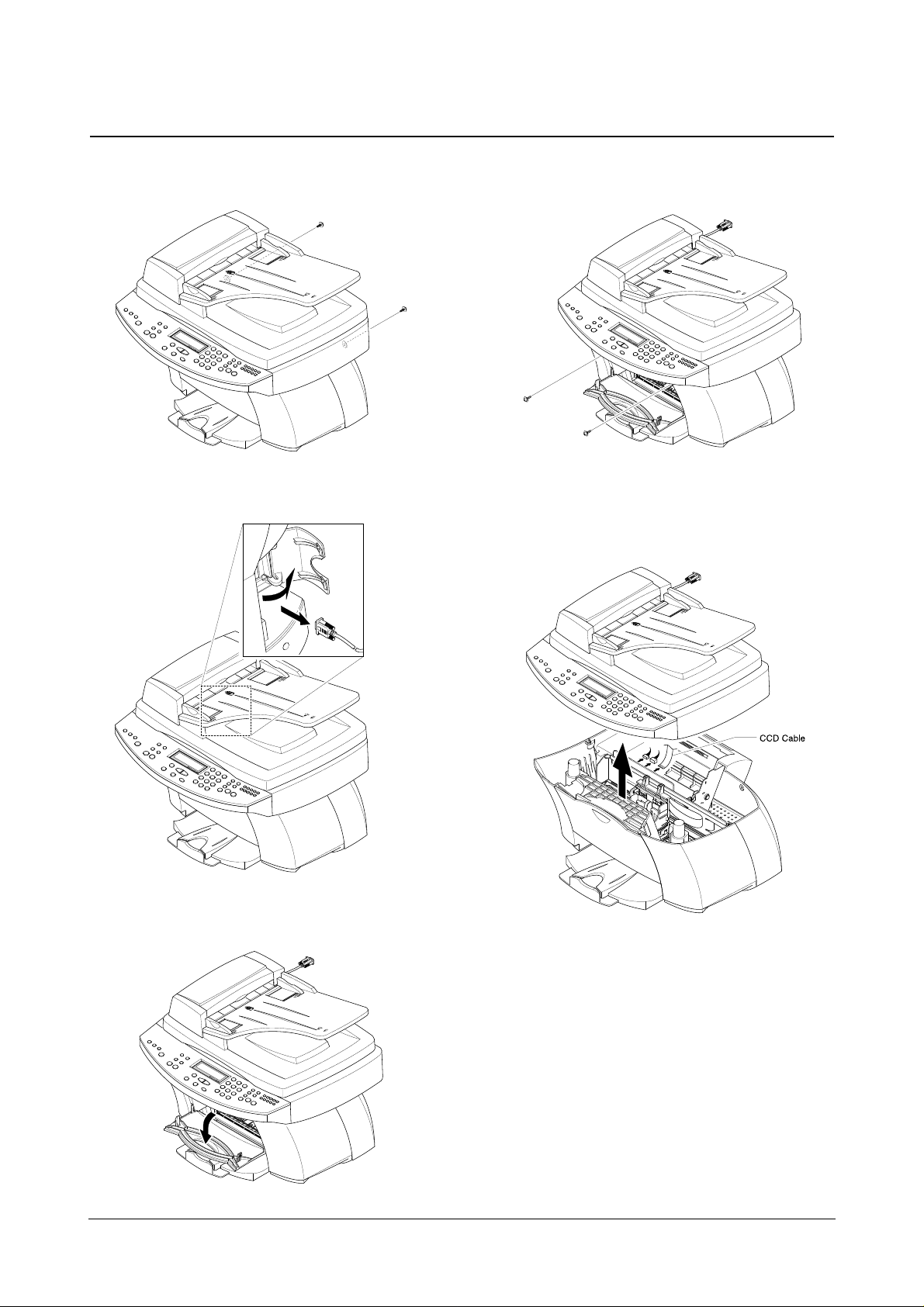
3-2 Scanner ASS’Y
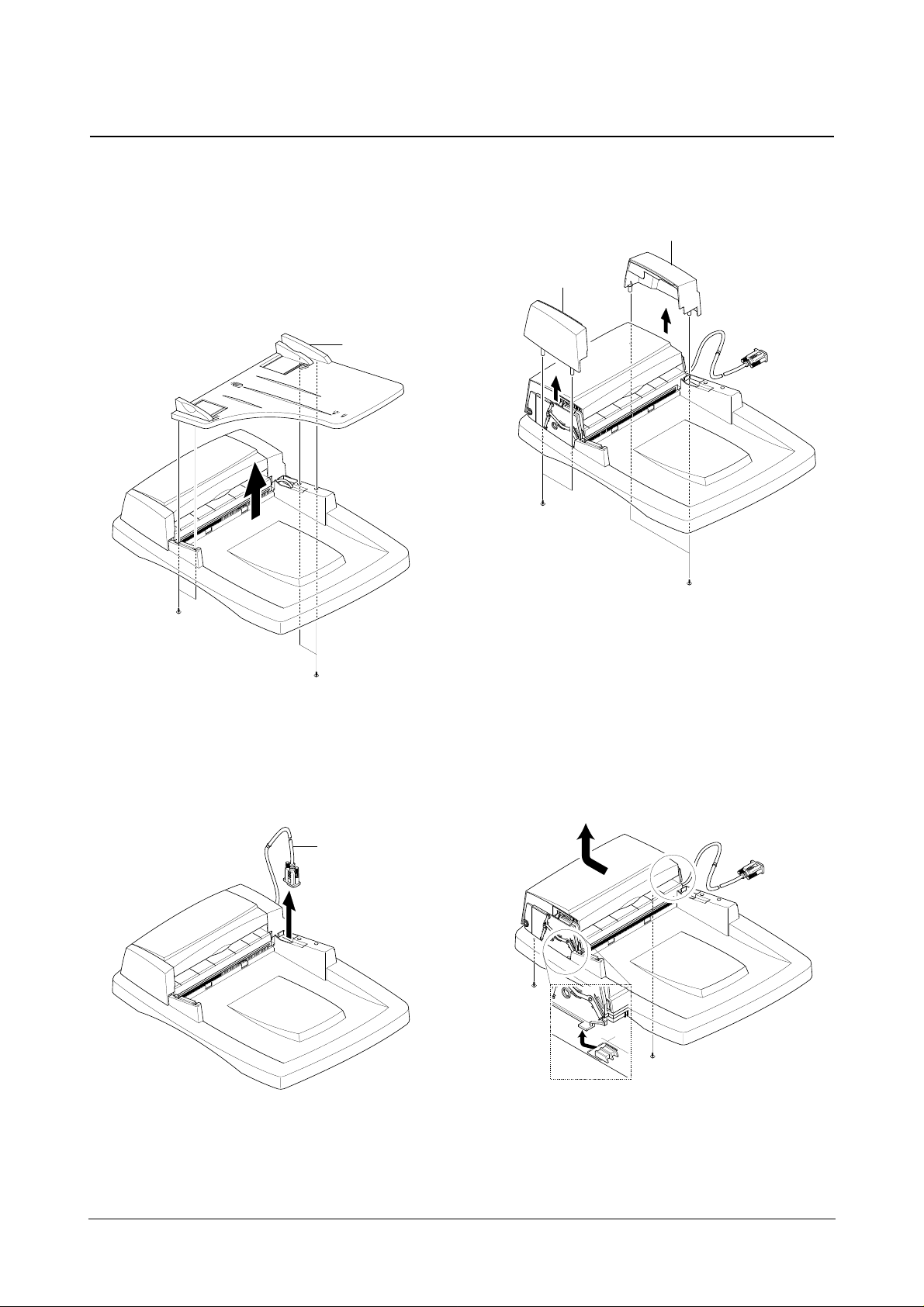
1. Remove two screws securing the Rear Cover.
2. Open the Side Door and remove the ADF Connector,
as shown below.
3. Open the Front Door from the Main Cover.
4. Remove two screws securing the Main Cover.
5. Pull the Scanner ASS’Y upward then, unplug the two
connectors and the CCD Cable.
♦ You should connect or remove the CCD Cable vertically to
avoid the CCD Cable pin damage.
Disassembly and Reassembly
3-3
Samsung Electronics
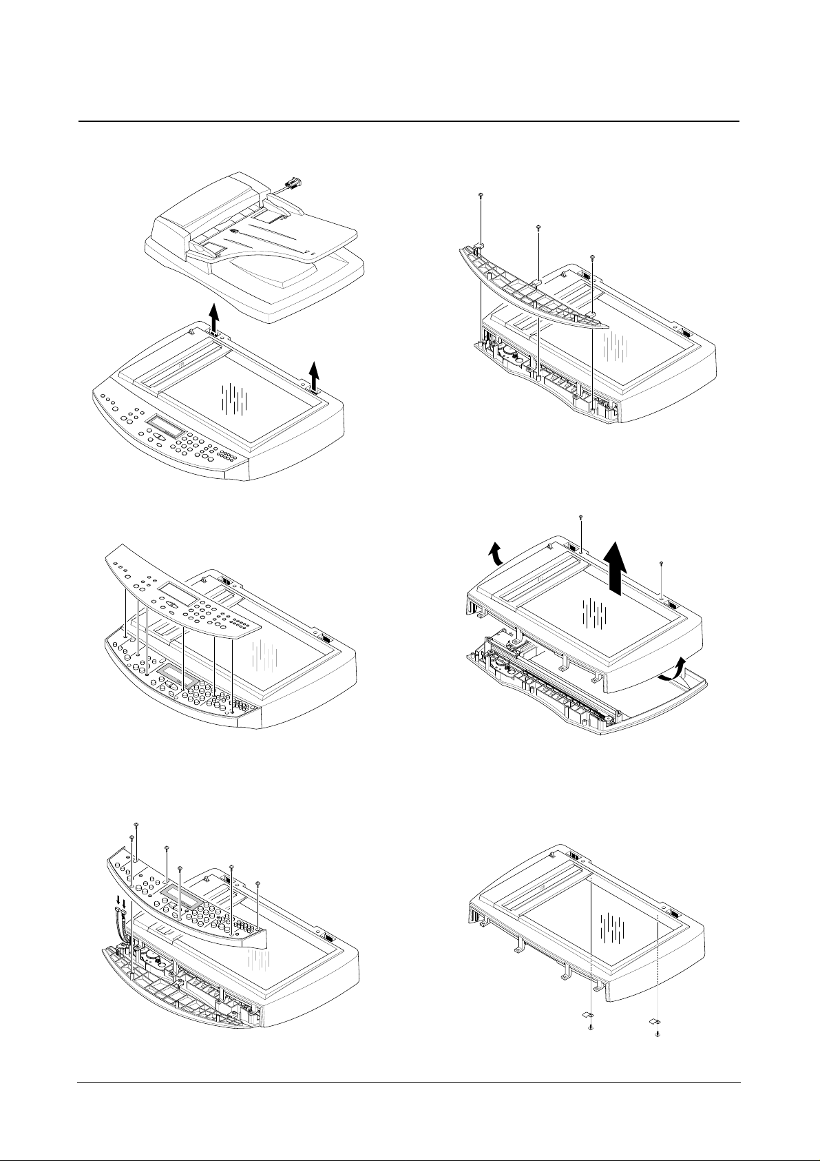
6. Pull the ADF unit (Platen Cover) upward and remove
it.
7. Pull the OPE Cover upward and remove it.
8. Remove six screws securing the OPE Upper and
unplug the two connectors from the OPE Panel.
9. Remove three screws securing the OPE Lower and
remove it.
10. Remove two screws and unlatch the Scan Lawer
securing the Scan Upper and remove it.
11. Remove the two screws securing the Scan Upper
and take out the Glass Holder.
Disassembly and Reassembly
3-4
Samsung Electronics
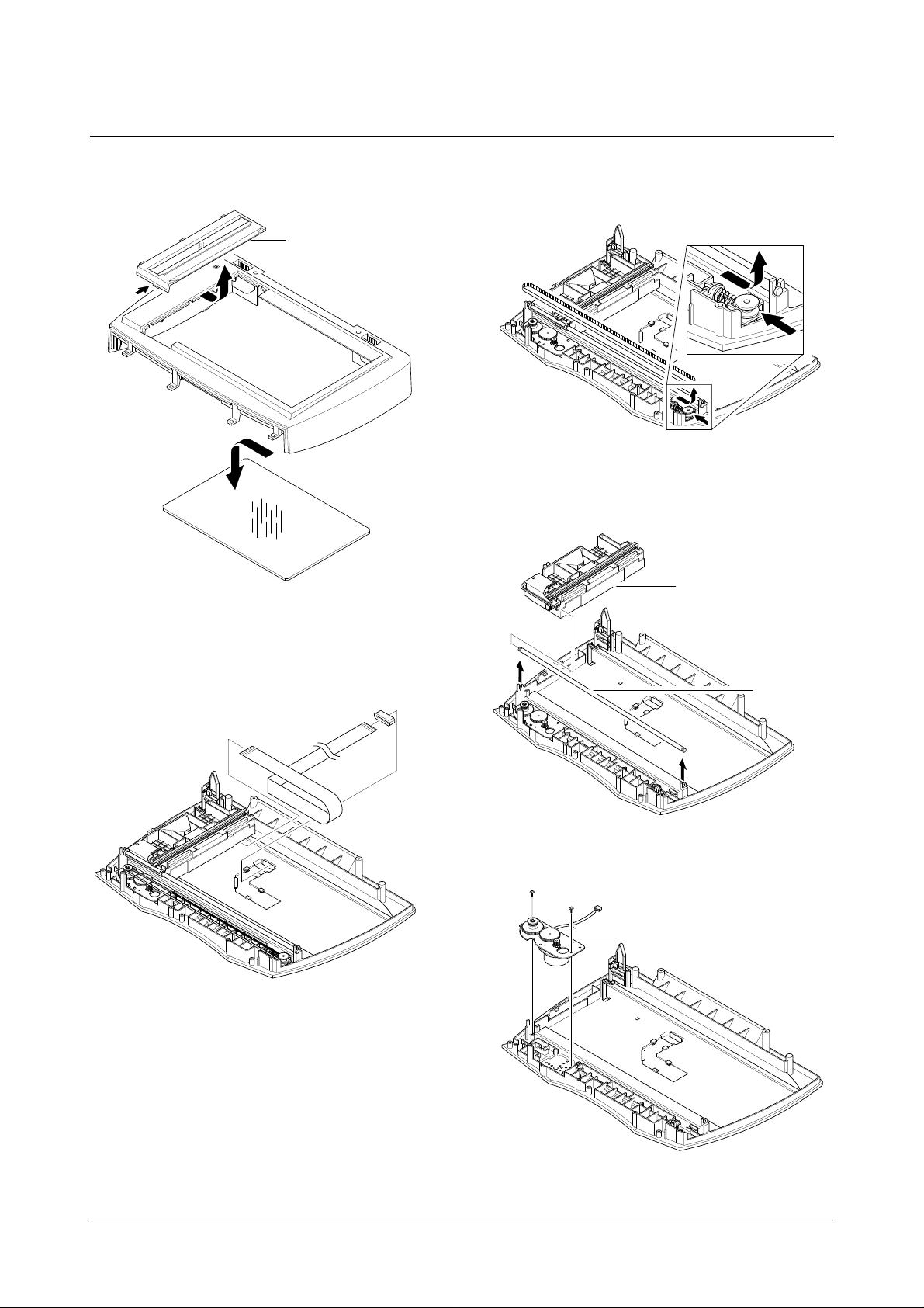
12. Unlatch the Scan Dummy and take out the Glass
from the Scan Upper.
13. Remove the CCD Cable.
14. Push the Belt Holder and take out the Belt, as shown
below.
15. Pull up the CCD Shaft and take out the Scanner
Module.
16. Remove two screws and take out the Motor Bracket.
Motor Bracket.
CCD Shaft
Scanner Module.
Scan Dummy
Disassembly and Reassembly
3-5
Samsung Electronics
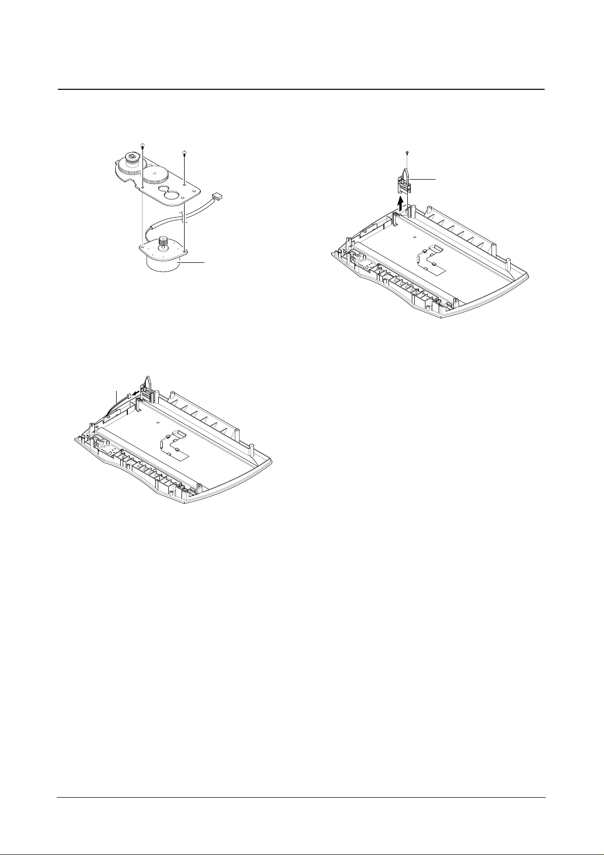
17. Remove two screws securing the Scan Motor and
remove it.
18. Unplug the one connector from the open Sensor
ASS’Y.
19. Remove the one screw securing the open Sensor
ASS’Y and remove it.
Sensor ASS Y
Scan Motor
OPE Harness
Disassembly and Reassembly
3-6
Samsung Electronics
3-3 ADF Motor ASS’Y
1. Before you remove the ADF Motor ASS’Y, you should
remove:
• Scanner ASS’Y (see page 3-2)
2. Remove the four screws securing the TX Stacker and
remove it.
3. Take out the ADF connector.
4. Remove the four screws securing the Side Cover(L,R)
and remove it.
5. Remove the two screws securing the ADF Unit and
remove it.
TX Stacker
Side Cover R
Side Cover L
ADF connector
 Loading...