

Samsung SCX 1100 Service Manual
SERVICE
SAMSUNG
INKJET PRINTER(MFP)
SCX-1100
Manual
INKJET PRINTER(MFP) CONTENTS
1. Precautions
2. Specifications
3. Disassembly and Reassembly
4. Troubleshooting
5. Exploded Views and Parts List
6. Block Diagram
7. Connection Diagram

ELECTRONICS
© Samsung Electronics Co.,Ltd. March
2001
Printed in Korea.
VERSION NO. : 1.02 CODE : JB-0023A
This service manual is also provided on the web,
the ITSELF system Samsung Electronics Co., Ltd.
“http://itself.sec.samsung.co.kr”
- This Service Manual is a property of Samsung Electronics Co.,Ltd.
Any unauthorized use of Manual can be punished under applicable
International and/or domestic law. -

This manual is stated and
provided for service description.
All rights reserved. Any parts of the
information in this manual are prohibited
from free duplication, use or translation
without prior written approval except in
cases allowed by the Copyright Act.
Specifications are subject to change without
prior notice.
Copyright (c) 2002. 3.
Samsung Electronics Digital Printing CS Group
1-1
Samsung Electronics
1. Precautions
Please read the following carefully to prevent any accidents and not to damage the unit during service.
1-1 Safety Precautions
1-2 Precautions on Disassembly and Reassembly
1. Safety Precautions
There are some electric or machinery parts with safety
related property. If the parts replaced are different from
the original, the safety may not function. Even if the part
could allow higher voltage than that of the part used, do
not replace it and use a regular product clarified in specifications.
2. Be careful not to leave a switch, a cover or a safety device
out when reinstalling or assembling the product after
repair.
3. Replacing Precautions
Do not change or add parts as you like. You cannot benefit from such a remodeled product at your will during the
term of guarantee.
4. You must replace overheated or damaged parts or cords
with regular products. Please solve the problem causing
any damage or overheating and troubles beforehand.
Especially mind the safety on the part with this
mark.
You must use regular parts described in specifications for the parts inflammable and where the current can be flown. Otherwise any hazard such as
an electric shock or a fire could occur .
Very careful precautions should be taken when replacing
parts. Before replacing, please check cables because you
cannot put the cables that you removed for replacing parts
into the proper place if you would not make sure of where
they were connected and in which condition.
Please do the following before disassembling
for a repair or replacement of parts.
1. Pull out paper cassette, printer cartridge installed.
Especially careful not to be scratched by the surface of
developer or not to expose them to light.
2. Turn the power switch off.
3. Take out the power plug, printer cable from the printer.
4. Use only the same type of part as original when replacing
parts.
5. Do not force to open or fasten plastic material components.
6. Be careful that small parts such as screws should not get
in the printer.
7. When disassembling, assembling, also observe small
components are located in place.
8. If you uncover and turn the machine over to replace some
parts, toner or paper particles may contaminate the LSU
window. Protect the LSU window with clean paper.
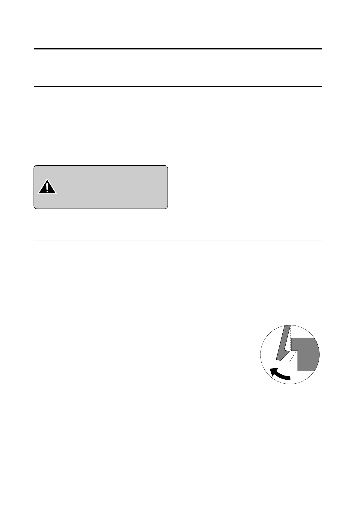
Releasing Plastic Latches
Many of parts are held in
place with plastic latches.
The latches break easily :
release them carefully.
To remove such parts, press
the hook end of the latch
away from the part to which
it is latched.

Certain semiconductor devices can be easily damaged by
static electricity. Such components are commonly called
“Electrostatically Sensitive (ES) Devices”, or ESDs.
Examples of typical ESDs are: integrated circuits, some field
effect transistors, and semiconductor “chip” components.
The techniques outlined below should be followed to help
reduce the incidence of component damage caused by static electricity.
1. Immediately before handling a semiconductor component or semiconductor-equipped assembly, drain off any
electrostatic charge on your body by touching a known
earth ground. Alternatively, employ a commercially available wrist strap device, which should be removed for your
personal safety reasons prior to applying power to the unit
under test.
2. After removing an electrical assembly equipped with
ESDs, place the assembly on a conductive surface, such
as aluminum or copper foil, or conductive foam, to prevent electrostatic charge buildup in the vicinity of the
assembly .
3. Use only a grounded tip soldering iron to solder or desolder ESDs.
4. Use only an “anti-static” solder removal device. Some solder removal devices not classified as “anti-static” can
generate electrical charges sufficient to damage ESDs.
5. Do not use Freon-propelled chemicals. When sprayed,
these can generate electrical charges sufficient to damage ESDs.
6. Do not remove a replacement ESD from its protective
packaging until immediately before installing it. Most
replacement ESDs are packaged with all leads shorted
together by conductive foam, aluminum foil, or a comparable conductive material.
7. Immediately before removing the protective shorting
material from the leads of a replacement ESD, touch the
protective material to the chassis or circuit assembly into
which the device will be installed.
8. Maintain continuous electrical contact between the ESD
and the assembly into which it will be installed, until completely plugged or soldered into the circuit.
9. Minimize bodily motions when handling unpackaged
replacement ESDs. Normal motions, such as the brushing together of clothing fabric and lifting one’s foot from a
carpeted floor, can generate static electricity sufficient to
damage an ESD.
1-3 ESD Precautions
Precautions
1-2
Samsung Electronics
CAUTION:
Be sure no power is applied to the chassis or circuit, and observe all other safety precautions.
Precautions
1-3
Samsung Electronics
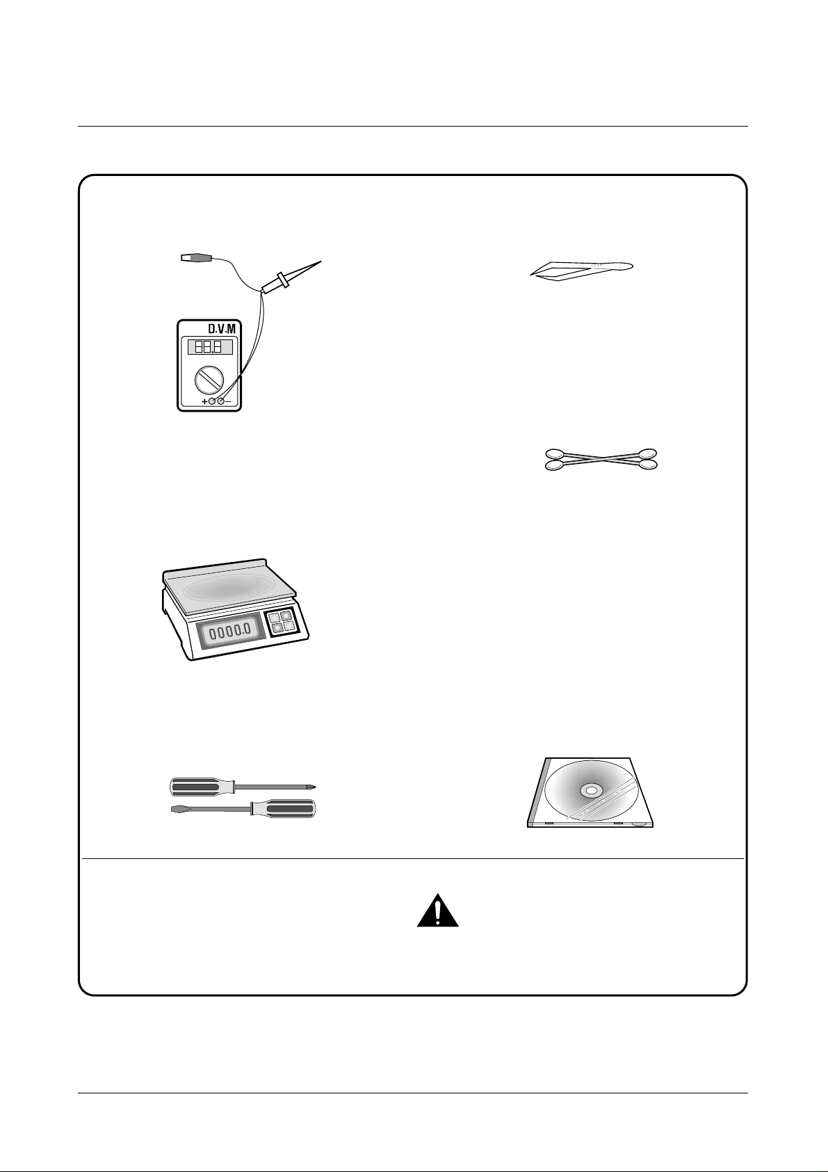
1-4 Tools for Troubleshooting
The following tools are recommended for safe and smooth troubleshooting described in this service manual.
DVM(Digital Volt Meter)
Standard: Indicates more than 3 digits.
Electronic Scale
Standard: Equipment to check the weight of consumables supplied by Samsung Electronics.
(The gram unit can be measured.)
Driver
Standard: "-" type, "+" type (M3 long, M3 short,
M2 long, M2 short).
Pinset
Standard: For general home use, small type.
Cotton Swab
Standard : For general home use, for medical ser-
vice.
Cleaning Equipments a IPA(Isopropyl
Alcohol)dry cloth or a soft stuff neutral
detergent.
Software(Driver) installation CD ROM
Mind your hands not to be touched when you
disassemble and reassemble PBAASS'Y, such as
the main board.
Note
1
2
3
4
5
6
7
Samsung Electronics
2-1
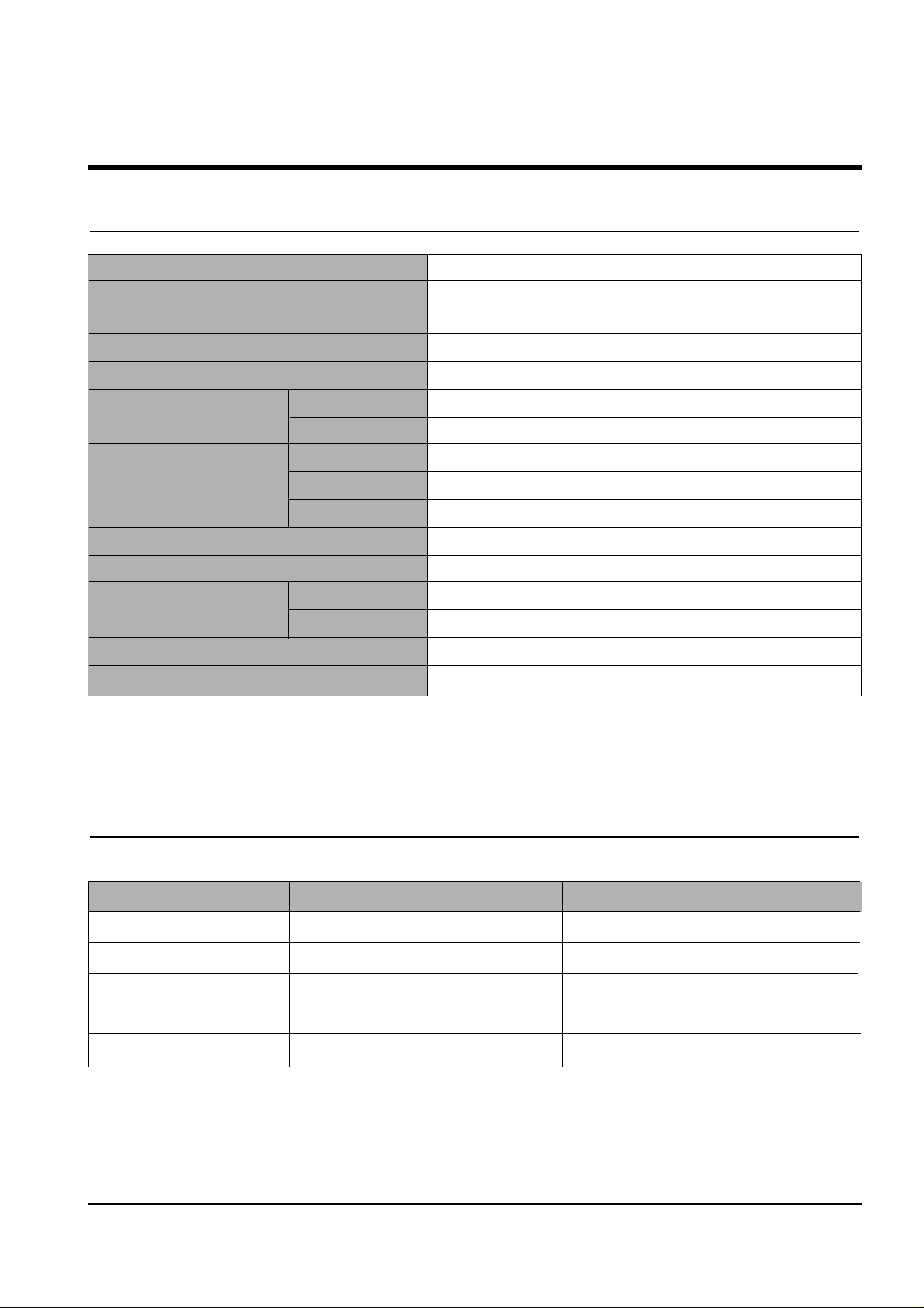
2. Specifications
2-1 Printer Engine
2-2 Ink Cartridge
Babbage mono standard Birch color
Model No. M50 C60
Print Head 208 nozzles 192 nozzles
Ink type Pigment Dye
Ink Color Black (Babbage) Color (Birch)
Ink Yield about 1075 sheets (5% Pattern, A4) about 275 sheets (15% Pattern, A4)
Technology Color Thermal Inkjet
Engine Type 2-Pen (K and CMY)
Operating System Windows 95/98/2000/Me/XP
Interface USB (without HUB Mode), Centronics 1284
Emulation HBP(GDI)
Print Speed
(2)
Mono 14 ppm Draft / 10 ppm Normal
Color 7 ppm Draft / 2 ppm Normal
Print Resolution (H x V) Quick 300 x 600 dpi
Normal 600 x 600 dpi
High Quality 2400(H) x 1200(V) dpi (Addressable)
Maximum Paper Size A4, Letter, Legal, Banner
Effective Printing Width 8.0'' (203 ± 1mm)
Feeding Method Automatic 100 Sheets (Maximum stacking height : 9mm)
Manual Tray No
Output Tray Capacity Maximum 30 sheets
Maximum Cable Length USB Cable, Max 6ft
(3)
Note:
(2) Speed claims based on the test files: spdtstc.sam(mono), spdtstc2.sam(color)/Letter size
(3) Non-standard cable can cause misoperations.

Samsung Electronics
Specifications
2-2
2-3 Copier
Scanner Type Flat-bed without ADF (Automatic Document Feeder)
Maximum Original Size A4/Letter
Maximum Paper Size A4/Letter/Legal
Maximum Scan Width 216 mm
Optical Resolution (HxV) 600 x 600 dpi
Copy Quality Draft, Normal, Best
Paper Type Selection Plain, Glossy, Transparency
Mono Copy Speed
(1)
Draft: 10cpm
Color Copy Speed
(1)
Draft: 5cpm
Effective Print-edge Margin Top: 3.4mm, Bottom: 19.05mm, Each Side: 6.5mm(LTR), 3.5mm(A4)
Multi copy 99 pages (Memory Multi copy)
Zoom Rate 25 % ~ 400 % (1 % Step)
Contrast Control 3 Steps
Ink Saver Mode Use Draft Mode (<20 % Savings)
Auto Sensing Check Paper Jam , Low Ink
Note:
(1) Speed claims based on the test chart : Printed spdtstc.sam(mono), Printed spdtstc2.sam(color)/Letter size
2-4 Scanner
Operation System Windows 98/Me/2000/XP
Interface USB (without HUB Mode) and Centronics 1284
Compatibility TWAIN Standard.
Device Platen Color CCD
Scan Width Max.: 8.5” (216 mm), Effective: 8.2” (210 mm)
Color Depth Internal 36 bit, External 24 bit
Optical Resolution (H x V) 600 x 1200 dpi
Interpolation Resolution Max. 4800 dpi
Pre-scan Mode Yes, 75 dpi
Scan Speed about 2'30 sec/A4 True Color
(Pentium II 300M, 64MB Memory, 300dpi)
Samsung Electronics
Specifications
2-3
2-5 Power Supply
Rated AC Input Voltage 110 ~ 240 VAC (Universal)
Rated Input Frequency 50 ~ 60 Hz
Minimum/Maximum AC Input 90 VAC/265 VAC
Maximum Input Current 0.5 A
DC Channels
(4)
(2 Channels) +3.3V +
5%, +30V +10%
External Power On/Off Key Power Down Key (It does not cut the primary power input off)
2-6 Dimension
Machine Size (W x D x H, mm) 477(W) X 415(D) X 252(H)
Machine Weight About 8.5 Kg (Machine itself)
Note:
(4) No load condition.
2-7 Environmental Condition
Absolute Storage Temperature
(5)
-20oC ~ 55oC
Absolute Storage Humidity
(5)
10% RH ~ 90% RH
Recommended Temperature 5oC ~ 40oC
Operating Condition Humidity 15% RH ~ 85% RH
Note:
(5) Packing Condition
3. Disassembly and Reassembly
3-1 General Precautions on Disassembly
When you disassemble and reassemble components, you
must use extreme caution.
The close proximity of cables to moving parts makes proper
routing a must. If components are removed or replaced, any
cables disturbed by the procedure must be replaced as close
as possible to their original positions.
Before removing any component from the machine, note the
cable routing that will be affected.
Whenever servicing the machine, you must perform as follows:
1. Check to verify that documents are not stored in memory.
2. Unplug the power cord.
3. Use a flat and clean surface.
4. Replace only with authorized components.
5. Do not force to remove or planten plastic-material components.
6. Make sure all components are in their proper position.
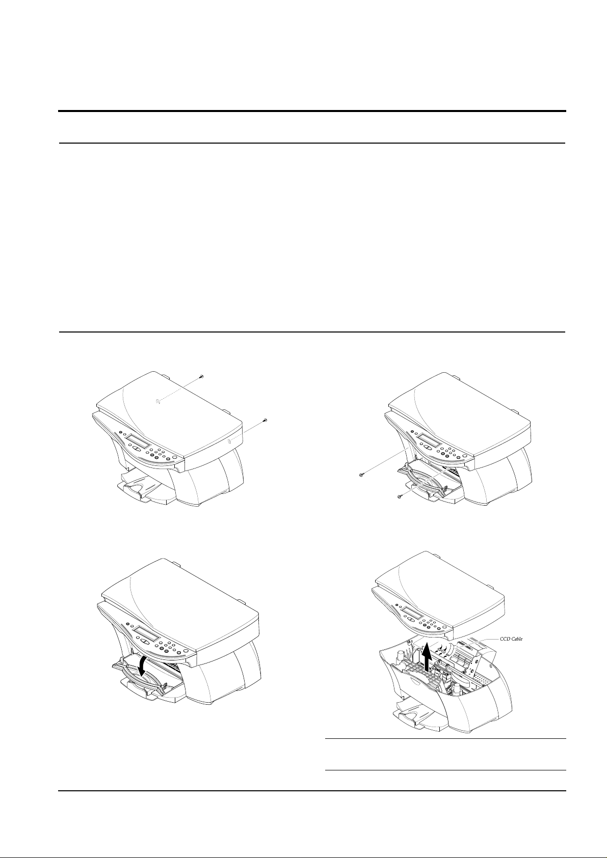
3-2 Scanner Ass'y
1. Remove two screws securing the rear cover.
2. Open the front door from the main cover.
3. Remove two screws securing the main cover.
4. Pull the scanner ass'y upward then, unplug the two
connectors and CCD cable.
Note :
You should connect or remove the CCD cable vertically to avoid the CCD cable pin damage.
3-1samsung Electronics
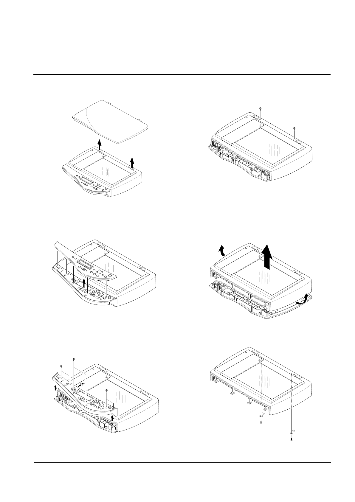
5. Pull the platen cover upward and remove it.
6. Pull the OPE cover upward and remove it.
7. Remove five screws securing the OPE upper and
unplug the one connector from the OPE panel.
8. Remove two screws securing the scan upper and
remove it.
9. Unlatch the scan lawer securing the scan upper and
remove it.
10. Remove the two screws securing the scan upper.
3-2 samsung Electronics
Disassembly and Reassembly
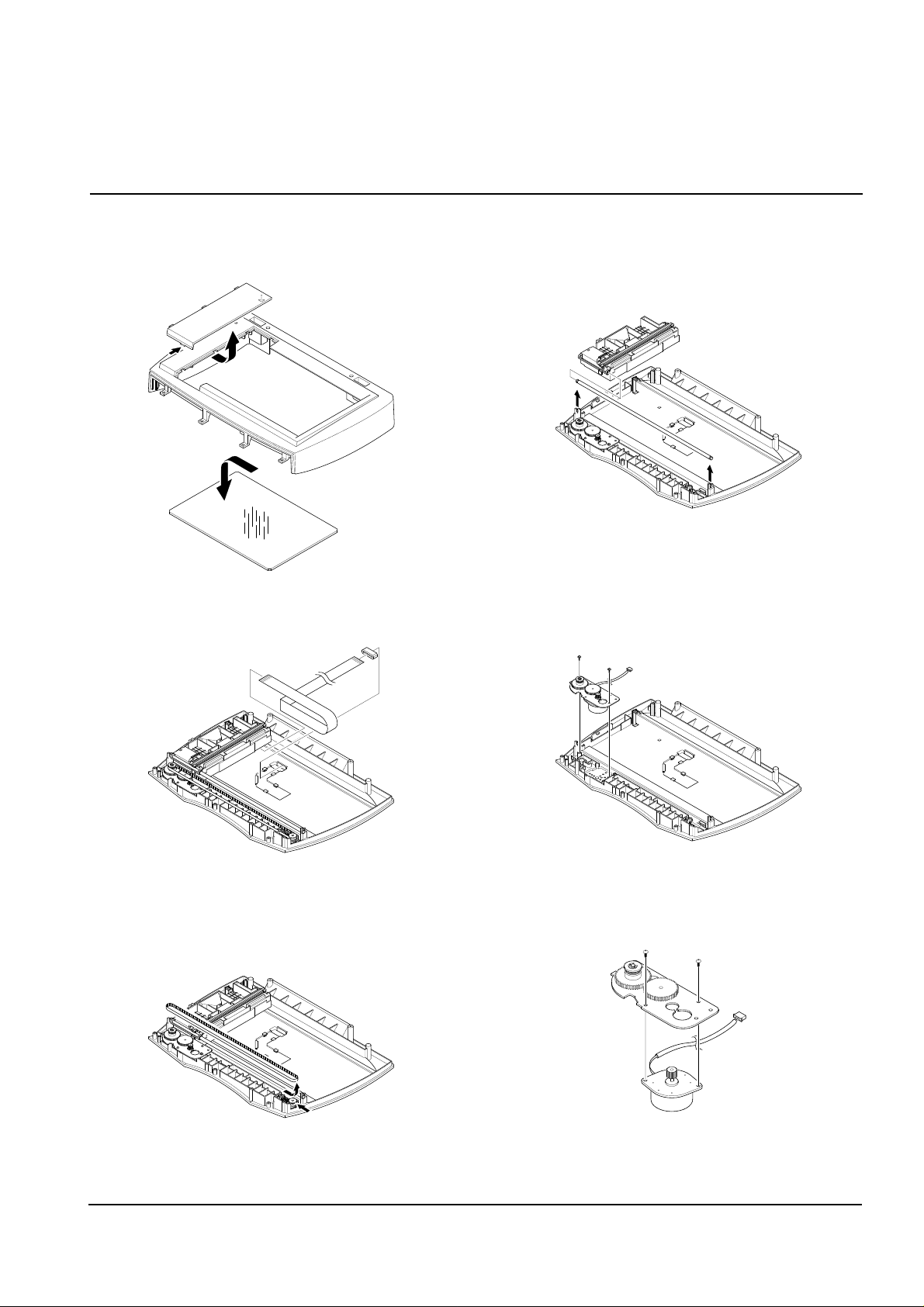
11. Unlatch the scan dummy and take out the glass
from the scan upper.
12. Remove the CCD cabl.
13. Push the belt holder and take out the belt, as
shown below.
14. Pull up the CCD shaft and take out the scanner
module.
1
5. Remove two screws and take out the motor bracket.
16. Remove two screws securing the scan motor and
remove it.
samsung Electronics 3-3
Disassembly and Reassembly
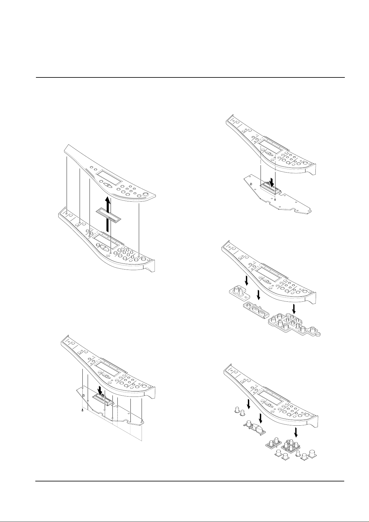
3-3 OPE Unit
1. Before you remove the ope unit, you should remove:
• Scanner Ass'y (see page 3-1)
2. Pull the OPE cover upward and remove it.
Take out the LCD window from the OPE cover.
3. Remove five screws securing the OPE upper to the
OPE PBA.
4. Remove two screws securing the OPE upper to the
LCD board.
5. Remove the contact rubber from the OPE upper.
6. Remove the Key pad from the OPE upper.
3-4 samsung Electronics
Disassembly and Reassembly
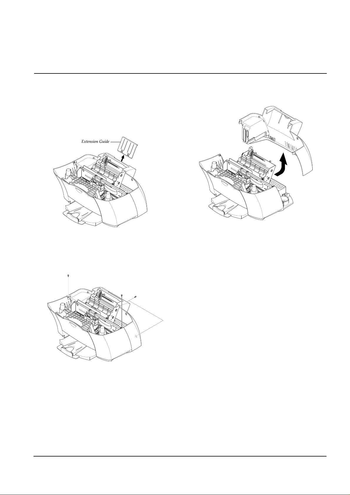
3-4 Rear Cover
1. Before you remove the rear cover, you should
remove:
• Scanner Ass'y (see page 3-1)
2. Pull the extension guide upward and remove it.
3. Remove four screws securing the rear cover.
4. Remove the rear cover, as shown below.
samsung Electronics 3-5
Disassembly and Reassembly
samsung Electronics
Disassembly and Reassembly
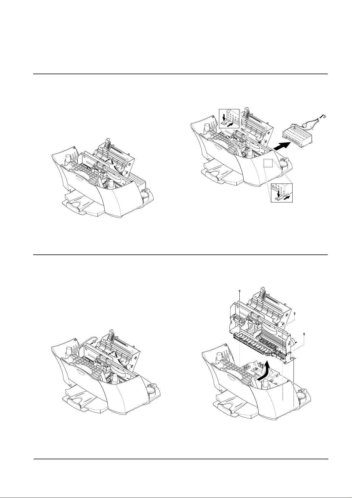
3-5 SMPS
1. Before you remove the SMPS, you should remove:
• Scanner Ass'y (see page 3-1)
• Rear Cover (see page 3-5)
2. Unplug the one connector from the main PBA.
3. Pushing down the hooks on both ends, pullout the
SMPS.
3-6
3-6 Engine Ass'y
1. Before you remove the engine ass'y you should
remove:
• Scanner Ass'y (see page 3-1)
• Rear Cover (see page 3-5)
2. Unplug the SMPS connector and cover open sensor
connector from the main PBA.
3. Remove the three screws securing the engine ass'y
and remove it.
samsung Electronics
Disassembly and Reassembly
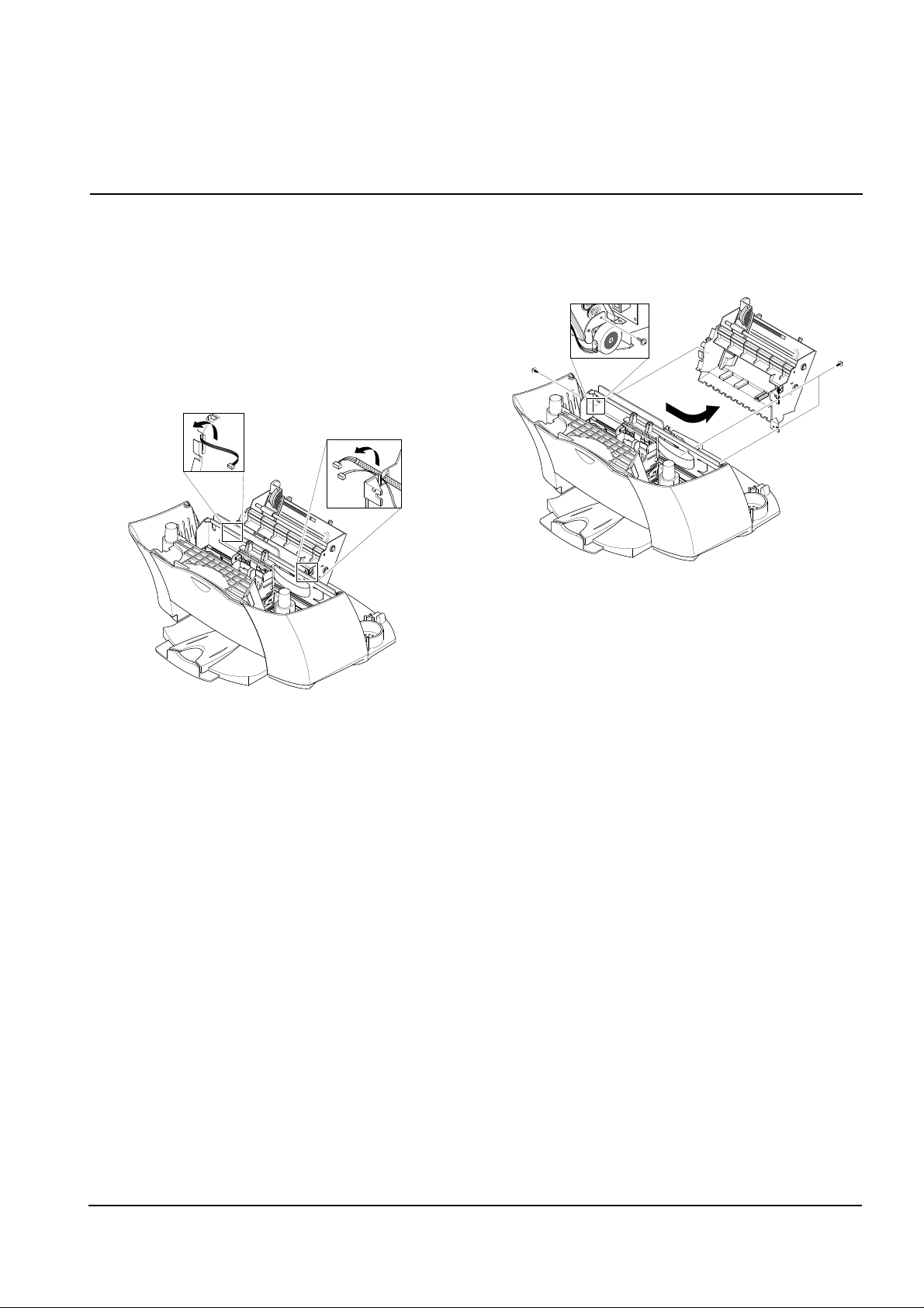
3-7 ASF Feeder
1. Before you remove the asf feeder, you should
remove:
• Scanner Ass'y (see page 3-1)
• Rear Cover (see page 3-5)
• SMPS (see page 3-6)
2. Make sure the harness is released from the hooks,
as shown below.
3. Remove three screws securing the ASF feeder to the
main cover.
Take out the ASF feeder.
3-7
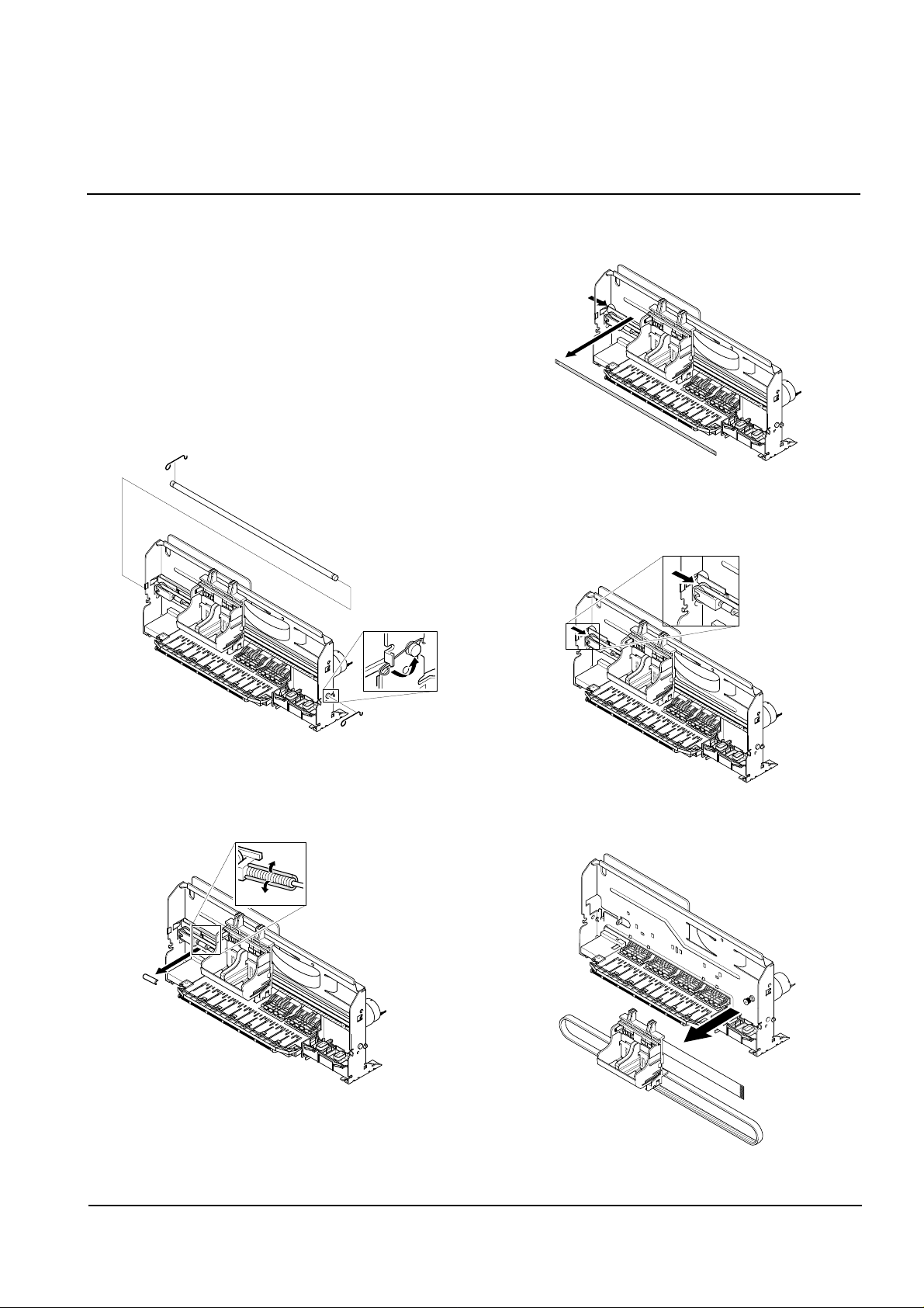
3-8 Cartridge Ass'y
1. Before you remove the cartridge ass'y you should
remove:
• Scanner Ass'y (see page 3-1)
• Rear Cover (see page 3-5)
• Engine Ass'y (see page 3-6)
• ASF Feeder (see page 3-7)
2. Rotate to remove both springs securing the carrier
shaft. Then take out the carrier shaft.
3. Remove the C-cab.
4. Take out the emcoder strip, as shown below.
5. Push the holder pulley to the right and take out the
belt.
6. Take out the cartridge carrier from the main frame.
3-8 samsung Electronics
Disassembly and Reassembly
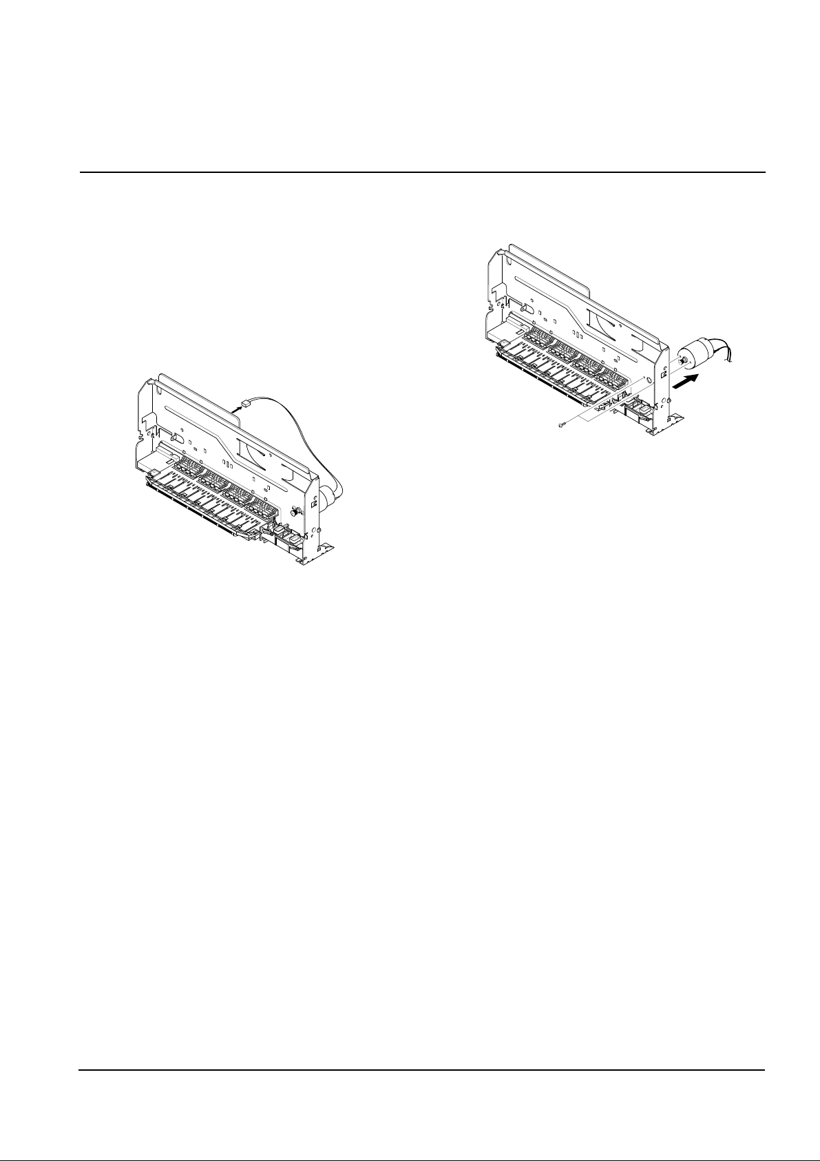
3-9 Carrier Motor
1. Before you remove the carrier motor, you should
remove:
• Scanner Ass'y (see page 3-1)
• Rear Cover (see page 3-5)
• Engine Ass'y (see page 3-6)
• ASF Feeder (see page 3-7)
• Cartridge Ass'y (see page 3-8)
2. Unplug the one connector from the main PBA.
3. Remove two screws securing the carrier motor and
take out the motor from the main frame.
samsung Electronics 3-9
Disassembly and Reassembly
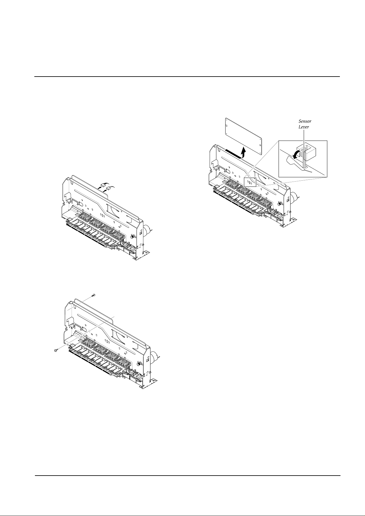
3-10 Main PBA
1. Before you remove the main PBA, you should
remove:
• Scanner Ass'y (see page 3-1)
• Rear Cover (see page 3-5)
• Engine Ass'y (see page 3-6)
• ASF Feeder (see page 3-7)
• Cartridge Ass'y (see page 3-8)
2. Unplug all connectors from the main PBA.
3. Remove the two screws securing the main PBA.
4. Pull the sensor lever backward and take out the main
PBA, as shown below.
3-10 samsung Electronics
Disassembly and Reassembly
samsung Electronics
Disassembly and Reassembly
3-11
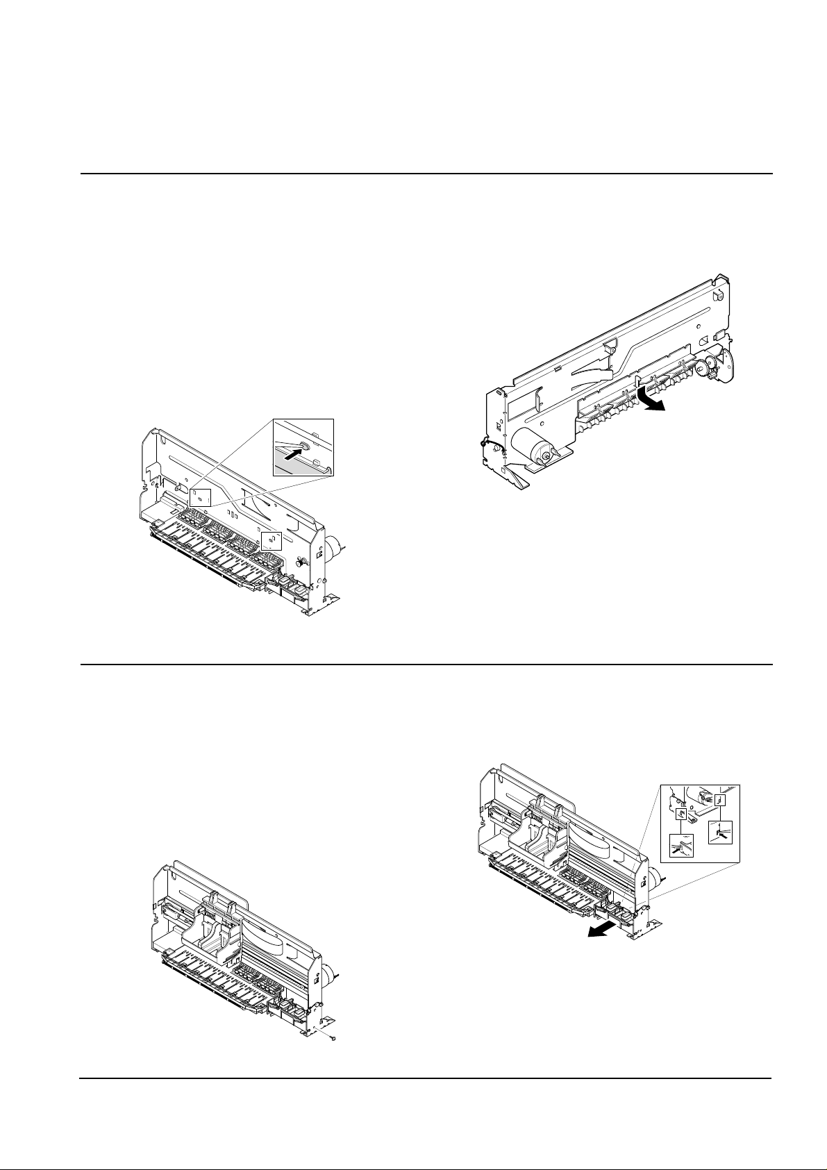
3-11 Holder Roller
1. Before you remove the holder roller, you should
remove:
• Scanner Ass'y (see page 3-1)
• Rear Cover (see page 3-5)
• Engine Ass'y (see page 3-6)
• ASF Feeder (see page 3-7)
• Cartridge Ass'y (see page 3-8)
• Main PBA (see page 3-10)
2. Unlatch the holder by pushing the parts hooked to
the main frame using a sharp tool.
3. Pull the holder downward and take it out from the
main frame.
3-12 Home Ass'y
1. Before you remove the home ass'y you should
remove:
• Scanner Ass'y (see page 3-1)
• Rear Cover (see page 3-5)
• Engine Ass'y (see page 3-6)
• ASF Feeder (see page 3-7)
2. Remove one screw securing the home ass'y.
3. Unlatch the home ass'y by pushing the parts hooked
to the main frame using a sharp tool. Take out the
home ass'y from the main frame.
samsung Electronics
Disassembly and Reassembly
3-12
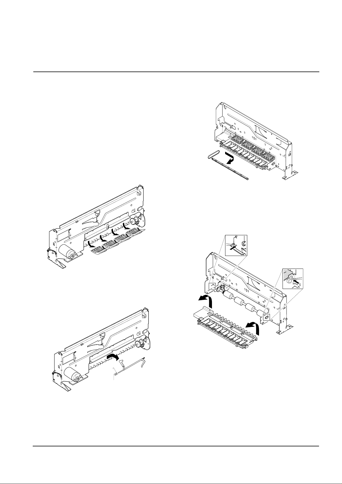
3-13 Base Frame
1. Before you remove the base frame, you should
remove:
• Scanner Ass'y (see page 3-1)
• Rear Cover (see page 3-5)
• Engine Ass'y (see page 3-6)
• ASF Feeder (see page 3-7)
• Cartridge Ass'y (see page 3-8)
• Main PBA (see page 3-10)
• Hold Roller (see page 3-11)
• Home Ass'y (see page 3-11)
2. Remove the four springs and take out the four roller
frictions, as shown below.
3. Take out the actuator feed from the main frame, as
shown below.
4. Remove the exit roller from the main frame and take
out the exit belt.
5. Unlatch the base frame ass'y by pushing the parts
hooked to the main frame using a sharp tool, as
shown below.
samsung Electronics
Disassembly and Reassembly
3-13
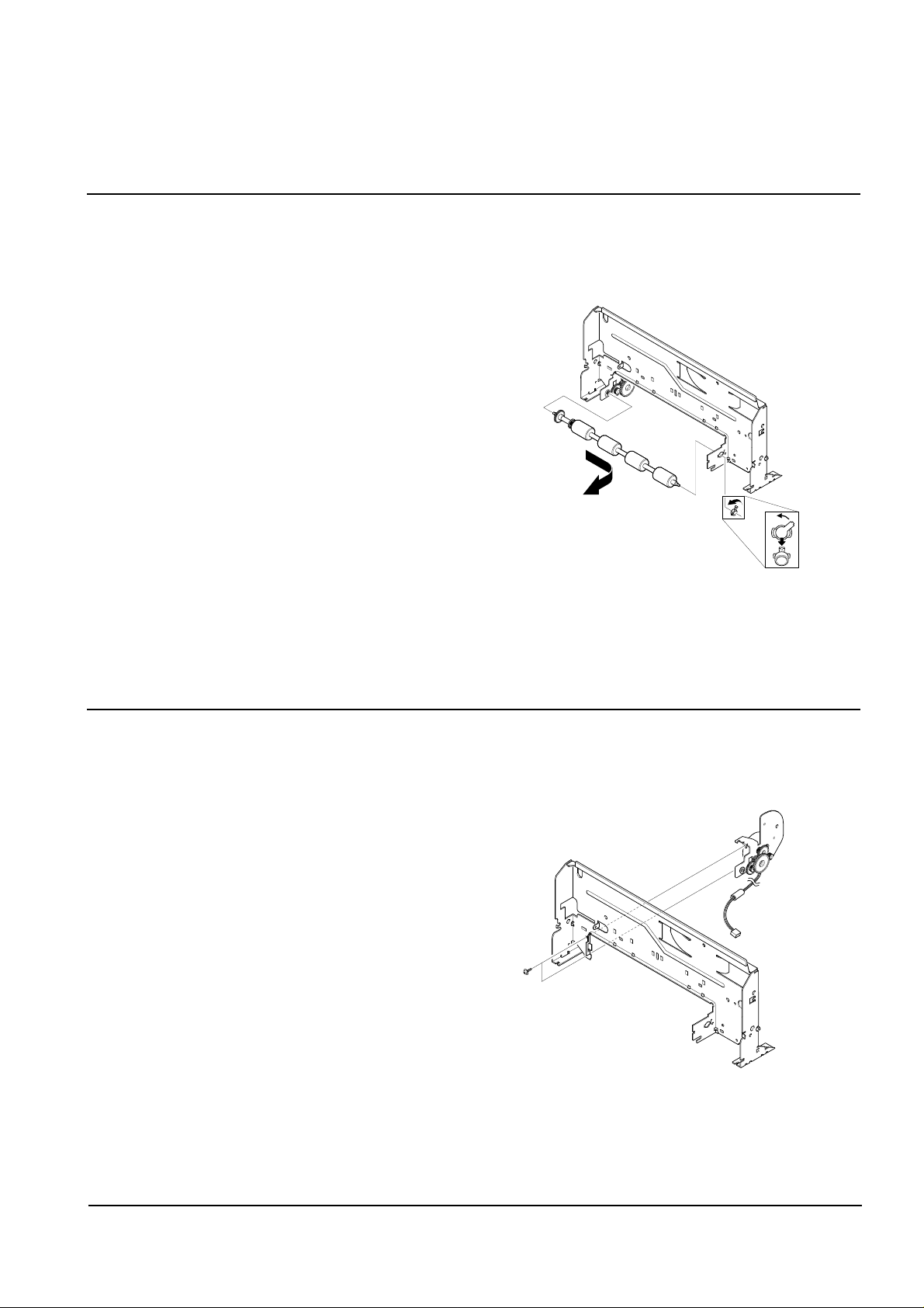
3-14 Feed Roller
1. Before you remove the feed roller, you should
remove:
• Scanner Ass'y (see page 3-1)
• Rear Cover (see page 3-5)
• Engine Ass'y (see page 3-6)
• ASF Feeder (see page 3-7)
• Cartridge Ass'y (see page 3-8)
• Main PBA (see page 3-10)
• Hold Roller (see page 3-11)
• Home Ass'y (see page 3-11)
• Base Frame (see page 3-12)
2. Turn the bearing feed counterclockwise and take out
the base frame and feed roller from the main frame.
3-15 Line Feed Bracket Ass'y
1. Before you remove the LF bracket ass'y, you should
remove:
• Scanner Ass'y (see page 3-1)
• Rear Cover (see page 3-5)
• Engine Ass'y (see page 3-6)
• ASF Feeder (see page 3-7)
• Cartridge Ass'y (see page 3-8)
• Main PBA (see page 3-10)
• Hold Roller (see page 3-11)
• Home Ass'y (see page 3-11)
• Base Frame (see page 3-12)
• Feed Roller (see page 3-13)
2. Remove two screws and take out the LF bracket
ass'y from the main frame.
4-1
Samsung Electronics
4. Troubleshooting
4-1 Setting-up System in User Mode
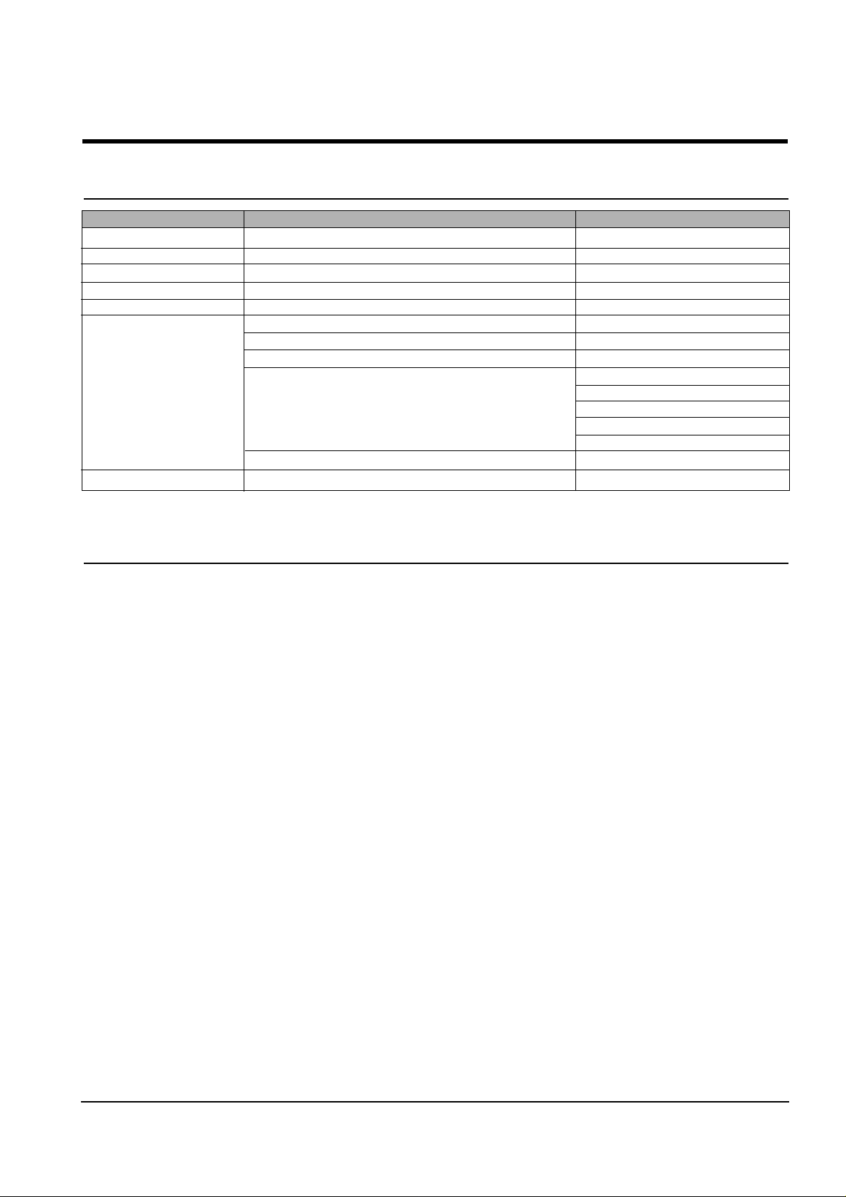
FUNCTION ITEM DEFAULT
LANGUAGE ENG/GER/FRE/ITA/SPA/POR/DUT ENGLISH
POWER SAVE MODE 1/4/8/12 HOUR 1
PAPER SIZE LETTER/A4/LEGAL A4
P APER TYPE PLAIN/INKJET/PHOTO/TRANSPARENCY PLAIN PAPER
MAINTENANCE CLEAN CARTRIDGE
ALIGN CARTRIDGE
VIEW INK LEVEL "COLOR : _/8 , BLOCK : _/8"
HELP LIST
DEFAULT SETUP CONTRAST
QUALITY
COPY P AGE
ZONE RATE
RESOLUTION
ADJUST SHADING
KEY SOUND ON/OFF ON
4-2 Setting-up System in Service Mode
• How to enter service mode
In service (tech) mode, the technician can check the machine and perform various tests to isolate the cause of a malfunction.
To enter the service mode, press ENTER, LEFT, RIGHT, LEFT, SETUP in sequence, and the LCD displays ‘ T ’, the machine
has entered service (Tech) mode.
To return to normal user mode, press ENTER, LEFT, RIGHT, LEFT, SETUP in sequence again, or turn the power off, then
on by unplugging and plugging the power cord.
Because the explanation of the User Mode items is already mentioned at the User guide in detail, It will not be described at
Service manual.
4-2
Troubleshooting
Samsung Electronics
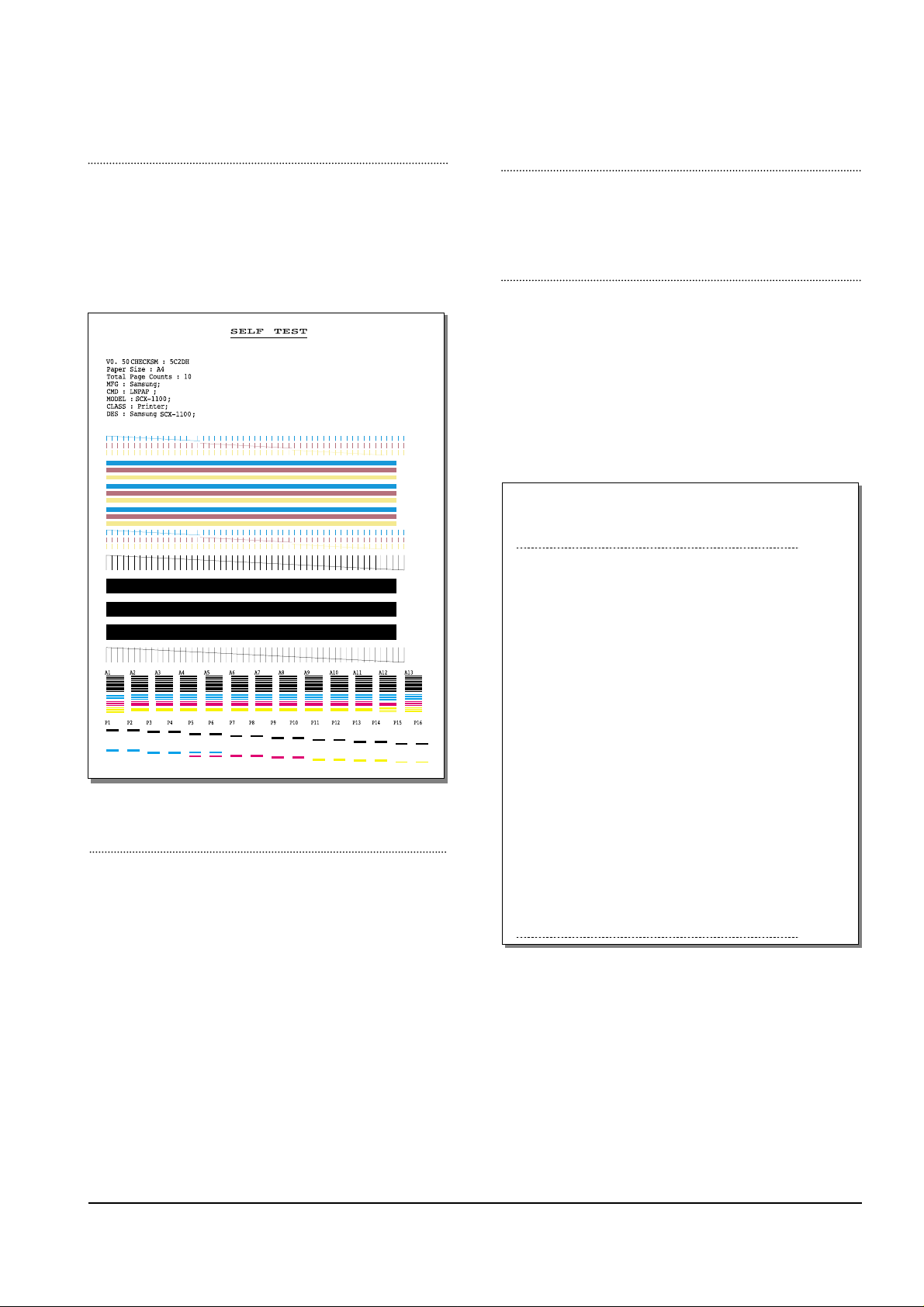
FACT OR Y SELFTEST
Using this pattern printout, you can check if the printer
mechanism is functioning properly. Examine the pattern
and look for a break in the diagonal line. If the diagonal
lines are not broken, the printer mechanism is functioning
properly .
ROM TEST
Use this feature to test the machine'S ROM. The result and the
software version appear in the LCD display .
PRINT NVRAM TEST
1. Press the SETUP button until “PRINT NVRAM DUMP”
is displayed in LCD.
2. Press the START button when the NVRAM Test opera-
tion menu displayed. And then the machine prints the
list for NVRAM testing.
The Remote Test feature can be enabled in order to allow
a remote location to call up and run a diagnostic test on
your machine. You may be instructed by a service representative to enable this feature.
NVRAM DUMP LIST
LIST Left Head Detect : 1c
Right Head Detect : 7
Left Head Type : 1c
Right Head Type : 7
< Device Identification >
MFG:Samsung;
CMD:LNPAP;
MODEL:SCX-1100;
CLASS :Printer;
DES:Samsung SCX-1100;
< Dot Count Variables >
Black Dot Count : 2436256
Color Cyan Dot Count : 1368128
Color Magenta Dot Count : 1368128
Color Yellow Dot Count : 1368128
Photo Black Dot Count : 0
Photo Cyan Dot Count : 0
Photo Magenta DotCount : 0
Total Black Dot Count : 2436256
Total Color Cyan Dot Count : 1368128
Total Color Magenta Dot Count : 1368128
Total Color Yellow Dot Count : 1368128
Total Photo Cyan Dot Count : 0
Total Photo Magenta Dot Count : 0
Total Photo Black Dot Count : 0
< Page Count Variables >
Total Page Count : 2
< Cartridge Types >
Left Cartridge Type : Color Standard Capacity
Right Cartridge Type : Black High Capacity
< Alignment Variables >
Horizontal Align Value : 15
Vertical Align Value : 8
Quick Black Bidi Align Value : 15
Quick Color Bidi Align Value : 15
Normal Black Bidi Align Value : 15
Normal Color Bidi Align Value : 15
Photo Horizontal Align Value : 15
Photo Vertical Align Value : 8
Photo Normal Black Bidi Align Value : 15
Photo Normal Color Bidi Align Value : 15
PROGRAM DOWNLOAD
Use this feature to download a new upgraded ROM file from
a PC which is connected to the machine with a parallel cable
(IEEE 1284).
< Download >
1. Connect printer to PC with a parallel cable(IEEE 1284.)
2. Select the PROGRAM DOWNLOAD function at the TECH
MODE.
3. Input COPY/B FILENAME PRN at the MS-DOS and push
the ENTER key .
(filename : the latest ROM file name when the downloading)
4. After the download is completed, the system will be automatically initialized.
4-3
Troubleshooting
Samsung Electronics
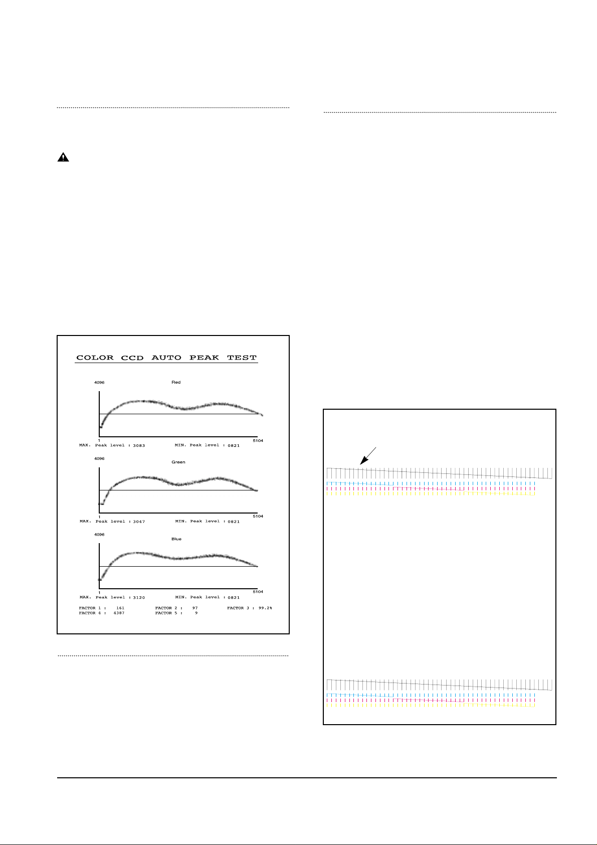
PRINT CCD PATTERN
It is used to adjust the light of CCD. It is already set at
CCD Test to get optimum quality.
NOTICE
When you test CCD, make sure that the cover is
closed.
1. Press the SETUP button until “Print CCD Pattern” is
displayed in LCD.
2. Press the START button when the CCD Test operation
menu displayed.
3. After scanner calibrating, wave form will be automatically printed out.
All the wave forms should be similar each other. CCD
problems may occur, if:
• More than one of the wave forms are straight lines.
• All wave forms are positioned under the center line.
WHITE LINES ON LETTERS OR GRAPHICS
• Cause
If nozzles in print head has a problem, white lines are
marked on the print.
‘CARTRIDGE MAINTENANCE’ will let you know if nozzles have fallen problems.
• Solution
1
) Run ‘print control panel’ to “clean print nozzles” and check if
nozzles have been blocked.
2) Wipe
with soft cloth the contact surfaces of ink cartridge and car-
riage, and check if nozzles have been cleaned properly.
3) Separate ink cartridge from carriage and combine them.
Repeat it about 5 to 6 times and check if connection is proper.
4) Replace ink cartridge and check whether there’s a problem
with the head.
5) Check if head cable is inserted well into the main circuit board
and then check if nozzles have problems.
6) Check if head cable is broken or torn and then check if nozzles
have problems.
7) Replace the main circuit board with a new one and
check if nozzles have problems.
MEMORYALL CLEAR
Initiating this function will put the system into the factory
shipping state. The procedure is as follows :
1. Unplug power
2. Press and hold " SETUP" button
3. Plug power in
4. Continue holding " SETUP" button until CLEARING
MEMORY message appears on LCD
5. Unplug power
If this line is broken, it confirms that nozzles
have problems.

4-4
Troubleshooting
Samsung Electronics
4-3. Troubleshooting
4-3-1 Defective PC Scan . . . . . . . . . . . . . . . . . . . . . . . . . . . . . . . . . . . . . . . . . . . . . . . .page(4-5)
4-3-2 Defective Image quality of PC Scan . . . . . . . . . . . . . . . . . . . . . . . . . . . . . . . . . . .page(4-5)
4-3-3 Defective Operation (LCD WINDOW ) Display . . . . . . . . . . . . . . . . . . . . . . .page(4-6)
4-3-4 No Power . . . . . . . . . . . . . . . . . . . . . . . . . . . . . . . . . . . . . . . . . . . . . . . . . . . . . .page(4-6)
4-3-5 Defective LCD Operation . . . . . . . . . . . . . . . . . . . . . . . . . . . . . . . . . . . . . . . . . . .page(4-7)
4-3-6 Defective Operation of Key Button . . . . . . . . . . . . . . . . . . . . . . . . . . . . . . . . . . . .page(4-7)
4-3-7 Paper Jam . . . . . . . . . . . . . . . . . . . . . . . . . . . . . . . . . . . . . . . . . . . . . . . . . . . . . .page(4-8)
4-3-8 Defective Paper Feed (1) . . . . . . . . . . . . . . . . . . . . . . . . . . . . . . . . . . . . . . . . . . .page(4-8)
4-3-9 Defective Paper Feed (2) -Display of NO PAPER . . . . . . . . . . . . . . . . . . . . . . . . .page(4-9)
4-3-10 Multi-Feeding . . . . . . . . . . . . . . . . . . . . . . . . . . . . . . . . . . . . . . . . . . . . . . . . . . . .page(4-9)
4-3-11 Defective Sensing-ink . . . . . . . . . . . . . . . . . . . . . . . . . . . . . . . . . . . . . . . . . . . .page(4-10)
4-3-12 Defective Sensing-paper . . . . . . . . . . . . . . . . . . . . . . . . . . . . . . . . . . . . . . . . . .page(4-10)
4-3-13 Defective Motor Drive (LF) . . . . . . . . . . . . . . . . . . . . . . . . . . . . . . . . . . . . . . . . .page(4-11)
4-3-14 Defective Motor Drive (CR) . . . . . . . . . . . . . . . . . . . . . . . . . . . . . . . . . . . . . . . .page(4-11)
4-3-15 Defective Motor Drive (Scan) . . . . . . . . . . . . . . . . . . . . . . . . . . . . . . . . . . . . . . .page(4-12)
4-3-16 Blank Page Print Out (When Copying) . . . . . . . . . . . . . . . . . . . . . . . . . . . . . . . .page(4-12)
4-3-17 Vertical Black Line (When Copying) . . . . . . . . . . . . . . . . . . . . . . . . . . . . . . . . . .page(4-13)
4-3-18 Contaminated Stains on Paper . . . . . . . . . . . . . . . . . . . . . . . . . . . . . . . . . . . . . .page(4-13)
4-3-19 Bad printed Image . . . . . . . . . . . . . . . . . . . . . . . . . . . . . . . . . . . . . . . . . . . . . . .page(4-14)
4-3-20 Vertical Lines are printed crookedly . . . . . . . . . . . . . . . . . . . . . . . . . . . . . . . . . .page(4-14)
4-3-21 Bad Color (Intensity) . . . . . . . . . . . . . . . . . . . . . . . . . . . . . . . . . . . . . . . . . . . . .page(4-15)
4-3-22 The Printer is Not Working (1) . . . . . . . . . . . . . . . . . . . . . . . . . . . . . . . . . . . . . .page(4-15)
4-3-23 The Printer is Not Working (2) . . . . . . . . . . . . . . . . . . . . . . . . . . . . . . . . . . . . . .page(4-16)
4-3-24 Abnormal Printing . . . . . . . . . . . . . . . . . . . . . . . . . . . . . . . . . . . . . . . . . . . . . . .page(4-17)
4-3-25 Spool Error and Release of Spool Error . . . . . . . . . . . . . . . . . . . . . . . . . . . . . . .page(4-18)
• The solutions of troubleshooting in this 'Service Manual' explain the expected causes and
how to check according to each problem and describe how to replace the defected parts (unit
of ASS'Y) if necessary.
• The contents of this 'Service Manual' describe general ones only among many kinds of problems and causes while using the Product.
• The contents of this 'Service Manual' describe mainly technical explanations of the Product
H/W and parts on the assumption that there is no problem in S/W.

4-5
Troubleshooting
Samsung Electronics
4-3-1 Defective PC Scan
4-3-2 Defective Image Quality of PC Scan
• Description
• Location 1.UBS Cable of the Printer or Centronics Cable 2.Driver 3.Main B’d
The PC Scan is not functioning at all.
Check and Cause Solution
1. Check the Cable (USB or Parallel)
2. Check if the driver is installed properly.
1. If the PC and the cable are not connected properly,
reconnect it.
2. After confirming that it is proper by performing a PC
printing test related to driver setup, if it is not so, reinstall
it. (Refer to User's Manual.)
• Description
• Location 1. CCD ASS'Y 2.Main B’d
The image PC scanned is not clear or bad.
Check and Cause Solution
1. Check the waveform form by performing a CCD test
in TECH mode. (Refer to 4-1-3)
2. Check if the resolution is set too low in PC Scan
options. (Refer to User's Manual.)
1. If the CCD waveform form is abnormal, try to replace
CCD ASS'Y.
2. If the resolution is set to low, let the user be acquainted
with the using method well.

4-6
Troubleshooting
Samsung Electronics
4-3-3 Defective Operation (LCD WINDOW ) Display
4-3-4 No Power
• Description
• Location 1.OPE ASS'Y 2.Connection between the Main B'D and OPE ASS'Y 3.Main B'D.
Strange characters are displayed on the OPE Panel and buttons are not operated.
Check and Cause Solution
1. Clear the memory.
2. Check if OPE HARNESS is connected to the Main
Board correctly.
1. Try again after clearing the memory.
2. After confirming that OPE HARNESS is connected to
the Main Board correctly, if it is so, then replace the
OPE ASS'Yand Main Board in sequence.
• Description
• Location
1.Power code 2.Connection between the Main B'D and Power HARNESS
3.Power ASS'Y 4.Main B'D. 5.OPE Ass’y
While the power S/W is turned on, it does not work at all.
Check and Cause Solution
1. Check if the connection of power code is normal.
2. Check if DC +3.3V and +30V is supplied to POWER
ASS'Y from MAIN B'd.
3. Check if POWER DOWN KEY in OPE ASS'Y is
working regularly.
1. Try to replace the power code.
2. If all the connections are correct, try to replace the
power ASS'Yand the Main B/D in sequence.
( +3.3V and +30V is supplied to POWER ASS'Y from
MAIN B'd)
3. Replace OPE ASS'Y

4-7
Troubleshooting
Samsung Electronics
4-3-5 Defective LCD Operation
4-3-6 Defective Operation of Key Button
• Description The LCD screen is not turned on or has a strange display.
Check and Cause Solution
1. Clear the memory. (Refer to page 4-1).
2. Confirm to catch a click sound, while a key on the
OPE panel is pressed on.
3. Check the status of Harness between LCD and OPE
Panel, replace in order of Main B'd/LE Motor.
1. The key is wrong itself or wrongly assembled.
2. Even after the key or harness has been replaced, it is
still wrong, try to replace the OPE ASS'Y and the Main
B'D in sequence.
• Description
• Location 1. OPE ASS'Y 2. Main Board
The button of the OPE Panel is not operated..
Check and Cause Solution
1. Confirm to catch a click sound while the key is
pressed on.
2. Check if a specific key is pressed by another equipment.
1. If you cannot catch a click sound, the key is wrong itself
or wrongly assembled.
2. Even after the key has been replaced, it is still wrong,
try to replace the OPE ASS'Yand the Main B'D in
sequence.
• Location 1.LCD 2.OPE Ass’y 3.Main B’d

4-8
Troubleshooting
Samsung Electronics
4-3-7 Paper Jam
4-3-8 Defective Paper Feed (1)
• Description
• Location ASF ASS'Y
The paper is jammed inside the set and not exited from.
Check and Cause Solution
1. Check if the paper is crumpled or preprinted.
2. Check if too many sheets of recording paper are put
into ASF (Automatic Sheet Feeder).
(Standard : up to 100 sheets).
3. Check if the remaining papers are stuck in the frame
base.
1. If the papers jammed or pieces of the paper are stuck
inside the set, remove them and then try it again.
2. If the problem still exists, try to replace ASF ASS'Y.
• Description
• Location ASF ASS'Y
A recording paper is tilted while feeding.
Check and Cause Solution
1. Check if the paper guide of ASF (Automatic Sheet
Feeder) is set up properly with the width of recording
paper.
2. Check if too many sheets of recording paper are put
into ASF (Automatic Sheet Feeder).
(Standard: up to 100 sheets).
3. Check if the recording paper is crumpled or preprinted.
1. After all have been checked, the problem still exists, try
to replace the ASF ASS'Y.
 Loading...