

Samsung SCP-2273, SCP-2273H, SCP-2373, SCP-2373H User Manual

SPEED DOME CAMERA
User Manual
SCP-2373/SCP-2373H
SCP-2273/SCP-2273H

SPEED DOME CAMERA
User Manual
Copyright
©2013 Samsung Techwin Co., Ltd. All rights reserved.
Tradem a rk
is the registered logo of Samsung Techwin Co., Ltd.
The name of this product is the registered trademark of Samsung Techwin Co., Ltd.
Other trademarks mentioned in this manual are the registered trademark of their respective company.
Restriction
Samsung Techwin Co., Ltd shall reserve the copyright of this document. Under no circumstances, this document
shall be reproduced, distributed or changed, partially or wholly, without formal authorization of Samsung Techwin.
Disclaimer
Samsung Techwin makes the best to verify the integrity and correctness of the contents in this document, but
no formal guarantee shall be provided. Use of this document and the subsequent results shall be entirely on the
user’s own responsibility. Samsung Techwin shall have the right to change the contents of this manual without
prior notice for the purpose of enhanced performance.
Warranty
If the product does not operate properly in normal conditions, please let us know. Samsung Techwin will resolve
the problem for free of charge. The warranty period is 3 years. However, the followings are excluded:
•
If the system behaves abnormally because you run a program irrelevant to the system operation.
•
Deteriorated performance or natural worn-out in process of time
Design and specifications are subject to change without prior notice.
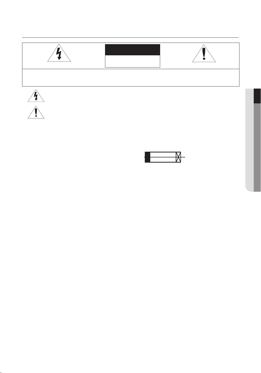
safety information
CAUTION
RISK OF ELECTRIC SHOCK.
DO NOT OPEN
CAUTION:
WARNING
To reduce the risk of fi re or electric shock, do not expose this appliance to rain or moisture.
•
To prevent injury, this apparatus must be securely attached to the fl oor/wall in accordance with the installation instructions.
•
- Do NOT use power sources other than Class 2 power source.
- REPLACE WITH SAME TYPE 250V T3.15AL FUSE(F1)
WARNING
Be sure to use only the standard adapter that is specifi ed in the specifi cation sheet.
1.
Using any other adapter could cause fi re, electrical shock, or damage to the product.
Incorrectly connecting the power supply or replacing battery may cause explosion, fi re, electric shock, or
2.
damage to the product.
Do not connect multiple cameras to a single adapter. Exceeding the capacity may cause abnormal heat
3.
generation or fi re.
Securely plug the power cord into the power receptacle. Insecure connection may cause fi re.
4.
When installing the camera, fasten it securely and fi rmly. The fall of camera may cause personal injury.
5.
Do not place conductive objects (e.g. screwdrivers, coins, metal parts, etc.) or containers fi lled with water
6.
on top of the camera. Doing so may cause personal injury due to fi re, electric shock, or falling objects.
Do not install the unit in humid, dusty, or sooty locations. Doing so may cause fi re or electric shock.
7.
If any unusual smells or smoke come from the unit, stop using the product. In such case, immediately
8.
disconnect the power source and contact the service center. Continued use in such a condition may cause
fi re or electric shock.
If this product fails to operate normally, contact the nearest service center. Never disassemble or modify this product
9.
in any way. (SAMSUNG is not liable for problems caused by unauthorized modifi cations or attempted repair.)
When cleaning, do not spray water directly onto parts of the product. Doing so may cause fi re or electric shock.
10.
TO REDUCE THE RISK OF ELECTRIC SHOCK, DO NOT REMOVE COVER (OR BACK) NO USER
SERVICEABLE PARTS INSIDE. REFER SERVICING TO QUALIFIED SERVICE PERSONNEL.
This symbol indicates that dangerous voltage consisting a risk of electric shock is present within
this unit.
This symbol indicates that there are important operating and maintenance instructions in the
literature accompanying this unit.
● SAFETY INFORMATION
CAUTION - Danger of explosion if battery is incorrectly replaced. Replace only with the same or equivalent type.
CAUTION
Do not drop objects on the product or apply strong blows to it. Keep away from a location subject to
1.
excessive vibration or magnetic interference.
Do not install in a location subject to high temperature (over 55°C), low temperature (below -50°C), or high
2.
humidity. Doing so may cause fi re or electric shock.
If you want to relocate the already installed product, be sure to turn off the power and then move or reinstall it.
3.
Remove the power plug from the outlet when there is a lighting storm. Neglecting to do so may cause fi re
4.
or damage to the product.
Keep out of direct sunlight and heat radiation sources. It may cause fi re.
5.
English - 3
safety information
Install it in a place with good ventilation.
6.
Avoid aiming the camera directly towards extremely bright objects such as sun, as this may damage the
7.
CCD image sensor.
Apparatus shall not be exposed to dripping or splashing and no objects fi lled with liquids, such as vases,
8.
shall be placed on the apparatus.
Do not expose the camera to radioactivity. Radioactivity exposure may damage the CCD.
9.
FCC Statement
This device complies with part 15 of the FCC Rules. Operation is subject to the following two conditions :
This device may not cause harmful interference, and
1)
This device must accept any interference received including interference that may cause undesired operation.
2)
CAUTION
This equipment has been tested and found to comply with the limits for a Class A digital device, pursuant
to part 15 of FCC Rules. These limits are designed to provide reasonable protection against harmful
interference when the equipment is operated in a commercial environment.
This equipment generates, uses, and can radiate radio frequency energy and, if not installed and used
in accordance with the instruction manual, may cause harmful interference to radio communications.
Operation of this equipment in a residential area is likely to cause harmful interference in which case the
user will be required to correct the interference at his own expense.
IC Compliance Notice
This Class A digital apparatus meets all requirements of the Canadian Interference.-Causing
Equipment Regulations of ICES-003.
Correct Disposal of This Product (Waste Electrical & Electronic Equipment)
(Applicable in the European Union and other European countries with separate collection systems)
This marking on the product, accessories or literature indicates that the product and its electronic accessories
(e.g. charger, headset, USB cable) should not be disposed of with other household waste at the end of
their working life. To prevent possible harm to the environment or human health from uncontrolled waste
disposal, please separate these items from other types of waste and recycle them responsibly to promote the
sustainable reuse of material resources.
Household users should contact either the retailer where they purchased this product, or their local
government office, for details of where and how they can take these items for environmentally safe recycling.
Business users should contact their supplier and check the terms and conditions of the purchase contract.
This product and its electronic accessories should not be mixed with other commercial wastes for disposal.
Correct disposal of batteries in this product
(Applicable in the European Union and other European countries with separate battery return systems.)
This marking on the battery, manual or packaging indicates that the batteries in this product should not be
disposed of with other household waste at the end of their working life. Where marked, the chemical symbols
Hg, Cd or Pb indicate that the battery contains mercury, cadmium or lead above the reference levels in EC
Directive 2006/66. If batteries are not properly disposed of, these substances can cause harm to human
health or the environment.
To protect natural resources and to promote material reuse, please separate batteries from other types of
waste and recycle them through your local, free battery return system.
CAUTION
RISK OF EXPLOSION IF BATTERY IS REPLACED BY AN INCORRECT TYPE.
DISPOSE OF USED BATTERIES ACCORDING TO THE INSTRUCTIONS
4_ safety information
important safety instructions
Read these instructions.
1.
Keep these instructions.
2.
Heed all warnings.
3.
Follow all instructions.
4.
Clean only with dry cloth.
5.
Do not block any ventilation openings. Install in accordance with the manufacturer’s instructions.
6.
Do not install near any heat sources such as radiators, heat registers, or other apparatus (including
7.
amplifi ers) that produce heat.
Do not defeat the safety purpose of the polarized or grounding-type plug.
8.
A polarized plug has two blades with one wider than the other. A grounding type plug has two blades and
a third grounding prong. The wide blade or the third prong is provided for your safety. If the provided plug
does not fi t into your outlet, consult an electrician for replacement of the obsolete outlet.
Protect the power cord from being walked on or pinched particularly at plugs, convenience receptacles,
9.
and the point where they exit from the apparatus.
Only use attachments/accessories specifi ed by the manufacturer.
10.
Use only with the cart, stand, tripod, bracket, or table specifi ed by the manufacturer, or
11.
sold with the apparatus. When a cart is used, use caution when moving the cart/
apparatus combination to avoid injury from tip-over.
● IMPORTANT SAFETY INSTRUCTIONS
Unplug this apparatus during lightning storms or when unused for long periods of time.
12.
When a cart is used, use caution when moving the cart/apparatus combination to
avoid injury from tip-over.
Refer all servicing to qualifi ed service personnel. Servicing is required when the apparatus has been
13.
damaged in any way, such as powersupply cord or plug is damaged, liquid has been spilled or objects
have fallen into the apparatus, the apparatus has been exposed to rain or moisture, does not operate
normally, or has been dropped.
Apparatus shall not be exposed to dripping or splashing and no objects fi lled with liquids, such
as vases, shall be placed on the apparatus
WARNING
To prevent injury, this apparatus must be securely attached to the fl oor/wall in accordance with the
installation instructions.
English - 5

CAUTION
These servicing instructions are for use by qualifi ed service personnel only. To reduce the risk of electric
shock, do not perform any servicing other than that contained in the operating instructions unless you are
qualifi ed to do so.
DETAILED WARNINGS AND CAUTIONS
y
Avoid operating the camera for long durations under high temperatures and in high humidity. Excessive
heat can shorten the lifespan of the camera components.
y
Do not install or place the camera near any heat sources.
y
Subjecting the dome cover to physical shock may damage the camera and cause water leakage into it.
y
Do not place the camera facing direct sunlight or other intense light sources. Strong lights such as
spotlights can cause distortions—blooming and smear—as well as discolorations on the screen by
heating up the color fi lter of the camera. They also may cause internal refl ections of the camera, leading
to operational malfunctions.
y
Do not drop the camera or subject it to physical shock or vibration; this can cause serious damage to the
camera.
y
When installing the camera near a power line, make sure to keep at least 1 meter distance from the
power line, or earth an additional metal pipe to separate the camera from the power source.
y
Install this camera on the ceiling. Installing it on the ground or a unleveled location may cause product
malfunctions and shorten its lifespan.
y
Avoid installing and operating the camera in the following places.
Places whose temperature exceed the camera’s recommended range.
-
(Indoor : -10ºC ~ 55ºC, Environmental : -50ºC~ 55ºC)
Places where drastic temperature changes occur: e.g. Near an air conditioner.
-
Places that are exposed to steam, oil, and infl ammable substances: e.g. Inside a kitchen.
-
-
Places that are exposed to radioactivity, X-rays, strong electric waves, and electro-magnetic waves.
-
Places that are exposed to outdoor air contaminants: e.g. Dust and car exhaust.
-
Places in high humidity.
-
Places that are exposed to corrosive gas: e.g. Next to the sea.
y
Smeared and dusty dome covers decrease the picture and video quality. Clean the dome cover and
camera lens on a regular basis.
y
Remove the plastic wrap on the dome cover only after the camera installation is complete.
y
This camera is not equipped with a power switch. Plug in the camera only after the installation is
complete.
6_ important safety instructions

CAUTIONS FOR OPERATING TEMPERATURE (FOR ENVIRONMENTAL MODELS)
The camera cannot operate properly at temperatures lower than -50°C.
1.
If the product is kept at a low temperature, it may take a max of 2 hours to warm up for normal
2.
operation.
If the camera was turned on after being left at temperatures lower than -50°C for a long duration:
3.
If the internal temperature is lower than -20°C, the camera does not transmit video signals and
-
displays a black screen along with the "Wait to warm up(xx Left)" message, instead of operating
properly.
If the internal temperature is higher than -20°C and lower than -10°C, the "Wait to warm up(xx Left)"
-
message disappears as the camera resets itself and enters the operation mode.
However, only manual P/T operation is in effect while the Sequence and Turbo commands are
limited in use.
If the internal temperature is higher than -10°C, the camera activates all Sequence and Turbo
-
commands.
The speed of the horizontal/vertical rotation will be deteriorated than normal at below -10C degrees
4.
for the indoor model, and at below -40C degrees for the environmental model.
5.
If the heater malfunctions, a message appears as follows.
-
"Please Check Heater System"
-
If this message appears, turn off the camera and call where you bought.
● IMPORTANT SAFETY INSTRUCTIONS
Samsung Techwin cares for the environment at all product manufacturing stages to
preserve the environment, and is taking a number of steps to provide customers with
more environment-friendly products.The Eco mark represents Samsung Techwin’s
will to create environment-friendly products, and indicates that the product satisfies
the EU RoHS Directive.
English - 7

contents
INTRODUCTION
9
CONNECTION &
INSTALLATION
14
SETUP
42
9 Features
11 What’s included
12
Component Names and Functions (Indoor Model)
13 Component Names and Functions
(Environmental model)
14 Camera Wiring Interface Board
15 Camera and Appliances Wiring Diagram
17
How to Set Up Protocols and ID DIP Switches
18 Communication Protocol DIP Switch
Settings (SW2)
21 Camera ID DIP Switch Settings (SW1)
29 Preparing Adapter and Cables
30 Product Confi gurations
31 Preparing & Installing Camera Bracket
32 Optional Accessories for Installation
35
On-Ceiling Mount Type Installation Example
38
Example of installing an Environmental model
42 Interface Symbols
43 Using and setting the menus
44 OSD Menu Chart
45 Camera Setup
55 Sequence Setting
65 P/T Setting
73 OSD Setting
74 Alarm Setting
77 Initialize
78 Password setting
78 Status
TROUBLESHOOTING
PRODUCT SPECIFICATIONS
8_ contents
79 Troubleshooting
79
83 Product Specifi cations
85 Dimensions
83

introduction
FEATURES
y
A/F 37x/27x Optical Zoom
The built-in 37x / 27x optical zoom lens with auto-focus is combined with a 16x digital zoom,
providing a maximum of 592/432 zoom.
y
Versatile protocols and coaxial communication
RS-422/485, Coaxial communication methods are supported.
RS-422/485 (10 species) : Auto Detected, SAMSUNG-T, SAMSUNG-E, Pelco (D/P), Panasonic, Vicon,
-
Honeywell, AD, GE, BOSCH
Coaxial Communications : Pelco Coaxitron (Camera ID DIP switches (SW1) are all positioned to OFF)
-
y
Wide Range Auto Security Functions
Multiple Preset Function Saving : Up to 12 camera image properities can be saved individually to provide
-
high quality pictures.
Image Holding : When moving in a group tour, the screen appears in a still image until the movement is
-
complete, thus reducing the optical fatigue of the observer.
PTZ Trace : Patterns operated with the joystick can be saved and replayed by users.
-
Swing : Using the Swing function commands the camera to move between 2 selected locations, monitoring
-
the route.
● INTRODUCTION
Group Search : Maximum 128 Preset positions are toured in order.
-
Tour Search : Maximum 6 Group Search functions are toured in order.
-
y
Digital Flip
The Digital Flip function is useful to monitor moving objects or people passing directly under the
camera. When an object or a person passes directly under the camera, its tilt motor follows the
object or person over 90 degrees to the other side of the tilt area without panning. The screen
inversion starts to occur at 90 degrees or higher is digitally adjusted.
y
Smart P/T
The Smart P/T function automatically adjusts the control speed of the Pan and Tilt functions
according to the current zoom ratio. It is useful to adjust the functions manually for detailed controls
when monitoring at high zoom ratios.
y
Day & Night
With its daytime & nighttime switch and Sens-Up functions based on the ICR (Infrared Cut fi lter
Removal) method, the camera provides high quality pictures regardless of whether it is day or night.
Sens-Up increases the CCD sensitivity by electrically extending the camera’s exposure time.
-
Day & Night enables you to select between color and B/W modes depending on the lighting conditions.
-
y
Highly durable built-in housing
This IP66-rated built-in housing is easy to install, and protects the product from a full range of harsh
outside conditions. The high performance built-in fan/heater enables the product to operate under
extreme temperatures between -50°C~ 55°C.
English - 9

introduction
y
Preset Position Saving and Loading
Up to 255 preset positions can be set. Using this function saves and brings up the camera feed of
a selected monitoring location.
y
Camera Backup
This is to back up the camera’s sequence information and presets. This is useful when the camera
or its install base are damaged or malfunctions occur.
y
Area Masking
If a monitoring location includes a highly private area, the area can be selectively masked on the
screen.
y
Model Specifi cations
SCP-2XX3H
Environmental Model
Zoom Factor
37: 37 Zoom Lens / 27: 27 Zoom Lens
10_ introduction
WHAT’S INCLUDED
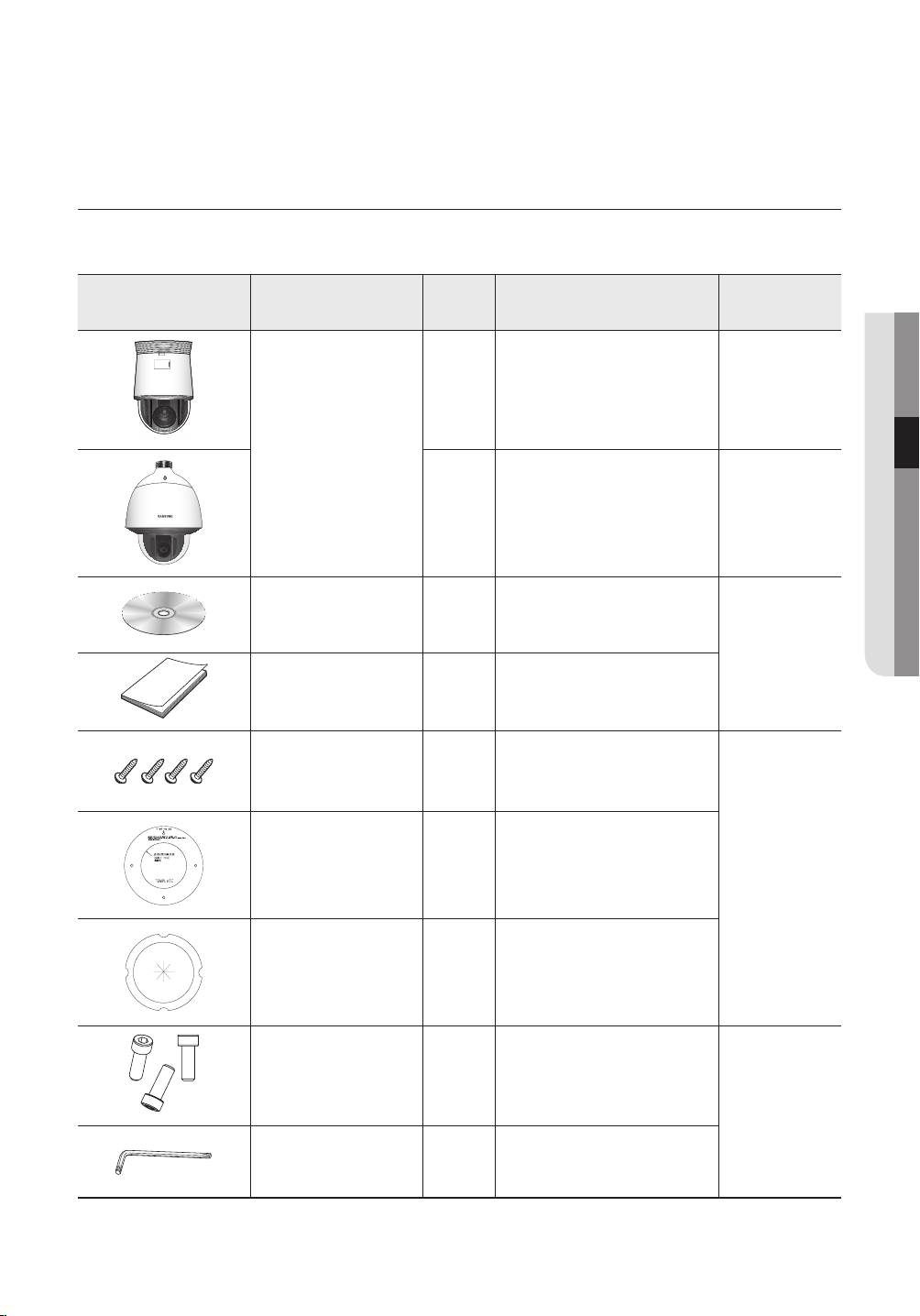
Check if the following items are included in the product package.
Appearance Item Name Quantity Description
1 - Indoor Model
Main Body
1-
CD Manual (Optional) 1 Multilingual User Manual
User Manual 1 English User Manual
Fixing Screw 4
If mounting the install base on the
ceiling
Applicable
Model
Environmental
Model
All
● INTRODUCTION
If determining the installation
Installation Template 1
Insulation Sheet 1
Hexagon screw 3
L Wrench 1
Ú
For classification of the indoor and environmental models, refer to page 10.
point before mounting the install
base on the ceiling
In the case of installing the
camera at highly humid place
Used for attaching the installation
base to the camera
Used for fixing the installation
base after attaching it to the
camera
Indoor Model
Environmental
Model
English - 11
introduction
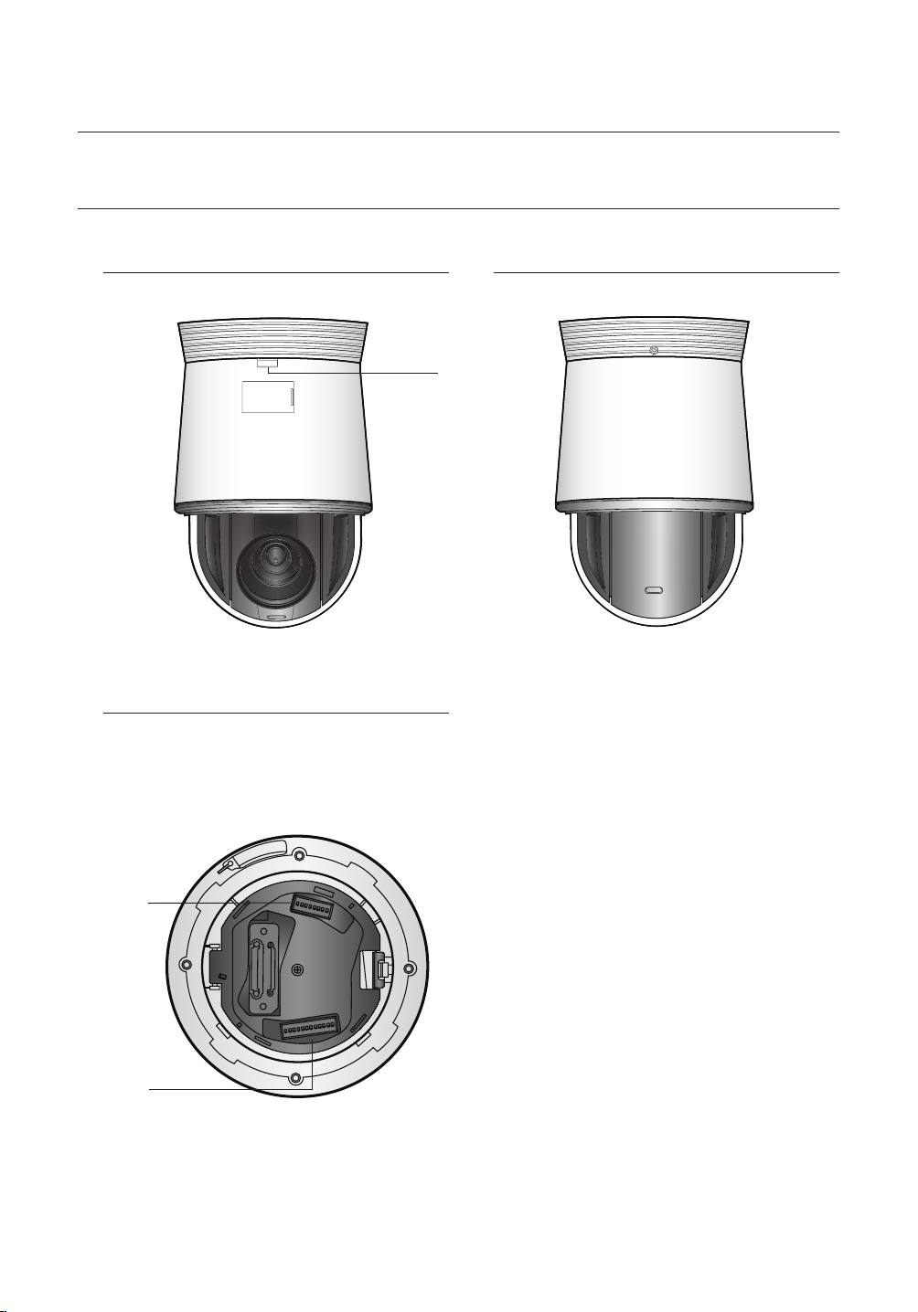
COMPONENT NAMES AND FUNCTIONS (INDOOR MODEL)
Front Back
➊
Install base
➋
➌
❶
Unlock Button
0/
0/
➋
SW1: ID DIP Switch
➌
SW2: Communication DIP Switch
Ú For the DIP switch settings, please refer to the
“Installing Your Camera” on Page 17~21.
12_ introduction
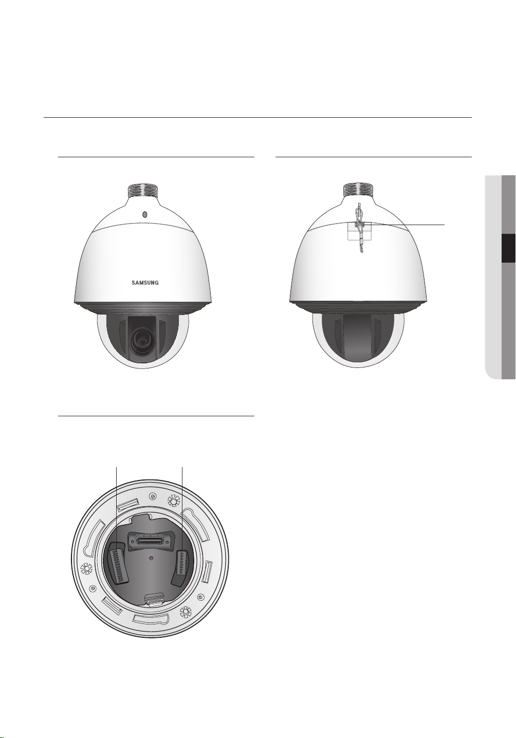
COMPONENT NAMES AND FUNCTIONS(ENVIRONMENTAL MODEL)
Front Back
● INTRODUCTION
➊
Install base
➋
➌
➊ Safety Wire Holder
➋ SW2: Communication DIP Switch
➌ SW1: ID DIP Switch
Ú For the DIP switch settings, please refer to the
“Installing Your Camera” on Page 17~21.
English - 13
connection & installation
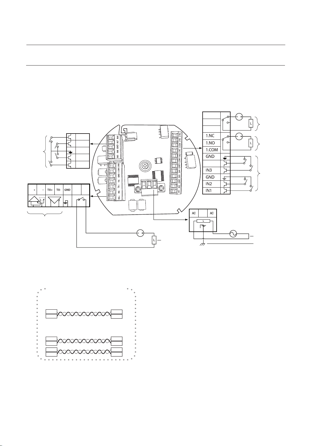
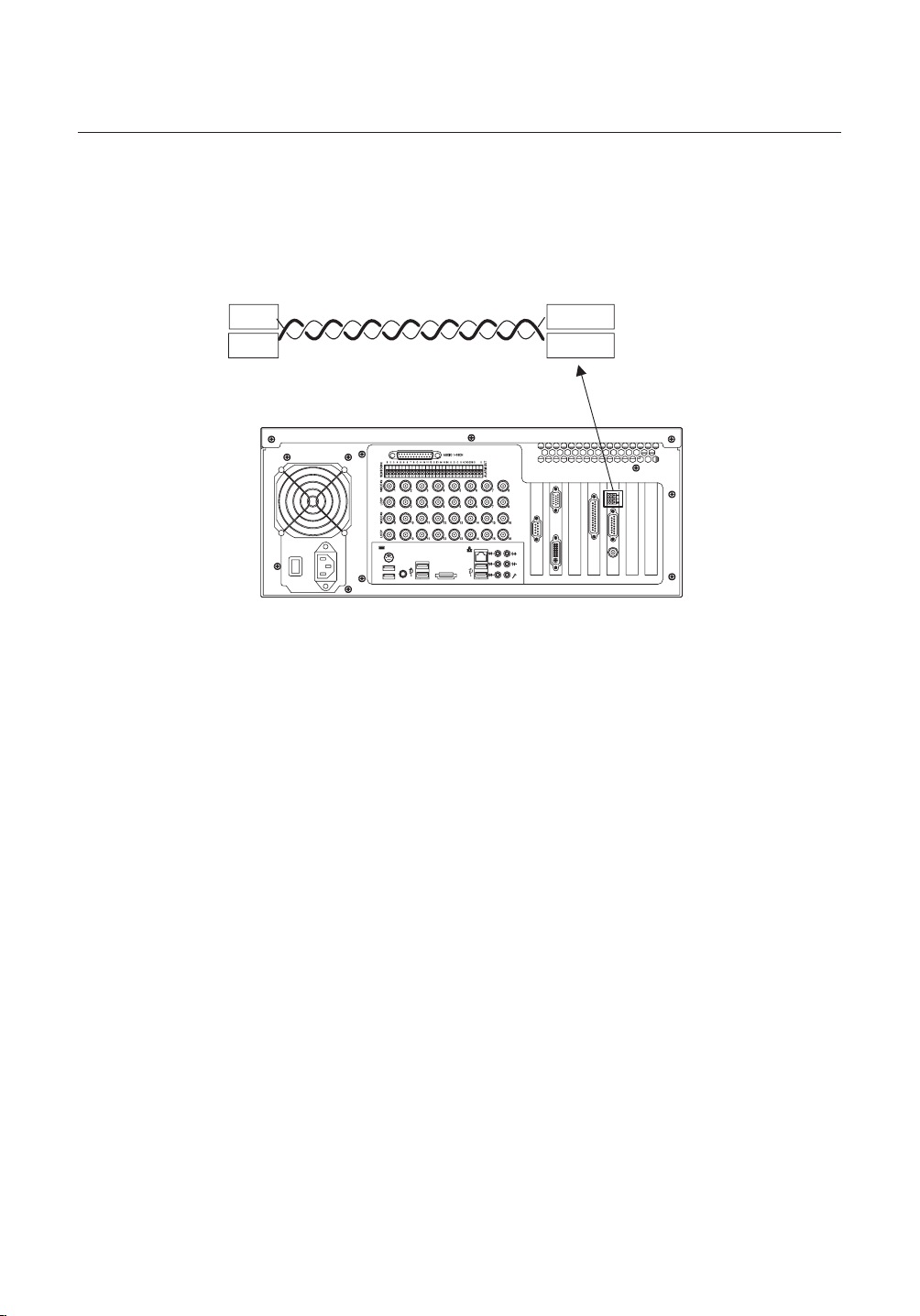
CAMERA WIRING INTERFACE BOARD
For the camera wiring, please refer to the picture below.
(When using coaxial communication, a separate control signal connection is not required.)
Alarm/AUX
2.NC
2.NO
2.COM
3.COM
IN8
IN7
GND
IN6
IN5
IN4
3.NO
Power Supply
FG
AC24V 2.5A
Alarm/
AUX
Output 3
Alarm
Input
5~8
Communications and Alarm/AUX
RX RX
Refer to the below Control
Signal Connection chart
Alarm/
AUX Output 2
Alarm/
AUX Output 1
Alarm Input
1~4
Power Input
Ground
Control Signal Connection
• RS485 Communications
Camera
RX+
RX-
• RS422 Communications
Camera
RX+
RX-
TX+
TX-
The max voltage and capacity of the Alarm OUT/AUX OUT ports are 30VDC/2A and 24VAC/2.5A, respectively.
M
Connecting the power connector and GND incorrectly to the NC/NO and COM ports may cause a short circuit and fi re,
damaging the camera.
14_
connection & installation
Controller
or DVR
TXD+
TXD-
Controller
or DVR
TXD+
TXD-
RXD+
RXD-
Ú
After connecting the power cable by
separating the power connector from the
terminal, make the connection between
terminal and connector by using a bolt.
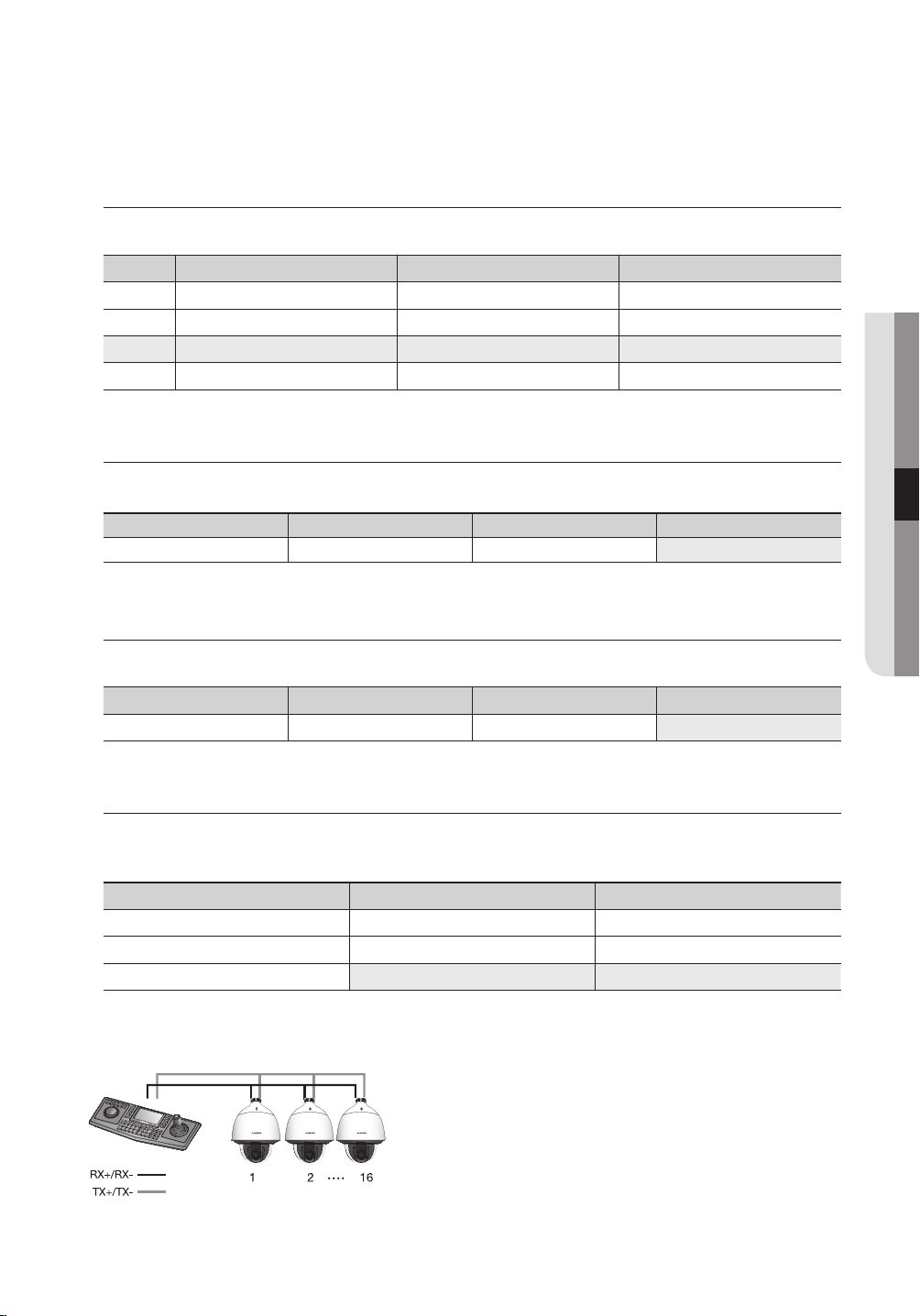
CAMERA AND APPLIANCES WIRING DIAGRAM
Connecting with Samsung Techwin’s “Stand Alone DVR”
y
RS-485 :
Camera
RX+
y
RS-422 :
Camera
RX+
TX+
RX-
RX-
TX-
Stand Alone DVR
T(TXD)+
T(TXD)-
Stand Alone DVR
T(TXD)+
T(TXD)-
R(RXD)+
R(TXD)-
Connecting with the Samsung Techwin Controller SPC-6000
y
RS-485 :
● CONNECTION & INSTALLATION
Camera
y
RS-422 :
Camera
RX+
RX-
TX+
TX-
RX+
RX-
TXD+
TXD-
TX RX TX RX
+- +- +- +-
RXD+
RXD-
TXD+
TXD-
TX RX TX RX
+- +- +- +-
G
C
A
M
1
6
7
G
M
E
N
U
S
E
A
R
C
H
MU
L
T
I
R
E
C
M
O
N
P
T
Z
2
3
4
8
9
M
E
N
U
P
R
E
S
E
T
G
R
O
U
P
D
V
R
TR
M
A
T
C
X
K
S
E
T
U
P
FU
N
C
5
E
N
T
E
E
R
S
C
C
L
O
S
E
O
P
E
N
0
NE
A
R
F
A
R
W
I
D
E
TE
L
E
<Controller>
English - 15
connection & installation
To connect to Samsung PC DVR
y
RS-485 :
Camera
RX+
RX-
PC DVR
16_
connection & installation
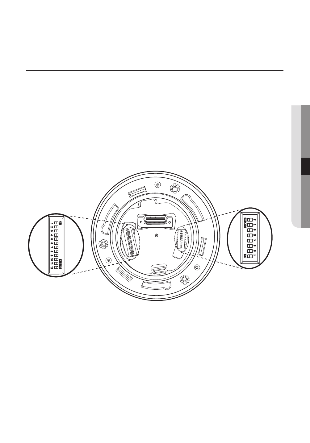
HOW TO SET UP PROTOCOLS AND ID DIP SWITCHES
You can control various settings of the camera system using the Communication and ID DIP switches.
Before installing the product, please set up the DIP switches according to the installation environment.
Remove the install base from the camera body and place the part to be headed to the lower end as
1.
shown in the fi gure.
2.
Set the switches according to your installation environment. For more detailed setup information, please refer
to the chart on the next page.
3.
The camera may malfunction if the switches are not fully turned On/Off; please double check the switches
before fi nishing setup.
Communication Protocol
DIP Switch(SW2)
● CONNECTION & INSTALLATION
Camera ID DIP Switch(SW1)
English - 17
connection & installation
COMMUNICATION PROTOCOL DIP SWITCH SETTINGS (SW2)
ON
SW2
SW2 Pin No. Purpose
1 ~ 4 Protocol Settings
5~6 Baud Rate Settings
7 Transfer Method (RS-485/422) Settings
8 Response Mode Settings
9~10 Backup Mode Settings
11~12 Termination Settings
ON
OFF
Protocol Settings
Select a communication protocol for the camera.
No Protocol SW2-#1 SW2-#2 SW2-#3 SW2-#4
1 Auto Detected OFF OFF OFF OFF
2 Samsung-T OFF OFF OFF ON
3 Samsung-E OFF OFF ON OFF
4 Pelco-D OFF OFF ON ON
5 Pelco-P OFF ON OFF OFF
6 Panasonic OFF ON OFF ON
7 Vicon OFF ON ON OFF
8 Honeywell OFF ON ON ON
9 AD ON OFF OFF OFF
10 GE ON OFF OFF ON
11 Bosch ON OFF ON OFF
18_
connection & installation
Baud Rate Settings
Select the transfer speed of a selected communication protocol.
No Baud Rate (BPS) SW2-#5 SW2-#6
1 2,400 ON ON
2 4,800 ON OFF
3 9,600 OFF OFF
4 19,200 OFF ON
Communication Method Settings
Select a communication method for the camera.
Function ON OFF
SW2- #7 Transfer Mode Switch RS-422 (4Wire) RS-485 (2Wire)
Communication Response Settings
Select a communication response method for the camera and controller: Response or No Response.
Function ON OFF
SW2- #8 Response Mode Switch Response No Response
● CONNECTION & INSTALLATION
Termination Settings
To prevent the attenuation of communication signals between the camera and controller, the items at
the end of line must be set up with the termination settings.
Camera Input Position
Termination of Longest Path (RS-422)
Termination of Longest Path (RS-485)
On the Path OFF OFF
y
Example of terminal setting
SW2- #11 SW2- #12
ON ON
ON OFF
If using RS-422, SW2-#11: ON /SW2-#12: ON for camera 16
Ú
If using RS-485, SW2-#11: ON / SW2-#12: OFF for camera 16
Ú
English - 19

connection & installation
Camera Backup Settings
These settings are useful when the camera or its install base are damaged or malfunctions occur.
When replacing the camera or its install base, you can transfer existing presets and sequence
information to the replacement using these settings.
Backup Function
Backup(IBD) OFF OFF
Backup(DIB) ON OFF
Backup Disable - ON
Backup(IBD) : Enables transferring the current camera's sequence information to a new camera.
-
Backup(DIB) : Enables transferring the current camera's sequence information to a new install base.
-
Ú
IB: Install base, D: Dome Camera
■
[Current Time] is not backed up from install base to camera.
This model is shipped from the factory with all the communication dip switches (SW2) set to OFF, and the default values
I
are shaded as shown in the setting table.
If you want to use a third-party controller for controlling the camera, contact us at the call center or visit our website for
details.
AD Protocol Control Method
Input Camera OSD: 3+Auxiliary On
1.
Output Camera OSD: 3+Auxiliary Off
2.
Enter: IRIS Open
3.
ESC: IRIS Close
4.
For more information about the protocols, refer to our offi cial website.
http://www.samsungtechwin.com/
SW2- #9 SW2- #10
20_
connection & installation
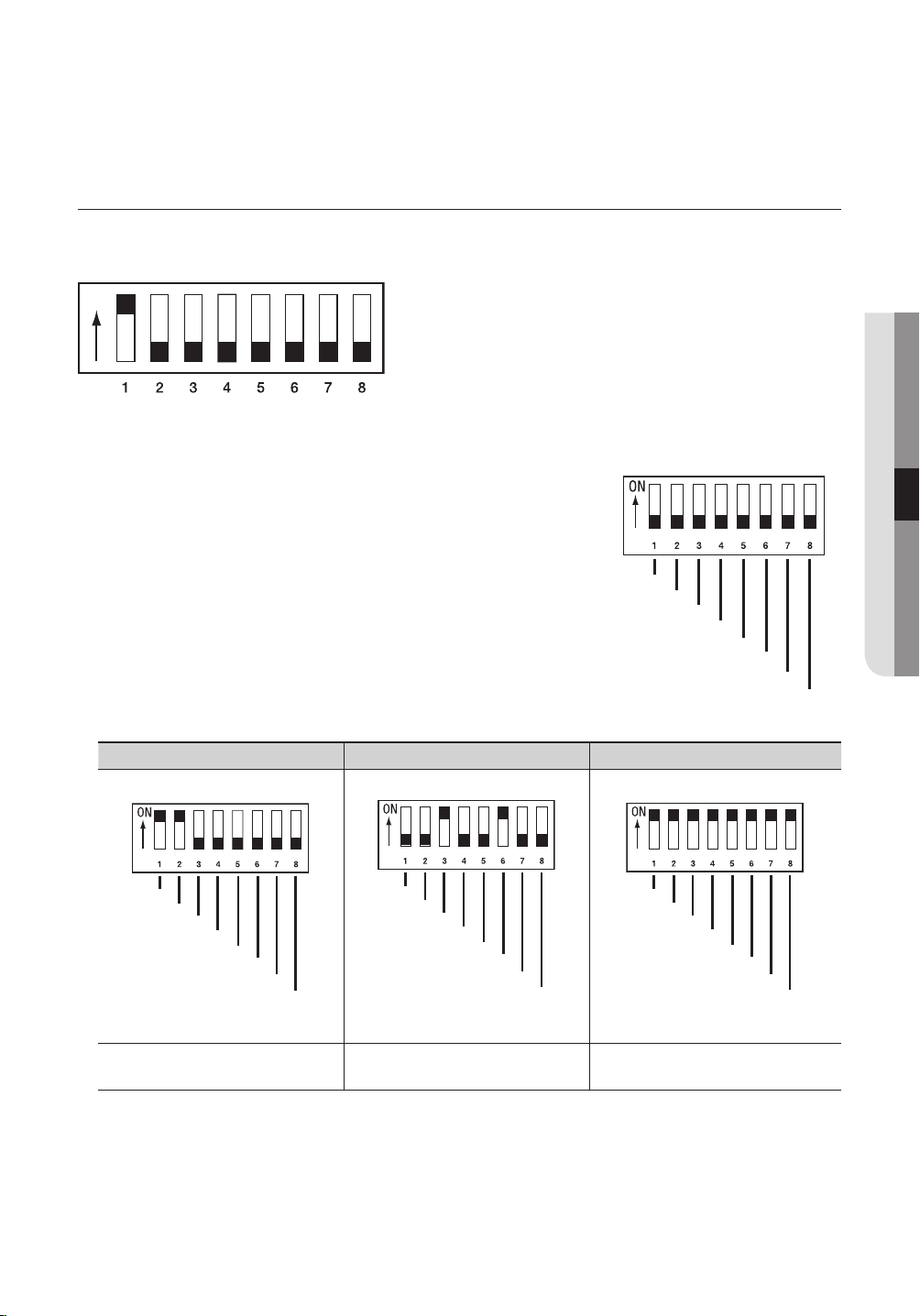
CAMERA ID DIP SWITCH SETTINGS (SW1)
Assign a unique number for each camera to identify itself from others.
ON
SW1
The switch is set to “ID: 1” by default, and 7 switches other than
1.
ON
OFF
switch 1 are all set to OFF.
Each switch has a unique value, and the board ID is the sum of
2.
the values of the switches.
Refer to the example below for the board ID.
Example 1
Example 2 Example 3
● CONNECTION & INSTALLATION
ON
OFF
1+2 = 3 (Board ID = 3) 4+32 = 36 (Board ID = 36)
Use a unique ID for each Camera.
M
In coaxial communication systems, the camera will work normally only if the Camera ID DIP switches (SW1) are all
positioned to OFF.
1+2+4+8+16+32+64+128
= 255 (Board ID = 255 )
English - 21

connection & installation
y
Camera ID Chart
ID SW1-#1 SW1-#2 SW1-#3 SW1-#4 SW1-#5 SW1-#6 SW1-#7 SW1-#8
COAX OFF OFF OFF OFF OFF OFF OFF OFF
1 ON OFF OFF OFF OFF OFF OFF OFF
2 OFF ON OFF OFF OFF OFF OFF OFF
3 ON ON OFF OFF OFF OFF OFF OFF
4 OFF OFF ON OFF OFF OFF OFF OFF
5 ON OFF ON OFF OFF OFF OFF OFF
6 OFF ON ON OFF OFF OFF OFF OFF
7 ON ON ON OFF OFF OFF OFF OFF
8 OFF OFF OFF ON OFF OFF OFF OFF
9 ON OFF OFF ON OFF OFF OFF OFF
10 OFF ON OFF ON OFF OFF OFF OFF
11 ON ON OFF ON OFF OFF OFF OFF
12 OFF OFF ON ON OFF OFF OFF OFF
13 ON OFF ON ON OFF OFF OFF OFF
14 OFF ON ON ON OFF OFF OFF OFF
15 ON ON ON ON OFF OFF OFF OFF
16 OFF OFF OFF OFF ON OFF OFF OFF
17 ON OFF OFF OFF ON OFF OFF OFF
18 OFF ON OFF OFF ON OFF OFF OFF
19 ON ON OFF OFF ON OFF OFF OFF
20 OFF OFF ON OFF ON OFF OFF OFF
21 ON OFF ON OFF ON OFF OFF OFF
22 OFF ON ON OFF ON OFF OFF OFF
23 ON ON ON OFF ON OFF OFF OFF
24 OFF OFF OFF ON ON OFF OFF OFF
25 ON OFF OFF ON ON OFF OFF OFF
26 OFF ON OFF ON ON OFF OFF OFF
27 ON ON OFF ON ON OFF OFF OFF
28 OFF OFF ON ON ON OFF OFF OFF
29 ON OFF ON ON ON OFF OFF OFF
30 OFF ON ON ON ON OFF OFF OFF
31 ON ON ON ON ON OFF OFF OFF
32 OFF OFF OFF OFF OFF ON OFF OFF
33 ON OFF OFF OFF OFF ON OFF OFF
34 OFF ON OFF OFF OFF ON OFF OFF
35 ON ON OFF OFF OFF ON OFF OFF
36 OFF OFF ON OFF OFF ON OFF OFF
37 ON OFF ON OFF OFF ON OFF OFF
22_
connection & installation

ID SW1-#1 SW1-#2 SW1-#3 SW1-#4 SW1-#5 SW1-#6 SW1-#7 SW1-#8
38 OFF ON ON OFF OFF ON OFF OFF
39 ON ON ON OFF OFF ON OFF OFF
40 OFF OFF OFF ON OFF ON OFF OFF
41 ON OFF OFF ON OFF ON OFF OFF
42 OFF ON OFF ON OFF ON OFF OFF
43 ON ON OFF ON OFF ON OFF OFF
44 OFF OFF ON ON OFF ON OFF OFF
45 ON OFF ON ON OFF ON OFF OFF
46 OFF ON ON ON OFF ON OFF OFF
47 ON ON ON ON OFF ON OFF OFF
48 OFF OFF OFF OFF ON ON OFF OFF
49 ON OFF OFF OFF ON ON OFF OFF
50 OFF ON OFF OFF ON ON OFF OFF
51 ON ON OFF OFF ON ON OFF OFF
52 OFF OFF ON OFF ON ON OFF OFF
53 ON OFF ON OFF ON ON OFF OFF
54 OFF ON ON OFF ON ON OFF OFF
55 ON ON ON OFF ON ON OFF OFF
56 OFF OFF OFF ON ON ON OFF OFF
57 ON OFF OFF ON ON ON OFF OFF
58 OFF ON OFF ON ON ON OFF OFF
59 ON ON OFF ON ON ON OFF OFF
60 OFF OFF ON ON ON ON OFF OFF
61 ON OFF ON ON ON ON OFF OFF
62 OFF ON ON ON ON ON OFF OFF
63 ON ON ON ON ON ON OFF OFF
64 OFF OFF OFF OFF OFF OFF ON OFF
65 ON OFF OFF OFF OFF OFF ON OFF
66 OFF ON OFF OFF OFF OFF ON OFF
67 ON ON OFF OFF OFF OFF ON OFF
68 OFF OFF ON OFF OFF OFF ON OFF
69 ON OFF ON OFF OFF OFF ON OFF
70 OFF ON ON OFF OFF OFF ON OFF
71 ON ON ON OFF OFF OFF ON OFF
72 OFF OFF OFF ON OFF OFF ON OFF
73 ON OFF OFF ON OFF OFF ON OFF
74 OFF ON OFF ON OFF OFF ON OFF
75 ON ON OFF ON OFF OFF ON OFF
76 OFF OFF ON ON OFF OFF ON OFF
● CONNECTION & INSTALLATION
English - 23

connection & installation
ID SW1-#1 SW1-#2 SW1-#3 SW1-#4 SW1-#5 SW1-#6 SW1-#7 SW1-#8
77 ON OFF ON ON OFF OFF ON OFF
78 OFF ON ON ON OFF OFF ON OFF
79 ON ON ON ON OFF OFF ON OFF
80 OFF OFF OFF OFF ON OFF ON OFF
81 ON OFF OFF OFF ON OFF ON OFF
82 OFF ON OFF OFF ON OFF ON OFF
83 ON ON OFF OFF ON OFF ON OFF
84 OFF OFF ON OFF ON OFF ON OFF
85 ON OFF ON OFF ON OFF ON OFF
86 OFF ON ON OFF ON OFF ON OFF
87 ON ON ON OFF ON OFF ON OFF
88 OFF OFF OFF ON ON OFF ON OFF
89 ON OFF OFF ON ON OFF ON OFF
90 OFF ON OFF ON ON OFF ON OFF
91 ON ON OFF ON ON OFF ON OFF
92 OFF OFF ON ON ON OFF ON OFF
93 ON OFF ON ON ON OFF ON OFF
94 OFF ON ON ON ON OFF ON OFF
95 ON ON ON ON ON OFF ON OFF
96 OFF OFF OFF OFF OFF ON ON OFF
97 ON OFF OFF OFF OFF ON ON OFF
98 OFF ON OFF OFF OFF ON ON OFF
99 ON ON OFF OFF OFF ON ON OFF
100 OFF OFF ON OFF OFF ON ON OFF
101 ON OFF ON OFF OFF ON ON OFF
102 OFF ON ON OFF OFF ON ON OFF
103 ON ON ON OFF OFF ON ON OFF
104 OFF OFF OFF ON OFF ON ON OFF
105 ON OFF OFF ON OFF ON ON OFF
106 OFF ON OFF ON OFF ON ON OFF
107 ON ON OFF ON OFF ON ON OFF
108 OFF OFF ON ON OFF ON ON OFF
109 ON OFF ON ON OFF ON ON OFF
110 OFF ON ON ON OFF ON ON OFF
111 ON ON ON ON OFF ON ON OFF
112 OFF OFF OFF OFF ON ON ON OFF
113 ON OFF OFF OFF ON ON ON OFF
114 OFF ON OFF OFF ON ON ON OFF
115 ON ON OFF OFF ON ON ON OFF
24_
connection & installation

ID SW1-#1 SW1-#2 SW1-#3 SW1-#4 SW1-#5 SW1-#6 SW1-#7 SW1-#8
116 OFF OFF ON OFF ON ON ON OFF
117 ON OFF ON OFF ON ON ON OFF
118 OFF ON ON OFF ON ON ON OFF
119 ON ON ON OFF ON ON ON OFF
120 OFF OFF OFF ON ON ON ON OFF
121 ON OFF OFF ON ON ON ON OFF
122 OFF ON OFF ON ON ON ON OFF
123 ON ON OFF ON ON ON ON OFF
124 OFF OFF ON ON ON ON ON OFF
125 ON OFF ON ON ON ON ON OFF
126 OFF ON ON ON ON ON ON OFF
127 ON ON ON ON ON ON ON OFF
128 OFF OFF OFF OFF OFF OFF OFF ON
129 ON OFF OFF OFF OFF OFF OFF ON
130 OFF ON OFF OFF OFF OFF OFF ON
131 ON ON OFF OFF OFF OFF OFF ON
132 OFF OFF ON OFF OFF OFF OFF ON
133 ON OFF ON OFF OFF OFF OFF ON
134 OFF ON ON OFF OFF OFF OFF ON
135 ON ON ON OFF OFF OFF OFF ON
136 OFF OFF OFF ON OFF OFF OFF ON
137 ON OFF OFF ON OFF OFF OFF ON
138 OFF ON OFF ON OFF OFF OFF ON
139 ON ON OFF ON OFF OFF OFF ON
140 OFF OFF ON ON OFF OFF OFF ON
141 ON OFF ON ON OFF OFF OFF ON
142 OFF ON ON ON OFF OFF OFF ON
143 ON ON ON ON OFF OFF OFF ON
144 OFF OFF OFF OFF ON OFF OFF ON
145 ON OFF OFF OFF ON OFF OFF ON
146 OFF ON OFF OFF ON OFF OFF ON
147 ON ON OFF OFF ON OFF OFF ON
148 OFF OFF ON OFF ON OFF OFF ON
149 ON OFF ON OFF ON OFF OFF ON
150 OFF ON ON OFF ON OFF OFF ON
151 ON ON ON OFF ON OFF OFF ON
152 OFF OFF OFF ON ON OFF OFF ON
153 ON OFF OFF ON ON OFF OFF ON
154 OFF ON OFF ON ON OFF OFF ON
● CONNECTION & INSTALLATION
English - 25

connection & installation
ID SW1-#1 SW1-#2 SW1-#3 SW1-#4 SW1-#5 SW1-#6 SW1-#7 SW1-#8
155 ON ON OFF ON ON OFF OFF ON
156 OFF OFF ON ON ON OFF OFF ON
157 ON OFF ON ON ON OFF OFF ON
158 OFF ON ON ON ON OFF OFF ON
159 ON ON ON ON ON OFF OFF ON
160 OFF OFF OFF OFF OFF ON OFF ON
161 ON OFF OFF OFF OFF ON OFF ON
162 OFF ON OFF OFF OFF ON OFF ON
163 ON ON OFF OFF OFF ON OFF ON
164 OFF OFF ON OFF OFF ON OFF ON
165 ON OFF ON OFF OFF ON OFF ON
166 OFF ON ON OFF OFF ON OFF ON
167 ON ON ON OFF OFF ON OFF ON
168 OFF OFF OFF ON OFF ON OFF ON
169 ON OFF OFF ON OFF ON OFF ON
170 OFF ON OFF ON OFF ON OFF ON
171 ON ON OFF ON OFF ON OFF ON
172 OFF OFF ON ON OFF ON OFF ON
173 ON OFF ON ON OFF ON OFF ON
174 OFF ON ON ON OFF ON OFF ON
175 ON ON ON ON OFF ON OFF ON
176 OFF OFF OFF OFF ON ON OFF ON
177 ON OFF OFF OFF ON ON OFF ON
178 OFF ON OFF OFF ON ON OFF ON
179 ON ON OFF OFF ON ON OFF ON
180 OFF OFF ON OFF ON ON OFF ON
181 ON OFF ON OFF ON ON OFF ON
182 OFF ON ON OFF ON ON OFF ON
183 ON ON ON OFF ON ON OFF ON
184 OFF OFF OFF ON ON ON OFF ON
185 ON OFF OFF ON ON ON OFF ON
186 OFF ON OFF ON ON ON OFF ON
187 ON ON OFF ON ON ON OFF ON
188 OFF OFF ON ON ON ON OFF ON
189 ON OFF ON ON ON ON OFF ON
190 OFF ON ON ON ON ON OFF ON
191 ON ON ON ON ON ON OFF ON
192 OFF OFF OFF OFF OFF OFF ON ON
193 ON OFF OFF OFF OFF OFF ON ON
26_
connection & installation

ID SW1-#1 SW1-#2 SW1-#3 SW1-#4 SW1-#5 SW1-#6 SW1-#7 SW1-#8
194 OFF ON OFF OFF OFF OFF ON ON
195 ON ON OFF OFF OFF OFF ON ON
196 OFF OFF ON OFF OFF OFF ON ON
197 ON OFF ON OFF OFF OFF ON ON
198 OFF ON ON OFF OFF OFF ON ON
199 ON ON ON OFF OFF OFF ON ON
200 OFF OFF OFF ON OFF OFF ON ON
201 ON OFF OFF ON OFF OFF ON ON
202 OFF ON OFF ON OFF OFF ON ON
203 ON ON OFF ON OFF OFF ON ON
204 OFF OFF ON ON OFF OFF ON ON
205 ON OFF ON ON OFF OFF ON ON
206 OFF ON ON ON OFF OFF ON ON
207 ON ON ON ON OFF OFF ON ON
208 OFF OFF OFF OFF ON OFF ON ON
209 ON OFF OFF OFF ON OFF ON ON
210 OFF ON OFF OFF ON OFF ON ON
211 ON ON OFF OFF ON OFF ON ON
212 OFF OFF ON OFF ON OFF ON ON
213 ON OFF ON OFF ON OFF ON ON
214 OFF ON ON OFF ON OFF ON ON
215 ON ON ON OFF ON OFF ON ON
216 OFF OFF OFF ON ON OFF ON ON
217 ON OFF OFF ON ON OFF ON ON
218 OFF ON OFF ON ON OFF ON ON
219 ON ON OFF ON ON OFF ON ON
220 OFF OFF ON ON ON OFF ON ON
221 ON OFF ON ON ON OFF ON ON
222 OFF ON ON ON ON OFF ON ON
223 ON ON ON ON ON OFF ON ON
224 OFF OFF OFF OFF OFF ON ON ON
225 ON OFF OFF OFF OFF ON ON ON
226 OFF ON OFF OFF OFF ON ON ON
227 ON ON OFF OFF OFF ON ON ON
228 OFF OFF ON OFF OFF ON ON ON
229 ON OFF ON OFF OFF ON ON ON
230 OFF ON ON OFF OFF ON ON ON
231 ON ON ON OFF OFF ON ON ON
232 OFF OFF OFF ON OFF ON ON ON
● CONNECTION & INSTALLATION
English - 27
 Loading...