

Page 1

SCC-C7478
36x Smart Dome Camera
User’s Guide
ENG RUS
imagine the possibilities
Thank you for purchasing this Samsung product.
To receive more complete service,
please register your product at
www.samsung.com/global/register
POL TUR
CZE
Page 2

Safety information
CAUTION
RISK OF ELECTRIC SHOCK.
DO NOT OPEN
CAUTION: TO REDUCE THE RISK OF ELECTRIC SHOCK, DO NOT REMOVE REAR COVER. NO USER SERVICEABLE PARTS
INSIDE. REFER TO QUALIFIED SERVICE PERSONNEL..
This symbol indicates high voltage is present inside. It is dangerous to make any kind of
contact with any inside part of this product.
This symbol alerts you that important literature concerning operation and maintenance has
been included with this product.
WARNING
•
To prevent damage which may result in fi re or electric shock hazard, do not expose this appliance to rain or
moisture.
WARNING
1.
Be sure to use only the standard adapter that is specifi ed in the specifi cation sheet. Using any other adapter
could cause fi re, electrical shock, or damage to the product
2.
Incorrectly connecting the power supply or replacing battery may cause explosion, fi re, electric shock, or
damage to the product.
3.
Do not connect multiple cameras to a single adapter. Exceeding the capacity may cause abnormal heat
generation or fi re.
4.
Securely plug the power cord into the power receptacle. Insecure connection may cause fi re.
5.
When installing the camera, fasten it securely and fi rmly. A falling camera may cause personal injury.
6.
Do not place conductive objects (e.g. screwdrivers, coins, metal things, etc.) or containers fi lled with water
on top of the camera. Doing so may cause personal injury due to fi re, electric shock, or falling objects.
7.
Do not install the unit in humid, dusty, or sooty locations. Doing so may cause fi re or electric shock.
8.
If any unusual smells or smoke come from the unit, stop using the product. In such case, immediately
disconnect the power source and contact the service center. Continued use in such a condition may cause
fi re or electric shock.
9.
If this product fails to operate normally, contact the nearest service center. Never disassemble or modify
this product in any way. (SAMSUNG is not liable for problems caused by unauthorized modifi cations or
attempted repair.)
When cleaning, do not spray water directly onto parts of the product. Doing so may cause fi re or electric shock.
10.
If the camera is installed or rebooted after power failure when ambient temperature is below the freezing point,
11.
the dome cover is frosted. In this case, the frost will be disappeared after 3 hours after turning on the power.
(It is noted that lowest guaranteed operating temperature is -45º C (-49º F) without wind.)
2 – 36x SMART DOME CAMERA
Page 3

Safety information
CAUTION
Do not drop objects on the product or apply strong shock to it. Keep away from a location subject to
1.
excessive vibrationor magnetic interference.
Do not install in a location subject to high temperature (over 50°C), low temperature (below -10°C), or high
2.
humidity. Doing so may cause fi re or electric shock.
If you want to relocate the already installed product, be sure to turn off the power and then move or reinstall
3.
it.
Remove the power plug from the outlet when then there is a lightning. Neglecting to do so may cause fi re or
4.
damage to the product.
Keep out of direct sunlight and heat radiation sources. It may cause fi re.
5.
Install it in a place with good ventilation.
6.
Avoid aiming the camera directly towards extremely bright objects such as sun, as this may damage the
7.
CCD image sensor.
Apparatus shall not be exposed to dripping or splashing and no objects fi lled with liquids, such as vases,
8.
shall be placed on the apparatus.
The Mains plug is used as a disconnect device and shall stay readily operable at any time.
9.
ENG
English – 3
Page 4

Important Safety Instructions
Read these instructions.
1.
Keep these instructions.
2.
Heed all warnings.
3.
Follow all instructions.
4.
Do not use this apparatus near water.
5.
Clean only with dry cloth.
6.
Do not block any ventilation openings. Install in accordance with the manufacturer’s instructions.
7.
Do not install near any heat sources such as radiators, heat registers, or other apparatus (including amplifi ers) that
8.
produce heat.
Do not defeat the safety purpose of the polarized or grounding-type plug. A polarized plug has two blades with
9.
one wider than the other. A grounding type plug has two blades and a third grounding prong. The wide blade or
the third prong is provided for your safety. If the provided plug does not fi t into your outlet, consult an electrician
for replacement of the obsolete outlet.
Protect the power cord from being walked on or pinched particularly at plugs, convenience
10.
receptacles, and the point where they exit from the apparatus.
Only use attachments/accessories specifi ed by the manufacturer.
11.
Use only with cart, stand, tripod, bracket, or table specifi ed by the manufacturer, or sold
12.
with the apparatus.
Unplug this apparatus when a card is used. Use caution when moving the cart/ apparatus combination to avoid
13.
injury from tip-over.
Refer all servicing to qualifi ed service personnel. Servicing is required when the apparatus has been damaged in
14.
any way, such as powersupply cord or plug is damaged, liquid has been spilled or objects have fallen into the
apparatus, the apparatus has been exposed to rain or moisture, does not operate normally, or has been dropped.
4 – 36x SMART DOME CAMERA
Page 5

Contents
Introduction
Features 6
Product & Accessories 7
Parts Name & Functions 8
Installation
DIP Switch Setup 9
Installation using Mount Bracket 10
Cabling 13
Operation
Check points before operation 15
Preset and Pattern Function Pre-Check 15
AUTO CALIBRATION 15
Starting OSD Menu 15
Reserved Preset 15
Preset 16
Auto Pan 16
Pattern 16
Scan 16
Schedule 17
Other Functions 17
OSD Display of Main Screen 18
General Rules of Key Operation for Menu 18
ENG
How to use OSD Menu
Main Menu 19
System Information 19
Display Setup 19
PRIVACY ZONE MASK Setup 19
Motion Setup 20
Function Setup 21
PRESET Setup 22
Auto Pan Setup 23
Pattern Setup 23
Scan Setup 24
Schedule Setup 26
CAMERA SETUP 27
System Setup 28
System Initialize 30
Specifi cations
Specifi cations 31
Dimension 32
English – 5
Page 6

Introduction
FEATURES
Camera Specifi cations
❖
CCD Sensor : EX-view HADTM CCD
•
Zoom Magnifi cation : × 36 Optical Zoom, × 12
•
Digital Zoom (Max × 432 Zoom)
Wide Dynamic Range Function
•
Day & Night Function : ICR(IR Cut fi lter Removal)
•
Various Focus Mode : Auto Focus / Manual Focus
•
/ Semi-Auto Focus.
•
Independent or Global camera settings for each
Preset locations.
Powerful Pan/Tilt Functions
❖
•
Max. 360°/sec high speed Pan/Tilt Motion
•
Using Vector Drive Technology, Pan/Tilt motions
are accomplished in the shortest path. As a result,
time to target view is reduced dramatically and the
video on the monitor is very natural to watch.
•
Ultra low speed (0.05°/sec) enables operator
to locate camera to desired target view with
accuracy and ease.
•
Zoom-proportional pan/tilt speed helps operator
to move the camera easily.
Preset, Pattern, Auto Pan, Scan, Privacy
❖
Mask, Schedule and More…
MAX. 127 Presets are assignable. All of them
•
have independent characteristics such as White
Balance, Auto Exposure, Label, Alarm Input/
Output and so on.
Max. 8 set of Auto Pan can be stored. This
•
enables to move camera repetitively between two
preset positions with designated speed.
Max. 4 of Patterns can be recorded and played
•
back. This enables to move camera to follow any
trajectory operated by joystick as closely as possible.
Max. 8 set of Scan action can be stored.
•
This enables to move camera repetitively with
combination of Preset or Pattern or Auto Pan. A
Scan is composed of max. 20 entities of Preset/
Pattern/Auto Pans.
Max 8 Privacy Masks can be set up to protect
•
privacy of other people.
7 rules of Schedule can be assigned by day and
•
time. Appropriate actions (such as Home, Preset,
Scan, Pattern and Auto Pan) can be defi ned for
each rule. Also, it is possible to use Weekday and
All days to simplify the rule.
PTZ(Pan/Tilt/Zoom) Control
❖
With RS-485 communication, max. 255 of
•
cameras can be controlled at the same time.
•
Pelco-D/ Pelco-P/ Samsung protocol can be
selected as a control protocol in the current
version of fi rmware.
OSD(On Screen Display) Menu
❖
OSD menu is provided to display the status
•
of camera and to confi gure the functions
interactively.
The information such as Camera ID, Pan/Tilt/
•
Zoom/Direction, Alarm Input & Output, date/time,
current temperature and Preset can be displayed
on screen.
Each display item can be turned on or off
•
independently.
Alarm I/O Functions
❖
8 alarm sensor Inputs and 4 relay output are
•
available.
To reject external electric noise and shock
•
perfectly, alarm sensor Input is decoupled with
photo coupler.
The signal range of sensor input is from DC 5.0 to
•
12.0 volts to adopt various applications.
If an external sensor is activated, camera can be
•
set to move to the corresponding Preset position.
Relay outputs can be assigned to work with a
•
certain preset.
Reserved Presets for Special Purpose
❖
Most of camera settings are directly changed by
•
calling Reserved Presets, not entering into OSD
menu. For more information,refer to “Reserved
Presets”(page 15) in this manual.
6 – 36x SMART DOME CAMERA
Page 7

PRODUCT & ACCESSORIES
Product❖
Wall Mount Type Ceiling Mount Type
Accessories❖
Introduction
ENG
Hexagonal wrench Anchor bolts (4pcs) Water proof tape
Hole Template
User’s Guide Safety Cable
Housing Safety Cable
Hanger
English – 7
Page 8

Introduction
PARTS NAME & FUNCTIONS
SUN SHIELD & UPPER
HOUSING
PTZ MECHANISM
DOME SAFETY CABLE
FAN
HEATER
Dome Cover
•
Do not detach protection vinyl from dome cover
before fi nishing all installation process to protect
dome cover from scratches or dust.
In the dome cover, there are Fan and Heater to
remove moisture on the bubble dome.
Sunshield & Upper housing
•
Sunshield protect bubble dome cover from the sun
rays and rain fall from. In the sunshield, there is the
upper housing which will contain accommodate
PTZ mechanism. Also, the upper housing will be
connected to both mounting brackets and dome
cover.
FAN & HEATER CABLE
DOME COVER
INNER BOX
HOUSING SAFETY CABLE HANGER
Wall/Ceiling mount Bracket
•
These are used to install the camera on the wall or
ceiling and have junction box. The junction box of the
bracket accommodate inner box.
Inner box
•
The inner has many important roles of connection
box between camera and outside. Top of the box,
there are dip switches and terminal blocks for Power
supply, Video, Communication, Alarm Input/output.
8 – 36x SMART DOME CAMERA
Page 9
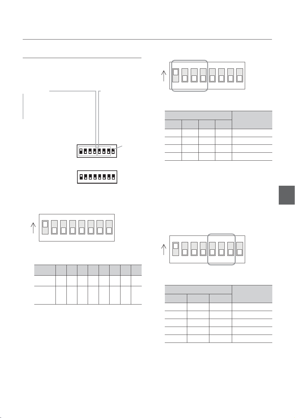
DIP SWITCH SETUP
Installation
❖
Communication Protocol Setup
Before you install the camera, you should set the DIP
switches to confi gure the camera ID, communication
protocol.
w
WWWGaGhGw
WWXGaGwTk
WWYGaGwTw
WWZGaGzhtz|un
Camera ID Setup
❖
ON
ON
pkGzGOX¥Y\\P
iGy
WWWGaGY[WW
WWXGaG[_WW
WWYGaG`]WW
WWZGaGX`YWW
WW[GaGZ_[WW
yzT[_\
{
ON
ON
123456
Select the appropriate Protocol with DIP switch
•
78
combination.
Switch State
Pin1 Pin2 Pin3 Pin4
OFF OFF OFF OFF Auto Protocol
ON OFF OFF OFF PELCO-D
OFF ON OFF OFF PELCO-P
ON ON OFF OFF SAMSUNG
If you set the protocol as Auto Protocol, camera will
•
Protocol
automatically recognize the kind of Protocol.
If you want to control using DVR or system keyboard,
•
their protocol must be identical to camera. Otherwise,
you can not control the camera.
If you changed camera protocol by changing DIP S/W,
•
the change will be effective after you reboot the camera.
Factory default of protocol is “Auto” Protocol
•
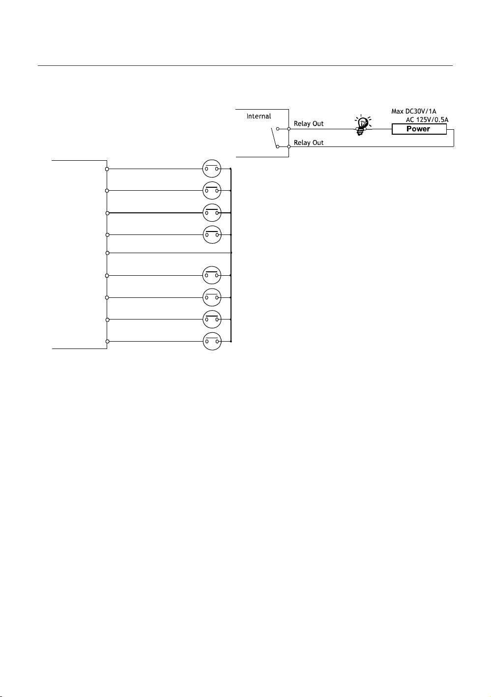
Communication Baud rate Setup
❖
ENG
123456
ID number of camera is set using binary number.
•
78
The example is shown bellow.
Pin 12345678
ID Value 1 2 4 8 16 32 64 128
ex) ID=5
ex) ID=10onoff
The range of ID is 0~255. Factory default of
•
offonon
off
offonoff
off
off
off
off
off
Camera ID is 1.
If you want to control a certain camera, you must
•
match the camera ID with Cam ID setting of DVR
or Controller.
off
off
ON
ON
123456
Select the appropriate Baud rate with DIP switch
•
78
combination.
Switch State
Pin5 Pin6 Pin7
OFF OFF OFF 2400 BPS
ON OFF OFF 4800 BPS
OFF ON OFF 9600 BPS
ON ON OFF 19200 BPS
OFF OFF ON 38400 BPS
•
Factory default of Baud rate is “9600 BPS”
Protocol
English – 9
Page 10

Installation
A
RS-485 Termination Resistor
❖
ON
ON
123456
Pin 8 is used for ON/OFF of RS-485 Termination.
•
78
Normally, it must be OFF state. Especially when
you have trouble with long Daisy chain style
connection, turn ON this termination switch of last
camera.
Pin 8 RS-485 Termination Resistor (On/Off)
–
INSTALLATION USING MOUNT
BRACKET
① Using the paper template, mark the holes on the
wall.
③ After locating the wall mount bracket on the
anchor bolts properly. Tighten the nuts for
anchor bolts
④ Connect cables to terminal blocks and BNC in
the inner box of junction box. See the cabling in
② After drilling the holes, fi x the four anchor bolts
into the holes.
10 – 36x SMART DOME CAMERA
the next section.
Protocol,
Address DIP
RS-485
Connector to the dome camera
POWER
BNC
VIDEO
LARM
Page 11

Installation
⑤ After hooking the safety cable on the hole of
pipe [1], attach the upper housing to wall mount
bracket by turning it at least seven turns [2]. To
fi x the upper body orientation, turn the handle of
double nuts to clockwise tightly [3].
Open the dome cover to install the PTZ camera
⑥
mechanism. Care must be taken dome cover is
hung by internal safety cable properly. Plug fan/
heater cables into the connectors in the housing.
⑦ Plug the connector of cable from junction box
into properly. After checking the orientation
of one touch connector in the upper housing,
press the PTZ mechanism into hook in the
upper housing.
ENG
⑧ To lock the PTZ mechanism to the upper
housing, press the two black handles till it
sounds snap.
G
English – 11
Page 12

Installation
⑨ Close the dome cover. Care must be taken to
locate dome cover by matching the “Arrow”
mark.
ٻ
ٻ
ٻ
ٻ
ٻ
ٻ
⑩ Tighten four screws on the dome cover in
sequence as shown in the picture bellow.
ٻ
ٻ
ٻ
1
To maintain the best sealing, the torque of each
screw must be in the range between 0.5 ~ 1.0 N·m
(0.37 ~ 0.73 lbf·ft).
ٻ
ٻ
ٻ
3
4
2
12 – 36x SMART DOME CAMERA
Page 13

CABLING
DVR/ Keyboard
DVR/ Keyboard
DVR/ Keyboard
RS-485
RS-485
RS-485
D+ D- D+
D+ D- D
D+ D-D- D
Connector to the dome camera
Connector to the dome camera
BNC
BNC
VIDEO
VIDEO
Monitor
Monitor
Installation
ALARM OU TPUT
ALARM OU TPUT
ALARM OU TPUT
12 34
12 34
12 34
ALARM IN PUT
ALARM IN PUT
ALARM IN PUT
G1234 5678
G1234 5678
G1234 5678
POWER
POWER
POWER
NC.
NC.
NC.
ENG
Power Connection
❖
Please, check the voltage and current capacity of rated power carefully.
•
Rated Power Input Voltage Range Current Consumption
AC 24V AC 19V ~29V 2.5 A
RS-485 Communication
❖
For PTZ control, connect this line to keyboard and DVR. To control multiple cameras at the same time, RS-485
•
communication lines of them is connected in parallel as shown below.
English – 13
Page 14
Installation
Video Connection
❖
Connect with BNC coaxial cable.
•
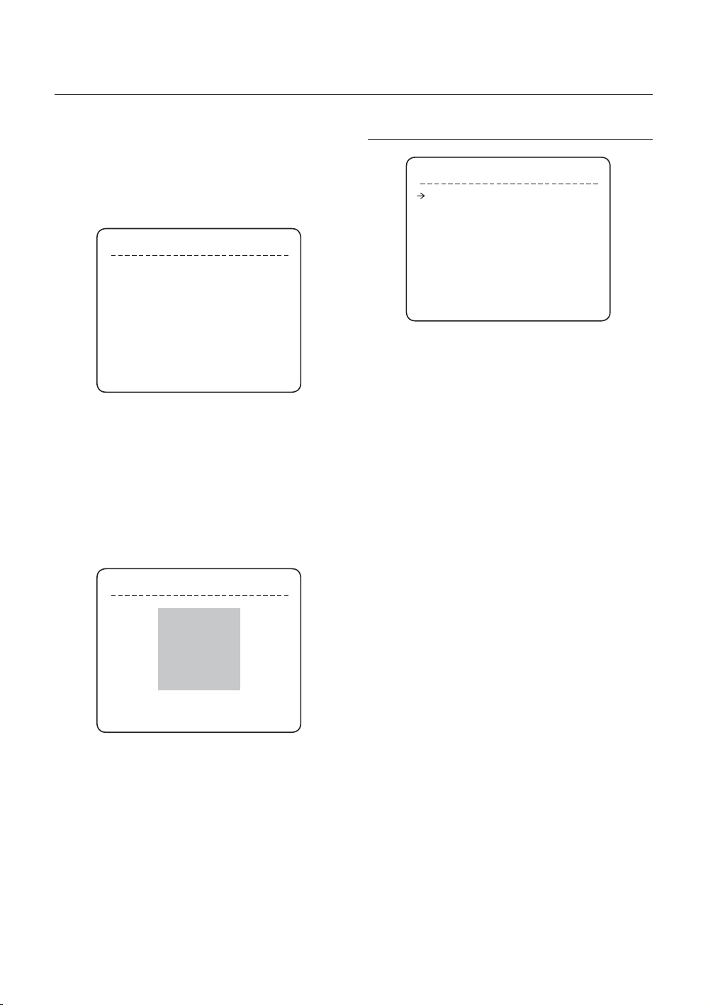
Alarm Output
•
Alarm Input Connection
❖
Sensor Input
•
IN 1
INTERNAL
IN 2
IN 3
IN 4
GND
IN 5
IN 6
IN 7
IN 8
a It is noted that short circuit between GND and
Input pin means alarm activation.
There are 4 Alarm Outputs and all of them are
Relay contact type. Therefore, you do not have
to care about polarity, AC/DC, and isolations
between channels. Care must be taken for the
power capacity of relay contact written above.
If you want to use Alarm Input, the types of sensor
must be selected in OSD menu. The sensor types
are Normal Open and Normal Close If sensor type
is not selected properly, the alarm can be activated
reversely.
14 – 36x SMART DOME CAMERA
Page 15

Operation
CHECK POINTS BEFORE
OPERATION
Before power is applied, please check the cables
•
carefully.
The camera ID of the controller must be identical to
•
that of the camera to be controlled. The camera ID
can be checked in the System Information of OSD
Menu.
If your controller supports multi-protocols, the
•
protocol must be changed to match to that of the
camera.
If you changed camera protocol by changing DIP
•
switch, the change will be effective after you reboot
the camera.
Since the operation method can be different for
•
each controller available, refer to the manual for your
controller if camera can not be controlled properly.
PRESET AND PATTERN
FUNCTION PRE-CHECK
•
Check how to operate Preset, Scan, Auto Pan and
Pattern function with controller or DVR in advance to
operate camera function using them. (refer to your
System keyboard Manual)
•
If controller or DVR has no pattern button or function,
use shortcut keys with preset numbers. For more
information, refer to “Reserved Preset” in this
manual.
AUTO CALIBRATION
•
If the camera is continuously subjected to very high
temperature (over 50°C or 122°F) environment for a
long time, it is possible for the camera to lose focus.
As a result, you will get blurry image. In this case, it is
recommended to turn on “AUTO CALIBRATION” by
running Preset 165.
•
If you execute AUTO CALIBRATION, camera will
calibrate its focus at every 6 hours. To turn off this
function, please, run Preset 166.
STARTING OSD MENU
Function
•
Using the OSD menu, Preset, Pattern, Auto Pan,
Scan and Alarm Input function can be confi gured for
each application.
Enter Menu
•
<Go Preset> [95]
RESERVED PRESET
Description
•
Some Preset numbers are reserved to special
functions.
Function
•
<Go Preset> [95] : Enters into OSD menu
<Go Preset> [131~134] : Runs Pattern Function 1~4
<Go Preset> [141~148] : Runs Auto Pan Function 1~8
<Go Preset> [151~158] : Runs Scan Function 1~8
<Go Preset> [161~164] : Sets Relay 1~4 Output to OFF
<Set Preset> [161~164] : Sets Relay 1~4 Output to ON
<Go Preset> [170] : Sets Camera BLC Mode to OFF
<Go Preset> [171] : Sets Camera BLC Mode to HIGH
<Go Preset> [174] : Sets Camera Focus Mode to AUTO
<Go Preset> [175] : Sets Camera Focus Mode to Manual
<Go Preset> [176] : Sets Camera Focus Mode to SEMI-
AUTO
<Go Preset> [177] : Sets Day & Night Mode to AUTO1
<Go Preset> [178] : Sets Day & Night Mode to NIGHT
<Go Preset> [179] : Sets Day & Night Mode to DAY
<Go Preset> [190] : Sets OSD Display Mode to AUTO
(Except Privacy Mask)
<Go Preset> [191] : Sets OSD Display Mode to OFF
(Except Privacy Mask)
<Go Preset> [192] : Setting OSD Display Mode to ON
(Except Privacy Mask)
<Go Preset> [193] : Sets all Privacy Mask Display to OFF
<Go Preset> [194] : Sets all Privacy Mask Display to ON
<Go Preset> [167] : Zoom Proportional Jog ON
<Set Preset>[167] : Zoom Proportional Jog OFF
<Go Preset>[200] : Digital Zoom ON
<Go Preset>[201] : Digital Zoom OFF
ENG
English – 15
Page 16

Operation
PRESET
Function
•
Max. 127 positions can be stored as Preset position.
The Preset number can be assigned from 1 to 128,
but 95 is reserved for starting OSD menu.
Camera characteristics (i.e. White Balance, Auto
Exposure) can be set up independently for each preset
and they are adjusted by using OSD menu. Four relay
outputs can be reacted in conjunction with one Preset.
Set Preset
•
<Set Preset> [1~128]
Run Preset
•
<Go Preset> [1~128]
Delete Preset
•
To delete Preset, use OSD menu.
AUTO PAN
Function
•
By using Auto Pan function, you can make camera
to move between 2 Preset positions repeatedly.
When Auto Pan function runs, camera moves
from the preset assigned as the 1st point to the
preset assigned as the 2nd point in CW(Clockwise)
direction. Then camera moves from the preset
assigned as the 2nd point to the preset assigned as
the 1st point in CCW(Counterclockwise) direction.
In case that the preset assigned as the 1st point
is same as the preset assigned as the 2nd point,
camera turns on its axis by 360° in CW(Clockwise)
direction and then it turns on its axis by 360° in
CCW(Counterclockwise) direction.
Speed can be set up from 1°/sec to 180°/sec.
Set Auto Pan
•
To set Auto Pan, use OSD menu.
•
Run Auto Pan
Method1) <Run Auto Pan> [Auto Pan NO.] [Enter]
Method2) <Go Preset> [Auto Pan NO.+140]
ex) Run Auto Pan 2 : <Go Preset> [142]
•
Delete Auto Pan
To delete Auto Pan, use OSD menu.
PATTERN
Function
•
Pattern Function is that a camera memorizes the path
(mostly curve path) by joystick of controller for assigned
time and revives the path exactly as it memorized.
4 Patterns are available and Maximum 1000
communication commands can be stored in a pattern.
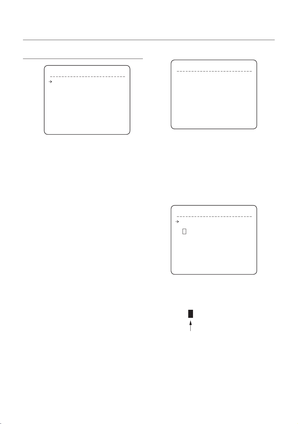
Set Pattern
•
Pattern can be created by one of following two
methods.
Method 1) <Set Pattern> [Pattern NO.]
Pattern editing screen is displayed as bellow.
–
EDIT PATTERN 1
[NEAR:SAVE / FAR:DELETE]
Movement by Joystick and preset movement
–
can be memorized in a pattern.
The rest memory size is displayed in progress
–
bar.
To save the recording, press NEAR key and to
–
cancel, press FAR key.
Method 2) OSD Using OSD Menu: See the section
“How to use OSD Menu”.
Run Pattern
•
Method 1) <Run Pattern> [Pattern NO.] [Enter]
ex) Run Pattern 2 : <Run Pattern> [2] [Enter]
Method 2) <Go Preset> [Pattern NO.+130]
ex) Run Pattern 2: <Go Preset> [132]
Delete Pattern
•
Use OSD menu to delete a Pattern.
a When the PATTERN is saved/executed, the PAN/
TILT is operated with AUTO FLIP OFF.
0/0/X1/N
16 – 36x SMART DOME CAMERA
Page 17

Operation
SCAN
Function
•
The Scan function allows running sequence of
Presets, Pattern and/or Auto Pans. Max 8 Scan
can be stored. Each Scan can have max 20 action
entities which can be preset, pattern or Auto Pan.
Preset speed can be set up and the repeat number
of Pattern & Auto Pan can be set up in Scan setup.
Dwell time between actions can be set up also.
Dwell Time
Preset 1
Set Scan
•
Use OSD Menu to create a Scan.
Run Scan
•
Method1) <Run Scan> [Scan NO] [Enter]
Method2) <Go Preset> [Scan NO.+150]
ex) Run Scan 7 : <Go Preset> [157]
Delete Scan
•
Use OSD Menu to delete.
Pattern 1
Max 20 Entities
Scan 1
SCHEDULE
Function
•
The Schedule function allows running an appropriate
function like Preset, Auto Pan, Scan, Pattern, Home
move at designated day and time. For example, if
you setup a rule Tuesday at 9:00AM and Preset 1
(say Main Gate), the camera will move to main gate
every Tuesday at 9:00AM. If you choose Weekday,
camera will move to Main gate everyday except
weekend.
It is noted that due to the real time clock, the time
data will be kept regardless of blackout. The initial
time and day setup is essential to proper Schedule
function.
Set Schedule
•
Use OSD Menu to create a Schedule
Run Schedule
•
Use OSD Menu of Schedule Master Enable
•
Delete Schedule
Use OSD Menu to delete.
OTHER FUNCTIONS
Preset Lock
•
This function is made to protect preset data from
unauthorized overwriting. If Preset Lock is ON,
Preset save command using Hot Key is disabled
while Preset save using OSD Menu is acceptable.
Power Up Action
•
This function enables to resume the last action
executed before power down. Most of actions such as
Preset, Pattern, Auto Pan and Scan are available for this
function but Jog actions are not available to resume.
if there are no setup for those functions like
Preset, Pattern, Auto Pan and Scan, Camera will
automatically move to Home position after rebooting.
If Power Up Action is set to be ON, camera will
continue the function which is executed lastly after
rebooting.
Auto Flip
•
In case that tilt angle arrives at the top of tilt orbit
(90°), zoom module camera keep moving to opposite
tilt direction (180°) to keep tracing targets. As soon
as zoom module camera passes through the top
of tilt direction(90°), images should be reversed
automatically and F appears in screen. If this
function is set to OFF, tilt movement range is 0 ~ 90°.
Parking Action
•
This function enables to locate the camera to specifi c
position automatically if operator doesn’t operate the
controller for a while. The Park Time can be defi ned
as an interval from 5 seconds to 4 hours.
Alarm Input
•
8 Alarm Inputs are used. If an external sensor
is activated, camera can be set to move to
corresponding preset position. It is noted that the
latest alarm input is effective if multiple sensors are
activated.
Alarm Output
•
There are 4 Ch. of Alarm Outputs and all of them
can be assigned to a certain Preset number. For
example, if you assign Preset 5 to AO2, calling
Preset 5 result in turning On of AO2.
Privacy Zone Mask
•
To protect privacy, MAX. 8 Privacy Masks can be
created on the arbitrary position to hide objects such
as windows, shops or private house. With Spherical
Coordinates system, powerful Privacy Zone Mask
function is possible.
GENERAL/SPECIAL Image Setup
•
WB (White Balance) and AE (Auto Exposure) can
ENG
English – 17
Page 18

Operation
be set up independently for each preset. There
are 2 modes, “General” mode & “Special” mode.
The General mode means that WB or AE can be
set up totally and simultaneously for all presets in
“ZOOM CAMERA SETUP” menu. The Special mode
means that WB or AE can be set up independently
or separately for each preset in each preset setup
menu. Each Special WB/AE value should activate
correspondingly when camera arrives at each preset
location.
During jog operation, General WB/AE value should
be applied. All Special WB/AE value will not be
changed although General WB/AE value change.
•
Semi Auto Focus
This mode exchanges focus mode automatically
between Manual Focus mode and Auto Focus mode
by operation. Manual Focus mode activates in preset
operation and Auto Focus mode activates during jog
operation. With Manual mode at presets, Focus data
is memorized in each preset in advance and camera
calls focus data in correspondence with presets as
soon as camera arrives at a preset. It should shorten
time to get focuses.
Focus mode changes to Auto Focus mode
automatically when jog operation starts.
“PRESET ×××”
“PATTERN ×”
“AUP×/PRESET ×××”
“UNDEFINED”
Preset Label
•
The Label stored for specifi c Preset.
Alarm Information
•
This information shows current state of Alarm Input.
The “I” means Input and “O” is output. If an Input is
ON state it will show the number of input. If an Input
is OFF state, ‘-’ will be displayed. In the same way
“O :1” means output 1 is ON “O :-“ is OFF.
Ex) When Point 2 of inputs are ON, and Output 1 is
On, OSD will show as below
•
Image Flip
Shows that images are currently reversed by Auto
Flip Function.
•
Date/Time
Displays Current Date and Time.
OSD DISPLAY OF MAIN SCREEN
Action Title
Alarm Information
Image Flip
Camera ID
LABEL12345
PRESET1
P/T/Z Information
Preset Lable 1
Date/Time
Camera ID
P/T/Z Information
•
Current Pan/Tilt angle in degree, zoom magnifi cation
and a compass direction.
Camera ID
•
Current Camera ID(Address).
•
Action Title
Followings are possible Action Titles and their meaning.
“SET PRESET ×××”
18 – 36x SMART DOME CAMERA
GENERAL RULES OF KEY
OPERATION FOR MENU
•
The menu items surrounded with < > always has its
sub menu.
For all menu level, to go into sub menu, press NEAR
•
or ENTER key.
To go to up-one-level menu, press FAR key.
•
To move from items to item in the menu, use joystick
•
in the Up/Down or Left/Right.
To change a value of an item, use Up/Down of the
•
joystick in the controller.
Press NEAR or ENTER key to save values and
•
Press FAR key to cancel values.
Page 19

How to use OSD Menu
MAIN MENU
ROOT MENU
<SYSTEM INFORMATION>
<DISPLAY SETUP>
<MOTION SETUP>
<FUNCTION SETUP>
<CAMERA SETUP>
<SYSTEM SETUP>
<SYSTEM INITIALIZE>
EXIT
System Information
•
Shows info and current confi guration.
Display Setup
•
Enable/Disable of OSD display on Main Screen.
Motion Setup
•
Setup for motion related settings
Function Setup
•
Setup for various functions such as Preset, Auto
Pan, Pattern, Scan and Schedule.
Camera Setup
•
Confi gure Camera related functions and data
System Setup
•
Confi gure for Basic system setup.
System Initialize
•
Initializes system confi guration and sets all data to
factory default confi guration.
SYSTEM INFORMATION
Baud rate Shows current Baud rate of PTZ
•
control.
Address Shows current Camera ID for PTZ
•
control.
DISPLAY SETUP
DISPLAY SETUP
CAMERA ID ON
PTZ INFORMATION AUTO
ACTION TITLE AUTO
RESET LABEL AUTO
ALARM I/O AUTO
DATE/TIME ON
<PRIVACY ZONE>
BACK
EXIT
This menu defi nes Enable/Disable of OSD display on
Main Screen. If an item is set to be AUTO, the item is
displayed only when the value of it is changed.
Camera ID [ON/OFF]
•
PTZ Information [ON/OFF/AUTO]
•
Action Title [ON/OFF/AUTO]
•
Preset Label [ON/OFF/AUTO]
•
Alarm I/O [ON/OFF/AUTO]
•
Date/Time [ON/OFF]
•
<Privacy Zone> Start Privacy Zone Mask
•
setup Menu.
PRIVACY ZONE MASK SETUP
Select area in image to mask.
Mask No. [1~8]
•
ENG
SYSTEM INFORMATION
FIRMWARE VER 1.00S36
COLOR SYSTEM NTSC
PROTOCOL SAMSUNG
BAUD RATE 9600
ADDRESS 255
BACK
EXIT
Firmware Ver.
•
Shows current fi rmware version of camera.
Color System
•
Shows current analog video system of the camera.
•
Protocol
Shows current Protocol for PTZ control
PRIVACY ZONE
MASK NO. 1
UNDEFINED
DISPLAY OFF
CLEAR MASK CANCEL
<EDIT MASK>
BACK
EXIT
Select Mask number. If the selected mask has
already data, camera moves as it was set.
Otherwise, “UNDEFINED” will be displayed under
“Mask NO”.
English – 19
Page 20
How to use OSD Menu
Display [ON/OFF]
•
Sets if camera makes mask shows or not on images.
Clear Mask [CANCEL/OK]
•
Deletes data in the selected mask NO.
Privacy Zone Area Setup
❖
EDIT MASK 1
MOVE TO TARGET POSITION
[NEAR:SELECT/FAR:CANCEL]
0/0/x1/N
Move camera to area to mask. Then the menu to
adjust mask size will be displayed.
If the tilt angle is located in the range between 90°
to 90°, you can not set up privacy zone mask.
If tilt angle over 90° (image fl ipped region) is
designated, camera will automatically move to
identical poison by changing tilt angle less than 90°
and moving pan angle 180 relatively.
Privacy Zone Size Adjustment
❖
EDIT MASK 1
[ZOOM : COLOR CHANGE]
[◄►:ADJUST MASK WIDTH]
[▲▼:ADJUST MASK HEIGHT]
[NEAR:SAVE / FAR:CANCEL]
Adjust mask size. Use joystick or arrow buttons to
adjust mask size.
◄► (Left/Right) Adjusts mask width.
•
▲▼ (Up/Down) Adjusts mask height.
•
•
Zoom In/Out Change Color of mask.
To hide a certain zone completely regardless of high
speed PT motions, it is recommended that the size of
mask must be 20% bigger than original target size.
It is noted that during PAN/TILT control like jog
action, the object behind the privacy mask can be
disclosed in a short period of time.
MOTION SETUP
MOTION SETUP
PRESET LOCK OFF
PWR UP ACTION ON
AUTO FLIP ON
JOG MAX SPEED 140/SEC
JOG DIRECTION INVERSE
FRZ IN PRESET OFF
<PARKING ACTION SETUP>
<ALARM INPUT SETUP>
BACK
EXIT
Setup the general functions of Pan/Tilt motions.
Preset Lock [ON/OFF]
•
If Preset Lock is set to ON, it is impossible to set up
and delete Preset, APAN, Pattern and SCAN. It is
possible only to run those functions. To set up and
delete those functions, enter into OSD menu.
Power Up Action [ON/OFF]
•
Refer to “Other Functions”(page 17) section.
Auto Flip [ON/OFF]
•
Refer to “Other Functions”(page 17) section.
Jog Max Speed [2°/sec ~200°/sec]
•
Sets maximum jog speed. Jog speed is inversely
proportional to ratio of zoom. As zoom magnifi cation
goes up, pan/tilt speed goes down.
Jog Direction [INVERSE/NORMAL]
•
If you set this to ‘Normal’, the view in the screen is
moving same direction with jog tilting. If ‘Inverse’ is
selected, the view in the screen is moving reversely.
Freeze in Preset [ON/OFF]
•
At start point of preset movement, camera starts
freezing the image of start point. Camera keeps
displaying the image of start point during preset
movement and does not display the images which
camera gets during preset movement. As soon as
camera stops at preset end point, camera starts
displaying live images which it gets at preset end
point.
20 – 36x SMART DOME CAMERA
Page 21

Parking Action Setup
❖
How to use OSD Menu
FUNCTION SETUP
PARKING ACTION SETUP
PARK ENABLE OFF
WATT TIME 00:10:00
PARK ACTION HOME
BACK
EXIT
If Park Enable is set to ON, camera runs assigned
function automatically if there is no PTZ command
during assigned “Wait Time”.
Park Enable [ON/OFF]
•
Wait Time [5 sec ~ 4 hour]
•
The time is displayed with “hh:mm:ss” format and
you can change this by 1 sec unit.
Park Action
•
[HOME/PRESET/PATTERN/AUTOPAN/SCAN]
Ex) If HOME is selected for Park Action, camera
will move to home position when there is no PTZ
command during assigned “Wait Time.”
Alarm Input Setup
❖
ALARM INPUT SETUP
ALARM1 N.0 PRESET1
ALARM2 N.0 NOT USED
ALARM3 N.0 NOT USED
ALARM4 N.0 NOT USED
ALARM5 N.0 PRESET1
ALARM6 N.0 NOT USED
ALARM7 N.0 NOT USED
ALARM8 N.0 NOT USED
BACK
EXIT
FUNCTION SETUP
<PRESET SETUP>
<AUTO PAN SETUP>
<PATTERN SETUP>
<SCAN SETUP>
<SCHEDULE SETUP>
BACK
EXIT
Confi gure 5 Special Functions with this menu
Preset Setup
•
127 Presets from the number 1 to 128 can be
assigned excluding preset 95 reserved for Menu.
Auto Pan Setup
•
Up to 8 Auto Pans are available, which makes
camera to move slowly between two preset points.
Pattern Setup
•
Up to 4 patterns can be stored in the dome.
In this function, path data created by manual move
of Joystick are recorded and you can playback the
identical path automatically whenever required.
Scan Setup
•
Up to 8 Scans can be defi ned.
In a Scan, max 20 entities are assigned from any
combinations of Preset/Auto Pan/Pattern. If you run
a Scan, camera will execute each entry sequentially.
•
Schedule Setup
7 rules of Schedule can be assigned by day and
time. Appropriate actions (such as Home, Preset,
Auto Pan, Pattern and Scan) can be defi ned for
each rule. Also, it is possible to use Weekday and
Weekend in a rule to make it simple.
ENG
Match the Alarm sensor input to one of Preset
positions. If an external sensor is activated, camera
will move to corresponding preset position when this
item is predefi ned.
•
Alarm Type
[Normal OPEN(N.O) / Normal CLOSE(N.C)]
Sets sensor input type.
•
Alarm Action
[NOT USED/HOME/PRESET 1~128/APAN 1~8,
PATTERN1~4, SCAN 1~4]
For each Alarm input, you can assign counteraction
functions (Preset, Auto Pan, Pattern, Scan).
English – 21
Page 22
How to use OSD Menu
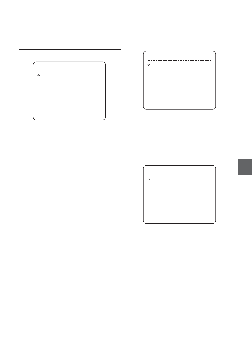
Edit Preset Scene
PRESET SETUP
❖
PRESET SETUP
PRESET NO. 1
<EDIT SCENE>
<LABEL> WINDOWS
CLR PRESET CANCEL
CAM ADJUST GENERAL
ALARM OUT ----
BACK
EXIT
Preset Number [1~128]
•
If a selected preset is already defi ned, camera moves
to pre-defi ned position and preset characteristics
such as Label and Relay Outputs show on monitor.
If a selected preset is not defi ned, “UNDEFINED”
shows on monitor.
•
Edit Scene
Redefi ne current Preset scene position (i.e. PTZ).
Label
•
Edits Label to show on monitor when preset runs.
MAX. 10 alphabets are allowed.
CLR Preset [CANCEL/OK]
•
Delete current Preset data
CAM Adjust [GENERAL/SPECIAL]
•
WB(White Balance) and AE(Auto Exposure) can
be set up independently for each preset. There are
2 modes, “General” mode & “Special” mode. The
General mode means that WB or AE can be set up
totally and simultaneously for all presets in “CAMERA
SETUP” menu.
The Special mode means that WB or AE can be
set up independently or separately for each preset
in each preset setup menu. Each Special WB/AE
value should activate correspondingly when camera
arrives at each preset location. During jog operation,
General WB/AE value should be applied.
All Special WB/AE value should not change although
General WB/AE value changes. If “Special’’ is
selected, Menu to set WB/AE shows on monitor.
Alarm out
•
State of four alarm outputs can be freely controlled in
conjunction with Preset run. The character “-“ means
OFF state and the number representing each bit
means ON.
Ex) If it is set to be -23-, Output relay 2, 3 will be ON
and 1, 4 will be OFF, when you run this Preset.
EDIT SCENE - PRESET 1
MOVE TO TARGET POSITION
[NEAR:SAVE / FAR:CANCEL]
0/0/x1/N
① Using joystick, move camera to desired position.
② By pressing NEAR or ENTER key, save current
PTZ data.
③ Press FAR key to cancel.
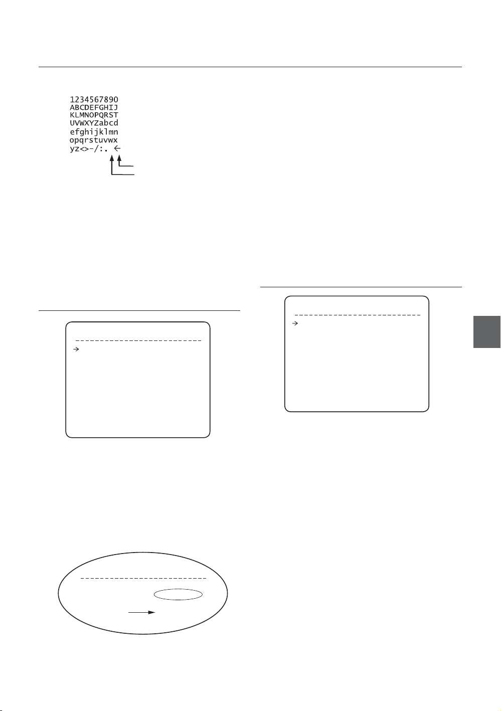
Edit Preset Label
❖
LABEL - PRESET 1
[█ ]
--------- 1234567890 OK
ABCDEFGHIJ CANCEL
KLMNOPQRST
UVWXYZabcd
efghijklmn
opqrstuvwx
yz<>-/:.
①
Edits label to show on monitor when camera
arrives at presets. In Edit Label menu, a reverse
rectangular is cursor. As soon as fi nishing
selecting alphabet, cursor moves to the next digit.
[ ]
Current Cursor Position
② Using Left/Right/Up/Down of joystick, move to
an appropriate character from the Character set.
To choose that character, press the NEAR or
ENTER key.
22 – 36x SMART DOME CAMERA
Page 23
How to use OSD Menu
Back Space Char.
Space Char.
If you want to use blank, choose Space
character (“ ”). If you want to delete a character
before, use back space character (“”).
③ If you complete the Label editing, move cursor
to “OK” and press NEAR or ENTER key to save
completed label. To abort current change, move
cursor to “Cancel” and press NEAR or ENTER key.
When Auto Pan function runs, camera moves
from the preset assigned as the 1st point to the
preset assigned as the 2nd point in CW(Clockwise)
direction. Then camera moves from the preset
assigned as the 2nd point to the preset assigned as
the 1st point in CCW(Counterclockwise) direction.
In case that the preset assigned as the 1st point
is same as the preset assigned as the 2nd point,
camera turns on its axis by 360° in CW direction and
then it turns on its axis by 360° in CCW direction.
APAN(AUTO PAN) Speed [1°/sec ~180°/sec]
•
Sets Auto Pan speed from 1°/sec to 180°/sec.
Clear APAN(AUTO PAN) [CANCEL/OK]
•
Deletes current Auto Pan data.
PATTERN SETUP
AUTO PAN SETUP
AUTO PAN SETUP
APAN NO. 1
1ST POS. NOT USED
2ND POS. NOT USED
APAN SPEED
CLEAR APAN CANCEL
BACK
EXIT
Auto Pan Number [1~8]
•
Selects Auto Pan number to edit. If a selected Auto
Pan has not defi ned, “NOT USED” is displayed in 1st
Position and 2nd Position
•
1st Position / 2nd Position [PRESET 1~128]
Set up the 2 position for Auto Pan function. If a
selected preset is not defi ned, “UNDEFINED” will be
displayed as shown below.
AUTO PAN SETUP
APAN NO. 1
1ST POS. PRESET5
2ND POS. PRESET8
UNDEFINED
30/SEC
PATTERN SETUP
PATTERN NO. 1
UNDEFINED
CLEAR PATTERN CANCEL
<EDIT PATTERN>
BACK
EXIT
Pattern Number [1~4 ]
•
Selects Pattern number to edit.
If a selected pattern number is not defi ned,
“UNDEFINED” will be displayed under selected
pattern number.
Clear Pattern [CANCEL/OK]
•
Deletes data in current pattern
Edit Pattern
•
Starts editing pattern.
ENG
English – 23
Page 24

How to use OSD Menu
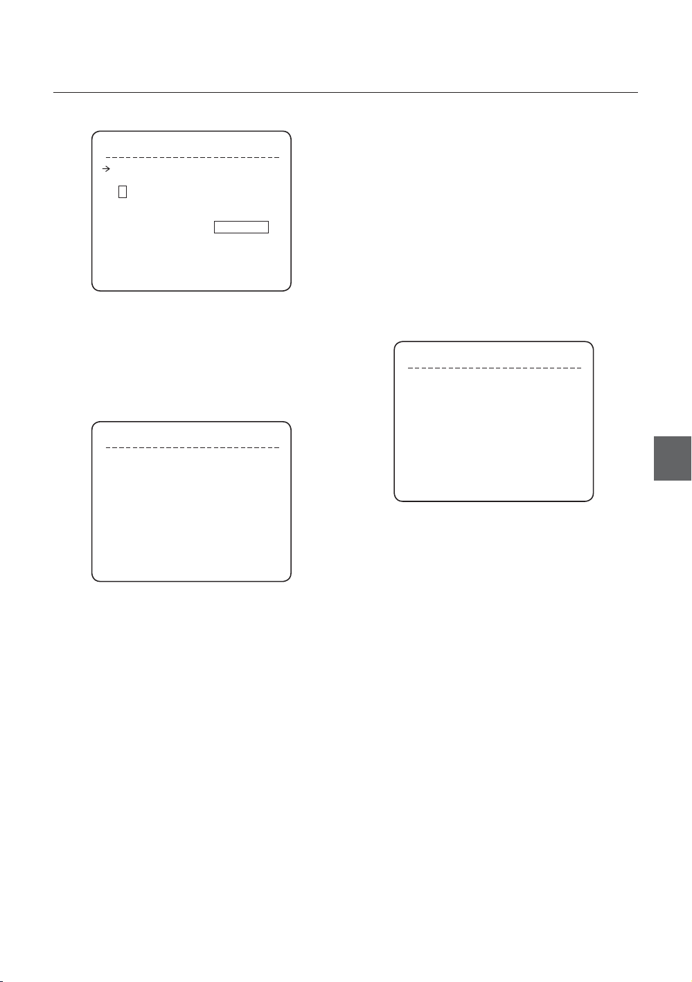
❖
Edit Pattern
SCAN SETUP
① By using Joystick, move to start position with
appropriate zoom. To start pattern recording,
press NEAR or ENTER key. To exit this menu,
press FAR key.
EDIT PATTERN 1
MOVE TO START POSITION
[NEAR:START/ FAR:CANCEL]
0/0/x1/N
② Move camera with joystick of controller or run
preset function to memorize the path (mostly
curve path) in a selected pattern. The total
memory size and the rest memory size is
displayed in the form of bar. Maximum 1,000
communication commands can be stored in a
pattern.
EDIT PATTERN 1
[NEAR:SAVE / FAR:DELETE]
0/0/X1/N
SCAN SETUP
SCAN NO. 1
UNDEFINED
CLEAR SCAN CANCEL
<EDIT SCAN>
BACK
EXIT
Scan Number [1~8]
•
Selects Scan number to edit.
If a selected Scan number is not defi ned,
“UNDEFINED” will be displayed under selected Scan
number.
Clear Scan [CANCEL/OK]
•
Deletes data in current Scan
Edit Scan Starts editing Scan.
•
Edit Scan
❖
① Press NEAR or ENTER key in “NO” list to start
Scan setup.
EDIT SCAN 1
NO. ACTION NO. DWELL OPT
1 NONE
2 NONE
3 NONE
4 NONE
5 NONE
SAVE
CANCEL [NEAR:EDIT]
③ To save data and exit, press NEAR or ENTER
key. To cancel recording and delete record
data, press FAR key.
24 – 36x SMART DOME CAMERA
② Note that MAX. 20 Functions are allowed in a
Scan. Move cursor up/down and press NEAR
or ENTER key to set up.
EDIT SCAN 1
NO. ACTION NO. DWELL OPT
1 NONE
2 NONE
3 NONE
4 NONE
5 NONE
SAVE [NEAR:EDIT ACT]
CANCEL [FAR :EDIT END]
Page 25

How to use OSD Menu
③ Set up Action, Dwell time and Option. Note
that selected item is displayed in reverse. Move
cursor Left/Right to select items and move
cursor Up/Down to change each value.
EDIT SCAN 1
NO. ACTION NO. DWELL OPT
1 NONE
2 NONE
3 NONE
4 NONE
5 NONE
SAVE [◄►:MOVE CURSOR]
CANCEL [▲▼:CHANGE VAL.]
•
Action NO.
[NONE/PRESET/AUTO PAN/PATTERN]
•
DWELL [1 second ~ 4 minutes]
Sets Dwell Time between functions
•
OPT
Option. It represents preset speed (2~360)
when preset is selected. It should be the
number of repetition (1~255) when Pattern or
Auto Pan is selected for Action
④ Set up items such as Action, NO., Dwell and
OPT.
EDIT SCAN 1
NO. ACTION NO. DWELL OPT
1 PRESET 1 00:03 360
2 NONE
3 NONE
4 NONE
5 NONE
SAVE [◄►:MOVE CURSOR]
CANCEL [▲▼:CHANGE VAL.]
⑤ After fi nishing setting up an Action, press NEAR
or ENTER key to one-upper-level menu (Step
②). Move cursor Up/Down to select Action
number and repeat Step ② ~ Step ④ to edit
selected Scan.
EDIT SCAN 1
NO. ACTION NO. DWELL OPT
1 PRESET 1 00:03 360
2 NONE
3 NONE
4 NONE
5 NONE
SAVE [NEAR:EDIT ACT]
CANCEL [FAR :EDIT END]
⑥ After fi nishing setting up all Actions, press FAR
key to exit. Then cursor should be moved to
“SAVE.” Press NEAR or ENTER key to save
data.
EDIT SCAN 1
NO. ACTION NO. DWELL OPT
1 PRESET 1 00:03 360
2 NONE
3 NONE
4 NONE
5 NONE
SAVE
CANCEL
ENG
English – 25
Page 26

How to use OSD Menu
SCHEDULE SETUP
SCHEDULE SETUP
MASTER ENABLE ON
DAY TIME ACT NO ON
1 UNDEFINED
2 UNDEFINED
3 UNDEFINED
4 UNDEFINED
5 UNDEFINED
6 UNDEFINED
7 UNDEFINED
BACK
Master Enable [ON/OFF]
•
Decide whether Schedule function is active or not.
Edit Schedule
❖
① After move the Cursor to the number by using
Up/Down keys, press “NEAR”(Enter) Key to
edit.
SCHEDULE SETUP
MASTER ENABLE ON
DAY TIME ACT NO ON
1 UNDEFINED
2 UNDEFINED
3 UNDEFINED
4 UNDEFINED
5 UNDEFINED
6 UNDEFINED
7 UNDEFINED
BACK
② Each fi eld can be selected by Left/Right keys
and the values in the fi eld are changed using
Up/Down keys.
SCHEDULE SETUP
MASTER ENABLE ON
DAY TIME ACT NO ON
1 MON 00:00 HOM OFF
2 UNDEFINED
3 UNDEFINED
4 UNDEFINED
5 UNDEFINED
6 UNDEFINED
7 UNDEFINED
BACK
The meaning of each value:
DAY Days: MON TUE WED THU
FRI SAT SUN
WKD: Weekday
ALL: All days(Everyday)
TIME 24hour Format
ACT PRS(Preset), AUP(Auto Pan),
PTN(Pattern), SCN(Scan),
HOM(Home)
ON/OFF Decide to make this rule effective or
not
If you fi nish a rule, press NEAR or ENTER key
to select another rule.
Repeat this procedure to fi ll up the schedule in
mind.
③ Example
The second rule means camera will move
–
to Preset 12 position at 7:35 on every
Wednesday.
SCHEDULE SETUP
MASTER ENABLE ON
DAY TIME ACT NO ON
1 MON 01:20 HOM ON
2 WED 07:35 PRS 12 ON
3 THU 11:40 SCN 3 ON
4 SAT 15:17 PTN 1 ON
5 WKD 23:00 HOM ON
6 UNDEFINED
7 UNDEFINED
BACK
* Note: If there are rules confl icts to each other, the
higher number is, the higher priority has.
* Note: If you assign undefi ned function, there will
be no action.
* Hint: Using reserved Preset, you can make
various schedules. For example, PRS179 are
PRS178 are Day and Night mode respectively.
(Refer to Reserved Preset(page 15) List in this
manual.)
26 – 36x SMART DOME CAMERA
Page 27
CAMERA SETUP
How to use OSD Menu
❖
White Balance Setup
Setup the general functions of zoom camera module
ZOOM CAMERA SETUP
FOCUS MODE SEMIAUTO
DIGITAL ZOOM ON
IMAGE FLIP OFF
FLICKERLESS OFF
<WHITE BALANCE SETUP>
<AUTO EXPOSURE SETUP>
BACK
EXIT
Focus Mode [AUTO/MANUAL/SEMIAUTO]
•
Sets camera focus mode.
SEMIAUTO Mode
This mode exchanges focus mode automatically
between Manual Focus mode and Auto Focus
mode. Manual Focus mode activates in preset
operation and Auto Focus mode activates when
jog operation starts.
With Manual mode at presets, Focus data is
memorized in each preset in advance and camera
calls focus data in correspondence with presets as
soon as camera arrives at a preset.
Digital Zoom [ON/OFF]
•
Sets digital zoom function to ON/OFF. If this is set to
OFF, optical zoom function runs but zoom function
stops at the end of optical zoom magnifi cation.
Image Flip [ON/OFF]
•
To display Upside down image.
Flickerless [ON/OFF]
•
Turn on or off the Flickerless function. In this function,
AE mode becomes Shutter Priority mode and shutter
speed value will be fi xed to 1/100 sec.
WB SETUP - GLOBAL
WB MODE AUTO
zRED ADJUST ---
zBLUE ADJUST ---
BACK
EXIT
WB Mode [AUTO/MANUAL]
•
In Manual mode, Red and Blue level can be set up
manually
Red Adjust [0~255]
•
Blue Adjust [0~255]
•
Auto Exposure Setup
❖
AE SETUP
WDR/BLC ALL OFF
DAY/NIGHT AUTO
AE MODE AUTO
IRIS LEVEL ---
GAIN LEVEL ---
SHUTTER SPD ---
BRIGHTNESS ---
BACK
EXIT
WDR/BLC [ ALL OFF / WDR ON / BLC ON ]
•
Select WDR(Wide Dynamic Range) or BLC(Backlight
Compensation) function. All OFF means turning off
both functions.
Day/Night [AUTO/DAY/NIGHT]
•
AUTO exchanges Day / Night
•
AE MODE AUTO / MANUAL / IRIS / SHUTTER
/ BRIGHT
AUTO: Full Auto mode for AE function
MANUAL: In manual mode. IRIS, GAIN, SHUTTER
SPEED can be changed in this mode.
IRIS: Iris priority mode. You can change IRIS while
others are adjusted automatically.
SHUTTER: Shutter priority mode. Shutter speed can
be changed while others are adjusted automatically.
BRIGHT: In this mode, you can assign AE value in
terms of Brightness.
ENG
English – 27
Page 28

How to use OSD Menu
IRIS
•
[Works when AE MODE is MANUAL or IRIS model]
Range: CLOSE/F1.6/F2/F2.4/F2.8/F3.4/F4/F4.8/
F5.6/F6.8/F8/ F9.6/F11/F14/F16/F19/F22/F28.
(18 steps)
•
GAIN
[Works when AE MODE is MANUAL]
Enhances image brightness automatically in case
that luminance level of image signal is too low.
Range: -3/0/2/4/6/8/10/12/14/16/18/20/22/24/26/
28dB (16 steps)
•
Shutter Speed
[Works when AE MODE is MANUAL or SHUTTER
mode]
X64, X32, X16, X8, X4, X2,1/60,1/90,1/100,1/125,1/
180,1/250,1/350,1/500,1/725,1/1000,1/1500,1/
2000,1/4000,1/6000,1/10000
•
Brightness
[Works when AE MODE is BRIGHT]
Adjusts brightness of images. Iris, Shutter Speed and
Gain are adjusted automatically in correspondence
with this value. Range: 0~31 (32 steps)
•
•
It is noted that the range of date setup is limited
DATE/TIME SETUP
DATE 01/JAN/2008(TUE)
TIME 00:00:01(H/M/S)
BACK
EXIT
Time
Time is displayed in HH:MM:SS format.
Date/time Setup
After you press the NEAR or ENTER key, each fi eld
can be selected by Left/Right keys and the values in
the fi eld are changed using Up/Down keys. To save
the updated data, press the NEAR or ENTER key
again
from 01/JAN/2000 to 31/DEC/2037.
SYSTEM SETUP
SYSTEM SETUP
<DATE/TIME SETUP>
<RELAY TYPE>
<PASSWORD>
<SET HOME POSITION>
<SET NORTH DIRECTION>
LANGUAGE ENGLISH
BACK
EXIT
•
System Setup
You can set up DATE/TIME, RELAY TYPE,
PASSWORD, HOME POSITION, NORTH POSITION.
•
Date
Date is displayed in dd/mm/yyyy format. The day is
automatically calculated when you set the date.
RELAY TYPE SETUP
RELAY1 NORMAL OPEN
RELAY2 NORMAL OPEN
RELAY3 NORMAL OPEN
RELAY4 NORMAL CLOSE
BACK
EXIT
•
Relay Type Setup
Contact types of 4 Ch. RELAY OUTPUTS are
defi ned. (NORMAL OPEN / NORMAL CLOSE)
NORMAL OPEN
NORMAL CLOSE
28 – 36x SMART DOME CAMERA
Page 29
How to use OSD Menu
EDIT PASSWORD
[█ ]
--------- 1234567890 OK
ABCDEFGHIJ CANCEL
KLMNOPQRST
UVWXYZabcd DISABLE
efghijklmn
opqrstuvwx
yz<>-/:.
----------
Password Setup
•
You can defi ne 4 characters long password. If this
function is set to ENABLE, it is required to type this
password whenever to enter OSD MENU.
It is noted that MASTER PSSWORD : “4321”
* Set Home Position?
When you replace the camera block or the
orientation of camera is changed due to
maintenance operations, it is very diffi cult to
maintain same pan orientation. Therefore, all
function data depending on pan orientation such
as preset, pattern, scan, auto pan, and privacy
zone mask are not useful any more accordingly.
However, even in this case, you can reuse the
data if you redefi ne Set Home Position on the
previous Home position. It is recommendable
to memorize the target scene of current Home
position.
SET NORTH DIRECTION
SET HOME POSITION
MOVE TO TARGET POSITION
[NEAR:SAVE / FAR:CANCEL]
Set Home Position
•
0/0/x1/N
HOME position means the origin of PAN angle
calculation. The value of PAN angle displayed on the
screen is based on this HOME position.
By using Joystick, move the camera to the desired
position and press ENTER (NEAR/SAVE).
It is noted that Home is not effective to Tilt angle.
If you change the location of Home position, all
horizontal locations of functions such as preset,
pattern, scan, auto pan, and privacy zone mask will
be shifted based on changed Home position.
If there are no setup for those functions like
Preset, Pattern, Auto Pan and Scan, Camera will
automatically move to Home position after rebooting.
If Power Up Action is set to be ON, camera will
continue the function which is executed lastly after
rebooting.
MOVE TO TARGET POSITION
[NEAR:SAVE / FAR:CANCEL]
•
Set North Direction
0/0/x1/N
You can set up North direction.
By using Joystick, move the camera to the desired
NORTH position and press ENTER (NEAR/SAVE).
The direction will be displayed in the screen
[PAN AXIS / TILT AXIS / ZOOM / DD]
DD is direction and will be displayed from:
N/NE/E/SE/S/SW/W/NW
•
Language
You can select a preferred Language of OSD display
from 7 choices.
[ENGLISH/ ESPAÑOL/ FRANÇAIS/ DEUTSCH/
ITALIANO/ РУССКИЙ/ PORTUGUÊS]
After selecting a language, press ENTER(NEAR) key.
ENG
English – 29
Page 30

How to use OSD Menu
SYSTEM INITIALIZE
Motion Confi guration
•
SYSTEM INITIALIZE
CLEAR ALL DATA NO
CLR DISPLAY SET NO
CLR CAMERA SET NO
CLR MOTION SET NO
CLR FUNCTION SET NO
REBOOT CAMERA NO
REBOOT SYSTEM NO
BACK
EXIT
Clear All Data
•
Deletes all confi guration data such as display,
camera, motion setup and so on.
Clear Display Set
•
Initializes Display Confi guration
Clear Camera Set
•
Initializes Camera Confi guration
•
Clear Motion Set
Initializes Motion Confi guration
Clear Function Set
•
Deletes Preset Data, Auto Pan Data, Pattern Data,
Scan Data and Schedule Data
Reboot Camera
•
Reboots Zoom Camera module
Reboot System
•
Reboots Smart Dome Camera
Initial Confi guration Table
❖
Preset Lock OFF
Power Up Action ON
Auto Flip ON
Jog Max Speed 140°/sec
Jog Direction NORMAL
Freeze In Preset OFF
Park Action OFF
Alarm I/O Action OFF
Communication Setup
•
Protocol AUTO
Baud Rate 9600
Camera Confi guration
•
Focus Mode SEMIAUTO
Digital Zoom ON
Image Flip ON
Flickerless OFF
White Balance AUTO
Backlight/BLC ALL OFF
Day/Night AUTO
AE Mode AUTO
Iris Level F4
Gain Level +2dB
Shutter Speed 1/60
Brightness 13
Display Confi guration
•
Camera ID ON
PTZ Information AUTO
Action Title AUTO
Preset Label AUTO
Alarm I/O AUTO
Date/Time ON
Privacy Zone Undefi ned
30 – 36x SMART DOME CAMERA
Function Data
•
Preset 1~128 Undefi ned
Auto Pan 1~8 Undefi ned
Pattern 1~4 Undefi ned
Scan 1~8 Undefi ned
Schedule 1~7 Undefi ned
Page 31

Specifi cations
SPECIFICATIONS
Item Details
Broadcasting
Type
CCD EX-View HAD CCD
Effective Pixels
Horizontal Resolution
S/N Ratio Approx. 50 dB
Zoom x36 Optical Zoom, x12 Digital Zoom
Focal length f=3.4mm(Wide) ~ 122.4mm(Tele), F1.6 ~ F4.5
Camera
Pan/Tilt
General
Specifi cations of this product can be subjected to change without notice.
Min. illumination
Signal Output
Day & Night Auto / Day / Night(ICR)
Focus Auto / Manual / SemiAuto
Iris Auto / Manual
Shutter Speed X64 ~ X2, 1/60 ~ 1/10,000s
AGC Auto/Manual(-3 ~ 28dB)
White Balance Auto / Manual(Red, Blue Gain Adjustable)
WDR, BLC WDR On/Off, BLC On/Off
Flickerless Selectable
Privacy Zone 8 Area
Range
Pan/Tilt Speed
Preset 127 Preset (Label, Camera Image Setting)
Pattern 4 Pattern, 1000 Commands(About 5 Minute)/Pattern
Auto Pan 8 Auto Pan
Scan 8 Scan (20 action entities per Scan)
Other Functions Auto Flip, Auto Parking, Power Up Action etc.
Communication RS-485
Protocol Auto, Pelco-D, Pelco-P, Samsung selectable
Privacy Zone 8 Zone
Alarm Input 8 Input
Alarm Output 4 Relay Output
OSD
Power Input
Power Consumption
Dimension
Weight
Operating Temp. -45°C ~ 50°C(-49°F ~ 122°F)
Lives of Main Parts
Check the rated voltage and current capacity of power supply carefully.
SCC-C7478N : NTSC Standard Color System
SCC-C7478P : PAL Standard Color System
SCC-C7478N : 768(H) × 494(V)
SCC-C7478P : 752(H) × 582(V)
Color : 540 / BW : 570 TV Line
illumination Sens-up Color B/W (S/W)
50 IRE No 1.40 Lux 0.15000 Lux
30 IRE No 0.84 Lux 0.09000 Lux
15 IRE No 0.42 Lux 0.04500 Lux
50 IRE 64 times 0.0219 Lux 0.00230 Lux
30 IRE 64 times 0.0131 Lux 0.00140 Lux
15 IRE 64 times 0.0066 Lux 0.00070 Lux
Composite Video Out : 1.0 Vp-p 75 ohms/BNC
Pan : 360°(Endless)
Tilt : 180°
Preset : 360°/sec
Manual :
0.05 ~ 200°/sec (Inversely Proportional to Zoom)
Auto Pan :1 ~ 180°/sec
Support 7 Languages: [ENGLISH /ESPAÑOL /FRANÇAIS
/DEUTSCH/ITALIANO /РУССКИЙ /PORTUGUÊS]
(With a mount
Wall Mount Type : About 6 kgf (13.2 LB)
Ceiling Mount Type : About 5.8 Kgf (12.8 LB)
Menu / PTZ Information etc
SCC-C7478N : AC 24V ± 10% (60Hz ± 0.3Hz)
SCC-C7478P : AC 24V ± 10% (50Hz ± 0.3Hz)
24W(Heater Off) / 57W(Heater On)
Camera
(Camera only)
Camera
bracket)
Slip Ring : Rotated 10,000,000 times
(Ø × H) : 259 × 265.7 (mm)
: 10.2 × 10.46 (inch)
Wall Mount Type
(W X H X D)
Ceiling Mount Type
(Ø X H)
:259X404.5X 551.7 (mm)
:10.2X15.9X21.7 (inch)
: 259X648.7 (mm)
: 10.2X25.54 (inch)
Appearance
❖
Wall Mount
•
Ceiling Mount
•
ENG
G
English – 31
Page 32

Specifi cations
DIMENSION
•
Wall Mount Bracket
Unit (mm)
Ceiling Mount Bracket
•
32 – 36x SMART DOME CAMERA
Page 33

Correct Disposal of This Product (Waste Electrical & Electronic Equipment)
(Applicable in the European Union and other European countries with separate collection systems)
This marking shown on the product or its literature,indicates that it should not be disposed with other household
wastes at the end of its working life. To prevent possible harm to the environment or human health from uncontrolled
waste disposal,please separate this from other types of wastes and recycle it responsibly to promote the sustainable
reuse of material resources.
Household users should contact either the retailer where they purchased this product,or their local government
office,for details of where and how they can take this item for environmentally safe recycling.
Business users should contact their supplier and check the terms and conditions of the purchase contract.This
product should not be mixed with other commercial wastes for disposal.
Page 34

SCC-C7478
Купольная Камера 36x
Руководство пользователя
удивительные возможности
Благодарим Вас за приобретение данного продукта компании Samsung.
Для получения более полного обслуживания
зарегистрируйте свое устройство по адресу:
www.samsung.com/global/register
RUS
Page 35
Меры предосторожности
ВНИМАНИЕ
ОПАСНОСТЬ ПОРАЖЕНИЯ ЭЛЕКТРИЧЕСКИМ
ТОКОМ! НЕ ОТКРЫВАТЬ!
ВНИМАНИЕ: ВО ИЗБЕЖАНИЕ ПОРАЖЕНИЯ ЭЛЕКТРИЧЕСКИМ ТОКОМ НЕ ОТКРЫВАЙТЕ КРЫШКУ (ИЛИ ЗАДНЮЮ ПАНЕЛЬ)
УСТРОЙСТВА. ВНУТРИ ОТСУТСТВУЮТ ДЕТАЛИ, ОБСЛУЖИВАНИЕ КОТОРЫХ МОЖЕТ ВЫПОЛНЯТЬ ПОЛЬЗОВАТЕЛЬ.
ОБСЛУЖИВАНИЕ ДОЛЖНО ВЫПОЛНЯТЬСЯ КВАЛИФИЦИРОВАННЫМИ СПЕЦИАЛИСТАМИ.
Этот символ обозначает, что внутри устройства имеется опасное напряжение, которое
может привести к поражению электрическим током.
Этот символ указывает, что в документации на изделие имеется важная инструкция по его
использованию или обслуживанию.
ПРЕДУПРЕЖДЕНИЕ
Во избежание повреждений, следствием которых может быть пожар или поражение электрическим
•
током, не допускайте попадания данного изделия под дождь или в условия высокой влажности.
ПРЕДУПРЕЖДЕНИЕ
Пользуйтесь только стандартным блоком питания, который указан в листе спецификаций.
1.
Использование любого другого блока питания может привести к пожару, поражению электрическим
током или к повреждению изделия.
Неправильное подключение блока питания или замена батареи может привести к взрыву, пожару,
2.
поражению электрическим током или к повреждению изделия.
Не подключайте несколько видеокамер к одному блоку питания. Превышение нагрузочной
3.
способности блока питания может привести к его перегреву или к пожару.
Надежно вставьте вилку сетевого шнура в розетку сети переменного тока. Ненадежное подключение
4.
может привести к пожару.
При установке видеокамеры закрепите ее прочно и надежно. Падение видеокамеры может привести
5.
к травме.
Не кладите сверху на видеокамеру токопроводящие предметы (например, отвертки, монеты и другие
6.
металлические предметы) и не ставьте на нее наполненные водой сосуды. Невыполнение этих
требований может привести к пожару, поражению электрическим током или к травмам в результате
падения этих предметов.
Не устанавливайте изделие во влажных, запыленных или покрытых копотью помещениях.
7.
Невыполнение этого требования может привести к пожару или к поражению электрическим током.
Если вы почувствуете необычный запах или обнаружите дым, выходящий из изделия, прекратите
8.
эксплуатацию. В этом случае следует немедленно отсоединить изделие от источника питания и
связаться с сервисным центром. Продолжение эксплуатации изделия в таком состоянии может
привести к пожару или к поражению электрическим током.
9.
При обнаружении неисправности в изделии свяжитесь с ближайшим сервисным центром. Никогда
не разбирайте данное изделие и не вносите изменений в его конструкцию. (Компания SAMSUNG
не несет ответственности за проблемы, возникшие в результате внесения изменений в конструкцию
изделия или попыток самостоятельно выполнить ремонт изделия).
2 – КУПОЛЬНАЯ КАМЕРА 36x
Page 36

Меры предосторожности
10.
При чистке изделия не разбрызгивайте на него воду. Это может привести к пожару или к поражению
электрическим током
11.
Если камера установлена или перезапущена после сбоя питания, когда окружающая температура ниже
точки замерзания, крышка купола покрывается инеем. В этом случае иней исчезает через 3 часа после
включения питания.
(Следует отметить, что минимальная температура, при которой гарантируется нормальная работа,
составляет -45°C (-49°F) без ветра).
ВНИМАНИЕ
Не роняйте на изделие никакие предметы и не ударяйте по нему. Не устанавливайте изделие в местах
1.
с сильной вибрацией или вблизи источников магнитного поля.
2.
Не устанавливайте изделие в помещениях с высокой температурой (выше 50°С), пониженной
температурой (ниже -10°С) или высокой влажностью. Это может привести к возгоранию или
поражению электрическим током.
Если вы хотите переместить ранее установленное изделие на новое место, отключите перед этим
3.
питание изделия.
Во время грозы отсоедините шнур питания видеокамеры от розетки сети переменного тока.
4.
Невыполнение этого требования может привести к пожару или к повреждению изделия.
Устанавливайте изделие так, чтобы на него не падал прямой солнечный свет и чтобы рядом не было
5.
источников, излучающих тепло. Это может привести к пожару.
Изделие должно устанавливаться в помещении с хорошей вентиляцией.
6.
Избегайте направлять видеокамеру прямо на очень яркие объекты, например, на солнце, так как это
7.
может привести к повреждению матрицы ПЗС, формирующей изображение.
Изделие должно быть защищено от воздействия капель или брызг воды и на него нельзя помещать
8.
наполненные водой сосуды, например, вазы с цветами.
9.
Вилка сетевого шнура используется в качестве отсоединяющего от питания устройства и к ней всегда
должен быть обеспечен легкий доступ.
RUS
Pyccкий – 3
Page 37

Важные инструкции по технике безопасности
Прочтите эти правила.
1.
Сохраните эти правила.
2.
Принимайте во внимание все предупреждения.
3.
Следуйте всем правилам.
4.
Не используйте изделие вблизи воды.
5.
Чистите изделие только сухой салфеткой.
6.
Не загораживайте никакие вентиляционные отверстия. Выполните установку изделия в соответствии с
7.
инструкциями изготовителя.
Не устанавливайте изделие рядом с источниками тепла, такими, как радиаторы, решетки системы отопления, или
8.
другими устройствами, которые генерируют тепло (включая усилители).
В целях безопасности не отказывайтесь от использования вилок поляризованного или заземляющего типа. Вилка
9.
поляризованного типа имеет два ножевых контакта, один из которых шире другого. Вилка заземляющего типа
имеет два контакта и третий заземляющий штырь. Широкое лезвие третьего заземляющего штыря предусмотрено
для вашей безопасности. Если вилка поставляемого вместе с аппаратом шнура питания не подходит для вашей
розетки, попросите опытного электрика заменить старую розетку.
Не наступайте на шнур питания и не допускайте его защемления, особенно вблизи от штепсельной вилки, в месте
10.
подключения к розетке и там, где шнур выходит из изделия.
Пользуйтесь только теми приспособлениями/ принадлежностями, которые
11.
рекомендованы изготовителем.
Используйте изделие только с тележкой, кронштейном, штативом, держателем или
12.
подставкой, предусмотренными изготовителем или поставляемыми в комплекте с
изделием.
Перед перемещением изделия отсоедините его от электросети. Если используется
13.
тележка, соблюдайте осторожность при перемещении тележки с изделием, чтобы
избежать повреждения изделия или травмы при опрокидывании.
Все работы, связанные с техническим обслуживанием изделия, должны выполняться квалифицированными
14.
специалистами по техническому обслуживанию. Обслуживание изделия требуется выполнять, когда изделие
получило какое-либо повреждение, например, был поврежден его шнур питания или вилка шнура питания,
внутрь изделия попала жидкость или посторонние предметы, изделие подверглось воздействию дождя или влаги,
изделие не работает должным образом, а также после падения изделия.
4 – КУПОЛЬНАЯ КАМЕРА 36x
Page 38

Содержание
Введение
функции 6
Устройство и Принадлежности 7
Наименование Детали и Функции 8
Установка
Установка DIP-переключателя 9
Установка с Использованием Крепежного Кронштейна 10
Разводка Кабелей 13
Эксплуатация
Пункты Проверки Перед Началом Эксплуатации 15
Проверка Функций “Предуст” и “Шаблон” 15
Автокалибровка 15
Запуск Экранного Меню 15
Зарезервированные Предустановки 15
Предустановка 16
Автопанорамирование 16
Шаблон 16
Сканирование 17
Расписание 17
Другие Функции 17
Экранное Меню Основного Экрана 18
Общие Правила при Работе с Меню 18
RUS
Использование экранного меню
Главное Меню 19
Информация о Системе 19
Настройка Изображения 19
Настройка “Маска Зоны Конфиденциальности” 19
Настройка Движения 20
Настройка Функции 21
Предварительная Настройка 22
Настройка Автопанорамирования 23
Настройка Шаблона 23
Настройка Сканирования 24
Настройка Расписания 26
Настройка Камеры 27
Настройка Системы 28
Инициализировать Систему 30
Технические характеристики
Технические характеристики 31
Размеры 32
Pyccкий – 5
Page 39

Введение
ФУНКЦИИ
Технические характеристики камеры
❖
•
Датчик ПЗС: ПЗС EX-view HAD
Увеличение: оптический зум × 36, цифровой зум ×
•
12 (максимальный зум × 432)
Функция динамического широкого экрана
•
Функция дня и ночи: Функция ICR (удаление
•
инфракрасного)
Режим различной фокусировки: Автоматический
•
фокус/Ручной фокус/Полуавтоматический фокус.
Независимые или глобальные настройки камеры
•
для каждой предустановки.
Мощные функции панорамирования/
❖
наклона
Высокоскоростное панорамирование/наклон
•
макс. 360°/сек
Использование технологии векторного привода
•
позволяет выполнять передвижения в режиме
панорамирования/наклона по кратчайшему
пути. В результате время позиционирования на
объект существенно сокращается, что делает
изображение на мониторе более реальным.
Ультранизкая скорость (0,05°/сек) позволяет
•
оператору наводить камеру на объект очень
аккуратно и точно.
Пропорциональная увеличению скорость
•
панорамирования/наклона помогает оператору с
легкостью перемещать камеру.
Функции “Предуст”, “Шаблон”, “Автопан”,
❖
“Сканир”, “Маска конфиденциальности”,
“Расписание” и другие…
•
МАКС. 127 назначаемых предустановок. У каждой
из них имеются независимые параметры, такие
как “Баланс белого”, “Автоэкспозиция”, “Метка”,
“Вход/выход сигнала тревоги” и другие.
Можно сохранять максимум 8 значений
•
автопанаромирования. Это позволяет периодически
перемещать камеру между двух предустановленных
позиций с назначенной скоростью.
Можно записать и воспроизвести максимум 4
•
шаблона. Это позволяет перемещать камеру при
помощи джойстика, чтобы максимально точно
следовать любой траектории.
•
Можно сохранять максимум 8 операций
сканирования. Это позволяет периодически
перемещать камеру с использованием параметров
“Предуст” или “Шаблон” или “Автопан”.
Сканирование состоит максимум из 20 элементов
предустановки/шаблонов/автопанорамирования.
В целях соблюдения конфиденциальности
•
TM
можно установить максимум 8 масок
конфиденциальности.
В расписании можно задать 7 указаний по дням
•
недели и времени. Для каждого указания можно
задать соответствующие настройки (такие, как
“Главный”, “Предуст”, “Сканир”, “Шаблон” и
“Автопан”). Также, для упрощения указания, можно
использовать настройки “День недели” и “Все дни”.
Управление PTZ (панорамированием/
❖
наклоном/зуммированием)
При помощи протокола для соединения RS-485
•
можно одновременно управлять макс. 255 камерами.
В качестве протокола управления в текущей
•
версии микропрограммы можно выбрать
протокол Pelco-D/ Pelco-P/ Samsung.
Экранное меню
❖
Экранное меню предназначено для отображения
•
состояния камеры и настройки ее функций в
интерактивном режиме.
На экране может отображаться следующая
•
информация: ИД камеры, направление
панорамирования/наклона/зума, вход и выход
сигнала тревоги, дата/время, текущее значение
температуры и предустановки.
Каждый элемент дисплея можно включить или
•
выключить отдельно.
Функции “В/В сигнала тревоги”
❖
Доступны 8 входов датчика сигнала тревоги и 4
•
релейных выхода.
Чтобы полностью отклонить внешние
•
электрические шумы и удары, вход датчика
сигнала тревоги разъединен с фото муфтой.
Диапазон входных сигналов тревоги датчика
•
составляет от 5,0 до 12,0 В пост. тока для того, чтобы
их можно было использовать в разных условиях.
Если внешний датчик активируется, камера может
•
быть настроена на движение в направлении
соответствующей предустановки.
Релейные выходы можно назначить для работы с
•
определенной предустановкой.
Резервные предустановки для особых целей
❖
Большинство параметров камеры непосредственно
•
изменяются так называемыми “Резервными
предустановками”, которые не отображаются в
экранном меню. Для получения дополнительной
информации см. раздел “Резервные предустановки”
(стр. 15) данного руководства.
•
6 – КУПОЛЬНАЯ КАМЕРА 36x
Page 40
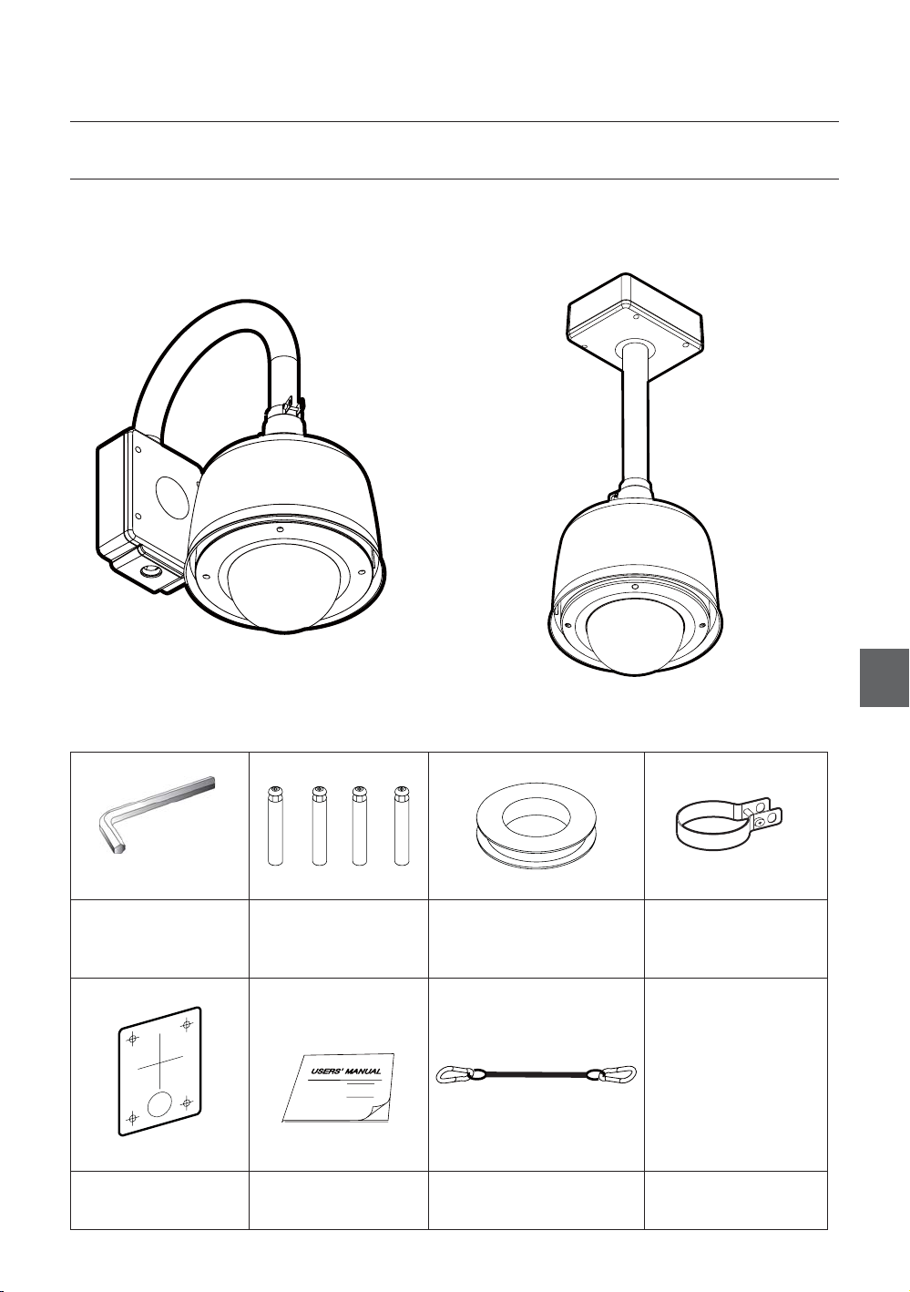
УСТРОЙСТВО И ПРИНАДЛЕЖНОСТИ
Продукт
❖
Введение
Вариант для установки на стенеВариант для установки на стене
Принадлежности
❖
Шестигранный гаечный
ключ
Анкерные болты
(4 шт.)
Водонепроницаемая лента
RUS
Держатель
предохранительного троса
корпуса
Шаблон для
сверления отверстий
Руководство
пользователя
Крепежный трос
Pyccкий – 7
Page 41

Введение
НАИМЕНОВАНИЕ ДЕТАЛИ И ФУНКЦИИ
СВЕТОЗАЩИТНАЯ БЛЕНДА
И ВЕРХНИЙ КОРПУС
PTZ МЕХАНИЗМ
КРЕПЕЖНЫЙ ТРОС КУПОЛА
КАБЕЛЬ ВЕНТИЛЯТОРА И
ВЕНТИЛЯТОР
НАГРЕВАТЕЛЬНЫЙ
ПРИБОР
НАГРЕВАТЕЛЬНОГО
ПРИБОРА
КРЫШКА КУПОЛА
ВНУТРЕННИЙ БЛОК
ДЕРЖАТЕЛЬ КРЕПЕЖНОГО ТРОСА КОРПУСА
Крышка купола
•
Во избежание появления царапин и грязи на куполе
снимите защитную виниловую пленку с крышки
купола только после завершения процесса установки
камеры.
В крышку купола встроены вентилятор и
нагревательный прибор для удаления влаги с купола.
Светозащитная бленда и верхний корпус
•
Светозащитная бленда защищает крышку купола от
солнечных лучей и дождя. Верхняя часть корпуса
камеры, в которой находится встроенный PTZ
механизм, расположена в светозащитной бленде.
Также, верхняя часть корпуса соединяется с
монтажными кронштейнами и крышкой купола.
Настенные/потолочные крепежные кронштейны
•
Они предназначены для установки камеры на стене
или потолке и к ним прилагается распределительная
коробка. В распределительную коробку кронштейна
встроен внутренний блок.
Внутренний блок
•
Внутренний блок осуществляет много важных
функций соединительной коробки, которая
поддерживает связь между камерой и внешней
средой. В верхней части коробки расположены
dip-переключатели и клеммные колодки для
подключения питания, видео, связи и для входа/
выхода сигнала тревоги.
8 – КУПОЛЬНАЯ КАМЕРА 36x
Page 42

УСТАНОВКА DIP-ПЕРЕКЛЮЧАТЕЛЯ
Установка
❖
Настройка протокола связи
Прежде чем устанавливать камеру необходимо
установить DIP-переключатели для настройки ИД
камеры, протокола связи.
w
Протокол
Автопротокол
WWWGaGhGw
WWXGaGwTk
WWYGaGwTw
WWZGaGzhtz|un
Настройка ИД (1 - 255)
pkGzGOX¥Y\\P
Настройка параметра “ИД камеры”
❖
ON
ON
123456
iGy
Скорость в бодах
WWWGaGY[WW
WWXGaG[_WW
WWYGaG`]WW
WWZGaGX`YWW
WW[GaGZ_[WW
RS-485
yzT[_\
Завершение
{
78
ON
ON
123456
Выберите соответствующий протокол с помощью
•
78
сочетания DIP-переключателей.
Состояние переключателя
Штырек1 Штырек2 Штырек3 Штырек4
ВЫК ВЫК ВЫК ВЫК Автопротокол
ВКЛ ВЫК ВЫК ВЫК PELCO-D
ВЫК ВКЛ ВЫК ВЫК PELCO-P
ВКЛ ВКЛ ВЫК ВЫК SAMSUNG
•
Если вы установите для протокола значение
Протокол
“Автопротокол”, камера будет автоматически
распознавать вид протокола.
•
Если вы желаете управлять, используя устройство
DVR или клавиатуру системы, то необходимо, чтобы
их протоколы совпадали с протоколами камеры.
Иначе вы не сможете управлять камерой.
•
Если вы сменили протокол камеры, поменяв DIPпереключатели, то необходимо перезагрузить камеру
для сохранения настроек.
•
Заводской настройкой по умолчанию для протокола
является протокол “Авто”.
Настройка скорости связи в бодах
❖
RUS
ИД номер камеры устанавливается при помощи
•
двойных чисел. Ниже приведен пример.
Штырек 1 2 3 4 5 6 7 8
Значение ИД
ex) ID=5
ex) ID=10
•
Диапазон ИД от 0 до 255. Заводская настройка по
1 2 4 8 16 32 64 128
Вкл
Выкл
Вкл
Выкл
Выкл
Выкл
Выкл
Выкл
Вкл
Выкл
Вкл
Выкл
Выкл
Выкл
умолчанию для ИД камеры - 1.
•
Если требуется управлять конкретной камерой,
необходимо чтобы ИД камеры совпал с
установкой ИД камеры на устройстве DVR или
контроллере.
Выкл
Выкл
ON
ON
123456
•
Выберите соответствующее значение скорости в
78
бодах с помощью сочетания DIP-переключателей.
Состояние переключателя
Штырек5 Штырек6 Штырек7
ВЫК ВЫК ВЫК 2400 бит/с
ВКЛ ВЫК ВЫК 4800 бит/с
ВЫК ВКЛ ВЫК 9600 бит/с
ВКЛ ВКЛ ВЫК 19200 бит/с
ВЫК ВЫК ВКЛ 38400 бит/с
Заводская настройка по умолчанию для скорости
•
Протокол
в бодах - “9600 бит/с”.
Pyccкий – 9
Page 43

Установка
A
Согласующий резистор RS-485
❖
ON
ON
123456
Штырек 8 используется для включения/выключения
•
78
оконечной нагрузки RS-485.
Обычно он должен быть выключен. Однако, в
случае возникновения проблемы с длинным
последовательным подключением, необходимо
включить данный переключатель на последней камере.
Штырек 8 Согласующий резистор RS-485
–
(Вкл/Выкл)
УСТАНОВКА С ИСПОЛЬЗОВАНИЕМ
КРЕПЕЖНОГО КРОНШТЕЙНА
① С помощью бумажного шаблона отметьте место
для отверстий на стене.
③ Надежно установите настенный крепежный
кронштейн на болты. Затяните гайки крепежных
болтов.
② После того как просверлены отверстия,
необходимо вставить в них крепежные болты.
10 – КУПОЛЬНАЯ КАМЕРА 36x
④ Подключите кабели к клеммным колодкам
и разъемам ВNC во внутреннем блоке
распределительной коробки. Проверьте
подключение кабеля в следующей секции.
Протокол, адрес
Protocol,
DIP-переключателя
Address DIP
RS-485
RS-485
Connector to the dome camera
Разъем для купольной камеры
POWER
ПИТАНИЕ
BNC
Выходной разъем
VIDEO
BNC VIDEO
(Видео)
LARM
СИГНАЛ
Page 44

⑤
После того как крепежный трос продет в отверстие
трубки [1], прикрепите верхнюю часть корпуса к
настенному крепежному кронштейну, прокручивая
ее не менее 7 оборотов [2]. Для закрепления
положения верхней части корпуса, крепко
затяните по часовой стрелке ходовые гайки [3].
Установка
⑦ Надлежащим образом подключите кабель,
идущий из распределительной коробки. После
проверки положения разъема для быстрого
подключения, вставьте PTZ механизм в зацеп в
верхней части корпуса.
⑥
Откройте крышку купола, чтобы установить
PTZ механизм камеры. Убедитесь, что крышка
купола надежно закреплена внутренним
крепежным тросом. Подсоедините кабели
вентилятора и нагревательного прибора в
разъемы корпуса.
RUS
⑧ Чтобы PTZ механизм не выпадал из корпуса,
защелкните его двумя черными держателями.
G
Pyccкий – 11
Page 45

Установка
⑨ Закройте крышку купола. Следует аккуратно
расположить крышку купола, так, чтобы совпали
все метки.
ٻ
ٻ
ٻ
ٻ
ٻ
ٻ
⑩ Затяните последовательно четыре винта на
крышке корпуса, как показано на рисунке.
ٻ
ٻ
ٻ
1
Чтобы плотнее притянуть крышку, закручивающий
момент должен составлять от 0,5 до 1,0 Н·м (0,37
- 0,73 фунт-сила/фут).
ٻ
ٻ
ٻ
3
4
2
12 – КУПОЛЬНАЯ КАМЕРА 36x
Page 46

РАЗВОДКА КАБЕЛЕЙ
DVR/ Keyboard
DVR/ Keyboard
DVR/ Keyboard
DVR/ Клавивиатура
RS-485
RS-485
RS-485
D+ D- D+
D+ D- D
D+ D-D- D
Connector to the dome camera
Connector to the dome camera
Разъем для купольной камеры
Выходной
BNC
BNC
разъем BNC
VIDEO
VIDEO
VIDEO
(Видео)
Монитор
Monitor
Monitor
Установка
ALARM OU TPUT
ALARM OU TPUT
ALARM OU TPUT
12 34
12 34
12 34
ALARM IN PUT
ALARM IN PUT
ALARM IN PUT
G1234 5678
G1234 5678
G1234 5678
POWER
POWER
POWER
ПИТАНИЕ
NC.
NC.
NC.
Подключение питания
❖
Тщательно проверьте напряжение и допустимый ток, соответствующий номинальной мощности.
•
Номинальная мощность
Диапазон значений входного
напряжения
Потребление тока
24 В переменного тока 19 В - 29 В переменного тока 2,5 A
Связь через RS-485
❖
Для управления PTZ подсоедините данную электрическую цепь к клавиатуре или устройству DVR. Чтобы
•
управлять одновременно несколькими камерами, линии связи RS-485 этих камер подключаются параллельно,
как показано на рисунке.
Контроллер клавиатуры/DVR
RUS
Pyccкий – 13
Page 47

Установка
Подключение видео
❖
Подключить с помощью коаксиального кабеля
•
BNC.
Подключение входа сигнала тревоги
❖
Вход датчика
•
Выход сигнала тревоги
•
Внутренний блок
Релейная защита
Релейная защита
Макс. 30 В постоянного тока/1A
125 В переменного тока/0,5A
Питание
Внутренний
INTERNAL
блок
a Обратите внимание, что короткое замыкание
между заземлением (GND) и входным контактом
означает активацию сигнала тревоги.
Если необходимо использовать параметр “Вход
сигнала тревоги”, то в экранном меню следует
выбрать тип датчика. Датчики бывают двух
типов: нормально разомкнутые и нормально
замкнутые. Если тип датчика выбран не правильно,
то активация сигнала тревоги будет прямо
противоположной.
IN 1
IN 2
IN 3
IN 4
GND
IN 5
IN 6
IN 7
IN 8
Всего существует 4 выхода сигнала тревоги и
по своему типу все они являются контактами
реле. Поэтому нет необходимости соблюдать
полярность, отслеживать переменный ток/
постоянный ток, и изолировать каналы между
собой. Необходимо внимательнее следить за
мощностью на контактах реле, описанных выше.
14 – КУПОЛЬНАЯ КАМЕРА 36x
Page 48

Эксплуатация
ПУНКТЫ ПРОВЕРКИ ПЕРЕД
НАЧАЛОМ ЭКСПЛУАТАЦИИ
Перед подачей питания тщательно проверьте
•
кабели.
Убедитесь, что ИД камеры, указанный на
•
контроллере, совпадает с ИД управляемой камеры.
ИД камеры можно проверить в разделе “Инфо о
системе” экранного меню.
Если контроллер поддерживает несколько
•
протоколов, то необходимо выбрать протокол,
соответствующий протоколу камеры.
Если вы сменили протокол камеры, поменяв DIP-
•
переключатели, то необходимо перезагрузить
камеру для сохранения настроек.
•
Поскольку способы управления контроллером могут
иметь некоторые отличия для каждой модели, см.
руководство по используемой модели контроллера,
в случае возникновения трудностей с управлением
камеры.
ПРОВЕРКА ФУНКЦИЙ “ПРЕДУСТ” И
“ШАБЛОН”
Ознакомьтесь с управлением параметрами
•
“Предуст”, “Сканир”, “Автопан” и “Шаблон” с
помощью контроллера или устройства DVR, прежде
чем использовать их для применения этих функций
камеры. (См. “Руководство по использованию
клавиатуры системы”)
Если на контроллере или устройстве DVR нет
•
кнопки или функции шаблона, используйте
клавиши быстрого доступа с номерами для функции
предустановки. Для получения дополнительной
информации см. раздел “Резервные предустановки”
данного руководства.
АВТОКАЛИБРОВКА
Если камера постоянно подвергается воздействию
•
высокой температуры (выше 50°C), фокусировка
камеры может пропасть.
В результате изображение будет смазанным. В
данном случае рекомендуется включить функцию
“АВТОКАЛИБРОВКА”, запустив предустановку 165.
Если вы запустили функцию “АВТОКАЛИБРОВКА”,
•
фокус камеры будет калиброваться каждые 6 часов.
Чтобы отключить данную функцию, запустите
предустановку 166.
ЗАПУСК ЭКРАННОГО МЕНЮ
Функция
•
Используя экранное меню можно выполнить
настройку функций “Предуст”, “Шаблон”, “Автопан”,
“Сканир” и выхода сигнала тревоги для каждой
камеры.
Вход в меню
•
<Переход к предустановке> [95]
ЗАРЕЗЕРВИРОВАННЫЕ ПРЕДУСТАНОВКИ
Описание
•
Некоторые номера предустановок зарезервированы
для специальных функций.
Функция
•
<Переход к предустановке> [95]: ввод в экранное меню
<Переход к предустановке> [131 - 134]: запуск функции “Шаблон” 1 - 4
<Переход к предустановке> [141 - 148]: запуск функции “Автопан” 1 - 8
<Переход к предустановке> [151 - 158]: запуск функции “Сканир” 1 - 8
<Переход к предустановке> [161 - 164]: установка для релейных выходов 1 - 4
<Пред.наст.> [161 - 164]: установка для релейных выходов 1 - 4
<Переход к предустановке> [170]: установка для режима камеры BLC
<Переход к предустановке> [171]: установка для режима камеры BLC
<Переход к предустановке> [174]: установка для режима камеры “Режим
<Переход к предустановке> [175]: установка для режима “Режим Фокусир”
<Переход к предустановке> [176]: установка для режима “Режим Фокусир”
<Переход к предустановке> [177]: установка для режима “день/ночь”
<Переход к предустановке> [178]: установка для режима “день/ночь”
<Переход к предустановке> [179]: установка для режима “день/ночь”
<Переход к предустановке> [190]: установка для режима экранного дисплея
<Переход к предустановке> [191]: установка для режима экранного дисплея
<Переход к предустановке> [192]: установка для режима экранного дисплея
<Переход к предустановке> [193]: установка для всех дисплеев маски
<Переход к предустановке> [194]: установка для всех дисплеев маски
<Переход к предустановке> [167]: Джойстик зуммирования “ВКЛ”
<Пред.наст.> [167]: Джойстик зуммирования “ВЫКЛ”
<Переход к предустановке> [200]: Цифровой зум “ВКЛ”
<Переход к предустановке> [201]: Цифровой зум “ВЫКЛ”
значения “ВЫКЛ”
значения “ВКЛ”
значения “ВЫКЛ”
значения “ВЫСОКИЙ”
Фокусир” значения “АВТО”
значения “Ручная”
значения “ПОЛУАВТ”
значения “АВТО 1”
значения “НОЧЬ”
значения “ДЕНЬ”
значения “АВТО”
(кроме маски конфиденциальности)
значения “ВЫКЛ”
(кроме маски конфиденциальности)
значения “ВКЛ”
(кроме маски конфиденциальности)
конфиденциальности значения “ВЫКЛ”
конфиденциальности значения “ВКЛ”
RUS
Pyccкий – 15
Page 49

Эксплуатация
ПРЕДУСТАНОВКА
Функция
•
Можно сохранять как предустановленные максимум
127 положений. Можно назначить номера для
предустановленных значений от 1 до 128, но номер 95
предназначен для запуска экранного меню.
Параметры камеры (например, “Баланс белого”,
“Автоэкспозиция”) могут устанавливаться отдельно для
каждой предустановки и настраиваются с помощью
экранного меню. Одному предустановленному
значению соответствуют четыре релейных выхода.
•
Настройка “Предуст”
<Пред.наст.> [1 - 128]
•
Запуск “Предуст”
<Переход к предустановке> [1 - 128]
•
Удаление функции “Предуст”
Для удаления функции “Предуст” используйте экранное меню.
•
ШАБЛОН
•
•
Удаление функции “Автопан”
Для удаления функции “Автопан” используйте экранное меню.
Функция
Функция “Шаблон” заключается в занесении в память
камеры ее пути передвижения (в большинстве случаев это
кривой путь) с помощью джойстика или контроллера за
назначенный период времени и воспроизведении этого
пути в том виде, в котором он был записан.
Имеются 4 шаблона и максимальное количество команд связи,
которые могут быть сохранены в шаблоне, составляет 1000.
Установка функции “Шаблон”
Создать “Шаблон” можно двумя способами.
Способ 1. <Задать Шаблон> [
–
Экран редактирования шаблона выглядит
следующим образом.
№
Шаблона]
АВТОПАНОРАМИРОВАНИЕ
•
Функция
Для периодического перемещения камеры между
двух предустановленных позиций использовать
функцию автопанорамирования. При запуске функции
“Автопан” камера перемещается по часовой стрелке
из предустановки, обозначенной, как первая точка, к
предустановке, обозначенной, как вторая точка . Затем
камера перемещается из предустановки, обозначенной, как
вторая точка, к предустановке, обозначенной, как первая
точка в направлении против часовой стрелки.
2-я предустановка
Направление по часовой
направление
1-я предустановка
В случае, когда предустановка, обозначенная, как первая
точка аналогична предустановке, обозначенной, как вторая
точка, камера поворачивается по своей оси на 360° в
направлении по часовой стрелке, а затем по своей оси на
360° в направлении против часовой стрелки.
Диапазон скорости, которую возможно установить,
составляет от 1°/сек до 180°/сек.
•
Установка функции “Автопан”
Для установки функции “Автопан” используйте экранное меню.
Запуск функции “Автопан”
•
Способ 1. <Запуск Автопан> [№ Автопан] [Ввод]
Способ 2. <Переход к предустановке> [№ Автопан+140]
Например. Запуск функции “Автопан 2”: <Переход к
предустановке> [142]
против часовой
Способ 2. Через экранное меню: см. раздел
“Использование экранного меню”.
Запуск функции “Шаблон”
•
Способ 1. <Запуск Шаблона> [№ Шаблона] [Ввод]
Например. Запуск “Шаблона 2”: <Запуск
Способ 2. <Переход к предустановке> [№ Шаблона+130]
Например. Запуск “Шаблона 2”: <Переход к
Удаление функции “Шаблон”
•
Для удаления функции “Шаблон” используйте
экранное меню.
ИЗМЕНИТЬ ШАБЛОН 1
[БЛИЗ:СОХР/ ДАЛЕКО:УДАЛ]
Перемещение камеры джойстиком и
–
предустановленное перемещение можно
сохранить в шаблоне.
Оставшийся объем памяти отображается в
–
строке состояния.
–
Для сохранения записи, нажмите кнопку
БЛИЗКО, для удаления - кнопку ДАЛЕКО.
Шаблона> [2] [Ввод]
предустановке> [132]
a Когда функция “ШАБЛОН” сохранена/выполнена,
функция “ПАНОР/НАКЛ” работает с отключенной
функцией “АВТООТРАЗИТЬ”.
0/0/X1/N
16 – КУПОЛЬНАЯ КАМЕРА 36x
Page 50

Эксплуатация
СКАНИРОВАНИЕ
Функция
•
Функция “Сканир” позволяет задать порядок чередования
функций “Предуст”, “Шаблон” и/или “Автопан”. Можно
сохранять максимум 8 операций сканирования. Каждая
операция “Сканир” может состоять максимум из 20
элементов действия, это могут быть “Предуст”, “Шаблон”
или “Автопан”. При установке функции “Сканир” можно
задать предустановленную скорость и число повторений
функций “Шаблон” и “Автопан”. Также можно задать время
задержки между действиями.
Время задержки
Предуст 1
Установка функции “Сканир”
•
Для задания функции “Сканир” используйте экранное меню.
Запуск функции “Сканир”
•
Способ 1. <Запуск Сканир> [№ Сканир] [Ввод]
Способ 2. <Переход к предустановке> [№ Сканир+150]
Например. Запуск “Сканир 7”: <Переход к предустановке> [157]
Удаление функции “Сканир”
•
Для удаления используйте меню экранного дисплея.
Шаблон 1
Максимум 20 элементов
Сканир 1
РАСПИСАНИЕ
Функция
•
Функция “Расписание” позволяет установить запуск
необходимых функций таких, как “Предуст”, “Автопан”,
“Сканир”, “Шаблон”, “Главный” на заданный день недели и
время. Например, если вы установили указание “Вторник 9:00
AM” и “Предуст 1” (предположим, “Главные ворота”), камера
будет перемещаться на главные ворота каждый вторник в 9:00
утра. При установке “День недели” камера будет направляться
на главные ворота каждый день, кроме выходных.
Следует обратить внимание, что благодаря часам реального
времени, установленные данные времени сохранятся
при отключении электропитания. Исходная настойка
дня недели и времени обязательна для правильного
функционирования расписания.
Установка функции “Расписание”
•
Для создания “Расписания” используйте экранное меню.
Запуск функции “Расписание”
•
Используйте экранное меню для включения “Мастера
расписаний”.
Удаление функции “Расписание”
•
Для удаления используйте меню экранного дисплея.
ДРУГИЕ ФУНКЦИИ
Блокировка предустановленных значений
•
Эта функция создана для защиты предустановленных
данных от несанкционированной перезаписи. Если
параметр блокировки предустановленных значений
включен, команда сохранения предустановленных настроек
с использованием комбинаций клавиш отключена, тогда как
сохранения предустановленных настроек с использованием
экранного меню, допустимо.
•
Действие при включении питания
Эта функция позволяет возобновить последнюю операцию,
выполненную до выключения питания. Большинство операций,
таких как предустановка, шаблон, автопанорамирование и
сканирование доступны для этой функции, но возобновление
действий джойстика невозможно.
Если для таких функций, как Предус, Шаблон, Автопан и
Сканир настройки отсутствуют, камера после перезапуска
автоматически переместится в исходное положение.
Если для параметра Дейс при вк.пит установлено значение
“Вкл”, то камера после перезапуска выберет функцию, которая
использовалась в последний раз.
•
Автоотразить
Если угол наклона приходится на самую верхнюю часть
орбиты наклона (90°), камера с модулем зуммирования
продолжает двигаться в противоположном направлении
от наклона (180°), выслеживая объекты. Как только камера
с модулем зуммирования проходит через верхнюю часть
направления наклона (90°), изображение автоматически
переворачивается и на экране появляется буква
Если эта функция находится в режиме “ВЫКЛ”, диапазон
движений наклона варьируется от 0 до 90°.
•
Настройка парковки
Эта функция позволяет автоматически расположить камеру
в определенной позиции, если оператор некоторое
время не управляет контроллером. Время парковки может
определяться, как интервал от 5 секунд до 4 часов.
•
Вход сигнала тревоги
Используется 8 входов сигнала. Если внешний датчик
активирован, камера может быть настроена на движение
в направлении соответствующей предустановки. Обратите
внимание, что последний вход сигнала эффективен, если
активированы несколько датчиков.
•
Выход сигнала тревоги
Существует 4 канала выходов сигнала тревоги и ко всем
может быть присвоен определенный номер функции
“Предуст”. Например, если вы назначаете номер “Предуст
5” для AO2, вызов “Предуст” 5 приведет к включению AO2.
•
Маска зоны конфиденциальности
Для защиты конфиденциальности можно установить
макс. 8 масок конфиденциальности в произвольном
порядке, чтобы скрыть такие объекты, как окна,
магазины или частный дом. С помощью системы
.
F
Pyccкий – 17
RUS
Page 51

Эксплуатация
вычисления сферических координат возможно усиление
функции маски зоны конфиденциальности.
Настройка изображения ОБЩИЕ/СПЕЦИАЛЬНЫЕ
•
WB (Баланс белого) и AE (Автоэкспозиция) могут
устанавливаться отдельно для каждой предустановки.
Существует 2 режима - “Общий” и “Специальный”. Общий
режим означает, что баланс белого или автоэкспозиция
могут устанавливаться полностью и одновременно для
всех предустановок в меню “НАСТР КАМЕРЫ С ТРАНСФ”.
Специальный режим означает, что баланс белого или
автоэкспозиция могут устанавливаться независимо или
отдельно для каждой предустановки в предустановке
меню. В специальном режиме значения баланса белого и
автоэкспозиции должны запускаться соответственно, когда
камера достигает каждого местоположения предустановки.
Во время работы джойстика должны применяться значения
баланса белого/автоэкспозиции в общем режиме. Все значения
WB/AE (баланс белого/автоэкспозиция) в специальном режиме
не изменятся, а в общем режиме изменятся.
Полуавтоматический фокус
•
Этот режим используется для автоматической перестановки
режима фокусировки между ручным режимом фокусировки
и режимом автоматической фокусировки при работе. Ручной
режим фокусировки включается при работе функции “Предуст”;
ИД камеры
•
Текущий ИД камеры (Адрес).
Название операции
•
Следующий перечень представляет собой
возможные названия операций и их значения.
“ПРЕД.НАСТ. ×××”
“ПРЕДУСТ ×××”
“ШАБЛОН ×”
“АПН×/ПРЕДУСТ ×××”
“НЕИЗВЕСТНЫЙ”
•
Предустановленная метка
Метка, сохраненная для определенной функции “Предуст”.
Информация о сигналах
•
Эта информация отображает текущее состояние
входа сигнала. Буква I означает вход, а буква O
- выход. Если функция “Вход” находится в режиме
ВКЛ, на экране отобразится количество входов. Если
функция “Вход” находится в режиме ВЫКЛ, на экране
отобразиться значок “-”. Аналогично запись “O: 1”
означает вход 1 в режиме ВКЛ и “O: -” - ВЫКЛ.
Пример. Когда для точки 2 входы находятся в режиме
ВКЛ и выход 1 также Вкл, на экранном меню отобразиться
следующее:
режим автоматической фокусировки включается при работе
джойстика. При ручном режиме в предустановках, данные
фокусировки заранее сохраняются в каждой предустановке,
и камера запрашивает данные фокусировки в соответствии
с предустановками, как только достигает параметра
предустановки. Это сокращает время получения фокусировок.
Режим фокусировки автоматически меняется на режим
автоматической фокусировки при начале работы джойстика.
ЭКРАННОЕ МЕНЮ ОСНОВНОГО ЭКРАНА
•
Отражение изображения
Отображает, что изображения на данный момент
перевернуты с помощью функции АВТООТРАЗИТЬ.
Дата/Время
•
Отображает текущую дату и время.
Предустановленная
метка 1
Дата/Время
ИД камеры
Отражение изображения
Данные P/T/Z
•
МЕТКУ12345
ИД камеры
ПРЕДУСТ1
Данные P/T/Z
Текущий угол панорамирования/наклона, измеряемый в
градусах, увеличение и направление компаса.
18 – КУПОЛЬНАЯ КАМЕРА 36x
Название
операции
Информация о
сигналах
ОБЩИЕ ПРАВИЛА ПРИ РАБОТЕ С МЕНЮ
Элементы меню, обозначенные < >, всегда состоят из
•
подменю.
Чтобы отобразить все уровни меню, зайдите в подменю и
•
нажмите БЛИЗКО или кнопку Ввод.
Чтобы перейти в меню на уровень вверх, нажмите кнопку
•
ДАЛЕКО.
Чтобы переходить с одного элемента на другой в меню,
•
используйте джойстик в направлениях (вверх/вниз)или
(вправо/влево).
Чтобы поменять значение элемента, используйте
•
положения вверх/вниз джойстика в контроллере.
Нажмите БЛИЗКО или кнопку Ввод, чтобы сохранить
•
значения и кнопку ДАЛЕКО, чтобы отменить значения.
Page 52

Использование экранного меню
ГЛАВНОЕ МЕНЮ
ОСНОВНОЕ МЕНЮ
<ИНФО О СИСТЕМЕ>
<НАСТРОЙКА ИЗОБР>
<НАСТРОЙКА ДВИЖЕНИЯ>
<НАСТРОЙКА ФУНКЦИИ>
<НАСТР КАМЕРЫ С ТРАНСФ>
<НАСТРОЙКА СИСТЕМЫ>
<ИНИЦИАЛ СИСТЕМУ>
ВЫХОД
Информация о системе
•
Отображает информацию и текущие конфигурации.
Настройка изображения
•
Включает/выключает экранное меню основного экрана.
•
Настройка движения
Настройка параметров, касающихся движения.
•
Настройка функции
Настройка различных функций, таких как
предустановка, шаблоны, автопанорамирование,
сканирование и расписание.
•
Настройка камеры
Настройка функций, касающихся камеры и времени.
•
Настройка системы
Настройка основных настроек системы.
•
Инициализировать систему
Инициализирует конфигурации системы и устанавливает
все данные о конфигурации заводских настроек.
ИНФОРМАЦИЯ О СИСТЕМЕ
ИНФО О СИСТЕМЕ
ВЕР МИРОКПРОГР 1.00S36
СИСТЕМ ЦВЕТА NTSC
ПРОТОКОЛ SAMSUNG
СКОР.В БОДАХ 9600
АДРЕС 255
НАСТРОЙКА ИЗОБРАЖЕНИЯ
НАСТРОЙКА ИЗОБР
ИД КАМЕРЫ ВКЛ
ДАННЫЕ PTZ АВТО
НАЗВАНИЕ ОПЕРАЦИИ
МЕТКА ПРЕДУСТ АВТО
В/В СИГНАЛА АВТО
ДАТА/ВРЕМЯ ВКЛ
<ЗОНА КОНФ>
НАЗАД
ВЫХОД
Это меню используется для включения/выключения
экранного меню основного экрана. Если для элемента
установлено значение АВТО, элемент отображается
только, если его значение поменялось.
•
ИД камеры [ВКЛ/ВЫКЛ]
•
Данные PTZ [ВКЛ/ВЫКЛ/АВТО]
•
Название операции [ВКЛ/ВЫКЛ/АВТО]
Предустановленная метка
•
В/В СИГНАЛА [ВКЛ/ВЫКЛ/АВТО]
•
Дата/Время [ВКЛ/ВЫКЛ]
•
<ЗОНА КОНФ>
•
АВТО
[ВКЛ/ВЫКЛ/АВТО]
Запускает меню настройки “Маска
зоны конфиденциальности”
НАСТРОЙКА “МАСКА ЗОНЫ
КОНФИДЕНЦИАЛЬНОСТИ”
Выберите область на изображении, которую вы хотите
замаскировать.
Номер маски [от 1 до 8]
•
ЗОНА КОНФ
НОМЕР МАСКИ 1
ДИСПЛЕЙ ВЫК
УДАЛИТЬ МАСКУ ОТМЕНА
<ИЗМЕНИТЬ МАСКУ>
НЕИЗВЕСТНЫЙ
RUS
НАЗАД
ВЫХОД
•
ВЕР МИРОКПРОГР
Отображает текущие версии микропрограммы камеры.
•
Система цвета
Отображает текущую аналоговую видео систему камеры.
•
Протокол
Отображает текущий протокол для управления PTZ.
•
Скорость в бодах Отображает текущую скорость в
бодах управления PTZ.
•
Адрес Отображает текущий ИД камеры
для управления PTZ.
НАЗАД
ВЫХОД
Выберите номер маски. Если выбранная маска уже
обладает данными, камера перемещается согласно
настройке. В противном случае под пунктом “Номер
маски” отобразиться надпись “НЕИЗВЕСТНЫЙ”.
Дисплей [ВКЛ/ВЫКЛ]
•
Устанавливает, накладывает ли камера маски на
изображения или нет.
Удалить маску [ОТМЕНА/ОК]
•
Удаляет данные в номере выбранной маски.
Pyccкий – 19
Page 53

Использование экранного меню
❖
Настройка “Область зоны конфиденциальности”
НАСТРОЙКА ДВИЖЕНИЯ
ИЗМЕНИТЬ МАСКУ 1
ПЕРЕМЕСТИТЬ В КОН.ПОЛОЖ.
[БЛИЗКО:ВЫБР/ДАЛЕКО:ОТМ]
0/0/x1/N
Перемещает камеру в область, которую нужно
замаскировать. Затем появится меню для настройки
размера маски.
Если угол наклона находится в диапазоне от 90°
до 90°, можно задать настройки для зоны маски
конфиденциальности.
Если задан угол наклона, превышающий 90°
(область перевернутого изображения), камера
автоматически переместиться в идентичное
положение, меняя угол наклона менее чем на 90° и
соответственно угол панорамирования на 180°.
❖
Настройка “Размер зоны конфиденциальности”
ИЗМЕНИТЬ МАСКУ 1
[МАСШТАБ:ИЗМЕНИТЬ ЦВЕТ]
[◄►:НАСТР ШИРИНУ МАСКИ]
[▲▼:НАСТР ВЫСОТУ МАСКИ]
[БЛИЗКО:СОХР/ДАЛЕКО:ОТМ]
Настройте размер маски. Используйте джойстик или
кнопки со стрелками, чтобы настроить размер маски.
◄► (Вправо/влево) Настраивает ширину маски.
•
▲▼ (Вверх/Вниз) Настраивает высоту маски.
•
Увеличение/уменьшение Изменяет цвет маски.
•
Чтобы полностью замаскировать определенную
зону, независимо от высокой скорости
перемещения в режиме панорамирования/наклона,
рекомендуется выбирать размер маски на 20%
больше, чем исходный размер объекта.
Следует иметь в виду, что во время операции
управления панорамированием/наклоном объект
за маской конфиденциальности может на короткое
время быть скрыт.
НАСТРОЙКА ДВИЖЕНИЯ
БЛОК. ПРЕДУСТ ВЫК
ДЕЙС ПРИ ВК.ПИТ ВКЛ
АВТООТРАЗИТЬ ВКЛ
МАКС.СКОР.ДЖ 140/СЕК
НАПРАВЛ ДЖ ИНВЕРС
ПАУЗА НАСТР ВЫК
<НАСТРОЙКА ПАРКОВКИ>
<НАСТР. ВХОДА СИГНАЛА>
НАЗАД
ВЫХОД
Настройка основных функций перемещений в режиме
панорамирование/наклон.
Блокировка предустановленных значений
•
[ВКЛ/ВЫКЛ]
Если для параметра Блок. предуст установлено значение
Вкл, то невозможно настроить или удалить настройки
Предус, Автопан, Шаблон и Сканир. Возможно только
запустить эти функции. Чтобы настроить или удалить эти
функции, зайдите в экранное меню.
Действие при включении питания
•
[ВКЛ/ВЫКЛ]
См. раздел “Другие функции” (стр.17).
Автоотразить [ВКЛ/ВЫКЛ]
•
См. раздел “Другие функции” (стр.17).
Максимальная скорость джойстика
•
[от 2°/сек до 200°/сек]
Устанавливает максимальную скорость джойстика. Скорость
джойстика обратно пропорциональна коэффициенту
зуммирования. При повышении значения увеличения,
скорость панорамирования/наклона снижается.
Направление джойстика [ИНВЕРС/ОБЫЧНОЕ]
•
Если установлено значение “Обычное”, изображение
на экране перемещается в направлении наклона
джойстика. Если выбран “Инверс”, изображение на экране
перемещается в противоположном направлении.
Пауза в предустановке [ВКЛ/ВЫКЛ]
•
В начале предустановленного движения, камера
фиксирует изображение исходного положения. На камере
отображается изображение исходного положения во
время предустановленного движения; изображения,
полученные во время предустановленного движения,
не отображаются. Как только камера останавливается по
окончании предустановленного момента, изображения в
режиме реального времени, полученные по окончании
предустановленного момента, начинают отображаться на
камере.
20 – КУПОЛЬНАЯ КАМЕРА 36x
Page 54

Использование экранного меню
Настройка парковки
❖
НАСТРОЙКА ПАРКОВКИ
ВКЛ ПАРКОВКУ ВЫК
ВРЕМЯ ОЖИДАНИЯ
ПАРКОВКА ГЛАВНЫЙ
НАЗАД
ВЫХОД
00:10:00
Если включение настройки парковки находится в
режиме ВКЛ, камера запускает заданные функции
автоматически, если не поступает команды PTZ во
время действия команды “Время ожидания”.
Включение парковки [ВКЛ/ВЫКЛ]
•
Время ожидания [от 5 сек до 4 часов]
•
Время отображается в формате “hh:mm:ss” и его
можно изменять посекундно.
Парковка
•
[ГЛАВНЫЙ/ПРЕДУСТ/ШАБЛОН/АВТОПАН/СКАНИР]
Пример. Если для парковки выбран параметр
ГЛАВНЫЙ, камера переместиться в начальное
положение, если не поступит команды PTZ во
время действия команды “Время ожидания”.
Настройка входа сигнала
❖
НАСТР. ВХОДА СИГНАЛА
СИГНАЛ1 Н.Р. ПРЕДУСТ1
СИГНАЛ2 Н.Р.
СИГНАЛ3 Н.Р.
СИГНАЛ4 Н.Р.
СИГНАЛ5 Н.Р. ПРЕДУСТ1
СИГНАЛ6 Н.Р.
СИГНАЛ7 Н.Р.
СИГНАЛ8 Н.Р.
НАЗАД
ВЫХОД
НЕ ИСПОЛЬЗУЕТСЯ
НЕ ИСПОЛЬЗУЕТСЯ
НЕ ИСПОЛЬЗУЕТСЯ
НЕ ИСПОЛЬЗУЕТСЯ
НЕ ИСПОЛЬЗУЕТСЯ
НЕ ИСПОЛЬЗУЕТСЯ
Убедитесь в совпадении датчика тревоги с одним
из положений предустановки. Если внешний
датчик активирован, камера переместиться в
соответствующее положение предустановки, когда
этот элемент предварительно задан.
Тип сигнала тревоги
•
[НОРМ РАЗОМКНУТОЕ (Н.Р)/ НОРМ ЗАМКНУТОЕ (Н.З)]
Устанавливает тип входа датчика.
Операция “Сигнал тревоги”
•
[НЕ ИСПОЛЬЗУЕТСЯ/ГЛАВНЫЙ/ПРЕДУСТ от 1 до 128/
АВТОП от 1 до 8, ШАБЛОН от 1 до 4, СКАНИР от 1 до 4]
Для каждого входа сигнала тревоги вы
можете установить функцию противодействия
(“Предуст”, “Шаблон”, “Автопан”, “Сканир”).
НАСТРОЙКА ФУНКЦИИ
НАСТРОЙКА ФУНКЦИИ
<ПРЕДВАРИТ НАСТРОЙКА>
<НАСТРОЙКА АВТОПАНОР>
<НАСТРОЙКА ШАБЛОНА>
<НАСТРОЙКА СКАНИР>
<НАСТРОЙКА РАСПИСАНИЯ>
НАЗАД
ВЫХОД
Настройте 5 специальных функций с помощью данного
меню.
Предварительная настройка
•
К 127 предустановкам могут присваиваться номера
от 1 до 128, за исключением предустановки 95,
предназначенной для меню.
Настройка автопанорамирования
•
Использование до 8 автопанирований позволяет
камере медленно перемещаться между двумя
заданными точками.
Настройка шаблона
•
В куполе можно хранить до 4 шаблонов.
В данной функции путь сохранения данных,
создаваемый ручным движением джойстика,
сохраняется, и при необходимости вы можете
автоматически воспроизвести идентичный путь.
Настройка сканирования
•
Можно разграничить до 8 операций сканирования.
В функции “Сканир” можно задать максимум 20
элементов для любой из комбинаций: “Предуст”/
”Автопан”/”Шаблон”. Если вы запускаете функцию
“Сканирование”, камера последовательно выполнит
все команды.
Настройка расписания
•
В расписании можно задать 7 указаний по
дням недели и времени. Для каждого указания
можно задать соответствующие функции (такие,
как “Главный”, “Предуст”, “Сканир”, “Шаблон”
и “Автопан”). Также, для упрощения указания,
возможно, использовать настройки “День недели” и
“Все дни”.
RUS
Pyccкий – 21
Page 55

Использование экранного меню
ПРЕДВАРИТЕЛЬНАЯ НАСТРОЙКА
ПРЕДВАРИТ НАСТРОЙКА
№ УСТАН. 1
<ИЗМЕНИТЬ СЦЕНУ>
<МЕТКУ> WINDOWS
УДАЛИТЬ НАСТР ОТМЕНА
НАСТРОЙКА КАМ ОБЩИЕ
ВЫХОД СИГНАЛА ----
НАЗАД
ВЫХОД
Номер предустановки [от 1 до 128]
•
Если выбранная предустановка уже определена, камера
перемещается в предопределенное положение и
параметры предустановки, такие, как “Метка” и “Релейные
выходы”, отображаются на мониторе.Если выбранная
предустановка не определена, на мониторе отображается
надпись “НЕИЗВЕСТНЫЙ”.
Изменить сцену
•
Переопределите текущее положение предустановленной
сцены (т.е. PTZ).
Метку
•
Изменяет метку, чтобы отобразить на мониторе, когда
запускаются предустановки. МАКС. допустимо 10 букв.
Удалить настр [ОТМЕНА/OK]
•
Удаление предустановленных данных
Настройка КАМ [ОБЩИЕ/СПЕЦИАЛЬНЫЕ]
•
WB (баланс белого) и AE (автоэкспозиция) могут
устанавливаться отдельно для каждой предустановки.
Существует 2 режима - “Общий” и “Специальный”. Общий
режим означает, что баланс белого или автоэкспозиция
могут устанавливаться полностью и одновременно для всех
предустановок в меню “НАСТР КАМЕРЫ С ТРАНСФ”.
Специальный режим означает, что баланс белого или
автоэкспозиция могут устанавливаться независимо или
отдельно для каждой предустановки в предустановке
меню. В специальном режиме значения баланса белого и
автоэкспозиции должны запускаться соответственно, когда
камера достигает каждого местоположения предустановки.
Во время работы джойстика должны применяться значения
баланса белого/автоэкспозиции в общем режиме.
Все значения WB/AE (баланс белого/автоэкспозиция)
в специальном режиме не изменяются, а в общем
режиме изменяются. Если выбран режим “Специальный”,
отображается меню для установки WB/AE (баланс белого/
автоэкспозиция)
Выход сигнала
•
Состояние четырех выходов сигнала тревоги можно легко
контролировать вместе с запуском функции “Предуст”.
22 – КУПОЛЬНАЯ КАМЕРА 36x
Символ “ - “ означает состояние “ВЫКЛ”, а номер,
представляющий каждый бит - “ВКЛ”.
Пример. Если установлено значение -23-, то при запуске
этой предустановки, релейные выходы 2, 3 будут включены,
а 1, 4 - выключены.
Изменить предустановленную сцену
❖
ИЗМЕНИТЬ СЦЕНУ - ПРЕДУСТ 1
ПЕРЕМЕСТИТЬ В КОН.ПОЛОЖ.
[БЛИЗКО:СОХР/ДАЛЕКО:ОТМ]
0/0/x1/N
① Используя джойстик, переместите камеру в
необходимое положение.
② Нажмите БЛИЗКО или кнопку Ввод, чтобы
сохранить текущие данные PTZ.
③ Нажмите кнопку ДАЛЕКО для отмены.
Изменить предустановленную метку
❖
МЕТКУ - ПРЕДУСТ 1
[█ ]
--------- 1234567890 OK
ABCDEFGHIJ ОТМЕНА
KLMNOPQRST
UVWXYZabcd
efghijklmn
opqrstuvwx
yz<>-/:.
① Изменяет метку, чтобы отобразить на
мониторе момент, когда камера достигает
предустановленных значений. В меню
редактирования метки перевернутый
прямоугольник является курсором. По
окончании выбора буквы, курсор перемещается
к следующей цифре.
[ ]
Текущее положение курсора
② Используя положения вверх/вниз/влево/вправо
джойстика, переместитесь к нужному символу
из набора символов. Для выбора символа,
нажмите БЛИЗКО или кнопку Ввод.
Page 56

Использование экранного меню
При запуске функции “Автопан” камера
перемещается по часовой стрелке из предустановки,
обозначенной, как первая точка, к предустановке,
обозначенной, как вторая точка . Затем камера
перемещается из предустановки, обозначенной,
как вторая точка, к предустановке, обозначенной,
как первая точка в направлении против часовой
Символ BackSpace (возврат)
Символ пробела
Если вы хотите использовать пробел, выберите
символ “ ” (пробел). Если вы хотите удалить символ
впереди, используйте символ возврата “”.
③
Если вы закончили редактирование метки,
переместите курсор к пункту “OK” и нажмите
БЛИЗКО или кнопку Ввод, чтобы сохранить
готовую метку. Чтобы прервать текущее
изменение, переместите курсор к пункту
“Отмена” и нажмите БЛИЗКО или кнопку Ввод.
НАСТРОЙКА АВТОПАНОРАМИРОВАНИЯ
НАСТРОЙКА АВТОПАНОР
№ APAN 1
1Е ПОЛ.
2Е ПОЛ.
СКОР. АВТОП 30/СЕК
УДАЛ АВТОПАН ОТМЕНА
НАЗАД
ВЫХОД
НЕ ИСПОЛЬЗУЕТСЯ
НЕ ИСПОЛЬЗУЕТСЯ
стрелки.
В случае, когда предустановка, обозначенная,
как вторая точка аналогична предустановке,
обозначенной, как первая точка, камера
поворачивается по своей оси на 360° в направлении
по часовой стрелке, а затем по своей оси на 360° в
направлении против часовой стрелки.
Скорость АВТОП (АВТОПАНОРАМИРОВАНИЕ)
•
[от 1°/сек до 180°/сек]
Устанавливает скорость автопанорамирования от
1°/сек до 180°/сек.
Удалить АВТОП (АВТОПАНОРАМИРОВАНИЕ)
•
[ОТМЕНА/OK]
Удаляет текущие данные автопанорамирования.
НАСТРОЙКА ШАБЛОНА
НАСТРОЙКА ШАБЛОНА
НОМЕР ШАБЛОНА 1
УДАЛ. ШАБЛОН
<ИЗМЕНИТЬ ШАБЛОН>
НЕИЗВЕСТНЫЙ
ОТМЕНА
RUS
Номер автопанорамирования [от 1 до 8]
•
Выбирает номер автопанорамирования, который нужно
изменить. Если выбранное автопанорамирование
не определено, в первом и втором положениях
отображается надпись “НЕ ИСПОЛЬЗУЕТСЯ”.
Первое положение/второе положение
•
[ПРЕДУСТ от 1 до 128]
Установка второго положения для функции
“Автопан”. Если выбранная предустановка не
определена, отображается надпись “НЕИЗВЕСТНЫЙ”,
как показано ниже.
НАСТРОЙКА АВТОПАНОР
№ APAN 1
1Е ПОЛ. ПРЕДУСТ5
2Е ПОЛ. ПРЕДУСТ8
НЕИЗВЕСТНЫЙ
НАЗАД
ВЫХОД
Номер шаблона [от 1 до 4]
•
Выбирает номер шаблона, который нужно изменить.
Если выбранный номер шаблона не определен, под
выбранным номером шаблона отображается надпись
“НЕИЗВЕСТНЫЙ”.
Удал. шаблон [ОТМЕНА/OK]
•
Удаляет данные в текущем шаблоне.
Изменить шаблон
•
Начинает изменять шаблон.
Pyccкий – 23
Page 57

Использование экранного меню
Изменить шаблон
❖
① С помощью джойстика перейдите в исходное
положение с соответствующим зуммированием.
Для начала записи шаблона, нажмите БЛИЗКО
или кнопку Ввод. Нажмите кнопку ДАЛЕКО для
выхода.
ИЗМЕНИТЬ ШАБЛОН 1
ПЕРЕМЕСТ. В НАЧ. ПОЛОЖ.
БЛИЗКО:СТАРТ/ДАЛЕКО:ОТМ
[
② Переместите камеру с помощью джойстика
контроллера или запустите функцию
предустановки для занесения пути в память (в
большинстве случаев кривой путь) в выбранном
шаблоне. Общий объем памяти и оставшийся
объем памяти отображается в виде строки.
Максимальное количество команд связи,
которые могут быть сохранены в шаблоне,
составляет 1000.
ИЗМЕНИТЬ ШАБЛОН 1
[БЛИЗ:СОХР/ ДАЛЕКО:УДАЛ]
0/0/x1/N
0/0/X1/N
]
НАСТРОЙКА СКАНИРОВАНИЯ
НАСТРОЙКА СКАНИР
НОМЕР СКАНИР 1
УДАЛИТЬ СКАН ОТМЕНА
<ИЗМЕНИТЬ СКАНИР>
НАЗАД
ВЫХОД
Номер сканирования [от 1 до 8]
•
Выбирает номер сканирования, который нужно изменить.
Если выбранный номер сканирования не
определен, под выбранным номером сканирования
отображается надпись “НЕИЗВЕСТНЫЙ”.
Удалить сканирование [ОТМЕНА/OK]
•
Удаляет данные в текущем сканировании.
Изменить сканирование
•
Начинает изменять сканирование.
Изменить сканирование
❖
① Нажмите БЛИЗКО или кнопку Ввод в
списке с номерами, чтобы начать установку
сканирования.
ИЗМЕНИТЬ СКАНИР 1
№ ДЕЙСТВ № ПАУЗА ПАР
1 НЕТ
2 НЕТ
3 НЕТ
4 НЕТ
5 НЕТ
СОХР
ОТМЕНА [БЛИЗКО:ИЗМ]
НЕИЗВЕСТНЫЙ
③ Для сохранения данных и для выхода нажмите
БЛИЗКО или кнопку Ввод. Для отмены записи
и удаления записанных данных нажмите кнопку
ДАЛЕКО.
24 – КУПОЛЬНАЯ КАМЕРА 36x
②
Следует заметить, что МАКС. количество
функций, допустимых в сканировании, составляет
20. Переместите курсор вверх/вниз и нажмите
БЛИЗКО или кнопку Ввод для установки.
ИЗМЕНИТЬ СКАНИР 1
№ ДЕЙСТВ № ПАУЗА ПАР
1 НЕТ
2 НЕТ
3 НЕТ
4 НЕТ
5 НЕТ
СОХР [БЛИЗКО:ИЗМ Д]
ОТМЕНА [ДАЛ:ИЗМ КОНЕЦ]
Page 58

Использование экранного меню
③
Установка элементов: операция, время задержки
и дополнительный параметр. Обратите внимание,
что выбранный элемент отображается в обратном
порядке. Перемещайте курсор вправо/влево,
чтобы выбрать элементы и вверх/вниз, чтобы
поменять значение каждого из них.
⑤
После окончания установки операции нажмите
БЛИЗКО или кнопку Ввод, чтобы перейти
на один уровень в меню вверх (шаг ②).
Перемещайте курсор вверх/вниз, чтобы выбрать
номер операции и повторить шаги со ② по ④ ,
чтобы изменить выбранное сканирование.
ИЗМЕНИТЬ СКАНИР 1
№ ДЕЙСТВ № ПАУЗА ПАР
1 НЕТ
2 НЕТ
3 НЕТ
4 НЕТ
5 НЕТ
СОХР [◄►:ПЕРЕМ.КУРС]
ОТМЕНА [▲▼:ИЗМ ЗНАЧ.]
Номер операции
•
[НЕТ/ПРЕДУСТ/АВТОПАН/ШАБЛОН]
Пауза [от 1 секунд до 4 минут]
•
Устанавливает время задержки между
функциями.
ПАР
•
Дополнительный параметр. Он отображает
предустановленную скорость (от 2 до 360),
когда выбрана предустановка. Он отражает
количество повторов (от 1 до 255), когда
в качестве операции выбрана функция
“Шаблон” или “Автопанорамирование”.
④ Настройка таких элементов, как операция,
номер, пауза и пар.
ИЗМЕНИТЬ СКАНИР 1
№ ДЕЙСТВ № ПАУЗА ПАР
1 ПРЕДУСТ 1 00:03 360
2 НЕТ
3 НЕТ
4 НЕТ
5 НЕТ
СОХР [БЛИЗКО:ИЗМ Д]
ОТМЕНА [ДАЛ:ИЗМ КОНЕЦ]
⑥ После окончания установки всех операций
нажмите кнопку ДАЛЕКО для выхода.
Переместите курсор к кнопке СОХР. Нажмите
БЛИЗКО или кнопку Ввод для сохранения
данных.
ИЗМЕНИТЬ СКАНИР 1
№ ДЕЙСТВ № ПАУЗА ПАР
1 ПРЕДУСТ 1 00:03 360
2 НЕТ
3 НЕТ
4 НЕТ
5 НЕТ
СОХР
ОТМЕНА
RUS
ИЗМЕНИТЬ СКАНИР 1
№ ДЕЙСТВ № ПАУЗА ПАР
1 ПРЕДУСТ 1 00:03 360
2 НЕТ
3 НЕТ
4 НЕТ
5 НЕТ
СОХР [◄►:ПЕРЕМ.КУРС]
ОТМЕНА [▲▼:ИЗМ ЗНАЧ.]
Pyccкий – 25
Page 59

Использование экранного меню
НАСТРОЙКА РАСПИСАНИЯ
НАСТРОЙКА РАСПИСАНИЯ
ВКЛ ГЛАВНЫЙ ВКЛ
ДЕНЬ ВРЕМЯ ДЕЙ № ВКЛ
1 НЕИЗВЕСТНЫЙ
2 НЕИЗВЕСТНЫЙ
3 НЕИЗВЕСТНЫЙ
4 НЕИЗВЕСТНЫЙ
5 НЕИЗВЕСТНЫЙ
6 НЕИЗВЕСТНЫЙ
7 НЕИЗВЕСТНЫЙ
НАЗАД
Включить главный [ВКЛ/ВЫКЛ]
•
Определяет, активна ли функция расписание или нет.
Изменение расписания
❖
① После того как вы переместили курсор к
номеру, используя кнопки вверх/вниз, нажмите
кнопку БЛИЗКО(Ввод), чтобы произвести
изменения.
НАСТРОЙКА РАСПИСАНИЯ
ВКЛ ГЛАВНЫЙ ВКЛ
ДЕНЬ ВРЕМЯ ДЕЙ № ВКЛ
1 НЕИЗВЕСТНЫЙ
2 НЕИЗВЕСТНЫЙ
3 НЕИЗВЕСТНЫЙ
4 НЕИЗВЕСТНЫЙ
5 НЕИЗВЕСТНЫЙ
6 НЕИЗВЕСТНЫЙ
7 НЕИЗВЕСТНЫЙ
НАЗАД
Значение каждого значения:
ДЕНЬ Дни: ПНД ВТР СРД ЧТВ ПТН
СБТ ВСК
ВЫХ: день недели
ВСЕ: все дни (каждый день)
ВРЕМЯ 24-часовой формат
ОПЕРАЦИЯ
PRS(Предуст), AUP(Автопан),
PTN(Шаблон), SCN(Сканир),
HOM(Главный)
ВКЛ/ВЫКЛ
Определяет, приводить это указание
в действие или нет
Если вы завершили работу над правилом,
нажмите БЛИЗКО или кнопку Ввод, чтобы
выбрать следующее правило.
Повторите эту процедуру, чтобы до конца
заполнить расписание.
③ Пример.
Второе указание означает, что камера
–
перемещается в положение “Предуст 12” - в
7:35 каждую среду.
НАСТРОЙКА РАСПИСАНИЯ
ВКЛ ГЛАВНЫЙ ВКЛ
ДЕНЬ ВРЕМЯ ДЕЙ № ВКЛ
1 ПНД 01:20 HOM ВКЛ
2 СРД 07:35 НСТ 12 ВКЛ
3 ЧТВ 11:40 ШАБ 3 ВКЛ
4 СБТ 15:17 СЦН 1 ВКЛ
5 ВЫХ 23:00 HOM ВКЛ
6 НЕИЗВЕСТНЫЙ
7 НЕИЗВЕСТНЫЙ
НАЗАД
② Каждое поле можно выбрать, управляя
кнопками вправо/влево, а поменять значения в
поле - с помощью кнопок вверх/вниз.
НАСТРОЙКА РАСПИСАНИЯ
ВКЛ ГЛАВНЫЙ ВКЛ
ДЕНЬ ВРЕМЯ ДЕЙ № ВКЛ
1 ПНД 00:00 HOM ВЫК
2 НЕИЗВЕСТНЫЙ
3 НЕИЗВЕСТНЫЙ
4 НЕИЗВЕСТНЫЙ
5 НЕИЗВЕСТНЫЙ
6 НЕИЗВЕСТНЫЙ
7 НЕИЗВЕСТНЫЙ
НАЗАД
26 – КУПОЛЬНАЯ КАМЕРА 36x
* Примечание. Если есть установки, которые
противоречат друг другу, то чем выше значение,
тем выше приоритет.
* Примечание. Если вы назначаете функцию,
которая не определена, никаких действий не
последует.
* Совет: используя зарезервированную
предустановку, можно составить различные
расписания. Например, PRS179 и PRS178 режим “день” и “ночь” соответственно.
(см. список зарезервированных предустановок,
стр.15 данного руководства.)
Page 60

Использование экранного меню
НАСТРОЙКА КАМЕРЫ
Установка баланса белого
❖
Настройка основных функций модуля зуммирования
камеры
НАСТР КАМЕРЫ С ТРАНСФ
РЕЖИМ ФОКУСИР ПОЛУАВТ
ЦИФРОВОЙ ЗУМ ВКЛ
ОТРАЖ ИЗОБР ВЫК
БЕЗ МЕРЦАНИЯ ВЫК
<НАСТР БАЛАНСА БЕЛОГО>
<НАСТРОЙКА АВТОЭКСП>
НАЗАД
ВЫХОД
Режим фокусировки [АВТО/РУЧНАЯ/ПОЛУАВТ]
•
Устанавливает режим фокусировки камеры.
Режим ПОЛУАВТ
Этот режим используется для автоматической
перестановки режима фокусировки между ручным
режимом фокусировки и режимом автоматической
фокусировки. Ручной режим фокусировки
включается при работе функции “Предуст”; режим
автоматической фокусировки включается при
работе джойстика.
При ручном режиме в предустановках, данные
фокусировки заранее сохраняются в каждой
предустановке, и камера запрашивает данные
фокусировки в соответствии с предустановками,
как только достигает параметра предустановки.
Цифровое зуммирование [ВКЛ/ВЫКЛ]
•
Устанавливает функцию цифрового зуммирования
в режим “ВКЛ/ВЫКЛ”. Если цифровое зуммирование
находится в режиме “ВЫКЛ”, запускается функция
оптического зуммирования и процесс зуммирования
приостанавливается по окончании оптического
увеличения.
Автоотразить [ВКЛ/ВЫКЛ]
•
Отображает перевернутое изображение.
Без мерцания [ВКЛ/ВЫКЛ]
•
Включает или выключает функцию “Без мерцания”
В данной функции режим “Режим АЭ” становится
режимом “Приоритет затвора”, а значение скорости
затвора будет выбрано 1/100 сек.
НАСТР БАЛАНСА БЕЛОГО - GLOBAL
РЕЖИМ БАЛ БЕЛОГО
zНАСТР КРАСН ---
zНАСТР СИНЕГО ---
НАЗАД
ВЫХОД
Режим бал белого [АВТО/РУЧНАЯ]
•
АВТО
В ручном режиме уровень красного и синего может
устанавливаться вручную.
Настройка красного [от 0 до 255]
•
Настройка синего [от 0 до 255]
•
❖
Настройка автоэксп
AE SETUP
ШДД/КСЧ ВСЕ ВЫКЛ
ДЕНЬ/НОЧЬ АВТО
РЕДИМ АЭ АВТО
УРОВ. ДИАФР -- УРОВ. УСИЛ -- СКОР ЗАТВ -- ЯРКОСТЬ ---
НАЗАД
ВЫХОД
ШДД/КСЧ [ВСЕ ВЫКЛ/ШДД ВКЛ/КСЧ ВКЛ]
•
Выбор функции ШДД (широкий динамический
диапазон) или КСЧ (компенсация задней подсветки).
ВСЕ “ВЫКЛ” означает, что обе функции отключены.
День/ночь [АВТО/ДЕНЬ/НОЧЬ]
•
Кнопка АВТО меняет значения день/ночь.
•
РЕЖИМ АЭ АВТО/РУЧНАЯ/ДИАФРАГМА/ЗАТВОР/
ЯРКОСТЬ
АВТО: Полностью автоматический режим для
функции автоэкспозиции
РУЧНАЯ:
в ручном режиме. ДИАФРАГМА, УСИЛЕНИЕ,
СКОРОСТЬ ЗАТВОРА могут изменяться в данном режиме.
ДИАФРАГМА: режим “Приоритет диафрагмы”. Вы
можете изменять режим “Диафрагма”, тогда как
другие настраиваются автоматически.
ЗАТВОР: режим “Приоритет затвора”. Вы можете
изменять скорость затвора, тогда как другие
настраиваются автоматически.
ЯРКОСТЬ: в данном режиме вы можете назначить
значение автоэкспозиции в соответствии с яркостью.
RUS
Pyccкий – 27
Page 61

Использование экранного меню
Диафрагма
•
[работает, когда режим АЭ в режиме РУЧНАЯ или
ДИАФРАГМА]
Диапазон: ЗАКРЫТЬ/F1.6/F2/F2.4/F2.8/F3.4/F4/F4.8/
F5.6/F6.8/F8/ F9.6/F11/F14/F16/F19/F22/F28.
(18 интервалов)
Усиление
•
[работает, когда режим АЭ в режиме РУЧНАЯ]
Увеличивает яркость изображения автоматически в
случае, когда уровень яркости сигнала изображения
очень низкий.
Диапазон: -3/0/2/4/6/8/10/12/14/16/18/20/22/24/26/
28дБ (16 интервалов)
Скорость затвора
•
[работает, когда режим АЭ в режиме РУЧНАЯ или
ЗАТВОР]
X64, X32, X16, X8, X4, X2,1/60,1/90,1/100,1/125,1/
180,1/250,1/350,1/500,1/725,1/1000,1/1500,1/
2000,1/4000,1/6000,1/10000
Яркость
•
[работает, когда режим АЭ в режиме ЯРКОСТЬ]
Настраивает яркость изображения. Режимы
“Диафрагма”, “Скорость затвора” и “Усиление”
настраиваются автоматически в соответствии
с данным значением. Диапазон: от 0 до 31 (32
интервала)
НАСТРОЙКА СИСТЕМЫ
•
•
Обратите внимание, что срок установки даты
УСТАН. ДАТЫ/ВРЕМЕНИ
ДАТА 01/ЯНВ/2008(ВТР)
ВРЕМЯ 00:00:01(Ч/М/С)
НАЗАД
ВЫХОД
Время
Время отображается в формате HH:MM:SS.
Установка ДАТЫ/ВРЕМЕНИ
После нажатия БЛИЗКО или кнопки Ввод можно
выбрать каждое поле с помощью кнопок со
стрелками вправо или влево, а затем изменить
значение в выбранном поле с помощью кнопок
со стрелками вверх или вниз. Чтобы сохранить
обновленные данные, еще раз нажмите БЛИЗКО или
кнопку Ввод.
ограничен с 01.01.2000 до 31.12.2037.
НАСТРОЙКА ТИПА РЕЛЕ
РЕЛЕ1 НОРМ РАЗОМКНУТОЕ
РЕЛЕ2 НОРМ РАЗОМКНУТОЕ
РЕЛЕ3 НОРМ РАЗОМКНУТОЕ
РЕЛЕ4 НОРМ ЗАМКНУТОЕ
НАСТРОЙКА СИСТЕМЫ
<УСТАН. ДАТЫ/ВРЕМЕНИ>
<ТИП РЕЛЕ>
<ПАРОЛЬ>
<ЗАДАТЬ НАЧ.ПОЛОЖ>
<ЗАДАТЬ СЕВЕР НАПРАВ>
ЯЗЫК ENGLISH
НАЗАД
ВЫХОД
Настройка системы
•
Вы можете установить ДАТУ/ВРЕМЯ, ТИП РЕЛЕ,
ПАРОЛЬ, НАЧ ПОЛОЖЕНИЕ, СЕВЕР ПОЛОЖЕНИЕ.
Дата
•
Дата отображается в формате dd/mm/yyyy. День
вычисляется автоматически после установки даты.
28 – КУПОЛЬНАЯ КАМЕРА 36x
НАЗАД
ВЫХОД
Настройка типа реле
•
Разграничивают типы контактов четырехканальных
РЕЛЕЙНЫХ ВЫХОДОВ. (НОРМ РАЗОМКНУТОЕ/НОРМ
ЗАМКНУТОЕ)
НОРМ РАЗОМКНУТОЕ
НОРМ ЗАМКНУТОЕ
Page 62

Использование экранного меню
ИЗМЕНИТЬ ПАРОЛЬ
[█ ]
--------- 1234567890 OK
ABCDEFGHIJ ОТМЕНА
KLMNOPQRST
UVWXYZabcd ВЫКЛ
efghijklmn
opqrstuvwx
yz<>-/:.
----------
УСТАНОВКА ПАРОЛЯ
•
Можно установить пароль, состоящий из 4 символов.
Если данная функция установлена в режиме ВКЛ,
необходимо печатать этот пароль каждый раз, чтобы
войти в экранное меню.
Обратите внимание, что ГЛАВНЫЙ ПАРОЛЬ: “4321”
ЗАДАТЬ НАЧ.ПОЛОЖ
ПЕРЕМЕСТИТЬ В КОН.ПОЛОЖ.
[БЛИЗКО:СОХР/ДАЛЕКО:ОТМ]
Задать начальное положение
•
НАЧАЛЬНОЕ положение означает исходную точку
вычисления угла панорамирования. Значение угла
панорамирования, отображающееся на экране,
зависит от НАЧАЛЬНОГО положения.
С помощью джойстика переместите камеру в нужное
положение и нажмите кнопку Ввод (БЛИЗКО/СОХР).
Следует отметить, что значение положения
“ГЛАВНЫЙ” не действительно для угла наклона.
Если изменить начальное положение, все горизонтальные
положения таких функций, как предустановка, шаблон
сканирование, автопанорамирование и маска зоны
конфиденциальности сдвинутся в соответствии с
изменением начального положения.
Если для таких функций, как Предус, Шаблон, Автопан
и Сканир настройки отсутствуют, камера после
перезапуска автоматически переместится в исходное
положение.
Если для параметра Дейс при вк.пит установлено
значение Вкл, то камера после перезапуска выберет
функцию, которая использовалась в последний раз.
0/0/x1/N
* Задать начальное положение?
В случае замены блока камеры или изменения
ориентации камеры во время обслуживания
очень сложно сохранить ту же ориентацию
панорамирования. Поэтому все данные функции,
зависящие от ориентации панорамирования,
такие как предустановка, шаблон, сканирование,
автопанорамирование и маска зоны
конфиденциальности более не удобны. Однако
в этом случае можно повторно использовать
данные, если повторно определить параметр
“Задать нач. полож”, указав предыдущее
начальное положение. Рекомендуется запомнить
конечную сцену текущего начального положения.
ЗАДАТЬ СЕВЕР НАПРАВ
ПЕРЕМЕСТИТЬ В КОН.ПОЛОЖ.
[БЛИЗКО:СОХР/ДАЛЕКО:ОТМ]
•
Задать север направление
0/0/x1/N
Можно установить Север направление.
С помощью джойстика переместите камеру в
заданное положение СЕВЕР и нажмите кнопку Ввод
(БЛИЗКО/СОХР).
Направление отобразиться на экране
[ПАНОРАМИРОВАНИЕ ОСИ/НАКЛОН ОСИ/
ЗУММИРОВАНИЕ/ДД]
ДД это направление и будет отображаться:
N/NE/E/SE/S/SW/W/NW
•
Язык
Можно выбрать необходимый язык экранного меню
из 7 предлагаемых вариантов.
[ENGLISH/ ESPAÑOL/ FRANÇAIS/ DEUTSCH/
ITALIANO/ РУССКИЙ/ PORTUGUÊS]
После выбора языка нажмите кнопку Ввод(БЛИЗКО).
Pyccкий – 29
RUS
Page 63

Использование экранного меню
ИНИЦИАЛИЗИРОВАТЬ СИСТЕМУ
Конфигурация движения
•
ИНИЦИАЛ СИСТЕМУ
УДАЛИТЬ ВСЕ ДАННЫЕ НЕТ
УДАЛ НАСТР ДИСП НЕТ
УДАЛ НАСТР КАМ НЕТ
УДАЛ ДВИЖ НЕТ
УДАЛ НАСТР ФУНК НЕТ
ПЕРЕЗАГР КАМЕРУ НЕТ
ПЕРЕЗАГР СИСТЕМУ НЕТ
НАЗАД
ВЫХОД
Удалить все данные
•
Удаляет все данные конфигурации, такие как
настройка дисплея, камеры, движения и так далее.
Удал настр дисп
•
Инициализация конфигурации дисплея.
Удал настр кам
•
Инициализация конфигурации камеры.
Удал движ
•
Инициализация конфигурации движения
Удал настр функ
•
Удаляет данные “Предуст”, “Автопан”, “Шаблон”,
сканирования и расписания.
Перезагр камеру
•
Перезагрузка модуля зуммирования камеры
Перезагр систему
•
Перезагрузка купольная камера.
Исходная таблица конфигураций
❖
Конфигурация дисплея
•
ИД камеры ВКЛ
Данные PTZ АВТО
Название операции АВТО
Предустановленная метка АВТО
В/В СИГНАЛА АВТО
Дата/Время ВКЛ
Зона конфиденциальности Неизвестный
Блокировка предустановленных
значений ВЫК
Действие при включении питания ВКЛ
Автоотразить ВКЛ
Максимальная скорость джойстика 140°/сек
Направление джойстика ОБЫЧНОЕ
Пауза в предустановке ВЫК
Парковка ВЫК
Операция “В/В сигнала тревоги” ВЫК
Настройка связи
•
Протокол АВТО
Скорость в бодах 9600
Конфигурация камеры
•
Режим фокусировки ПОЛУАВТ
Цифровое зуммирование ВКЛ
Отражение изображения ВКЛ
Без мерцания ВЫК
Баланс белого АВТО
Подсветка/КСЧ ВСЕ ВЫКЛ
День/Ночь АВТО
РЕЖИМ АЭ АВТО
Уровень диафрагмы F4
Уровень усиления +2дБ
Скорость затвора 1/60
Яркость 13
Данные функции
•
Предустановки от 1 до 128 Неизвестный
Автопанорамирование от 1 до 8 Неизвестный
Шаблон от 1 до 4 Неизвестный
Сканирование от 1 до 8 Неизвестный
Расписание от 1 до 7 Неизвестный
30 – КУПОЛЬНАЯ КАМЕРА 36x
Page 64

Технические характеристики
ТЕХНИЧЕСКИЕ ХАРАКТЕРИСТИКИ
Элемент Подробные сведения
Тип трансляции
ПЗС ПЗС EX-view HADTM
Количество
эффективных пикселей
Разрешение по
горизонтали
Соотношение
сигнал/шум
Зум оптический зум x36, цифровой зум x12
Фокусное расстояние f = 3,4 мм (широкоуг.) - 122,4 мм (теле), F1,6 - F4,5
Камера
Мин. освещение
Выход сигнала Композитный видеовыход: 1,0 В 75 Ом/BNC
День/Ночь АВТО/ДЕНЬ/НОЧЬ (функция ICR)
Фокус АВТО/РУЧНАЯ/ПОЛУАВТ
Диафрагма АВТО/РУЧНАЯ
Скорость затвора X64 - X2, 1/60 - 1/10000 с
Функция AGC АВТО/РУЧНАЯ (-3 - 28дБ)
Баланс белого АВТО/РУЧНАЯ (регулируемое усиление красного, синего)
ШДД, КСЧ ШДД Вкл/Выкл, КСЧ Вкл/Выкл
Без мерцания По выбору
Зона конфиденциальности
Диапазон
Скорость панор/накл
Панор/
Накл
Предустановки
Шаблон 4 шаблона, 1000 команд (около 5 минут)/шаблон
Автопан 8
Сканирование
Другие функции
Связь RS-485
Протокол Автопротокол, Pelco-D, Pelco-P, Samsung по выбору
Зона конфиденциальности
Вход сигнала тревоги 8
Выход сигнала тревоги 4 релейных выхода
Экранный дисплей
Разъем для шнура
питания
Потребляемая мощность
Общее
Размеры
Вес
Рабочая температура -45°C - 50°C
Срок эксплуатации
основных деталей
SCC-C7478N: система цветности стандарта NTSC
SCC-C7478P: система цветности стандарта PAL
SCC-C7478N: 768(Г) × 494(В)
SCC-C7478P: 752(Г) × 582(В)
Color: 540 / BW: 570 ТВЛ
прибл. 50 дБ
Освещение Sens-up Цвет B/W (S/W)
50 IRE
30 IRE
15 IRE
50 IRE 64 раза 0.0219 люкс 0.00230 люкс
30 IRE 64 раза 0.0131 люкс 0.00140 люкс
15 IRE 64 раза 0.0066 люкс 0.00070 люкс
Панор : 360°(непрерывное)
Предустановки : 360°/сек
Ручная : 0,05 - 200°/сек (Обратно пропорционально
коэффициенту зуммирования)
Автопан : 1 - 180°/сек
127 предустановок (“Метка”, “Настройка изображения камеры”)
8 операций (20 элементов действия за одну операцию
“Автоотразить”, “Автопарковка”, “Действие при включении питания” и прочие
Поддержка 7 языков: [ENGLISH /ESPAÑOL /FRANÇAIS
/DEUTSCH/ITALIANO /РУССКИЙ /PORTUGUÊS]
SCC-C7478N: 24 В перем. тока ± 10% (60 Гц ± 0,3 Гц)
SCC-C7478P: AC 24V ± 10% (50 Гц ± 0.3 Гц)
24 Вт (нагревательный прибор выкл.)/57 Вт (нагревательный прибор вкл.)
Камера
(только камера)
Камера
(с установочным
кронштейном)
Вариант для установки на стене : прибл. 6 кг
Вариант для установки на потолке : прибл. 5,8 кг
Контактное кольцо: число оборотов 10 000 000
№
№
№
Накл : 180°
Меню/ PTZ информация и прочее
установки на стене
потолке (ш х в)
1.40 люкс 0.15000 люкс
0.84 люкс 0.09000 люкс
0.42 люкс 0.04500 люкс
8 зон
сканирования)
8
(ш х в) : 259 × 265,7 мм
: 10,2 × 10,46 дюймов
Вариант для
(ш х в х г)
Вариант для
установки на
:259X404,5X 551,7 мм
:10,2X15,9X21,7 дюймов
: 259X648.7
: 10,2X25,54
мм
дюймов
Appearance
❖
Настенное крепление
•
Установка на потолке
•
Т
ехнические характеристики данного устройства
могут быть изменены без уведомления.
Будьте внимательны при проверке
номинального напряжения и имеющегося
объема источника питания.
Pyccкий – 31
RUS
G
Page 65

Технические характеристики
РАЗМЕРЫ
Настенный крепежный кронштейн
•
•
Кронштейн для установки на потолке
Единица измерения (мм)
ТРУБНАЯ
РЕЗЬБА
32 – КУПОЛЬНАЯ КАМЕРА 36x
ТРУБНАЯ РЕЗЬБА
ТРУБНАЯ РЕЗЬБА
Page 66

Правильная утилизация данного устройства
(Утилизация электрического и электронного оборудования)
(Применяется в странах Европейского Союза и других странах Европы, в которых существует система
разделения отходов)
Данная маркировка, имеющаяся на изделии или указанная в руководстве, указывает на то, что по
истечении срока службы устройство не следует выбрасывать с другим бытовым мусором. Чтобы
предотвратить возможное вредное воздействие на окружающую среду или здоровье человека от
неконтролируемой утилизации отходов, отделите его от другого вида отходов для соответствующей
переработки и повторного использования в качестве сырья.
Пользователю следует обратиться к продавцу в место приобретения изделия или в местные органы
управления для уточнения места и способа безопасной для окружающей среды утилизации.
Корпоративным пользователям следует обратиться к поставщику и уточнить условия договора о
покупке. Данное изделие не следует утилизировать вместе с другими производственными отходами.
Page 67

SCC-C7478
Inteligentna Kamera Kopułkowa z
36-Krotnym Zoomem Optycznym
User’s Guide
wyobraź sobie możliwości
Dziękujemy za zakup produktu fi rmy Samsung.
W celu uzyskania pełniejszej obsługi
zarejestruj swój produkt na stronie
www.samsung.com/global/register
POL
Page 68

informacje dotyczące
bezpieczeństwa
UWAGA
NIEBEZPIECZEŃSTWO PORAŻENIA PRĄDEM.
NIE OTWIERAĆ
UWAGA: ABY ZMNIEJSZYĆ RYZYKO PORAŻENIA PRĄDEM NIE USUWAĆ OBUDOWY (ANI CZĘŚCI TYLNEJ). NIE MA CZĘŚCI
PRZEZNACZONYCH DO NAPRAWY PRZEZ UŻYTKOWNIKA. NALEŻY SKONTAKTOWAĆ SIĘ Z WYKWALIFIKOWANYM
PERSONELEM SERWISU.
Ten symbol oznacza, że urządzenie pracuje pod wysokim napięciem, co może grozić
porażeniem prądem elektrycznym.
Ten symbol oznacza, że materiały dostarczone razem z urządzeniem zawierają ważne
instrukcje dotyczące obsługi i konserwacji urządzenia.
OSTRZEŻENIE
Aby zmniejszyć ryzyko pożaru lub porażenia prądem elektrycznym, nie należy wystawiać urządzenia na
•
działanie wody ani wilgoci.
OSTRZEŻENIE
Używaj tylko standardowego adaptera określonego w karcie charakterystyki technicznej. Stosowanie
1.
wszelkich innych adapterów może spowodować pożar, porażenie prądem lub uszkodzić produkt.
Nieprawidłowe podłączenie zasilania lub wymiana baterii może spowodować wybuch, pożar, porażenie
2.
prądem lub uszkodzić produkt.
Nie należy podłączać kilku kamer do jednego adaptera. Przekroczenie dopuszczalnego limitu może
3.
spowodować nadmierną emisję ciepła lub pożar.
Przewód zasilający należy pewnie podłączyć do oprawy gniazda. Niepewne podłączenie może
4.
spowodować pożar.
Kamerę należy zamocować bezpiecznie i solidnie. Spadająca kamera może spowodować obrażenia ciała.
5.
Na kamerze nie wolno ustawiać przedmiotów przewodzących prąd (np. śrubokrętów, monet, przedmiotów
6.
metalowych itp.) ani pojemników napełnionych wodą. W przeciwnym wypadku może dojść do uszkodzenia
ciała w wyniku pożaru, porażenia prądem lub upadku przedmiotów.
Urządzenia nie należy montować w miejscach wilgotnych, zakurzonych ani pokrytych sadzą. W przeciwnym
7.
razie może dojść do pożaru lub porażenia prądem.
Jeśli z urządzenia wydobywa się podejrzany zapach lub dym, należy zaprzestać jego używania. W takim
8.
przypadku należy natychmiast odłączyć zasilanie i skontaktować się z centrum serwisowym.
Dalsza eksploatacja może w tym stanie doprowadzić do pożaru lub porażenia prądem.
9.
Jeśli niniejszy produkt nie działa normalnie należy skontaktować się z najbliższym centrum serwisowym.
Niniejszego produktu nie wolno demontować ani modyfi kować w żaden sposób.
(SAMSUNG nie ponosi odpowiedzialności za problemy spowodowane przez samodzielne modyfi kacje lub
próby napraw).
2 –
INTELIGENTNA KAMERA KOPUŁKOWA Z 36-KROTNYM ZOOMEM OPTYCZNYM
Page 69

informacje dotyczące
bezpieczeństwa
Podczas czyszczenia nie należy bezpośrednio spryskiwać wodą elementów produktu. W przeciwnym razie
10.
może dojść do pożaru lub porażenia prądem.
Jeśli kamera zostanie zainstalowana lub ponownie uruchomiona po przerwie w zasilaniu, gdy temperatura
11.
otoczenia jest niższa od temperatury zamarzania, osłona kopułkowa może być oszroniona. W takim
przypadku szron zniknie po 3 godzinach od włączenia zasilania.
(Najniższą gwarantowaną temperaturą roboczą jest -45˚C (-49˚C) przy bezwietrznej pogodzie).
UWAGA
Na produkt nie należy upuszczać przedmiotów ani powodować silnych wstrząsów. Produkt należy
1.
umieszczać w miejscach, gdzie nie ma nadmiernych wibracji ani pola magnetycznego.
Produktu nie należy montować w miejscach, gdzie panują wysokie (ponad 50°C) lub niskie (poniżej -10°C)
2.
temperatury, lub wysoka wilgotność. W przeciwnym razie może dojść do pożaru lub porażenia prądem.
W celu przeniesienia zamontowanego produktu należy najpierw wyłączyć jego zasilanie a następnie
3.
przemieścić lub ponownie zamontować produkt.
W czasie burzy z wyładowaniami atmosferycznymi należy wyciągnąć wtyczkę z gniazda. Pozostawienie
4.
podłączonego zasilania może wywołać pożar lub uszkodzenie produktu.
Produkt należy trzymać poza zasięgiem promieni słonecznych oraz źródeł promieniowania cieplnego. Może
5.
to spowodować pożar.
Produkt należy montować w miejscu z dobrą wentylacją.
6.
Nie należy kierować kamery bezpośrednio na bardzo jasne obiekty jak np. słońce, gdyż może to uszkodzić
7.
czujnik obrazu CCD.
Urządzenie nie powinno być narażone na kapanie lub rozlanie płynu, nie należy na nim stawiać przedmiotów
8.
wypełnionych cieczą np. wazonów.
9.
Wtyczka sieci zasilającej stosowana jest jako urządzenie rozłączające, dlatego powinna być łatwo dostępna
przez cały czas.
POL
Polski – 3
Page 70

Ważne zalecenia dotyczące
bezpieczeństwa
Należy przeczytać poniższe zalecenia.
1.
Należy zachować je do wglądu.
2.
Należy przeczytać wszystkie ostrzeżenia.
3.
Należy przestrzegać wszystkich zaleceń.
4.
Nie używać urządzenia w pobliżu wody.
5.
Czyścić wyłącznie suchą szmatką.
6.
Nie blokować żadnych otworów wentylacyjnych. Montować zgodnie z instrukcją producenta.
7.
Nie montować w pobliżu źródeł ciepła takich jak grzejniki, kratki nagrzewnic lub innych urządzeń (w tym
8.
wzmacniaczy) emitujących ciepło.
Nie lekceważyć zabezpieczenia wynikającego ze stosowania wtyczek spolaryzowanych lub z uziemieniem.
9.
Wtyczka spolaryzowana ma dwa bolce, z których jeden jest szerszy od drugiego.
Wtyczka z uziemieniem ma trzy bolce, z czego jeden jest uziemiający.
Szerszy lub odpowiednio trzeci bolec stosuje się w celu zapewnienia bezpieczeństwa. Jeśli dostarczona wtyczka
nie pasuje do gniazda, skontaktuj się z elektrykiem w celu wymiany przestarzałego gniazda.
Przewód zasilający przy wtyczkach, oprawach oraz w miejscach, gdzie wystają one z urządzenia należy
10.
zabezpieczyć przed możliwością nadepnięcia lub przyciśnięcia.
Używać wyłącznie elementów dodatkowych/akcesoriów zalecanych przez producenta.
11.
Używać wyłącznie z wózkiem, stojakiem, trójnogiem lub stolikiem zalecanym przez
12.
producenta lub sprzedawanym wraz z urządzeniem.
Urządzenie należy odłączyć z sieci. Jeśli stosuje się wózek, należy zachować ostrożność
13.
przy przemieszczaniu zmontowanego wózka z urządzeniem, aby uniknąć odniesienia
obrażeń w przypadku przewrócenia.
Wszelkie naprawy należy zlecać wykwalifi kowanemu personelowi serwisu. Naprawy są konieczne gdy urządzenie
14.
zostało uszkodzone w jakikolwiek sposób, np. gdy uszkodzony jest przewód zasilający lub wtyczka, do środka
urządzenia przedostał się płyn lub ciała obce, urządzenie miało kontakt z deszczem lub wilgocią, nie funkcjonuje
normalnie lub spadło.
4 –
INTELIGENTNA KAMERA KOPUŁKOWA Z 36-KROTNYM ZOOMEM OPTYCZNYM
Page 71

Spis treści
Wprowadzenie
Funkcje 6
Produkt i akcesoria 7
Nazwy części i ich funkcje 8
Montaż
Konfi guracja przełącznika dip 9
Montaż przy użyciu uchwytu 10
Okablowanie 13
Obsługa
Kontrole przed rozpoczęciem pracy 15
Kontrola funkcji ustawień wstępnych i schematów 15
Auto Calibration 15
Uruchamianie menu ekranowego 15
Zarezerwowane ustawienia wstępne 15
Otomatik Pozlama Ayarı 16
Autopanoramowanie 16
Schemat 16
Skanowanie 17
Harmonogram 17
Inne funkcje 17
Wygląd ekranu głównego 18
Ogólne zasady obsługi przycisków w celu korzystania z menu 18
Jak korzystać z menu ekranowego
Menu główne 19
Informacje o systemie 19
Konfi guracja ekranu 19
Konfi guracja maski strefy prywatności 19
Konfi guracja ruchu 20
Konfi guracja funkcji 21
Konfi guracja ustawień wstępnych 22
Konfi guracja autopanoramowania 23
Konfi guracja schematu 23
Konfi guracja skanu 24
Konfi guracja harmonogramu 26
Konfi guracja kamery 27
Konfi guracja systemu 28
Inicjalizacja systemu 30
POL
Dane techniczne
Dane techniczne 31
Wymiary 32
Polski – 5
Page 72

Wprowadzenie
FUNKCJE
Dane techniczne kamery
❖
Czujnik CCD: EX-view HADTM CCD
•
Powiększanie: 36-krotny zoom optyczny, 12-
•
krotny zoom cyfrowy (maks. 432-krotny zoom)
Funkcja szerokiego zakresu dynamiki
•
Funkcja dzień/noc: ICR (Usunięcie fi ltra IR Cut)
•
Tryb regulacji ostrości: Automatyczny / ręczny /
•
pół-automatyczny.
Niezależne lub globalne ustawienia kamery dla
•
każdej zaprogramowanej lokalizacji.
Funkcje panoramowania/odchylania o
❖
dużej mocy
Wysokiej prędkości odtwarzanie panoramiczne/
•
odchylanie (maks. 360°/s)
Korzystanie z technologii napędu wektorowego i
•
funkcji odtwarzania panoramicznego/odchylania
jest możliwe w szybki sposób. Dzięki temu czas
na namierzenie obrazu jest znacznie krótszy, przez
co obraz wideo oglądany na monitorze wydaje się
bardzo naturalny.
Bardzo mała prędkość (0,05°/s) umożliwia
•
operatorowi precyzyjne i łatwe ustawienie kamery
na nagrywanie żądanego docelowego obrazu.
Proporcjonalna do zoomu prędkość
•
panoramowania/odchylania pozwala operatorowi
na łatwe przemieszczanie kamery.
Funkcje: Preset, Pattern, Auto Pan, Scan,
❖
Privacy Mask, Schedule i inne…
Możliwe jest zaprogramowanie do 127 ustawień
•
wstępnych. Każde z nich posiada niezależne
cechy charakterystyczne, takie jak balans bieli,
automatyczna ekspozycja, etykieta, wejście/
wyjście alarmu itd.
Można zapisać do 8 ustawień autopanoramowania.
•
Pozwala to na powtórne przemieszczanie kamery
pomiędzy dwoma zaprogramowanymi pozycjami z
określoną prędkością.
Możliwe jest nagrywanie i odtwarzanie do 4
•
schematów. Umożliwia to bardzo dokładne
przemieszczanie kamery po jakiejkolwiek trajektorii
przy użyciu joysticka.
Można zapisać do 8 ustawień skanowania.
•
Pozwala to na powtórne przemieszczanie kamery
przy kombinacji funkcji Preset, Pattern lub Auto
Pan. Skan składa się z maks. 20 obiektów Preset/
Pattern/Auto Pan.
Możliwe jest maks. 8 ustawień masek prywatności
•
w celu ochrony prywatności innych osób.
Możliwe jest przypisanie 7 reguł ustalania
•
harmonogramu według dnia i godziny. Dla każdej
reguły można określić odpowiednie czynności
(takie jak Home, Preset, Scan, Pattern i Auto Pan).
W celu uproszczenia reguły możliwe jest także
korzystanie z funkcji Weekday oraz All days.
Sterowanie funkcją PTZ (ang. Pan/Tilt/Zoom)
❖
Dzięki funkcji komunikacji RS-485 możliwe jest
•
sterowanie do 255 kamerami w tym samym
czasie.
Jako protokół sterowania w bieżącej wersji
•
oprogramowania można wybrać protokół PelcoD/ Pelco-P/Samsung.
Menu ekranowe
❖
Menu ekranowe służy do wyświetlania stanu
•
kamery i interaktywnej konfi guracji funkcji.
Na ekranie mogą być wyświetlane takie informacje
•
jak: ID kamery, panoramowanie/odchylanie/zoom/
kierunek, wejście/wyjście alarmu, data/godzina,
aktualna temperatura i ustawienia wstępne.
Każda wyświetlana pozycja może być niezależnie
•
włączona i wyłączona.
Funkcje wejścia/wyjścia alarmu
❖
Dostępnych jest 8 wejść czujnika alarmu i 4
•
wyjścia przekaźnikowe.
Aby całkowicie wyeliminować zewnętrzny hałas
•
elektryczny i wstrząsy, wejście czujnika alarmu jest
oddzielone od złączki fotografowania.
Zakres sygnału wejścia czujnika mieści się w
•
przedziale od 5,0 do 12,0 V prądu stałego, co
umożliwia różne zastosowania.
Po uruchomieniu zewnętrznego czujnika
•
kamery można ustawić na ruch odpowiadający
zaprogramowanej pozycji.
Wyjścia przekaźnikowe można przypisać
•
określonym ustawieniom wstępnym.
Ustawienia wstępne zarezerwowane dla
❖
określonych celów
Większość ustawień kamery można zmieniać
•
bezpośrednio poprzez aktywowanie
zarezerwowanych ustawień wstępnych
bez konieczności wchodzenia do menu
ekranowego. Aby uzyskać więcej informacji, patrz
„Zarezerwowane ustawienia wstępne” (strona 15)
w tej instrukcji obsługi.
6 –
INTELIGENTNA KAMERA KOPUŁKOWA Z 36-KROTNYM ZOOMEM OPTYCZNYM
Page 73

PRODUKT I AKCESORIA
Produkt❖
Wprowadzenie
Typ mocowany na sufi ciePrzymocowywany na ścianie
Akcesoria❖
Klucz imbusowy Kotwy (4 sztuki) Taśma wodoodporna
Szablon z otworem
Instrukcja obsługi Kabel zabezpieczający
POL
Uchwyt kabla
zabezpieczającego obudowę
Polski – 7
Page 74

Wprowadzenie
NAZWY CZĘŚCI I ICH FUNKCJE
OSŁONA PRZECIWSŁONECZNA
I GÓRNA OBUDOWA
MECHANIZM PTZ
KABEL ZABEZPIECZAJĄCY KOPUŁĘ
KABEL WENTYLATORA I NAGRZEWNICY
WENTYLATOR
NAGRZEWNICA
OSŁONA KOPUŁKOWA
Osłona kopułkowa
•
Zabrania się odłączania zabezpieczenia winylowego
od osłony kopułkowej przed zakończeniem montażu,
aby uniknąć zarysowania lub zakurzenia osłony
kopułkowej.
W osłonie kopułkowej znajduje się wentylator i
nagrzewnica służące do usuwania wilgoci z kopuły w
kształcie bańki.
Osłona przeciwsłoneczna i górna obudowa
•
Osłona przeciwsłoneczna kopuły bańkowej ochrania
ją przed promieniami słońca i deszczem. W osłonie
przeciwsłonecznej znajduje się górna obudowa,
która zawiera przystosowany mechanizm PTZ.
Górna obudowa jest także podłączona zarówno do
uchwytów mocujących, jak i osłony kopułkowej.
ODBIORNIK WEWNĘTRZNY
UCHWYT KABLA ZABEZPIECZAJĄCEGO OBUDOWĘ
Uchwyt mocujący kamerę na ścianie/na sufi cie
•
Uchwyty te są używane do montażu kamery na
ścianie lub sufi cie i zawierają skrzynkę połączeniową.
Skrzynka połączeniowa uchwytu zawiera odbiornik
wewnętrzny.
Odbiornik wewnętrzny
•
Odbiornik wewnętrzny pełni wiele ważnych
funkcji skrzynki połączeniowej pomiędzy kamerą
a otoczeniem. Na górze skrzynki znajdują się
przełączniki DIP i łączówki zasilania, wideo,
komunikacji oraz wejścia/wyjścia alarmu.
8 –
INTELIGENTNA KAMERA KOPUŁKOWA Z 36-KROTNYM ZOOMEM OPTYCZNYM
Page 75

KONFIGURACJA PRZEŁĄCZNIKA DIP
Montaż
❖
Konfi guracja protokołu komunikacji
Przed montażem kamery należy ustawić przełączniki
DIP w celu konfi guracji ID kamery oraz protokołu
komunikacji.
w
WWWGaGhGw
WWXGaGwTk
WWYGaGwTw
WWZGaGzhtz|un
Ustawianie ID (1-255)
pkGzGOX¥Y\\P
Konfi guracja ID kamery
❖
ON
ON
123456
Numer ID kamery ustawia się przy użyciu liczby
•
iGy
WWWGaGY[WW
WWXGaG[_WW
WWYGaG`]WW
WWZGaGX`YWW
WW[GaGZ_[WW
RS-485
yzT[_\
Zakończenie
{
78
dwójkowej.
Poniżej przedstawiony jest przykład.
ON
ON
123456
Wybierz odpowiedni protokół stosując kombinację
•
78
przycisków DIP.
Switch State
Styk1 Styk2 Styk3 Styk4
OFF OFF OFF OFF Auto Protocol
ON OFF OFF OFF PELCO-D
OFF ON OFF OFF PELCO-P
ON ON OFF OFF SAMSUNG
W przypadku wybrania ustawienia automatycznego
•
Protocol
protokołu kamera rozpoznaje rodzaj protokołu
automatycznie.
W celu sterowania przy użyciu urządzenia DVR lub
•
klawiatury systemu protokół tych urządzeń musi
być identyczny jak protokół kamery. W innym razie
sterowanie kamerą będzie niemożliwe.
W przypadku zmiany protokołu kamery poprzez zmianę
•
oprogramowania DIP protokół zostanie zmieniony po
wyłączeniu i ponownym włączeniu kamery.
Domyślne ustawienie protokołu to protokół „Auto”
•
Konfi guracja prędkości transmisji
❖
ON
ON
POL
Styk 1 2 3 4 5 6 7 8
Wartość ID
ex) ID=5
ex) ID=10onoff
Zakres wartości ID wynosi od 0–255. ID kamery
•
1 2 4 8 16 32 64 128
offonon
off
offonoff
off
off
off
jest ustawione domyślnie na 1.
W celu sterowania konkretną kamerą należy
•
dopasować ID kamery do ustawienia Cam ID
urządzenia DVR lub kontrolera.
off
off
off
off
123456
Wybierz odpowiednią prędkość transmisji stosując
•
78
kombinację przycisków DIP.
Stan przycisku
Styk5 Styk6 Styk7
OFF OFF OFF 2400 BPS
ON OFF OFF 4800 BPS
OFF ON OFF 9600 BPS
ON ON OFF 19200 BPS
OFF OFF ON 38400 BPS
•
Wartość domyślna prędkości transmisji to „9600 b/s”
Protokół
Polski – 9
Page 76

Montaż
Zakończenie RS-485
❖
ON
ON
123456
Zakończenie RS-485 jest włączane/wyłączane
•
przy użyciu styku 8.
Zazwyczaj, powinien on być w pozycji wyłączonej.
Przełącznik zakończenia ostatnio używanej
kamery należy włączyć zwłaszcza w przypadku
problemów z połączeniem łańcuchowym.
Styk 8 Zakończenie RS-485 (wł./wył.)
–
78
MONTAŻ PRZY UŻYCIU UCHWYTU
① Za pomocą papierowego szablonu oznacz na
ścianie miejsce wywiercenia otworów.
③ Umieść na kotwach prawidłowo uchwyt
mocujący. Dokręć nakrętki na kotwach.
④ Podłącz kable do przełączników i przewód
BNC do odbiornika wewnętrznego skrzynki
połączeniowej. Patrz informacje o okablowaniu
w następnym rozdziale.
② W wywiercone otwory włóż cztery kotwy.
10 –
INTELIGENTNA KAMERA KOPUŁKOWA Z 36-KROTNYM ZOOMEM OPTYCZNYM
Page 77

Montaż
⑤ Po zaczepieniu kabla zabezpieczającego na
otworze rury [1] zamocuj górną obudowę do
uchwytu ściennego obracając ją przynajmniej
siedem razy [2]. Aby zamontować górną
część, dokręć mocno dwie nakrętki zgodnie z
kierunkiem ruchu wskazówek zegara [3].
Otwórz osłonę kopułkową i zamontuj mechanizm
⑥
kamery PTZ. Podczas zawieszania osłony
kopułkowej przy użyciu wewnętrznego kabla
zabezpieczającego należy zachować ostrożność.
Podłącz kable wentylatora/nagrzewnicy do
złączy w obudowie.
⑦ Podłącz odpowiednio złącze kabla ze skrzynki
połączeniowej. Po sprawdzeniu kierunku kabla
złącza jednodotykowego w górnej obudowie
wciśnij mechanizm PTZ w haczyk w górnej
obudowie.
⑧ Aby zablokować mechanizm PTZ w górnej
obudowie, naciskaj dwa czarne uchwyty, aż
zaskoczą.
POL
G
Polski – 11
Page 78

Montaż
⑨ Zamknij osłonę kopułkową. Podczas
umieszczania osłony kopułkowej należy
zachować ostrożność i zwrócić uwagę na
dopasowanie oznaczenia „strzałki”.
ٻ
ٻ
ٻ
ٻ
ٻ
ٻ
⑩ Dokręć cztery śruby na osłonie kopułkowej w
kolejności pokazanej na poniższym rysunku.
ٻ
ٻ
ٻ
1
Aby uzyskać najlepszą szczelność, moment
obrotowy każdej śruby powinien mieścić się w
zakresie 0,5–1,0 N·m (0,37–0,73 lbf·ft).
ٻ
ٻ
ٻ
3
4
2
12 –
INTELIGENTNA KAMERA KOPUŁKOWA Z 36-KROTNYM ZOOMEM OPTYCZNYM
Page 79

OKABLOWANIE
Montaż
DVR/klawiatura
RS-485
RS-485
RS-485
D+ D- D+
D+ D- D
D+ D-D- D
KABEL BNC WIDEO
Podłączanie zasilania
❖
Należy dokładnie sprawdzić napięcie i natężenie prądu dla mocy znamionowej.
•
Złącze do kamery kopułkowej
Monitor
Monitor
Moc znamionowa Napięcie zasilania Pobór prądu
24 V prądu zmiennego 19 V–29 V prądu zmiennego 2,5 A
ALARM OU TPUT
ALARM OU TPUT
ALARM OU TPUT
12 34
12 34
12 34
ALARM INPUT
ALARM INPUT
ALARM INPUT
G1234 5678
G1234 5678
G1234 5678
ZASILANIE
NC.
NC.
NC.
POL
Komunikacja RS-485
❖
Aby umożliwić sterowanie PTZ, podłącz ten przewód do klawiatury i urządzenia DVR. Aby możliwe było
•
sterowanie wieloma kamerami równocześnie, przewody komunikacji RS-485 są połączone równolegle, jak
pokazano na poniższym rysunku.
Kontroler z klawiaturą/urządzenie DVR
Polski – 13
Page 80

Montaż
Połączenie wideo
❖
Podłącz do przewodu koncentrycznego BNC.
•
Połączenie wejścia alarmu
❖
Wejście czujnika
•
WEWNĘTRZNE
INTERNAL
IN 1
IN 2
IN 3
IN 4
GND
IN 5
IN 6
IN 7
IN 8
•
Wewnętrzne
Wyjście alarmu
Maks. 30 V/1 A prądu stałego
Wyjście przekaźnikowe
Wyjście przekaźnikowe
Istnieją 4 wyjścia alarmowe i wszystkie z nich
są typu przekaźnikowego. Dlatego nie ma
konieczności zwracania uwagi na ustawienie
biegunów, prąd zmienny/stały i izolacje pomiędzy
kanałami. Należy natomiast zwrócić uwagę na
moc styku przekaźnikowego wspomnianego
powyżej.
125 V, 0,5 A prądu zmiennego
Zasilanie
Należy pamiętać, że zwarcie obwodów pomiędzy
uziemieniem a stykiem wejścia spowoduje
uruchomienie alarmu.
W przypadku korzystania z wejścia alarmu należy
wybrać typ czujnika w menu ekranowym. Czujniki
mogą być typu Normal Open lub Normal Close.
Jeśli typ czujnika nie zostanie prawidłowo wybrany,
może nastąpić uruchomienie alarmu.
14 –
INTELIGENTNA KAMERA KOPUŁKOWA Z 36-KROTNYM ZOOMEM OPTYCZNYM
Page 81

KONTROLE PRZED
ROZPOCZĘCIEM PRACY
Obsługa
Wejdź do menu
•
<Przejdź do ustawienia> [95]
Przed włączeniem zasilania należy sprawdzić
•
dokładnie kable.
ID kamery ustawione w kontrolerze musi być takie
•
samo jak ID kamery, która ma być sterowana. ID
kamery można sprawdzić w informacjach o systemie
w menu ekranowym.
Jeśli dany kontroler obsługuje wiele protokołów
•
— należy zmienić protokół w celu dopasowania go
do protokołu kamery.
W przypadku zmiany protokołu kamery poprzez
•
zmianę przełącznika DIP protokół zostanie zmieniony
po wyłączeniu i ponownym włączeniu kamery.
Sposób działania może się różnić w zależności od
•
używanego kontrolera, dlatego, jeśli kamerą nie
można odpowiednio sterować, należy się odnieść do
instrukcji obsługi konkretnego kontrolera.
ZAREZERWOWANE
USTAWIENIA WSTĘPNE
Opis
•
Niektóre ustawienia wstępne są zarezerwowane dla
określonych funkcji.
•
Funkcja
<Przejdź do ustawienia> [95] : Wchodzi do menu ekranowego
<Przejdź do ustawienia> [131~134] :
<Przejdź do ustawienia> [141~148] :
<Przejdź do ustawienia> [151~158] : Uruchamia funkcję skanowania 1–8
<Przejdź do ustawienia> [161~164] : Włącza wejście przekaźnikowe 1–4
<Set Preset> [161~164] : Włącza wyjście przekaźnikowe 1–4
<Przejdź do ustawienia> [170] : Wyłącza tryb kompensacji
KONTROLA FUNKCJI USTAWIEŃ
WSTĘPNYCH I SCHEMATÓW
•
Sprawdź wcześniej, jak działają funkcje Preset, Scan,
Auto Pan oraz Pattern przy użyciu kontrolera lub
urządzenia DVR, aby móc nimi obsługiwać funkcje
kamery. (Patrz instrukcja obsługi klawiatury systemu).
•
Jeśli kontroler lub urządzenie DVR nie mają przycisku lub
funkcji schematu, należy skorzystać z klawiszy skrótu
przy użyciu odpowiednich kodów ustawień wstępnych.
Aby uzyskać więcej informacji, patrz „Zarezerwowane
ustawienia wstępne” w tej instrukcji obsługi.
AUTO CALIBRATION
•
Nieustanne wystawianie kamery na wysoką
temperaturę (ponad 50°C lub 122°F) przez długi czas
grozi utratą ostrości.
W rezultacie otrzymany obraz będzie niewyraźny. W
takim przypadku zaleca się włączenie funkcji AUTO
CALIBRATION poprzez uruchomienie ustawienia
Preset 165.
•
Po uruchomieniu funkcji AUTO CALIBRATION
kamera będzie kalibrować ostrość co 6 godzin. Aby
wyłączyć tę funkcję, należy uruchomić ustawienie
Preset 166.
<Przejdź do ustawienia> [171] : Ustawia tryb wysokiej kompensacji
<Przejdź do ustawienia> [174] : Ustawia tryb automatycznego
<Przejdź do ustawienia> [175] : Ustawia tryb ręcznego
<Przejdź do ustawienia> [176] : Ustawia tryb półautomatyczny
<Przejdź do ustawienia> [177] : Ustawia tryb dzień/noc na AUTO1
<Przejdź do ustawienia> [178] : Ustawia tryb dzień/noc na NIGHT
<Przejdź do ustawienia> [179] : Ustawia tryb dzień/noc na DAY
<Przejdź do ustawienia> [190] : Ustawia automatyczny tryb
<Przejdź do ustawienia> [191] : Wyłącza wyświetlanie ekranowe
<Przejdź do ustawienia> [192] : Włącza wyświetlanie ekranowe
<Przejdź do ustawienia> [193] : Wyłącza wszystkie wyświetlenia
<Przejdź do ustawienia> [194] : Włącza wszystkie wyświetlenia
<Przejdź do ustawienia> [167] : Włącza obracanie
URUCHAMIANIE MENU EKRANOWEGO
Funkcja
•
Przy użyciu menu ekranowego dla każdego
zastosowania można skonfi gurować funkcje Preset,
Pattern, Auto Pan, Scan oraz Alarm Input.
<Set Preset>[167] : Wyłącza obracanie proporcjonalne do
<Przejdź do ustawienia>[200] :Włącza zoom cyfrowy
<Przejdź do ustawienia>[201] : Wyłącza zoom cyfrowy
Uruchamia funkcję schematu 1–4
Uruchamia funkcję
autopanoramowania 1–8
oświetlenia kamery.
oświetlenia kamery
ustawiania ostrości kamery
ustawiania ostrości kamery
POL
ustawiania ostrości kamery
wyświetlania ekranowego
(Oprócz maski prywatności)
(Oprócz maski prywatności)
(Oprócz maski prywatności)
masek prywatności
maski prywatności
proporcjonalne do zoomu
zoomu
Polski – 15
Page 82

Obsługa
OTOMATIK POZLAMA AYARI
Funkcja
•
W pozycji Preset można zapisać do 127 pozycji.
Ustawieniu wstępnemu można przypisać liczbę od
1 do 128, oprócz 95, które jest zarezerwowane do
uruchamiania menu ekranowego.
Parametry kamery (tzn. balans bieli, auto ekspozycja)
można ustawić niezależnie dla każdego ustawienia
wstępnego i wyregulować za pomocą menu
ekranowego. Każdemu ustawieniu wstępnemu można
przypisać cztery wyjścia przekaźnikowe.
Set Preset (Konfi guracja ustawienia wstępnego)
•
<Set Preset> [1~128]
Run Preset (Uruchamianie ustawienia wstępnego)
•
<Przejdź do ustawienia> [1~128]
Delete Preset (Usuwanie ustawienia wstępnego)
•
Aby usunąć ustawienie wstępne, skorzystaj z menu
ekranowego.
AUTOPANORAMOWANIE
•
Funkcja
Korzystając z funkcji Auto Pan można kilkakrotnie
przemieszczać kamerę pomiędzy dwoma
zaprogramowanymi pozycjami. Przy włączonej funkcji
autopanoramowania kamera przemieszcza się z pozycji
ustawionej jako pierwsza do pozycji ustawionej jako
druga w kierunku zgodnym z ruchem wskazówek
zegara. Następnie kamera przemieszcza się z pozycji
drugiej do pozycji pierwszej w kierunku przeciwnym do
ruchu wskazówek zegara.
Ustawienie 2
Zgodnie z
ruchem wska-
zówek
Ustawienie 1
W przypadku gdy pozycja ustawiona jako pierwsza
jest taka sama jak pozycja ustawiona jako druga,
kamera obraca się wokół własnej osi o 360° w kierunku
zgodnym z ruchem wskazówek zegara, a następnie
obraca się wokół własnej osi o 360° w kierunku
przeciwnym do ruchu wskazówek zegara.
Prędkość można ustawić od 1°/s do 180°/s.
•
Set Auto Pan (Konfi guracja autopanoramowania)
Aby skonfi gurować funkcję Auto Pan, skorzystaj z
menu ekranowego.
Przeciwnie do ruchu
wskazówek
Run Auto Pan( Uruchamianie autopanoramowania)
•
Sposób 1) <Run Auto Pan> [Nr autopan.] [Enter]
Sposób 2) <Przejdź do ustawienia> [Nr autopan.+140]
Uruchom autopan. 2 : <Przejdź do ustawienia> [142]
•
Delete Auto Pan (Usuwanie autopanoramowania)
Aby usunąć funkcję Auto Pan., skorzystaj z menu
ekranowego.
np.)
SCHEMAT
•
Funkcja
Funkcja Pattern polega na zapamiętywaniu przez
kamerę ścieżki (najczęściej krzywej) przy użyciu joysticka
kontrolera dla przypisanej godziny i odtworzeniu tej
ścieżki dokładnie tak samo, jak została ona zapamiętana.
Dostępne są 4 schematy, a w każdym schemacie
zapisać można do 1000 poleceń komunikacji.
•
Set Pattern (Ustawianie schematu)
Schemat można utworzyć w jeden z dwóch
poniższych sposobów.
Sposób 1) <Set Pattern> [Nr schematu]
–
Zostanie wyświetlony ekran edycji schematów,
jak pokazano poniżej.
EDIT PATTERN 1
[NEAR:SAVE / FAR:DELETE]
–
Ruch joystickiem i zaprogramowany ruch może
zostać zapamiętany przez schemat.
–
Pozostała ilość pamięci zostanie wyświetlona na
pasku postępu.
–
Aby zapisać nagranie, naciśnij przycisk NEAR,
a aby je anulować naciśnij przycisk FAR.
Sposób 2) korzystające z menu ekranowego: Patrz
rozdział „Jak korzystać z menu ekranowego”.
•
Run Pattern (Uruchamianie schematu)
Sposób 1) <Run Pattern> [Nr schematu] [Enter]
np.) Uruchamianie schematu 2 : <Run Pattern> [2] [Enter]
Sposób 2) <Przejdź do ustawienia> [Nr schematu+130]
np.) Uruchamianie schematu 2 : <Przejdź do ustawienia> [132]
Delete Pattern (Usuwanie schematu)
•
Aby usunąć schemat, skorzystaj z menu ekranowego.
Po zapisaniu/uruchomieniu opcji PATTERN,
funkcja PAN/TILT jest obsługiwana przy
wyłączonej funkcji AUTO FLIP.
0/0/X1/N
16 –
INTELIGENTNA KAMERA KOPUŁKOWA Z 36-KROTNYM ZOOMEM OPTYCZNYM
Page 83

Obsługa
SKANOWANIE
•
Funkcja
Funkcja Scan umożliwia uruchamianie kolejno trybu
Preset, Pattern i/lub Auto Pan. Można zapisać do 8
skanów. Każde skanowanie może posiadać do 20
obiektów czynności, którymi mogą być ustawienia
wstępne, schematy lub autopanoramowanie.
W ustawieniach trybu Scan można ustawić
prędkość oraz liczbę powtórzeń dla schematu i
autopanoramowania.
Można także ustawić czas wyświetlania obrazu
pomiędzy czynnościami.
Czas wyświetlania obrazu
Preset 1
Set Scan (Ustawianie skanowania)
•
Aby utworzyć skanowanie, skorzystaj z menu ekranowego.
Run Scan (Uruchamianie skanowania)
•
Sposób ) <Run Scan> [Nr skanowania] [Enter] Sposób
2) <Przejdź do ustawienia> [Nr skanowania+150] np.)
Uruchomienie skanowania 7 : <Przejdź do ustawienia> [157]
Delete Scan (Usuwanie skanowania)
•
Aby usunąć skanowanie, skorzystaj z menu ekranowego.
Pattern 1
Maks. 20 obiektów
Scan 1
HARMONOGRAM
•
Funkcja
Funkcja Schedule umożliwia uruchomienie odpowiedniej
funkcji, takiej jak Preset, Auto Pan, Scan, Pattern, Home
w wyznaczony dzień i o wyznaczonej godzinie. Na
przykład, jeśli ustawiona zostanie reguła Tuesday, 9:00
AM i Preset 1 (np. Brama główna), kamera będzie się
przemieszczać do bramy głównej w każdy wtorek o 9.00.
Jeśli zostanie wybrana opcja Weekday, kamera będzie
przemieszczać się do pozycji bramy głównej codziennie
oprócz sobót i niedziel.
Dzięki zegarowi działającemu w czasie rzeczywistym dane
czasu zostaną zachowane, nawet jeśli kamera zostanie
wyłączona. Początkowe ustawienie godziny i dnia jest
ważne, aby funkcja harmonogramu działała prawidłowo.
•
Set Schedule (Ustawianie harmonogramu)
Aby utworzyć harmonogram, skorzystaj z menu
ekranowego.
Run Schedule (Uruchamianie harmonogramu)
•
Skorzystaj z menu ekranowego aktywowania
harmonogramu
Delete Schedule (Usuwanie harmonogramu)
•
Aby usunąć harmonogram, skorzystaj z menu ekranowego.
INNE FUNKCJE
Preset Lock
•
Funkcja ta umożliwia ochronę wcześniej ustawionych
danych przed nieautoryzowanym nadpisaniem. Jeśli
funkcja Preset Lock jest ustawiona na ON:
Polecenie zapisywania ustawień wstępnych przy użyciu
klawisza jest wyłączone. Dopuszczalne jest natomiast
zapisywanie ustawień przy użyciu menu ekranowego.
•
Power Up Action
Funkcja ta umożliwia wznowienie ostatnio
wykonywanej czynności przed wyłączeniem kamery.
Dostępnych dla tej funkcji jest większość czynności,
takich jak Preset, Pattern, Auto Pan oraz Scan.
Niemożliwe jest jednak wznowienie obracania kamery.
Jeśli nie zostały wybrane ustawienia funkcji takich
jak Preset, Pattern, Auto Pan i Scan, kamera
automatycznie ustawia się w położeniu Home po
ponownym uruchomieniu.
Jeśli funkcja Power Up Action ustawiona jest na
ON (WŁ.), kamera kontynuuje wykonywanie funkcji
wykonywanej ostatnio po ponownym uruchamianiu.
•
Auto Flip
W przypadku gdy kąt odchylenia zbliży się do szczytu
orbity odchylenia (90°), kamera w trybie zoomu
będzie się przesuwała w przeciwnym kierunku
odchylenia (180°), aby nadal nagrywać docelowy
obraz. Jak tylko kamera w trybie zoomu minie szczyt
kierunku odchylenia (90°), obrazy powinny zostać
automatycznie odwrócone a na ekranie pojawi się
symbol F. Jeśli funkcja ta jest wyłączona, zakres
ruchu odchylenia wynosi 0–90°.
•
Parking Action
Funkcja ta umożliwia automatyczne przesunięcie
kamery w określoną pozycję, jeśli przy kontrolerze nie
będzie przez chwilę operatora. Czas parkowania może
być określony jako okres od 5 sekund do 4 godzin.
•
Alarm Input
Używanych jest 8 wejść alarmu. Po uruchomieniu
zewnętrznego czujnika ruch kamery można ustawić na
ruch odpowiadający zaprogramowanemu położeniu.
Należy pamiętać, że jeśli włączonych jest wiele czujników,
stosowane jest ostatnie używane wejście alarmu.
•
Alarm Output
Istnieją 4 kanały wyjść alarmu i wszystkie z nich można
przypisać określonej liczbie ustawień wstępnych. Na
przykład, jeśli Preset 5 zostanie przypisane do AO2,
ustawienie Preset 5 powoduje włączenie AO2.
•
Privacy Zone Mask
W celu ochrony prywatności można utworzyć do 8 masek
prywatności na dowolnej pozycji, aby ukryć takie obiekty
jak okna, sklepy lub domy prywatne. Zaawansowane
ustawianie funkcji maski strefy prywatności jest możliwe
dzięki układowi współrzędnych sferycznych.
Polski – 17
POL
Page 84

Obsługa
Ustawienia obrazu GENERAL/SPECIAL
•
WB (balans bieli) oraz AE (autoekspozycja) można
ustawić niezależnie dla każdego ustawienia wstępnego.
Istnieją 2 tryby: „General” (ogólny) i „Special” (specjalny).
Tryb ogólny oznacza, że opcje WB lub AE mogą być
ustawione całkowicie i jednocześnie dla wszystkich
ustawień wstępnych w menu „ZOOM CAMERA SETUP”.
Tryb specjalny oznacza, że opcje WB lub AE mogą być
ustawione niezależnie, czyli oddzielnie dla każdego z
ustawień wstępnych w każdym menu programowania
ustawień wstępnych. Każda wartość specjalna WB/
AE powinna zostać odpowiednio włączona po tym,
jak kamera zostanie przemieszczona do określonej
zaprogramowanej lokalizacji.
Podczas obracania powinna zostać zastosowana
ogólna wartość WB/AE. Pomimo zmiany wartości
ogólnej WB/AE wszystkie specjalne wartości WB/AE
pozostaną bez zmian.
Semi Auto Focus
•
Tryb ten zmienia automatycznie tryb ostrości
z trybu ręcznego ustawiania ostrości na tryb
automatycznego ustawiania ostrości zgodnie
w zależności od wykonywanej czynności. Tryb
automatycznie ustawianej ostrości zostaje włączony
w trakcie czynności ustawienia wstępnego a
tryb automatycznego ustawiania ostrości jest
włączany podczas obracania kamery. W trybie
ręcznych ustawień wstępnych dane ostrości są
zapamiętywane w każdym ustawieniu wstępnym z
góry, a kamera ustawia dane ostrości odpowiednio
do ustawień wstępnych po tym, jak znajdzie się w
zaprogramowanej lokalizacji. Ustawianie ostrości
powinno dzięki temu zajmować mniej czasu.
Tryb ostrości zmieni się automatycznie na tryb Auto
po rozpoczęciu obracania kamery.
WYGLĄD EKRANU GŁÓWNEGO
Etykieta
ustawienia
wstępnego 1
Data/godz
ID kamery
Obrócenie obrazu
Informacje o P/T/Z
•
LABEL12345
ID kamery
PRESET1
Informacje o P/T/Z
Aktualny kąt panoramowania/odchylenia w stopniach,
powiększenie zoom oraz kierunek kompasu.
Nazwa
czynności
Informacje
o alarmie
ID kamery
•
ID bieżącej kamery (adres).
Nazwa czynności
•
Poniżej wymienione są możliwe nazwy czynności i ich
znaczenia.
“SET PRESET ×××”
“PRESET ×××”
“PATTERN ×”
“AUP×/PRESET ×××”
“UNDEFINED”
Etykieta ustawienia wstępnego
•
Etykieta przypisana określonemu ustawieniu wstępnemu.
•
Informacje o alarmie
Wskazywany jest tutaj aktualny stan wejścia alarmu.
Litera „I” oznacza wejście, a litera „O” wyjście. Jeśli
wejście jest ON(włączone), zostanie pokazany
numer wejścia. Jeśli wejście jest OFF(wyłączone),
zostanie pokazany symbol „-”. Analogicznie, „O:1”
oznacza, że wejście 1 jest włączone , a „O :-“ — że
jest wyłączone.
Np. jeśli pozycja 2 wejść jest ON (włączona) i włączone
jest wyjście 1, na ekranie zostanie wyświetlone:
•
Obrócenie obrazu
Pokazuje, że obrazy są obecnie obrócone przez
funkcję Auto Flip.
•
Data/godz.
Wyświetla aktualną datę i godzinę
OGÓLNE ZASADY OBSŁUGI
PRZYCISKÓW W CELU
KORZYSTANIA Z MENU
•
Pozycje menu umieszczone w nawiasach < >
zawsze posiadają podmenu.
•
Dla każdego poziomu menu przechodzenie do
podmenu jest możliwe przy użyciu przycisku NEAR
lub ENTER.
•
Aby przejść w menu o jeden poziom do góry, naciśnij
przycisk FAR.
•
Aby przejść od pozycji do pozycji w menu, użyj
joysticka w pozycjach góra/dół lub lewo/prawo.
•
Aby zmienić wartość pozycji, użyj przycisków góra/
dół joysticka w pilocie.
•
Aby zapisać wartości, naciśnij przycisk NEAR lub
ENTER, a aby je anulować, naciśnij przycisk FAR.
18 –
INTELIGENTNA KAMERA KOPUŁKOWA Z 36-KROTNYM ZOOMEM OPTYCZNYM
Page 85

Jak korzystać z menu ekranowego
MENU GŁÓWNE
ROOT MENU
<SYSTEM INFORMATION>
<DISPLAY SETUP>
<MOTION SETUP>
<FUNCTION SETUP>
<CAMERA SETUP>
<SYSTEM SETUP>
<SYSTEM INITIALIZE>
EXIT
System Information
•
Pokazuje informacje o systemie i bieżącą konfi gurację.
Display Setup
•
Włącza/wyłącza wyświetlanie informacji na głównym
ekranie.
Motion Setup
•
Konfi guracja ustawień związanych z ruchem
Function Setup
•
Konfi guracja różnych funkcji, takich jak Preset, Auto
Pan, Pattern, Scan oraz Schedule.
Camera Setup
•
Konfi guracja funkcji i danych związanych z kamerą
System Setup
•
Konfi guracja podstawowych ustawień systemu.
System Initialize
•
Rozpoczyna konfi gurację systemu i ustawia
konfi gurację domyślną dla wszystkich danych.
INFORMACJE O SYSTEMIE
SYSTEM INFORMATION
FIRMWARE VER 1.00S36
COLOR SYSTEM NTSC
PROTOCOL SAMSUNG
BAUD RATE 9600
ADDRESS 255
Address Pokazuje bieżące ID kamery do
•
sterowania PTZ.
KONFIGURACJA EKRANU
DISPLAY SETUP
CAMERA ID ON
PTZ INFORMATION AUTO
ACTION TITLE AUTO
RESET LABEL AUTO
ALARM I/O AUTO
DATE/TIME ON
<PRIVACY ZONE>
BACK
EXIT
To menu określa włączanie/wyłączanie wyświetlania
informacji ekranowych na głównym ekranie. Jeśli jakaś
pozycja jest ustawiona na AUTO, zostanie ona wyświetlona
tylko wtedy, gdy jej wartość zostanie zmieniona.
Camera ID [ON/OFF]
•
PTZ Information [ON/OFF/AUTO]
•
Action Title [ON/OFF/AUTO]
•
Preset Label [ON/OFF/AUTO]
•
Alarm I/O [ON/OFF/AUTO]
•
Date/Time [ON/OFF]
•
<Privacy Zone> Uruchomienie menu
•
konfi guracji maski strefy
prywatności
KONFIGURACJA MASKI STREFY
PRYWATNOŚCI
Wybierz obszar w obrazie, który chcesz ukryć.
•
Mask No. [1~8]
PRIVACY ZONE
MASK NO. 1
UNDEFINED
DISPLAY OFF
CLEAR MASK CANCEL
<EDIT MASK>
POL
BACK
EXIT
Firmware Ver.
•
Pokazuje bieżącą wersję oprogramowania kamery.
Color System
•
Pokazuje bieżący analogowy system wideo kamery.
Protocol
•
Pokazuje bieżący protokół do sterowania PTZ
Baud rate Pokazuje bieżącą prędkość
•
transmisji sterowania PTZ.
BACK
EXIT
Wybierz numer maski. Jeśli wybrana maska posiada
już przypisane dane, kamera wróci do poprzedniego
ustawienia. W innym razie jako „Mask NO.” zostanie
wyświetlony komunikat „UNDEFINED”.
Display [ON/OFF]
•
Umożliwia ustawienie, czy kamera ma pokazywać
maski na obrazach.
Polski – 19
Page 86

Jak korzystać z menu ekranowego
Clear Mask [CANCEL/OK]
•
Usuwa dane w wybranej masce.
Ustawianie obszaru strefy prywatności
❖
EDIT MASK 1
MOVE TO TARGET POSITION
[NEAR:SELECT/FAR:CANCEL]
0/0/x1/N
Przesuń kamerę w obszar, który ma zostać ukryty.
Zostanie wyświetlone menu regulujące rozmiar maski.
Jeśli kąt odchylenia znajduje się w zakresie od 90° do
90°, ustawienie maski strefy prywatności jest niemożliwe.
Jeśli wskazany zostanie kąt odchylenia ponad 90°
(obszar z odwróconym obrazem), kamera zostanie
automatycznie skierowana na identyczną pozycję
poprzez zmianę kąta odchylenia na mniejszy niż 90°
i odpowiednio zmianę kąta panoramowania na 180.
Regulacja rozmiaru strefy prywatności
❖
EDIT MASK 1
[ZOOM : COLOR CHANGE]
[◄►:ADJUST MASK WIDTH]
[▲▼:ADJUST MASK HEIGHT]
[NEAR:SAVE / FAR:CANCEL]
Regulacja rozmiaru maski. Ustaw rozmiar maski
przy użyciu joysticka lub strzałek.
Przyciski◄►(lewo/prawo)
•
regulują szerokość
maski.
Przyciski▲▼(góra/dół)
•
•
Zoom In/Out zmienia kolor maski.
Aby ukryć całkowicie określoną strefę niezależnie od
regulują wysokość maski.
wysokiej prędkości ruchu PT, rozmiar maski powinien
być o 20% większy niż oryginalny rozmiar celu.
Należy pamiętać, że podczas czynności sterujących
PAN/TILT obiekt za maską prywatności może zostać
przez chwilę odsłonięty.
KONFIGURACJA RUCHU
MOTION SETUP
PRESET LOCK OFF
PWR UP ACTION ON
AUTO FLIP ON
JOG MAX SPEED 140/SEC
JOG DIRECTION INVERSE
FRZ IN PRESET OFF
<PARKING ACTION SETUP>
<ALARM INPUT SETUP>
BACK
EXIT
Ogólne ustawienia funkcji ruchu panoramowania/odchylania.
Preset Lock [ON/OFF]
•
Jeśli funkcja Preset Lock jest w pozycji ON (WŁ.),
niemożliwe jest ustawianie i usuwanie funkcji Preset,
PAN, Pattern i SCAN. Funkcje te można jedynie
uruchomić. Aby uruchomić i usunąć te funkcje,
wejdź do menu ekranowego.
Power Up Action [ON/OFF]
•
Patrz rozdział „Inne funkcje” (strona 17).
Auto Flip [ON/OFF]
•
Patrz rozdział „Inne funkcje” (strona 17).
Jog Max Speed [2°/sec ~200°/sec]
•
Ustawia maksymalną prędkość obracania. Prędkość
obracania jest odwrotnie proporcjonalna do stopnia
powiększenia. Im większe powiększenie, tym
mniejsza prędkość panoramowania/odchylania..
Jog Direction [INVERSE/NORMAL]
•
W przypadku ustawienia „Normal” widok na
ekranie będzie się poruszał w tym samym kierunku
co odchylanie obracania. Jeśli zostanie wybrane
ustawienie „Inverse”, widok na ekranie będzie się
poruszał w odwrotnym kierunku.
Freeze in Preset [ON/OFF]
•
W początkowym punkcie zaprogramowanego
ruchu, kamera zacznie zatrzymywanie obrazu
punktu początkowego. Kamera będzie nadal
wyświetlała obraz punktu początkowego podczas
zaprogramowanego ruchu i nie będzie wyświetlała
obrazów, które do niej docierają podczas
zaprogramowanego ruchu. Zaraz po zatrzymaniu
kamery w zaprogramowanym punkcie końcowym
kamera rozpoczyna wyświetlanie obrazów na żywo,
które do niej docierały w zaprogramowanym punkcie
końcowym.
20 –
INTELIGENTNA KAMERA KOPUŁKOWA Z 36-KROTNYM ZOOMEM OPTYCZNYM
Page 87

Jak korzystać z menu ekranowego
Parking Action Setup
❖
KONFIGURACJA FUNKCJI
PARKING ACTION SETUP
PARK ENABLE OFF
WATT TIME 00:10:00
PARK ACTION HOME
BACK
EXIT
Jeśli opcja Park Enable jest w pozycji ON, kamera
automatycznie uruchomi przypisaną funkcję, jeśli
podczas przypisanego „Wait Time” nie wystąpi
polecenie PTZ.
Park Enable [ON/OFF]
•
Wait Time [5 sec ~ 4 hour]
•
Czas jest wyświetlany w formacie „hh:mm:ss” i
można go zmieniać o jednostkę 1 s.
Park Action
•
[HOME/PRESET/PATTERN/AUTOPAN/SCAN]
Ex) Np. jeśli dla opcji Park Action jest wybrane
ustawienie HOME, kamera przemieści się do
pozycji home, jeśli podczas przypisanego „Wait
Time” nie wystąpi polecenie PTZ.
Alarm Input Setup
❖
ALARM INPUT SETUP
ALARM1 N.0 PRESET1
ALARM2 N.0 NOT USED
ALARM3 N.0 NOT USED
ALARM4 N.0 NOT USED
ALARM5 N.0 PRESET1
ALARM6 N.0 NOT USED
ALARM7 N.0 NOT USED
ALARM8 N.0 NOT USED
BACK
EXIT
Dopasuj wejście czujnika alarmu do jednej z
zaprogramowanych pozycji. Po uruchomieniu
zewnętrznego czujnika kamera przemieści się do
odpowiedniej zaprogramowanej pozycji, jeśli taka
była wcześniej określona.
•
Alarm Type (Typ alarmu)
[Normal OPEN(N.O) / Normal CLOSE(N.C)]
Ustawia typ wejścia czujnika.
•
Alarm Action (Czynność alarmu)
[NOT USED/HOME/PRESET 1~128/APAN 1~8,
PATTERN1~4, SCAN 1~4]
Dla każdego wejścia alarmu można przypisać funkcje
przeciwne (Preset, Auto Pan, Pattern, Scan).
FUNCTION SETUP
<PRESET SETUP>
<AUTO PAN SETUP>
<PATTERN SETUP>
<SCAN SETUP>
<SCHEDULE SETUP>
BACK
EXIT
Przy użyciu tego menu można skonfi gurować 5
specjalnych funkcji.
Preset Setup
•
Można przypisać 127 ustawień wstępnych od 1 do
128, oprócz 95, które jest zarezerwowane dla menu.
Auto Pan Setup
•
Dostępnych jest do 8 ustawień Auto Pan, które
umożliwiają wolny ruch kamery pomiędzy dwoma
zaprogramowanymi punktami.
Pattern Setup
•
W kopule można przechowywać do 4 schematów.
W tej funkcji dane ścieżki utworzone ręcznie joystickiem
są nagrywane i jeśli zajdzie taka potrzeba, możliwe jest
automatyczne odtworzenie identycznej ścieżki.
Scan Setup
•
Można zdefi niować do 8 skanów.
Do danego skanowania przypisanych jest maks.
20 obiektów z dowolnych kombinacji Preset/Auto
Pan/Pattern. Po uruchomieniu funkcji Scan kamera
rozpocznie uruchamianie kolejno każdego wejścia.
•
Schedule Setup
Możliwe jest przypisanie 7 reguł ustalania
harmonogramu według dnia i godziny. Dla każdej
reguły można określić odpowiednie czynności (takie
jak Home, Preset, Auto Pan, Pattern i Scan). W celu
uproszczenia możliwe jest także korzystanie z funkcji
Weekday oraz Weekend.
Polski – 21
POL
Page 88

Jak korzystać z menu ekranowego
KONFIGURACJA USTAWIEŃ WSTĘPNYCH
PRESET SETUP
PRESET NO. 1
<EDIT SCENE>
<LABEL> WINDOWS
CLR PRESET CANCEL
CAM ADJUST GENERAL
ALARM OUT ----
BACK
EXIT
•
Preset Number [1~128]
Jeśli wybrane ustawienie zostało już zdefi niowane,
kamera przejdzie do zaprogramowanej pozycji a na
monitorze zostaną wyświetlone zaprogramowane
parametry, takie jak etykieta i wyjścia przekaźnikowe.
Jeśli wybrane ustawienie wstępne nie jest
zdefi niowane, na monitorze zostanie wyświetlony
komunikat „UNDEFINED”.
Edit Scene
•
Umożliwia ponowne zdefi niowanie bieżącej pozycji
zaprogramowanej sceny (tj. PTZ).
Label
•
Edytuje etykietę, która ma zostać wyświetlona na
monitorze po uruchomieniu ustawienia wstępnego.
Dopuszczalnych jest do 10 znaków.
CLR Preset [CANCEL/OK]
•
Delete current Preset data
CAM Adjust [GENERAL/SPECIAL]
•
WB (balans bieli) oraz AE (autoekspozycja) można
ustawić niezależnie dla każdego ustawienia wstępnego.
Istnieją 2 tryby: „General” i „Special”. Tryb General
oznacza, że opcje WB lub AE mogą być ustawione
całkowicie i jednocześnie dla wszystkich ustawień
wstępnych w menu „CAMERA SETUP”.
Tryb Special oznacza, że opcje WB lub AE mogą być
ustawione niezależnie, czyli oddzielnie dla każdego z
ustawień wstępnych w każdym menu programowania
ustawień wstępnych. Każda wartość specjalna WB/AE
powinna zostać odpowiednio włączona po tym,
jak kamera zostanie przemieszczona do określonej
zaprogramowanej lokalizacji. Podczas obracania kamery
powinna zostać zastosowana ogólna wartość WB/AE.
Pomimo zmiany wartości ogólnej WB/AE wszystkie
specjalne wartości WB/AE powinny pozostać bez zmian.
Jeśli zostanie wybrany tryb „Special”, na monitorze
zostanie wyświetlone menu ustawień WB/AE.
Alarm out
•
Stan czterech wyjść alarmu można dowolnie kontrolować
w połączeniu z uruchamianiem ustawień wstępnych.
Symbol „-” oznacza stan wyłączenia, a liczba
reprezentująca każdy bit oznacza stan właczenia.
Np. jeśli w przypadku ustawienia -23-, przekaźnik
wyjścia 2, 3 będzie włączony, a 1, 4 — wyłączony po
uruchomieniu tego ustawienia wstępnego.
Edit Preset Scene(Edycja sceny ustawienia
❖
wstępnego)
EDIT SCENE - PRESET 1
MOVE TO TARGET POSITION
[NEAR:SAVE / FAR:CANCEL]
① Przy użyciu joysticka przesuń kamerę do
żądanej pozycji.
② Naciskając przycisk NEAR lub ENTER, zapisz
bieżące dane PTZ.
③ Naciśnij przycisk FAR, aby anulować.
❖
Edit Preset Label (Edycja etykiety
ustawienia wstępnego)
LABEL - PRESET 1
[█ ]
--------- 1234567890 OK
ABCDEFGHIJ CANCEL
KLMNOPQRST
UVWXYZabcd
efghijklmn
opqrstuvwx
yz<>-/:.
①
Edytuje etykietę, która ma zostać wyświetlona
na monitorze, kiedy kamera znajdzie się w
zaprogramowanej pozycji. W menu edycji etykiety
kursor ma kształt prostokąta. Po wybraniu znaku
kursor przemieszcza się do następnej pozycji.
[ ]
Bieżąca pozycja kursora
② Przy użyciu przycisków lewo/prawo/góra/dół
joysticka przejdź do odpowiedniego znaku z
zestawu znaków. Aby wybrać znak, naciśnij
przycisk NEAR lub ENTER.
0/0/x1/N
22 –
INTELIGENTNA KAMERA KOPUŁKOWA Z 36-KROTNYM ZOOMEM OPTYCZNYM
Page 89

Jak korzystać z menu ekranowego
Przy włączonej funkcji autopanoramowania kamera
przemieszcza się z pozycji ustawionej jako pierwsza
do pozycji ustawionej jako druga w kierunku
zgodnym z ruchem wskazówek zegara. Następnie
kamera przemieszcza się z pozycji drugiej do
pozycji pierwszej w kierunku przeciwnym do ruchu
Back Space Char.
Space Char.
Aby zastosować spację, wybierz symbol spacji
(„ ”). Aby usunąć wcześniejszy znak, wybierz
symbol usuwania (“”).
Po zakończeniu edycji etykiety przesuń kursor do
③
pozycji „OK” i naciśnij przycisk NEAR lub ENTER,
aby zapisać zakończoną etykietę. Aby cofnąć
zmianę, przesuń kursor do pozycji „Cancel”
(Anuluj) i naciśnij przycisk NEAR lub ENTER
.
KONFIGURACJA AUTOPANORAMOWANIA
AUTO PAN SETUP
APAN NO. 1
1ST POS. NOT USED
2ND POS. NOT USED
APAN SPEED 30/SEC
CLEAR APAN CANCEL
BACK
EXIT
APAN No. [1~8]
•
Wybiera numer Auto Pan, który ma zostać
edytowany. Jeśli wybrany Auto Pan nie jest
zdefi niowany, w pozycji 1 i 2 zostanie wyświetlony
komunikat „NOT USED”.
1st Pos./2nd Pos. [PRESET 1~128]
•
Ustaw 2 pozycję dla funkcji Auto Pan. Jeśli wybrane
ustawienie wstępne nie jest zdefi niowane, zostanie
wyświetlony komunikat „UNDEFINED”, jak pokazano
poniżej.
AUTO PAN SETUP
APAN NO. 1
1ST POS. PRESET5
2ND POS. PRESET8
UNDEFINED
wskazówek zegara.
W przypadku gdy pozycja ustawiona jako pierwsza
jest taka sama jak pozycja ustawiona jako druga,
kamera obraca się wokół własnej osi o 360° w
kierunku zgodnym z ruchem wskazówek zegara,
a następnie obraca się wokół własnej osi o 360° w
kierunku przeciwnym do ruchu wskazówek zegara.
APAN(AUTO PAN) Speed [1°/sec ~180°/sec]
•
Ustawia prędkość Auto Pan od 1°/sec do 180°/sec.
Clear APAN(AUTO PAN) [CANCEL/OK]
•
Usuwa bieżące dane Auto Pan.
KONFIGURACJA SCHEMATU
Pattern No. [1~4 ]
•
Wybiera numer schematu, który ma być edytowany.
Jeśli wybrane ustawienie wstępne nie jest
zdefi niowane, jako wybrany numer schematu
zostanie wyświetlony komunikat „UNDEFINED”.
Clr Pattern [CANCEL/OK]
•
Usuwa dane w bieżącej ścieżce
Edit Pattern
•
Rozpoczyna edycję schematu.
PATTERN SETUP
PATTERN NO. 1
UNDEFINED
CLEAR PATTERN CANCEL
<EDIT PATTERN>
POL
BACK
EXIT
Polski – 23
Page 90

Jak korzystać z menu ekranowego
Edit Pattern (Edycja schematu)
❖
KONFIGURACJA SKANU
① Przy użyciu joysticka przejdź do pozycji
początkowej z odpowiednim zoomem. Aby
rozpocząć nagrywanie schematu, naciśnij
przycisk NEAR lub ENTER. Aby wyjść z tego
menu, naciśnij przycisk FAR.
EDIT PATTERN 1
MOVE TO START POSITION
[NEAR:START/ FAR:CANCEL]
0/0/x1/N
② Przesuń kamerę przy użyciu joysticka kontrolera
lub uruchom funkcję ustawień wstępnych, aby
zapamiętać ścieżkę (w większości krzywą) w
wybranym schemacie.
Rozmiar całkowitej pamięci i rozmiar pozostałej
pamięci jest wyświetlony w formie paska. W
jednym schemacie można zapisać do 1000
poleceń komunikacji.
EDIT PATTERN 1
[NEAR:SAVE / FAR:DELETE]
0/0/X1/N
③ Aby zapisać dane i wyjść, naciśnij przycisk
NEAR lub ENTER. Aby anulować nagrywanie i
usunąć dane nagrania, naciśnij przycisk FAR.
SCAN SETUP
SCAN NO. 1
UNDEFINED
CLEAR SCAN CANCEL
<EDIT SCAN>
BACK
EXIT
Scan No. [1~8]
•
Wybiera numer skanu, który ma być edytowany.
Jeśli wybrany numer skanu nie jest zdefi niowany,
zamiast wybranego numeru skanu zostanie
wyświetlony komunikat „UNDEFINED”.
Clear Scan [CANCEL/OK]
•
Usuwa dane w bieżącym skanie
•
Edit Scan
Rozpoczyna edycję skanu.
Edit Scan (Edycja skanu)
❖
①
Naciśnij przycisk NEAR lub ENTER w trybie listy
„NO” (Nie), aby rozpocząć konfi gurację skanowania.
EDIT SCAN 1
NO. ACTION NO. DWELL OPT
1 NONE
2 NONE
3 NONE
4 NONE
5 NONE
SAVE
CANCEL [NEAR:EDIT]
②
Należy pamiętać, że w skanie dopuszczalnych jest
maks. 20 funkcji. Przesuń kursor w górę/w dół i naciśnij
przycisk NEAR lub ENTER, aby ustawić skanowanie.
EDIT SCAN 1
NO. ACTION NO. DWELL OPT
24 –
INTELIGENTNA KAMERA KOPUŁKOWA Z 36-KROTNYM ZOOMEM OPTYCZNYM
1 NONE
2 NONE
3 NONE
4 NONE
5 NONE
SAVE [NEAR:EDIT ACT]
CANCEL [FAR :EDIT END]
Page 91

Jak korzystać z menu ekranowego
③ Zaprogramuj ustawienia Action, Dwell time i
Option. Należy pamiętać, że wybrany obiekt jest
wyświetlony odwrotnie. Przesuń kursor w lewo/
w prawo, aby wybrać obiekty i przesuń kursor w
górę/w dół, aby zmienić daną wartość.
EDIT SCAN 1
NO. ACTION NO. DWELL OPT
1 NONE
2 NONE
3 NONE
4 NONE
5 NONE
SAVE [◄►:MOVE CURSOR]
CANCEL [▲▼:CHANGE VAL.]
•
Action NO.
[NONE/PRESET/AUTO PAN/PATTERN]
•
DWELL DWELL [1 s ~ 4 min.]
Ustawia czas opóźnienia pomiędzy funkcjami
•
OPT
Opcjonalnie Przedstawia zaprogramowaną
prędkość (2-360) po wyborze ustawienia
wstępnego. Powinna to być liczba powtórzeń
(1-255) po wyborze funkcji Pattern lub Auto
Pan dla czynności.
④ Skonfi guruj pozycje Action NO., Dwell i OPT.
EDIT SCAN 1
NO. ACTION NO. DWELL OPT
1 PRESET 1 00:03 360
2 NONE
3 NONE
4 NONE
5 NONE
SAVE [◄►:MOVE CURSOR]
CANCEL [▲▼:CHANGE VAL.]
⑤ Po zakończeniu konfi guracji czynności naciśnij
przycisk NEAR lub ENTER, aby przejść o jeden
poziom w górę w menu (krok ②). Przesuń
kursor w górę/w dół, aby wybrać numer
czynności i powtórz kroki od ② do ④ w celu
edycji wybranego skanu.
EDIT SCAN 1
NO. ACTION NO. DWELL OPT
1 PRESET 1 00:03 360
2 NONE
3 NONE
4 NONE
5 NONE
SAVE [NEAR:EDIT ACT]
CANCEL [FAR :EDIT END]
⑥ Po zakończeniu konfi guracji wszystkich
czynności, naciśnij przycisk FAR, aby wyjść.
Kursor należy wtedy przesunąć na pozycję
„SAVE”. Naciśnij przycisk NEAR lub ENTER,
aby zapisać dane.
EDIT SCAN 1
NO. ACTION NO. DWELL OPT
1 PRESET 1 00:03 360
2 NONE
3 NONE
4 NONE
5 NONE
SAVE
CANCEL
POL
Polski – 25
Page 92
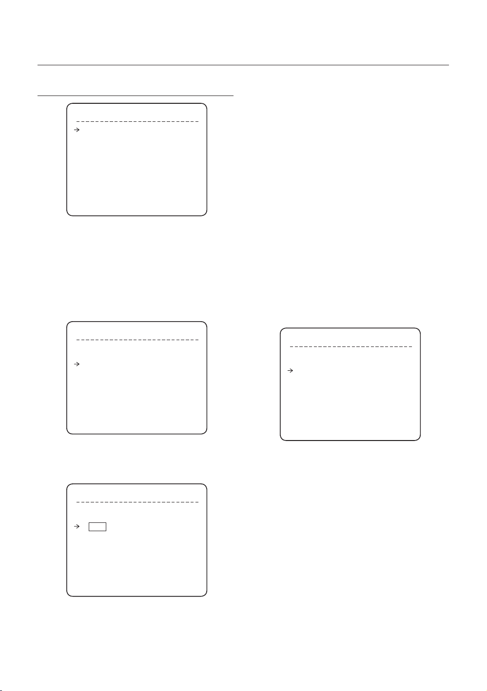
Jak korzystać z menu ekranowego
KONFIGURACJA HARMONOGRAMU
SCHEDULE SETUP
MASTER ENABLE ON
DAY TIME ACT NO ON
1 UNDEFINED
2 UNDEFINED
3 UNDEFINED
4 UNDEFINED
5 UNDEFINED
6 UNDEFINED
7 UNDEFINED
BACK
Master Enable [ON/OFF]
•
Zadecyduj, która funkcja harmonogramu ma być
włączona, a która nie.
Edit Schedule(Edycja harmonogramu)
❖
① Po przesunięciu kursora na wybrany numer przy
użyciu przycisków góra/dół naciśnij przycisk
„NEAR” (Enter), aby dokonać edycji.
SCHEDULE SETUP
MASTER ENABLE ON
DAY TIME ACT NO ON
1 UNDEFINED
2 UNDEFINED
3 UNDEFINED
4 UNDEFINED
5 UNDEFINED
6 UNDEFINED
7 UNDEFINED
BACK
Znaczenie każdej wartości:
DAY Days: MON TUE WED THU
FRI SAT SUN
WKD: dni robocze
Wszystkie dni (codziennie)
TIME Format 24-godzinny
ACT PRS(Preset), AUP(Auto Pan),
PTN(Pattern), SCN(Scan),
HOM(Home)
ON/OFF Zdecyduj, czy ta reguła ma zostać
włączona czy nie.
Po zakończeniu ustalania reguły, naciśnij
przycisk NEAR lub ENTER, aby wybrać
następną regułę.
Powtórz tę procedurę, aby wypełnić żądany
harmonogram.
③ Przykład
Druga reguła oznacza, że kamera będzie
–
przemieszczana do pozycji Preset 12 o 7.35
w każdą środę.
SCHEDULE SETUP
MASTER ENABLE ON
DAY TIME ACT NO ON
1 MON 01:20 HOM ON
2 WED 07:35 PRS 12 ON
3 THU 11:40 SCN 3 ON
4 SAT 15:17 PTN 1 ON
5 WKD 23:00 HOM ON
6 UNDEFINED
7 UNDEFINED
BACK
② Wybierać pola można za pomocą przycisków
w lewo/w prawo, a zmieniać wartości w polach
przy użyciu przycisków w górę/w dół.
* Uwaga: Jeśli reguły się nawzajem wykluczają,
ważniejsza jest ta, która ma wyższy numer.
* Uwaga: Przypisanie funkcji nieokreślonej nie
SCHEDULE SETUP
spowoduje żadnej czynności.
* Wskazówka: Przy użyciu zarezerwowanych
MASTER ENABLE ON
DAY TIME ACT NO ON
1 MON 00:00 HOM OFF
2 UNDEFINED
3 UNDEFINED
4 UNDEFINED
5 UNDEFINED
6 UNDEFINED
7 UNDEFINED
BACK
26 –
INTELIGENTNA KAMERA KOPUŁKOWA Z 36-KROTNYM ZOOMEM OPTYCZNYM
ustawień wstępnych można utworzyć różne
harmonogramy. Na przykład, PRS179 i PRS178
są odpowiednio trybem dnia i nocy.
(Patrz lista zarezerwowanych ustawień wstępnych
(strona 15) w tej instrukcji obsługi).
Page 93

Jak korzystać z menu ekranowego
KONFIGURACJA KAMERY
Skonfi guruj ogólne funkcje modułu zoomu kamery.
ZOOM CAMERA SETUP
FOCUS MODE SEMIAUTO
DIGITAL ZOOM ON
IMAGE FLIP OFF
FLICKERLESS OFF
<WHITE BALANCE SETUP>
<AUTO EXPOSURE SETUP>
White Balance Setup(Konfi guracja
❖
balansu bieli)
WB SETUP - GLOBAL
WB MODE AUTO
RED ADJUST ---
BLUE ADJUST ---
BACK
EXIT
Focus Mode [AUTO/MANUAL/SEMIAUTO]
•
Konfi guruje moduł ostrości kamery.
SEMIAUTO Mode (Tryb SEMIAUTO)
Tryb ten zmienia automatycznie tryb ustawiania
ostrości z trybu ręcznego na automatyczny. Tryb
ręcznego ustawiania ostrości zostaje włączony w
trakcie zaprogramowanej czynności. Natomiast
tryb automatycznego ustawiania ostrości jest
włączany po rozpoczęciu obracania kamery.
W trybie ręcznych ustawień wstępnych dane
ostrości są zapamiętywane w każdym ustawieniu
wstępnym z góry, a kamera ustawia dane ostrości
odpowiednio do ustawień wstępnych po tym, jak
znajdzie się w zaprogramowanej lokalizacji.
Digital Zoom [ON/OFF]
•
Włącza lub wyłącza funkcję cyfrowego zoomu.
Jeśli funkcja jest wyłączona, włączona jest funkcja
optycznego zoomu. Funkcja zoomu zostaje
zatrzymana pod koniec powiększania optycznego
zoomu.
Image Flip [ON/OFF]
•
Wyświetla odwrócony obraz.
Flickerless [ON/OFF]
•
Wyłącza lub wyłącza funkcję obrazu bez migotania.
W tej funkcji tryb AE staje się trybem preselekcji
migawki, a wartość szybkości migawki jest
ustawiona na 1/100 s.
BACK
EXIT
WB Mode [AUTO/MANUAL]
•
W trybie ręcznym poziom czerwieni i barwy
niebieskiej można ustawić ręcznie
Red Adjust [0~255]
•
Blue Adjust [0~255]
•
Auto Exposure Setup(Konfi guracja
❖
automatycznej ekspozycji)
AE SETUP
WDR/BLC ALL OFF
DAY/NIGHT AUTO
AE MODE AUTO
IRIS LEVEL ---
GAIN LEVEL ---
SHUTTER SPD ---
BRIGHTNESS ---
BACK
EXIT
WDR/BLC [ ALL OFF / WDR ON / BLC ON ]
•
Wybierz funkcję WDR (Szeroki zakres dynamiki) lub
BLC (Kompensacja oświetlenia tylnego). All OFF
oznacza wyłączenie obydwu funkcji.
Day/Night [AUTO/DAY/NIGHT]
•
AUTO exchanges Day / Night
AE MODE AUTO / MANUAL / IRIS / SHUTTER
•
/ BRIGHT
AUTO: Całkowicie automatyczny tryb funkcji AE
MANUAL: W trybie ręcznym Można zmienić funkcje
IRIS, GAIN, SHUTTER SPEED.
IRIS: Tryb preselekcji Iris. Można zmieniać tryb IRIS,
jednak inne są regulowane automatycznie.
SHUTTER: Tryb preselekcji migawki. Szybkość
migawki można zmienić, jednak inne funkcje są
regulowane automatycznie.
BRIGHT: W tym trybie można przypisać wartość
jasności AE.
POL
Polski – 27
Page 94

Jak korzystać z menu ekranowego
IRIS
•
[Działa, jeśli opcja AE MODE jest ustawiona na
MANUAL lub jeśli aktywny jest model IRIS]
Zakres: CLOSE/F1.6/F2/F2.4/F2.8/F3.4/F4/F4.8/
F5.6/F6.8/F8/ F9.6/F11/F14/F16/F19/F22/F28.
(18 kroków)
•
GAIN
[Działa, jeśli opcja AE MODE jest ustawiona na
MANUAL]
Automatycznie ulepsza jasność obrazu, gdy poziom
jasności obrazu jest zbyt niski.
Range: -3/0/2/4/6/8/10/12/14/16/18/20/22/24/26/
28dB (16 kroków)
•
Shutter Speed(Szybkość migawki)
[Działa, jeśli opcja AE MODE jest ustawiona na
MANUAL lub w trybie SHUTTER]
X64, X32, X16, X8, X4, X2,1/60,1/90,1/100,1/125,1/
180,1/250,1/350,1/500,1/725,1/1000,1/1500,1/
2000,1/4000,1/6000,1/10000
•
Brightness (Jasność)
[Działa, jeśli opcja AE MODE jest ustawiona na BRIGHT]
Reguluje jasność obrazów. Iris, Shutter Speed oraz
Gain są regulowane automatycznie równocześnie z
tą wartością. Zakres: 0-31 (32 kroki)
KONFIGURACJA SYSTEMU
SYSTEM SETUP
<DATE/TIME SETUP>
<RELAY TYPE>
<PASSWORD>
<SET HOME POSITION>
<SET NORTH DIRECTION>
LANGUAGE ENGLISH
•
•
Należy pamiętać, że zakres ustawień danych jest
DATE/TIME SETUP
DATE 01/JAN/2008(TUE)
TIME 00:00:01(H/M/S)
BACK
EXIT
Time (Godzina)
Godzina wyświetlana jest w formacie HH:MM:SS.
Date/Time Setup (Ustawianie daty/godziny)
Wybierać pola można za pomocą przycisków NEAR
lub ENTER, a zmieniać wartości w polach przy
użyciu przycisków góra/dół. Aby zapisać zmienione
dane, naciśnij przycisk NEAR lub ENTER.
ograniczony od 1 stycznia 2000 r. do 31 grudnia
2037 r.
RELAY TYPE SETUP
RELAY1 NORMAL OPEN
RELAY2 NORMAL OPEN
RELAY3 NORMAL OPEN
RELAY4 NORMAL CLOSE
BACK
EXIT
•
BACK
EXIT
Relay Type Setup (Ustawianie typu przekaźnika)
Określone są typy styków 4 kanałów WYJŚĆ
PRZEKAŹNIKOWYCH. (NORMAL OPEN / NORMAL
•
System Setup
Można skonfi gurować DATE/TIME, RELAY TYPE,
PASSWORD, HOME POSITION, NORTH POSITION.
•
Date
CLOSE)
NORMAL OPEN
NORMAL CLOSE
Data wyświetlana jest w formacie dd/mm/rrrr. Dzień
jest obliczany automatycznie po ustawieniu daty.
28 –
INTELIGENTNA KAMERA KOPUŁKOWA Z 36-KROTNYM ZOOMEM OPTYCZNYM
Page 95

Jak korzystać z menu ekranowego
EDIT PASSWORD
[█ ]
--------- 1234567890 OK
ABCDEFGHIJ CANCEL
KLMNOPQRST
UVWXYZabcd DISABLE
efghijklmn
opqrstuvwx
yz<>-/:.
----------
Password Setup (Ustawianie hasła)
•
Można zdefi niować hasło o długości 4 znaków.
Jeśli funkcja ta ustawiona jest na opcję ENABLE,
wprowadzenie tego hasła jest wymagane przy
każdym wchodzeniu do menu ekranowego.
Należy pamiętać, że MASTER PASSWORD to: „4321”
SET HOME POSITION
MOVE TO TARGET POSITION
[NEAR:SAVE / FAR:CANCEL]
•
Set Home Position (USTAWIANIE POZYCJI HOME)
0/0/x1/N
Pozycja HOME oznacza punkt początkowy kąta
PANORAMOWANIA. Na podstawie tej wyjściowej
pozycji obliczana jest wartość kąta PAN.
Przy użyciu joysticka przemieść kamerę do żądanej
pozycji i naciśnij ENTER (NEAR/SAVE).
Należy pamiętać, że pozycja wyjściowa nie ma
odniesienia do wartości kąta odchylenia.
W przypadku zmienienia położenia ustawienia
Home position wszystkie poziome ustawienia
funkcji takich jak ustawienie wstępne, schemat,
skanowanie, automatyczne skanowanie i maska
strefy prywatności zostaną przesunięte zgodnie ze
zmienionym ustawieniem Home position.
Jeśli nie zostały wybrane ustawienia funkcji takich
jak Preset, Pattern, Auto Pan i Scan, kamera
automatycznie ustawia się w położeniu Home po
ponownym uruchomieniu.
Jeśli funkcja Power Up Action ustawiona jest na
ON (WŁ.), kamera kontynuuje wykonywanie funkcji,
wykonywanej ostatnio po ponownym uruchamianiu.
* Ustawianie pozycji Home
W przypadku wymiany bloku kamery lub
zmiany jej orientacji w związku z czynnościami
konserwacyjnymi trudno jest utrzymać tę samą
orientację panoramowania. Z tego względu
wszystkie dane funkcji zależne od orientacji
panoramowania np. ustawienia wstępne,
schemat, skanowanie, automatyczne skanowanie
lub maska strefy prywatności tracą użyteczność.
Nawet w takim przypadku można jednak
wykorzystać dane w przypadku przedefi niowania
ustawienia pozycji Home do poprzedniego
położenia Home. Zaleca się zapamiętanie
docelowej sceny bieżącego położenia Home.
SET NORTH DIRECTION
MOVE TO TARGET POSITION
[NEAR:SAVE / FAR:CANCEL]
•
SET NORTH DIRECTION (USTAWIANIE KIERUNKU
0/0/x1/N
PÓŁNOCNEGO_
Można ustawić kierunek północny.
Przy użyciu joysticka przemieść kamerę do żądanej
pozycji PÓŁNOCNEJ i naciśnij ENTER (NEAR/SAVE).
Kierunek zostanie wyświetlony na ekranie
[PAN AXIS / TILT AXIS / ZOOM / DD]
DD oznacza kierunek i zostanie wyświetlone z:
N/NE/E/SE/S/SW/W/NW
•
Language (Język)
Można wybrać preferowany język w menu
ekranowym spośród 7 opcji.
[ENGLISH/ ESPAÑOL/ FRANÇAIS/ DEUTSCH/
ITALIANO/ РУССКИЙ/ PORTUGUÊS]
Po wybraniu języka naciśnij przycisk Enter (NEAR).
POL
Polski – 29
Page 96

Jak korzystać z menu ekranowego
INICJALIZACJA SYSTEMU
Konfi guracja ruchu
•
SYSTEM INITIALIZE
CLEAR ALL DATA NO
CLR DISPLAY SET NO
CLR CAMERA SET NO
CLR MOTION SET NO
CLR FUNCTION SET NO
REBOOT CAMERA NO
REBOOT SYSTEM NO
BACK
EXIT
Clear All Data
•
Usuwa wszystkie dane konfi guracji, takie jak
ustawienia wyświetlacza, kamery, ruchu itd.
Clear Display Set
•
Przywraca konfi gurację wyświetlacza do ustawień
domyślnych
Clear Camera Set
•
Przywraca konfi gurację kamery do ustawień
wstępnych
•
Clear Motion Set
Przywraca konfi gurację ruchu do ustawień
wstępnych
Clear Function Set
•
Usuwa dane ustawień wstępnych, autopanoramowania,
schematów, skanowania i harmonogramu
•
Reboot Camera
Wyłącza i włącza ponownie moduł zoomu kamery
Reboot System
•
Wyłącza i włącza ponownie Kamera kopułowa
SmartDome
Preset Lock OFF
Power Up Action ON
Auto Flip ON
Jog Max Speed 140°/sec
Jog Direction NORMAL
Freeze In Preset OFF
Park Action OFF
Alarm I/O Action OFF
Konfi guracja komunikacji
•
Protocol AUTO
Baud Rate 9600
Konfi guracja kamery
•
Focus Mode SEMIAUTO
Digital Zoom ON
Image Flip ON
Flickerless OFF
White Balance AUTO
Backlight/BLC ALL OFF
Day/Night AUTO
AE Mode AUTO
Iris Level F4
Gain Level +2dB
Shutter Speed 1/60
Brightness 13
Tabela konfi guracji początkowej
❖
Konfi guracja wyświetlacza
•
Camera ID ON
PTZ Information AUTO
Action Title AUTO
Preset Label AUTO
Alarm I/O AUTO
Date/Time ON
Privacy Zone Undefi ned
30 –
INTELIGENTNA KAMERA KOPUŁKOWA Z 36-KROTNYM ZOOMEM OPTYCZNYM
Function Data
•
Preset 1~128 Undefi ned
Auto Pan 1~8 Undefi ned
Pattern 1~4 Undefi ned
Scan 1~8 Undefi ned
Schedule 1~7 Undefi ned
Page 97

DANE TECHNICZNE
Pozycja Informacje
SCC-C7478N : System kolorów standardowych NTSC
SCC-C7478P : System kolorów standardowych PAL
Oświetlenie Nasycenie Kolor
50 IRE Nie 1.40 lx 0.15000 lx
30 IRE Nie 0.84 lx 0.09000 lx
15 IRE Nie 0.42 lx 0.04500 lx
50 IRE 64 razy 0.0219 lx 0.00230 lx
30 IRE 64 razy 0.0131 lx 0.00140 lx
15 IRE 64 razy 0.0066 lx 0.00070 lx
Autom./ręczny (regulowane wzmocnienie czerwieni, niebieskiego)
Ustawienie wstępne
Manual :
Autopanoramowanie:
127 ustawień wstępnych (etykieta, ustawienie obrazu kamery)
Obsługa 7 języków : [ENGLISH /ESPAÑOL /FRANÇAIS
(z uchwytem mocującym)
Typ przymocowywany na ścianie : Około 6 kgf (13.2 funtów)
Typ mocowany na sufi cie : Około 5.8 Kgf (12.8 funtów)
Kamera
Panoram.
/odchyl.
Ogólne
Typ nadawania
CCD EX-View HAD CCD
Efektywna liczba
pikseli
Rozdzielczość pozioma
Współczynnik sygnał/szum
Zoom 36-krotny zoom optyczny, 12-krotny zoom cyfrowy
Odległość ogniskowa f=3,4 mm (szeroki kat) – 122,4 mm (tele), F1,6–F4,5
Min. oświetlenie
Wyjście sygnału
Dzień/noc Autom./dzień/noc (ICR)
Ostrość Autom./ręczna/pół-autom.
Iris Autom./ręczne
Szybkość migawki X64 ~ X2, 1/60 ~ 1/10,000s
AGC Autom./ręczna (-3 – 28dB)
Balans bieli
WDR, BLC WDR wł./wył., BLC wł./wył.
Bez migotania Możliwość wyboru
Strefa prywatności 8 obszar
Zakres
Prędkość panoram./
odchyl.
Ustawienie wstępne
Schemat 4 schematy, 1000 poleceń (około 5 Minut)/schemat
Autopanoramowanie 8 autopan
Skanowanie 8 skanów (20 obiektów czynności/skan)
Inne funkcje Funkcje: Auto Flip, Auto Parking, Power Up Action itd.
Komunikacja RS-485
Protokół Możliwość wyboru: Auto, Pelco-D, Pelco-P, Samsung
Strefa prywatności 8 stref
Wejście alarmu 8 wejść
Wyjście alarmu 4 wyjścia przekaźnikowe
Informacje ekranowe
Gniazdo zasilania
Pobór mocy
Wymiary
Ciężar
Temp. eksploatacji -45°C - 50°C (-49°F - 122°F)
Żywotność głównych części
Dane techniczne
❖
•
SCC-C7478N : 768(H) × 494(V)
SCC-C7478P : 752(H) × 582(V)
Kolor: 540 / BW : Przewód TV 570
Około 50 dB
Czarno-białe (oprogr.)
Wyjście zespolonego sygnału wideo:
1,0 Vp-p, 75 omów/BNC
•
Panoram : 360°(nieograniczone)
Odchyl : 180°
: 360°/s
Ręcznie: 0,05–200°/s (Odwrotnie proporcjonalnie do Zoom.
1 ~ 180°/sec
Menu/informacje o PTZ itd.
/DEUTSCH/ITALIANO /РУССКИЙ /PORTUGUÊS]
SCC-C7478N : AC 24V ± 10% (60Hz ± 0,3Hz)
SCC-C7478P : AC 24V ± 10% (50Hz ± 0,3Hz)
24 W (nagrzewnica wył.)/57 W (nagrzewnica wł.)
Kamera
(tylko kamera)
Kamera
Pierścień ślizgowy: 10 000 000 obrotów
(Ø × W) : 259 × 265.7 mm
: 10.2 × 10.46 cali
Typ przymocowywany
na ścianie
(SZ X W X G)
Typ mocowany na
sufi cie (Ø X W)
:
259X404.5X 551.7 mm
:10.2X15.9X21.7 cali
: 259X648.7 mm
: 10.2X25.54 cali
)
Dane techniczne tego produktu mogą ulec
zmianie bez powiadomienia.
Wygląd
Montowana na ścianie
Przystawka sufi towa
Należy uważnie sprawdzić napięcie i
natężenie prądu dla mocy znamionowej.
Polski – 31
POL
Page 98

Dane techniczne
WYMIARY
Uchwyt ścienny
•
Urządzenie (mm)
GWINT RURY
Przystawka sufi towa
•
GWINT RURY
GWINT RURY
32 –
INTELIGENTNA KAMERA KOPUŁKOWA Z 36-KROTNYM ZOOMEM OPTYCZNYM
Page 99

Prawidłowe usuwanie produktu (zużyty sprzęt elektryczny i elektroniczny)
Oznaczenie umieszczone na produkcie lub w odnoszących się do niego tekstach wskazuje, że produktu po upływie
okresu użytkowania nie należy usuwać z innymi odpadami pochodzącymi z gospodarstw domowych. Aby uniknąć
szkodliwego wpływu na środowisko naturalne i zdrowie ludzi wskutek niekontrolowanego usuwania odpadów,
prosimy o oddzielenie produktu od innego typu odpadów oraz odpowiedzialny recykling w celu promowania
ponownego użycia zasobów materialnych jako stałej praktyki.
W celu uzyskania informacji na temat miejsca i sposobu bezpiecznego dla środowiska recyklingu tego produktu
użytkownicy w gospodarstwach domowych powinni skontaktować się z punktem sprzedaży detalicznej, w którym
dokonali zakupu produktu, lub z organem władz lokalnych.
Użytkownicy w firmach powinni skontaktować się ze swoim dostawcą i sprawdzić warunki umowy zakupu. Produktu
nie należy usuwać razem z innymi odpadami komercyjnymi.
Page 100

SCC-C7478
36x Smart Dome Kamera
Kullanım Kılavuzu
olasılıkları hayal edin
Bu Samsung ürününü aldığınız için teşekkürler.
Daha ayrıntılı bir hizmet için, lütfen şu web adresinde ürün
kaydınızı yapın:
www.samsung.com/global/register
TUR
 Loading...