


SCC-C7478
36x Smart Dome Camera
User’s Guide
ENG FRC
imagine the possibilities
Thank you for purchasing this Samsung product.
To receive more complete service,
please register your product at
www.samsung.com/global/register
SPA-M POR-B
JAP
Safety information
CAUTION
RISK OF ELECTRIC SHOCK.
DO NOT OPEN
CAUTION: TO REDUCE THE RISK OF ELECTRIC SHOCK, DO NOT REMOVE COVER (OR BACK) NO USER SERVICEABLE PARTS
INSIDE. REFER SERVICING TO QUALIFIED SERVICE PERSONNEL.
This symbol indicates that dangerous voltage consisting a risk of electric shock is present
within this unit.
This exclamation point symbol is intended to alert the user to the presence of important
operating and maintenance (servicing) instructions in the literature accompanying the
appliance.
WARNING
To reduce the risk of fi re or electric shock, do not expose this appliance to rain or moisture.
•
To prevent injury, this apparatus must be securely attached to the fl oor/wall in accordance with the installation
•
instructions.
If this power supply is used at 240V ac, a suitable plug adapter should be used.
•
WARNING
1.
Be sure to use only the standard adapter that is specifi ed in the specifi cation sheet.
Using any other adapter could cause fi re, electrical shock, or damage to the product.
2.
Incorrectly connecting the power supply or replacing battery may cause explosion, fi re, electric shock, or damage
to the product.
3.
Do not connect multiple cameras to a single adapter. Exceeding the capacity may cause abnormal heat
generation or fi re.
4.
Securely plug the power cord into the power receptacle. Insecure connection may cause fi re.
5.
When installing the camera, fasten it securely and fi rmly. The fall of camera may cause personal injury.
6.
Do not place conductive objects (e.g. screwdrivers, coins, metal parts, etc.) or containers fi lled with water on top
of the camera. Doing so may cause personal injury due to fi re, electric shock, or falling objects.
7.
Do not install the unit in humid, dusty, or sooty locations. Doing so may cause fi re or electric shock.
8.
If any unusual smells or smoke come from the unit, stop using the product. In such case, immediately disconnect
the power source and contact the service center. Continued use in such a condition may cause fi re or electric
shock.
9.
If this product fails to operate normally, contact the nearest service center. Never disassemble or modify this product
in any way. (SAMSUNG is not liable for problems caused by unauthorized modifi cations or attempted repair.)
10.
When cleaning, do not spray water directly onto parts of the product. Doing so may cause fi re or electric shock
If the camera is installed or rebooted after power failure when ambient temperature is below the freezing point, the
11.
dome cover is frosted. In this case, the frost will be disappeared after 3 hours after turning on the power.
(It is noted that lowest guaranteed operating temperature is -45ºC(-49ºF) without wind.).
2 – 36x SMART DOME CAMERA

Safety information
CAUTION
Do not drop objects on the product or apply strong blows to it. Keep away from a location subject to excessive
1.
vibration or magnetic interference.
Do not install in a location subject to high temperature (over 140°F), low temperature (below -49°F), or high
2.
humidity. Doing so may cause fi re or electric shock.
If you want to relocate the already installed product, be sure to turn off the power and then move or reinstall it.
3.
Remove the power plug from the outlet when there is a lighting storm. Neglecting to do so may cause fi re or
4.
damage to the product.
Keep out of direct sunlight and heat radiation sources. It may cause fi re.
5.
Install it in a place with good ventilation.
6.
Avoid aiming the camera directly towards extremely bright objects such as sun, as this may damage the CCD
7.
image sensor.
8.
Apparatus shall not be exposed to dripping or splashing and no objects fi lled with liquids, such as vases, shall be
placed on the apparatus.
The Mains plug is used as a disconnect device and shall stay readily operable at any time.
9.
FCC Statement
This device complies with part 15 of the FCC Rules. Operation is subject to the following two conditions :
1) This device may not cause harmful interference, and
2) This device must accept any interference received including interference that may cause undesired operation.
ENG
Caution
This equipment has been tested and found to comply with the limits for a Class A digital device, pursuant to part 15 of FCC Rules. These limits are designed to provide reasonable protection against harmful
interference when the equipment is operated in a commercial environment.
This equipment generates, uses, and can radiate radio frequency energy and, if not installed and used
in accordance with the instruction manual, may cause harmful interference to radio communications.
Operation of this equipment in a residential area is likely to cause harmful interference in which case the
user will be required to correct the interference at his own expense.
IC Compliance Notice
This Class A digital apparatus meets all requirements of the Canadian Interference.-Causing
Equipment Regulations of ICES-003.
English – 3

Important Safety Instructions
Read these instructions.
1.
Keep these instructions.
2.
Heed all warnings.
3.
Follow all instructions.
4.
Do not use this apparatus near water.
5.
Clean only with dry cloth.
6.
Do not block any ventilation openings. Install in accordance with the manufacturer’s instructions.
7.
Do not install near any heat sources such as radiators, heat registers, or other apparatus (including amplifi ers) that
8.
produce heat.
Do not defeat the safety purpose of the polarized or grounding-type plug. A polarized plug has two blades with
9.
one wider than the other. A grounding type plug has two blades and a third grounding prong. The wide blade or
the third prong is provided for your safety. If the provided plug does not fi t into your outlet, consult an electrician
for replacement of the obsolete outlet.
Protect the power cord from being walked on or pinched particularly at plugs, convenience receptacles, and the
10.
point where they exit from the apparatus.
Only use attachments/accessories specifi ed by the manufacturer.
11.
Use only with cart, stand, tripod, bracket, or table specifi ed by the manufacturer, or sold
12.
with the apparatus.
Unplug this apparatus when a card is used. Use caution when moving the cart/ apparatus
13.
combination to avoid injury from tip-over.
Refer all servicing to qualifi ed service personnel. Servicing is required when the apparatus
14.
has been damaged in any way, such as powersupply cord or plug is damaged, liquid has been spilled or objects
have fallen into the apparatus, the apparatus has been exposed to rain or moisture, does not operate normally, or
has been dropped.
Apparatus shall not be exposed to dripping or splashing and no objects fi lled with
liquids, such as vases, shall be placed on the apparatus
4 – 36x SMART DOME CAMERA

Contents
Introduction
Features 6
Product & Accessories 7
Parts Name & Functions 8
Installation
DIP Switch Setup 9
Installation using Mount Bracket 10
Cabling 13
Operation
Check points before operation 15
Preset and Pattern Function Pre-Check 15
AUTO CALIBRATION 15
Starting OSD Menu 15
Reserved Preset 15
Preset 16
Auto Pan 16
Pattern 16
Scan 16
Schedule 17
Other Functions 17
OSD Display of Main Screen 18
General Rules of Key Operation for Menu 18
ENG
How to use OSD Menu
Main Menu 19
System Information 19
Display Setup 19
PRIVACY ZONE MASK Setup 19
Motion Setup 20
Function Setup 21
PRESET Setup 22
Auto Pan Setup 23
Pattern Setup 23
Scan Setup 24
Schedule Setup 26
CAMERA SETUP 27
System Setup 28
System Initialize 30
Specifi cations
Specifi cations 31
Dimension 32
English – 5

Introduction
FEATURES
Camera Specifi cations
❖
CCD Sensor : EX-view HADTM CCD
•
Zoom Magnifi cation : × 36 Optical Zoom, × 12
•
Digital Zoom (Max × 432 Zoom)
Wide Dynamic Range Function
•
Day & Night Function : ICR(IR Cut fi lter Removal)
•
Various Focus Mode : Auto Focus / Manual Focus
•
/ Semi-Auto Focus.
•
Independent or Global camera settings for each
Preset locations.
Powerful Pan/Tilt Functions
❖
•
Max. 360°/sec high speed Pan/Tilt Motion
•
Using Vector Drive Technology, Pan/Tilt motions
are accomplished in the shortest path. As a result,
time to target view is reduced dramatically and the
video on the monitor is very natural to watch.
•
Ultra low speed (0.05°/sec) enables operator
to locate camera to desired target view with
accuracy and ease.
•
Zoom-proportional pan/tilt speed helps operator
to move the camera easily.
Preset, Pattern, Auto Pan, Scan, Privacy
❖
Mask, Schedule and More…
MAX. 127 Presets are assignable. All of them
•
have independent characteristics such as White
Balance, Auto Exposure, Label, Alarm Input/
Output and so on.
Max. 8 set of Auto Pan can be stored. This
•
enables to move camera repetitively between two
preset positions with designated speed.
Max. 4 of Patterns can be recorded and played
•
back. This enables to move camera to follow any
trajectory operated by joystick as closely as possible.
Max. 8 set of Scan action can be stored.
•
This enables to move camera repetitively with
combination of Preset or Pattern or Auto Pan. A
Scan is composed of max. 20 entities of Preset/
Pattern/Auto Pans.
Max 8 Privacy Masks can be set up to protect
•
privacy of other people.
7 rules of Schedule can be assigned by day and
•
time. Appropriate actions (such as Home, Preset,
Scan, Pattern and Auto Pan) can be defi ned for
each rule. Also, it is possible to use Weekday and
All days to simplify the rule.
PTZ(Pan/Tilt/Zoom) Control
❖
With RS-485 communication, max. 255 of
•
cameras can be controlled at the same time.
•
Pelco-D/ Pelco-P/ Samsung protocol can be
selected as a control protocol in the current
version of fi rmware.
OSD(On Screen Display) Menu
❖
OSD menu is provided to display the status
•
of camera and to confi gure the functions
interactively.
The information such as Camera ID, Pan/Tilt/
•
Zoom/Direction, Alarm Input & Output, date/time,
current temperature and Preset can be displayed
on screen.
Each display item can be turned on or off
•
independently.
Alarm I/O Functions
❖
8 alarm sensor Inputs and 4 relay output are
•
available.
To reject external electric noise and shock
•
perfectly, alarm sensor Input is decoupled with
photo coupler.
The signal range of sensor input is from DC 5.0 to
•
12.0 volts to adopt various applications.
If an external sensor is activated, camera can be
•
set to move to the corresponding Preset position.
Relay outputs can be assigned to work with a
•
certain preset.
Reserved Presets for Special Purpose
❖
Most of camera settings are directly changed by
•
calling Reserved Presets, not entering into OSD
menu. For more information,refer to “Reserved
Presets”(page 15) in this manual.
6 – 36x SMART DOME CAMERA
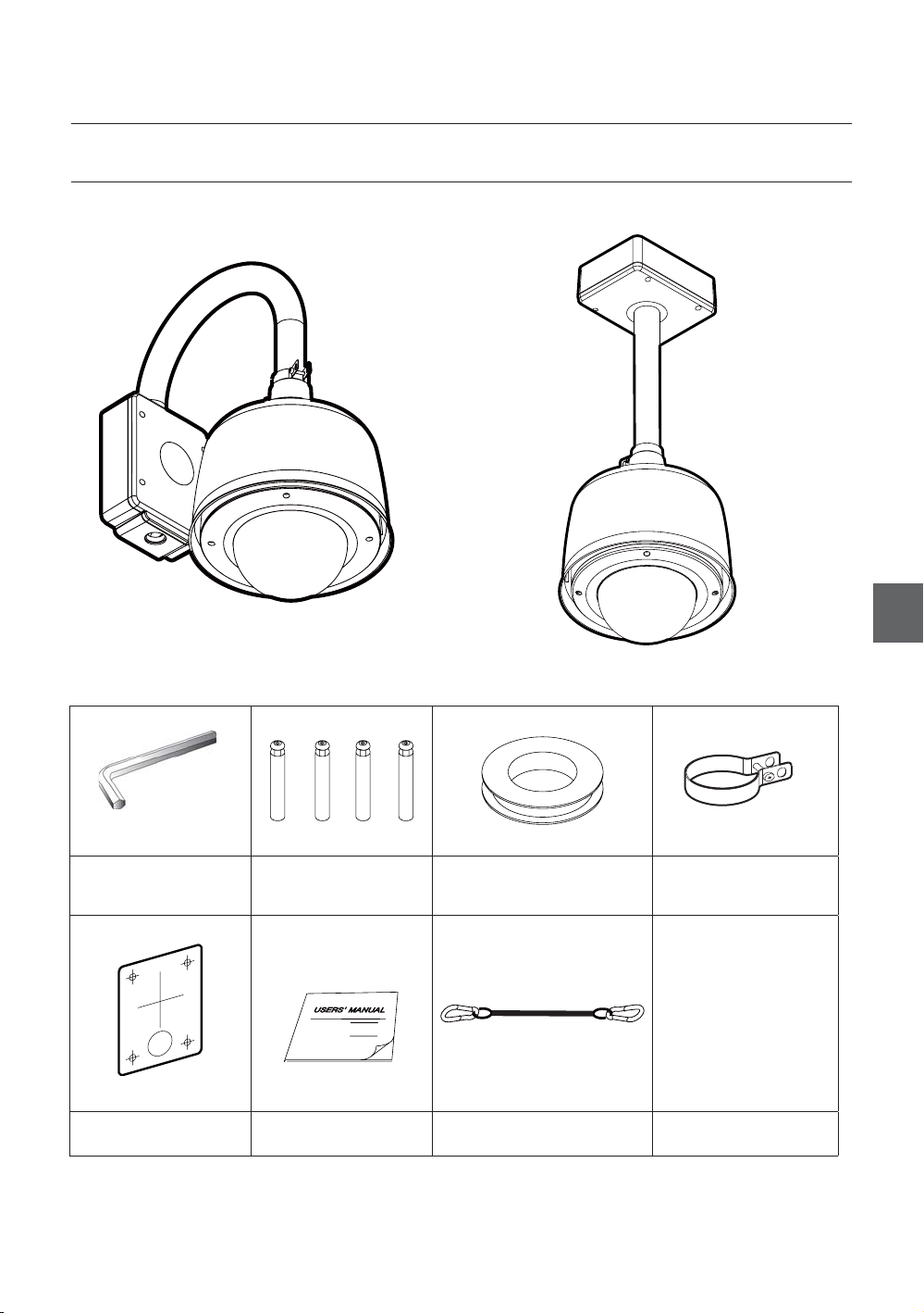
PRODUCT & ACCESSORIES
Product❖
Wall Mount Type Ceiling Mount Type
Accessories❖
Introduction
ENG
Hexagonal wrench Anchor bolts (4pcs) Water proof tape
Hole Template
User’s Guide Safety Cable
Housing Safety Cable
Hanger
English – 7
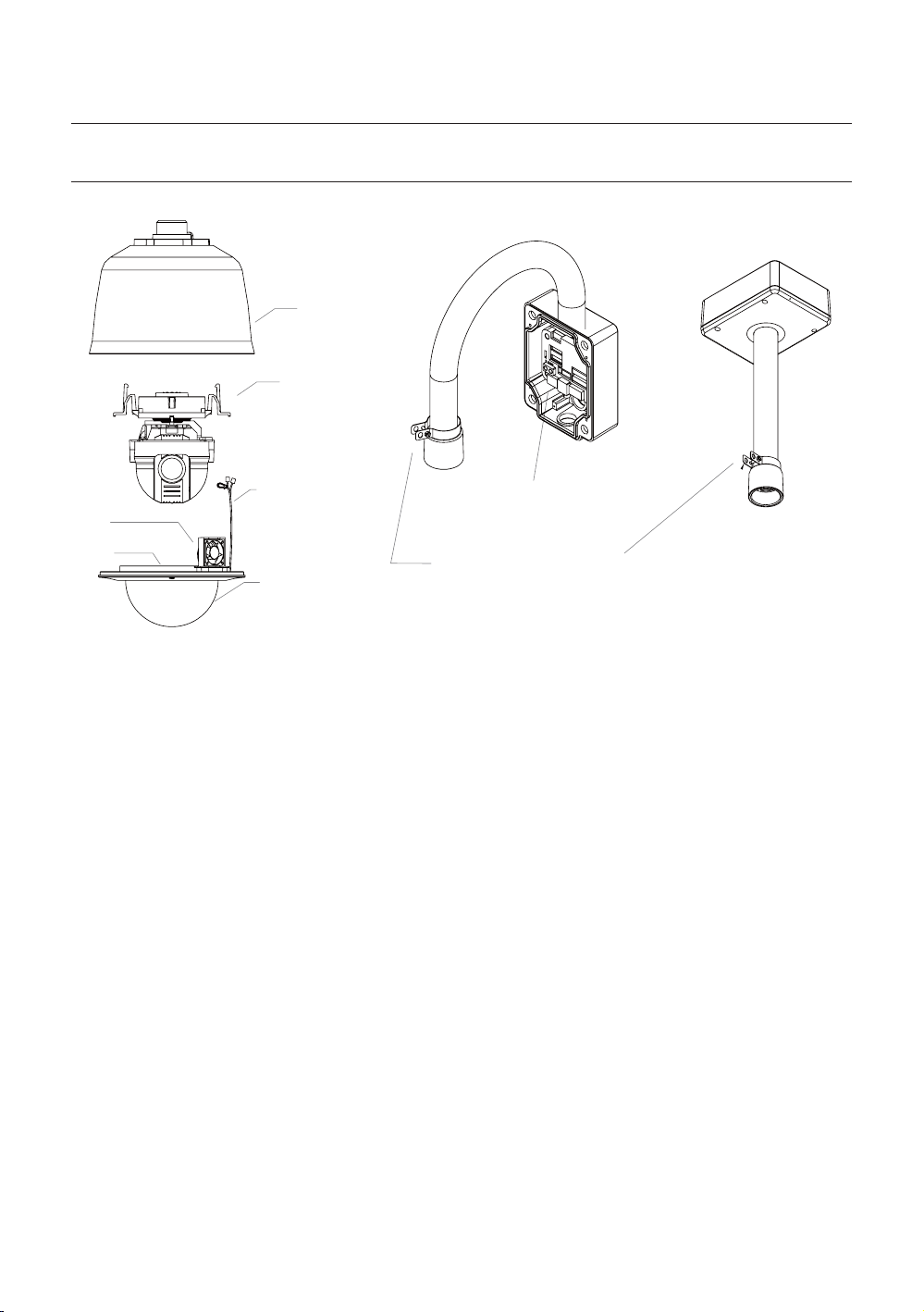
Introduction
PARTS NAME & FUNCTIONS
SUN SHIELD & UPPER
HOUSING
PTZ MECHANISM
DOME SAFETY CABLE
FAN
HEATER
Dome Cover
•
Do not detach protection vinyl from dome cover
before fi nishing all installation process to protect
dome cover from scratches or dust.
In the dome cover, there are Fan and Heater to
remove moisture on the bubble dome.
Sunshield & Upper housing
•
Sunshield protect bubble dome cover from the sun
rays and rain fall from. In the sunshield, there is the
upper housing which will contain accommodate
PTZ mechanism. Also, the upper housing will be
connected to both mounting brackets and dome
cover.
FAN & HEATER CABLE
DOME COVER
INNER BOX
HOUSING SAFETY CABLE HANGER
Wall/Ceiling mount Bracket
•
These are used to install the camera on the wall or
ceiling and have junction box. The junction box of the
bracket accommodate inner box.
Inner box
•
The inner has many important roles of connection
box between camera and outside. Top of the box,
there are dip switches and terminal blocks for Power
supply, Video, Communication, Alarm Input/output.
8 – 36x SMART DOME CAMERA
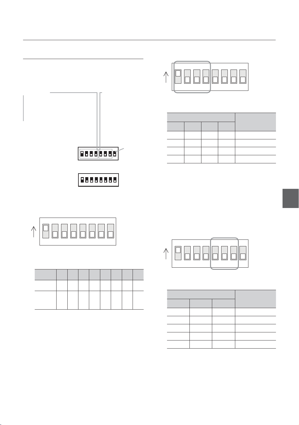
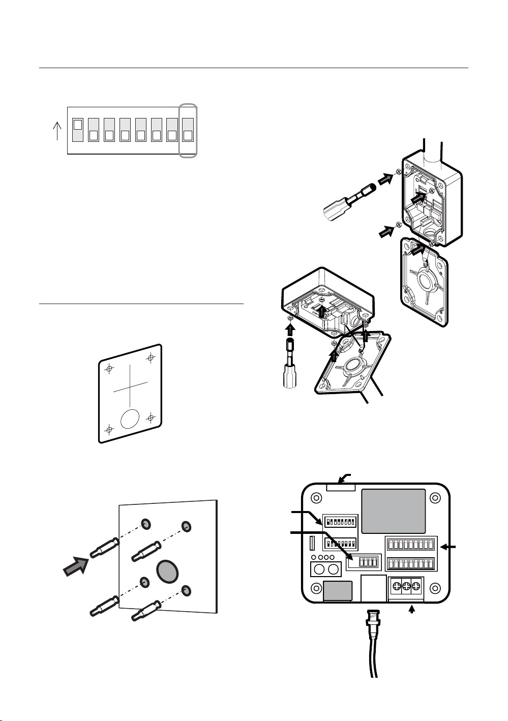
DIP SWITCH SETUP
Installation
❖
Communication Protocol Setup
Before you install the camera, you should set the DIP
switches to confi gure the camera ID, communication
protocol.
w
WWWGaGhGw
WWXGaGwTk
WWYGaGwTw
WWZGaGzhtz|un
Camera ID Setup
❖
ON
ON
pkGzGOX¥Y\\P
iGy
WWWGaGY[WW
WWXGaG[_WW
WWYGaG`]WW
WWZGaGX`YWW
WW[GaGZ_[WW
yzT[_\
{
ON
ON
123456
Select the appropriate Protocol with DIP switch
•
78
combination.
Switch State
Pin1 Pin2 Pin3 Pin4
OFF OFF OFF OFF Auto Protocol
ON OFF OFF OFF PELCO-D
OFF ON OFF OFF PELCO-P
ON ON OFF OFF SAMSUNG
If you set the protocol as Auto Protocol, camera will
•
Protocol
automatically recognize the kind of Protocol.
If you want to control using DVR or system keyboard,
•
their protocol must be identical to camera. Otherwise,
you can not control the camera.
If you changed camera protocol by changing DIP S/W,
•
the change will be effective after you reboot the camera.
Factory default of protocol is “Auto” Protocol
•
Communication Baud rate Setup
❖
ENG
123456
ID number of camera is set using binary number.
•
78
The example is shown bellow.
Pin 12345678
ID Value 1 2 4 8 16 32 64 128
ex) ID=5
ex) ID=10onoff
The range of ID is 0~255. Factory default of
•
offonon
off
offonoff
off
off
off
off
off
Camera ID is 1.
If you want to control a certain camera, you must
•
match the camera ID with Cam ID setting of DVR
or Controller.
off
off
ON
ON
123456
Select the appropriate Baud rate with DIP switch
•
78
combination.
Switch State
Pin5 Pin6 Pin7
OFF OFF OFF 2400 BPS
ON OFF OFF 4800 BPS
OFF ON OFF 9600 BPS
ON ON OFF 19200 BPS
OFF OFF ON 38400 BPS
•
Factory default of Baud rate is “9600 BPS”
Protocol
English – 9
Installation
A
RS-485 Termination Resistor
❖
ON
ON
123456
Pin 8 is used for ON/OFF of RS-485 Termination.
•
78
Normally, it must be OFF state. Especially when
you have trouble with long Daisy chain style
connection, turn ON this termination switch of last
camera.
Pin 8 RS-485 Termination Resistor (On/Off)
–
INSTALLATION USING MOUNT
BRACKET
① Using the paper template, mark the holes on the
wall.
③ After locating the wall mount bracket on the
anchor bolts properly. Tighten the nuts for
anchor bolts
④ Connect cables to terminal blocks and BNC in
the inner box of junction box. See the cabling in
② After drilling the holes, fi x the four anchor bolts
into the holes.
10 – 36x SMART DOME CAMERA
the next section.
Protocol,
Address DIP
RS-485
Connector to the dome camera
POWER
BNC
VIDEO
LARM
Installation
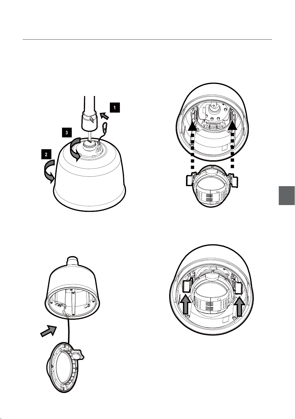
⑤ After hooking the safety cable on the hole of
pipe [1], attach the upper housing to wall mount
bracket by turning it at least seven turns [2]. To
fi x the upper body orientation, turn the handle of
double nuts to clockwise tightly [3].
Open the dome cover to install the PTZ camera
⑥
mechanism. Care must be taken dome cover is
hung by internal safety cable properly. Plug fan/
heater cables into the connectors in the housing.
⑦ Plug the connector of cable from junction box
into properly. After checking the orientation
of one touch connector in the upper housing,
press the PTZ mechanism into hook in the
upper housing.
ENG
⑧ To lock the PTZ mechanism to the upper
housing, press the two black handles till it
sounds snap.
G
English – 11
Installation
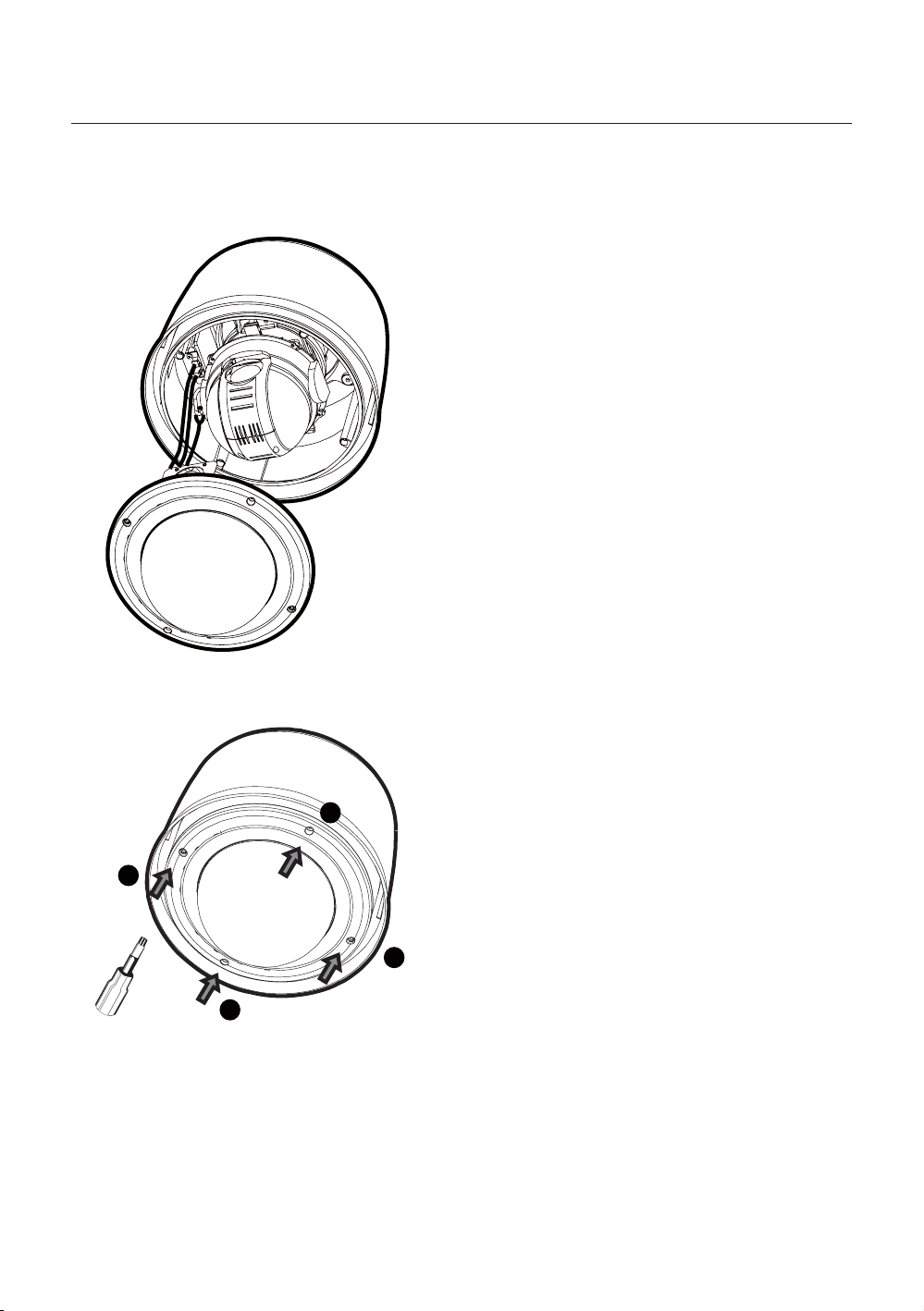
⑨ Close the dome cover. Care must be taken to
locate dome cover by matching the “Arrow”
mark.
ٻ
ٻ
ٻ
ٻ
ٻ
ٻ
⑩ Tighten four screws on the dome cover in
sequence as shown in the picture bellow.
ٻ
ٻ
ٻ
1
To maintain the best sealing, the torque of each
screw must be in the range between 0.5 ~ 1.0 N·m
(0.37 ~ 0.73 lbf·ft).
ٻ
ٻ
ٻ
3
4
2
12 – 36x SMART DOME CAMERA
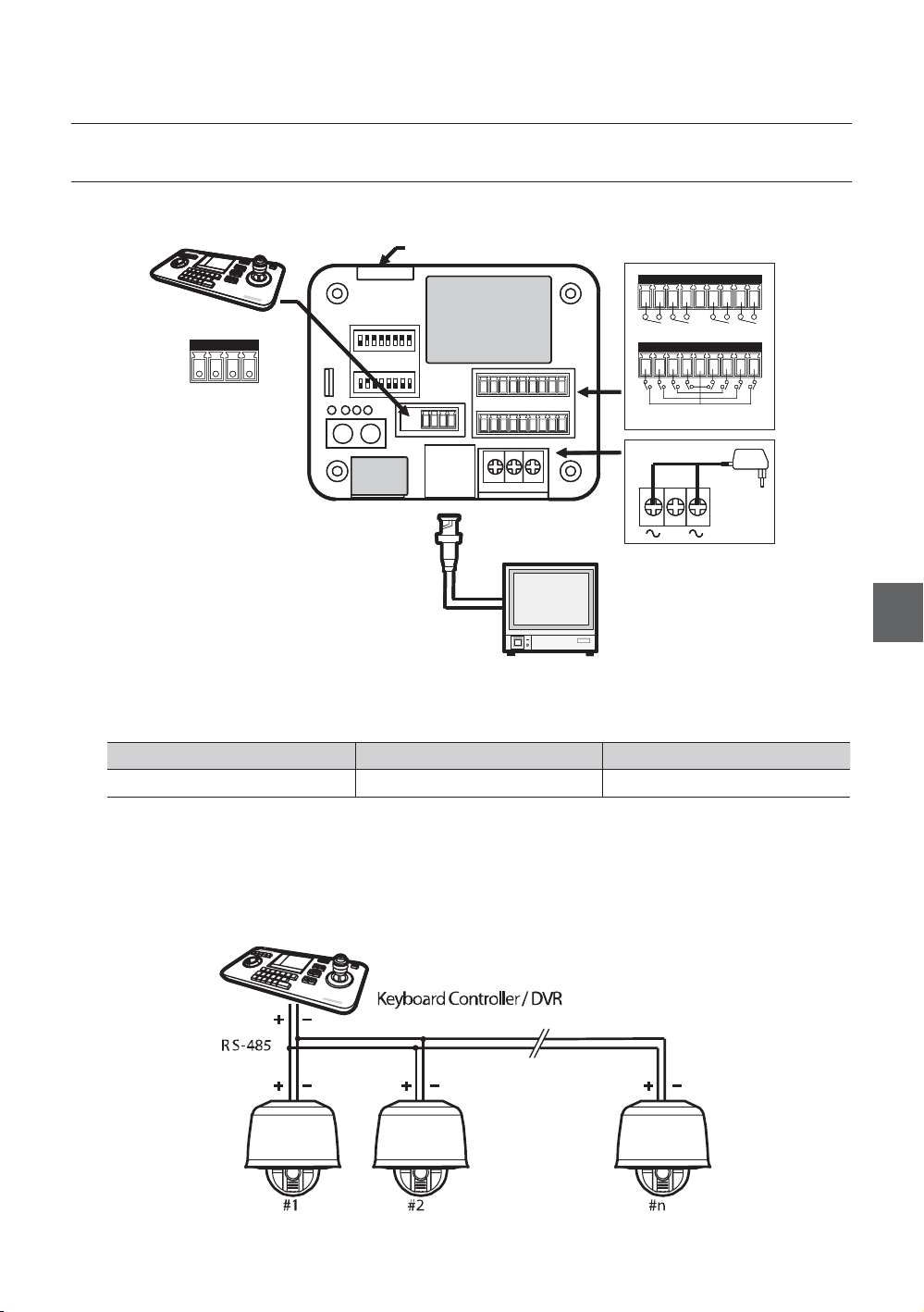
CABLING
DVR/ Keyboard
DVR/ Keyboard
DVR/ Keyboard
RS-485
RS-485
RS-485
D+ D- D+
D+ D- D
D+ D-D- D
Connector to the dome camera
Connector to the dome camera
BNC
BNC
VIDEO
VIDEO
Monitor
Monitor
Installation
ALARM OU TPUT
ALARM OU TPUT
ALARM OU TPUT
12 34
12 34
12 34
ALARM IN PUT
ALARM IN PUT
ALARM IN PUT
G1234 5678
G1234 5678
G1234 5678
POWER
POWER
POWER
NC.
NC.
NC.
ENG
Power Connection
❖
Please, check the voltage and current capacity of rated power carefully.
•
Rated Power Input Voltage Range Current Consumption
AC 24V AC 19V ~29V 2.5 A
RS-485 Communication
❖
For PTZ control, connect this line to keyboard and DVR. To control multiple cameras at the same time, RS-485
•
communication lines of them is connected in parallel as shown below.
English – 13
Installation
Video Connection
❖
Connect with BNC coaxial cable.
•
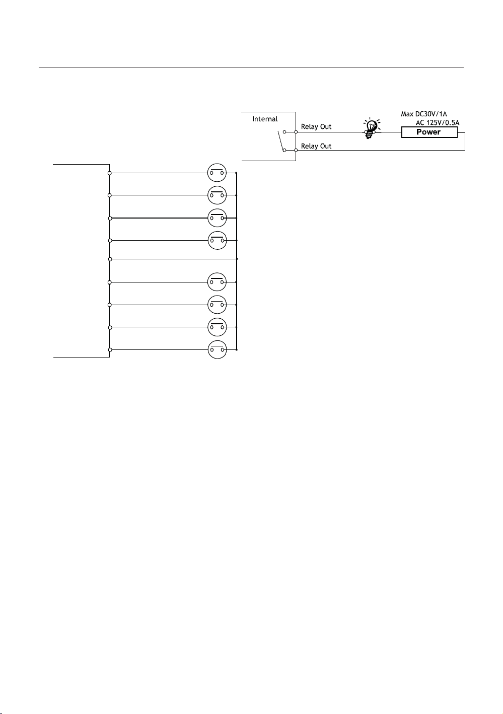
Alarm Output
•
Alarm Input Connection
❖
Sensor Input
•
IN 1
INTERNAL
IN 2
IN 3
IN 4
GND
IN 5
IN 6
IN 7
IN 8
a It is noted that short circuit between GND and
Input pin means alarm activation.
There are 4 Alarm Outputs and all of them are
Relay contact type. Therefore, you do not have
to care about polarity, AC/DC, and isolations
between channels. Care must be taken for the
power capacity of relay contact written above.
If you want to use Alarm Input, the types of sensor
must be selected in OSD menu. The sensor types
are Normal Open and Normal Close If sensor type
is not selected properly, the alarm can be activated
reversely.
14 – 36x SMART DOME CAMERA

Operation
CHECK POINTS BEFORE
OPERATION
Before power is applied, please check the cables
•
carefully.
The camera ID of the controller must be identical to
•
that of the camera to be controlled. The camera ID
can be checked in the System Information of OSD
Menu.
If your controller supports multi-protocols, the
•
protocol must be changed to match to that of the
camera.
If you changed camera protocol by changing DIP
•
switch, the change will be effective after you reboot
the camera.
Since the operation method can be different for
•
each controller available, refer to the manual for your
controller if camera can not be controlled properly.
PRESET AND PATTERN
FUNCTION PRE-CHECK
•
Check how to operate Preset, Scan, Auto Pan and
Pattern function with controller or DVR in advance to
operate camera function using them. (refer to your
System keyboard Manual)
•
If controller or DVR has no pattern button or function,
use shortcut keys with preset numbers. For more
information, refer to “Reserved Preset” in this
manual.
AUTO CALIBRATION
•
If the camera is continuously subjected to very high
temperature (over 50°C or 122°F) environment for a
long time, it is possible for the camera to lose focus.
As a result, you will get blurry image. In this case, it is
recommended to turn on “AUTO CALIBRATION” by
running Preset 165.
•
If you execute AUTO CALIBRATION, camera will
calibrate its focus at every 6 hours. To turn off this
function, please, run Preset 166.
STARTING OSD MENU
Function
•
Using the OSD menu, Preset, Pattern, Auto Pan,
Scan and Alarm Input function can be confi gured for
each application.
Enter Menu
•
<Go Preset> [95]
RESERVED PRESET
Description
•
Some Preset numbers are reserved to special
functions.
Function
•
<Go Preset> [95] : Enters into OSD menu
<Go Preset> [131~134] : Runs Pattern Function 1~4
<Go Preset> [141~148] : Runs Auto Pan Function 1~8
<Go Preset> [151~158] : Runs Scan Function 1~8
<Go Preset> [161~164] : Sets Relay 1~4 Output to OFF
<Set Preset> [161~164] : Sets Relay 1~4 Output to ON
<Go Preset> [170] : Sets Camera BLC Mode to OFF
<Go Preset> [171] : Sets Camera BLC Mode to HIGH
<Go Preset> [174] : Sets Camera Focus Mode to AUTO
<Go Preset> [175] : Sets Camera Focus Mode to Manual
<Go Preset> [176] : Sets Camera Focus Mode to SEMI-
AUTO
<Go Preset> [177] : Sets Day & Night Mode to AUTO1
<Go Preset> [178] : Sets Day & Night Mode to NIGHT
<Go Preset> [179] : Sets Day & Night Mode to DAY
<Go Preset> [190] : Sets OSD Display Mode to AUTO
(Except Privacy Mask)
<Go Preset> [191] : Sets OSD Display Mode to OFF
(Except Privacy Mask)
<Go Preset> [192] : Setting OSD Display Mode to ON
(Except Privacy Mask)
<Go Preset> [193] : Sets all Privacy Mask Display to OFF
<Go Preset> [194] : Sets all Privacy Mask Display to ON
<Go Preset> [167] : Zoom Proportional Jog ON
<Set Preset>[167] : Zoom Proportional Jog OFF
<Go Preset>[200] : Digital Zoom ON
<Go Preset>[201] : Digital Zoom OFF
ENG
English – 15
Operation
PRESET
Function
•
Max. 127 positions can be stored as Preset position.
The Preset number can be assigned from 1 to 128,
but 95 is reserved for starting OSD menu.
Camera characteristics (i.e. White Balance, Auto
Exposure) can be set up independently for each preset
and they are adjusted by using OSD menu. Four relay
outputs can be reacted in conjunction with one Preset.
Set Preset
•
<Set Preset> [1~128]
Run Preset
•
<Go Preset> [1~128]
Delete Preset
•
To delete Preset, use OSD menu.
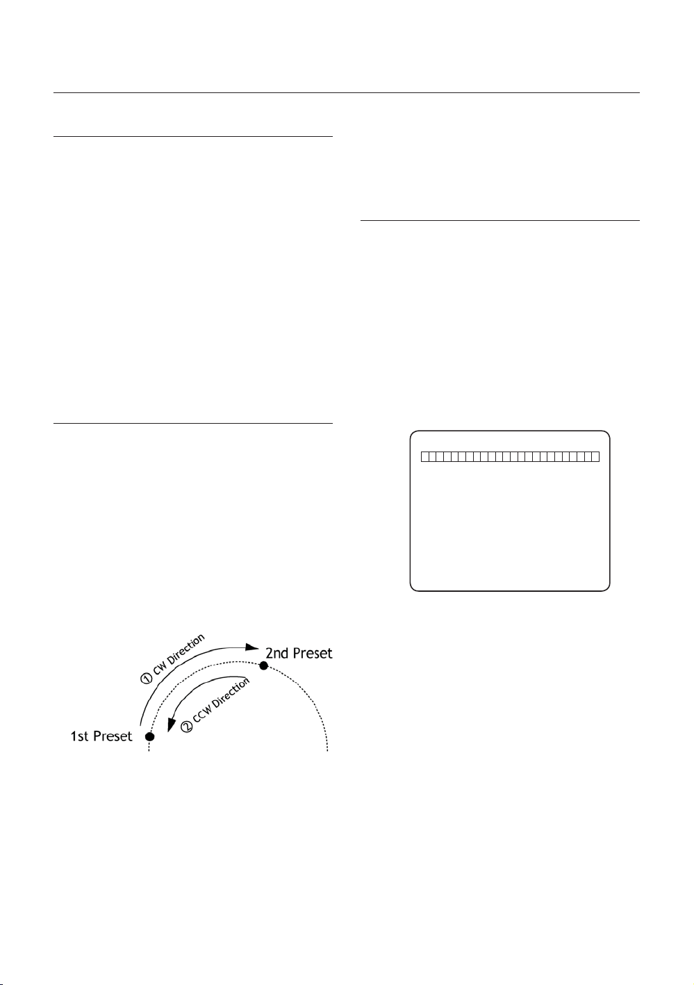
AUTO PAN
Function
•
By using Auto Pan function, you can make camera
to move between 2 Preset positions repeatedly.
When Auto Pan function runs, camera moves
from the preset assigned as the 1st point to the
preset assigned as the 2nd point in CW(Clockwise)
direction. Then camera moves from the preset
assigned as the 2nd point to the preset assigned as
the 1st point in CCW(Counterclockwise) direction.
In case that the preset assigned as the 1st point
is same as the preset assigned as the 2nd point,
camera turns on its axis by 360° in CW(Clockwise)
direction and then it turns on its axis by 360° in
CCW(Counterclockwise) direction.
Speed can be set up from 1°/sec to 180°/sec.
Set Auto Pan
•
To set Auto Pan, use OSD menu.
•
Run Auto Pan
Method1) <Run Auto Pan> [Auto Pan NO.] [Enter]
Method2) <Go Preset> [Auto Pan NO.+140]
ex) Run Auto Pan 2 : <Go Preset> [142]
•
Delete Auto Pan
To delete Auto Pan, use OSD menu.
PATTERN
Function
•
Pattern Function is that a camera memorizes the path
(mostly curve path) by joystick of controller for assigned
time and revives the path exactly as it memorized.
4 Patterns are available and Maximum 1000
communication commands can be stored in a pattern.
Set Pattern
•
Pattern can be created by one of following two
methods.
Method 1) <Set Pattern> [Pattern NO.]
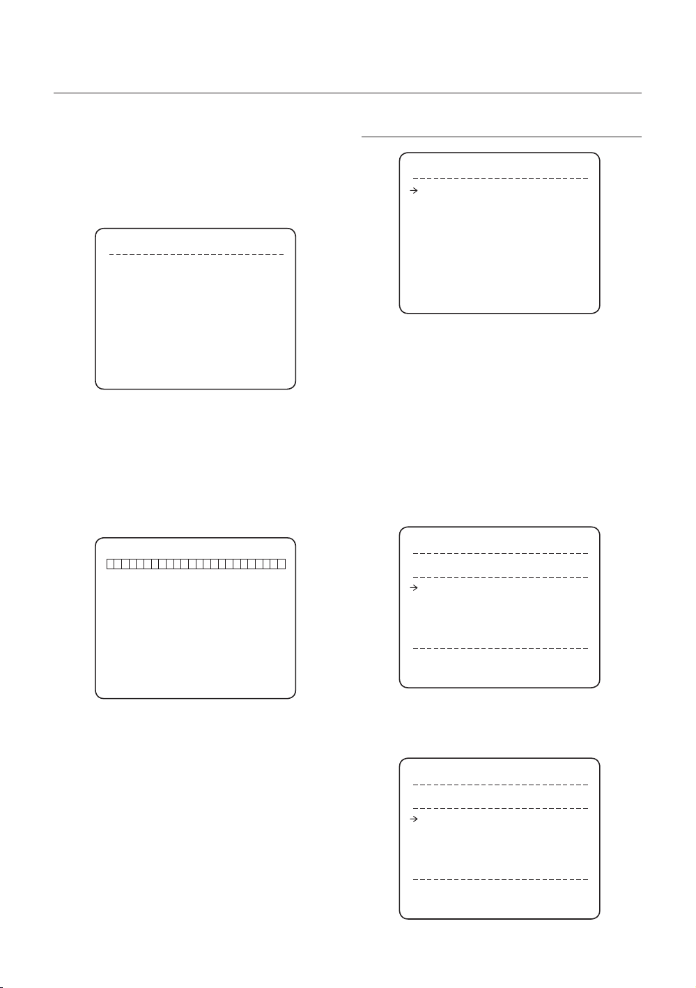
Pattern editing screen is displayed as bellow.
–
EDIT PATTERN 1
[NEAR:SAVE / FAR:DELETE]
Movement by Joystick and preset movement
–
can be memorized in a pattern.
The rest memory size is displayed in progress
–
bar.
To save the recording, press NEAR key and to
–
cancel, press FAR key.
Method 2) OSD Using OSD Menu: See the section
“How to use OSD Menu”.
Run Pattern
•
Method 1) <Run Pattern> [Pattern NO.] [Enter]
ex) Run Pattern 2 : <Run Pattern> [2] [Enter]
Method 2) <Go Preset> [Pattern NO.+130]
ex) Run Pattern 2: <Go Preset> [132]
Delete Pattern
•
Use OSD menu to delete a Pattern.
a When the PATTERN is saved/executed, the PAN/
TILT is operated with AUTO FLIP OFF.
0/0/X1/N
16 – 36x SMART DOME CAMERA
Operation
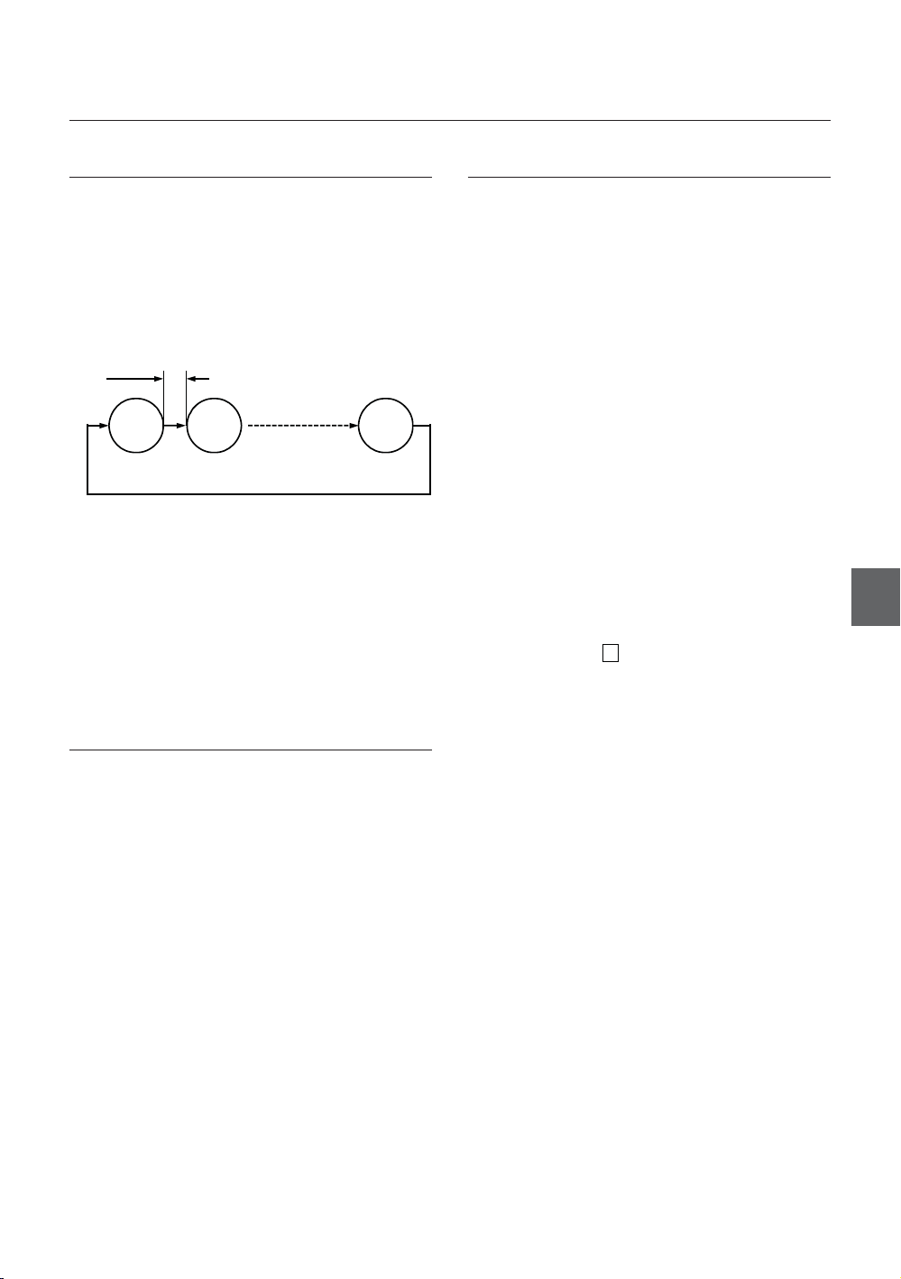
SCAN
Function
•
The Scan function allows running sequence of
Presets, Pattern and/or Auto Pans. Max 8 Scan
can be stored. Each Scan can have max 20 action
entities which can be preset, pattern or Auto Pan.
Preset speed can be set up and the repeat number
of Pattern & Auto Pan can be set up in Scan setup.
Dwell time between actions can be set up also.
Dwell Time
Preset 1
Set Scan
•
Use OSD Menu to create a Scan.
Run Scan
•
Method1) <Run Scan> [Scan NO] [Enter]
Method2) <Go Preset> [Scan NO.+150]
ex) Run Scan 7 : <Go Preset> [157]
Delete Scan
•
Use OSD Menu to delete.
Pattern 1
Max 20 Entities
Scan 1
SCHEDULE
Function
•
The Schedule function allows running an appropriate
function like Preset, Auto Pan, Scan, Pattern, Home
move at designated day and time. For example, if
you setup a rule Tuesday at 9:00AM and Preset 1
(say Main Gate), the camera will move to main gate
every Tuesday at 9:00AM. If you choose Weekday,
camera will move to Main gate everyday except
weekend.
It is noted that due to the real time clock, the time
data will be kept regardless of blackout. The initial
time and day setup is essential to proper Schedule
function.
Set Schedule
•
Use OSD Menu to create a Schedule
Run Schedule
•
Use OSD Menu of Schedule Master Enable
•
Delete Schedule
Use OSD Menu to delete.
OTHER FUNCTIONS
Preset Lock
•
This function is made to protect preset data from
unauthorized overwriting. If Preset Lock is ON,
Preset save command using Hot Key is disabled
while Preset save using OSD Menu is acceptable.
Power Up Action
•
This function enables to resume the last action
executed before power down. Most of actions such as
Preset, Pattern, Auto Pan and Scan are available for this
function but Jog actions are not available to resume.
if there are no setup for those functions like
Preset, Pattern, Auto Pan and Scan, Camera will
automatically move to Home position after rebooting.
If Power Up Action is set to be ON, camera will
continue the function which is executed lastly after
rebooting.
Auto Flip
•
In case that tilt angle arrives at the top of tilt orbit
(90°), zoom module camera keep moving to opposite
tilt direction (180°) to keep tracing targets. As soon
as zoom module camera passes through the top
of tilt direction(90°), images should be reversed
automatically and F appears in screen. If this
function is set to OFF, tilt movement range is 0 ~ 90°.
Parking Action
•
This function enables to locate the camera to specifi c
position automatically if operator doesn’t operate the
controller for a while. The Park Time can be defi ned
as an interval from 5 seconds to 4 hours.
Alarm Input
•
8 Alarm Inputs are used. If an external sensor
is activated, camera can be set to move to
corresponding preset position. It is noted that the
latest alarm input is effective if multiple sensors are
activated.
Alarm Output
•
There are 4 Ch. of Alarm Outputs and all of them
can be assigned to a certain Preset number. For
example, if you assign Preset 5 to AO2, calling
Preset 5 result in turning On of AO2.
Privacy Zone Mask
•
To protect privacy, MAX. 8 Privacy Masks can be
created on the arbitrary position to hide objects such
as windows, shops or private house. With Spherical
Coordinates system, powerful Privacy Zone Mask
function is possible.
GENERAL/SPECIAL Image Setup
•
WB (White Balance) and AE (Auto Exposure) can
ENG
English – 17

Operation
be set up independently for each preset. There
are 2 modes, “General” mode & “Special” mode.
The General mode means that WB or AE can be
set up totally and simultaneously for all presets in
“ZOOM CAMERA SETUP” menu. The Special mode
means that WB or AE can be set up independently
or separately for each preset in each preset setup
menu. Each Special WB/AE value should activate
correspondingly when camera arrives at each preset
location.
During jog operation, General WB/AE value should
be applied. All Special WB/AE value will not be
changed although General WB/AE value change.
•
Semi Auto Focus
This mode exchanges focus mode automatically
between Manual Focus mode and Auto Focus mode
by operation. Manual Focus mode activates in preset
operation and Auto Focus mode activates during jog
operation. With Manual mode at presets, Focus data
is memorized in each preset in advance and camera
calls focus data in correspondence with presets as
soon as camera arrives at a preset. It should shorten
time to get focuses.
Focus mode changes to Auto Focus mode
automatically when jog operation starts.
“PRESET ×××”
“PATTERN ×”
“AUP×/PRESET ×××”
“UNDEFINED”
Preset Label
•
The Label stored for specifi c Preset.
Alarm Information
•
This information shows current state of Alarm Input.
The “I” means Input and “O” is output. If an Input is
ON state it will show the number of input. If an Input
is OFF state, ‘-’ will be displayed. In the same way
“O :1” means output 1 is ON “O :-“ is OFF.
Ex) When Point 2 of inputs are ON, and Output 1 is
On, OSD will show as below
•
Image Flip
Shows that images are currently reversed by Auto
Flip Function.
•
Date/Time
Displays Current Date and Time.
OSD DISPLAY OF MAIN SCREEN
Action Title
Alarm Information
Image Flip
Camera ID
LABEL12345
PRESET1
P/T/Z Information
Preset Lable 1
Date/Time
Camera ID
P/T/Z Information
•
Current Pan/Tilt angle in degree, zoom magnifi cation
and a compass direction.
Camera ID
•
Current Camera ID(Address).
•
Action Title
Followings are possible Action Titles and their meaning.
“SET PRESET ×××”
18 – 36x SMART DOME CAMERA
GENERAL RULES OF KEY
OPERATION FOR MENU
•
The menu items surrounded with < > always has its
sub menu.
For all menu level, to go into sub menu, press NEAR
•
or ENTER key.
To go to up-one-level menu, press FAR key.
•
To move from items to item in the menu, use joystick
•
in the Up/Down or Left/Right.
To change a value of an item, use Up/Down of the
•
joystick in the controller.
Press NEAR or ENTER key to save values and
•
Press FAR key to cancel values.
How to use OSD Menu
MAIN MENU
ROOT MENU
<SYSTEM INFORMATION>
<DISPLAY SETUP>
<MOTION SETUP>
<FUNCTION SETUP>
<CAMERA SETUP>
<SYSTEM SETUP>
<SYSTEM INITIALIZE>
EXIT
System Information
•
Shows info and current confi guration.
Display Setup
•
Enable/Disable of OSD display on Main Screen.
Motion Setup
•
Setup for motion related settings
Function Setup
•
Setup for various functions such as Preset, Auto
Pan, Pattern, Scan and Schedule.
Camera Setup
•
Confi gure Camera related functions and data
System Setup
•
Confi gure for Basic system setup.
System Initialize
•
Initializes system confi guration and sets all data to
factory default confi guration.
SYSTEM INFORMATION
Baud rate Shows current Baud rate of PTZ
•
control.
Address Shows current Camera ID for PTZ
•
control.
DISPLAY SETUP
DISPLAY SETUP
CAMERA ID ON
PTZ INFORMATION AUTO
ACTION TITLE AUTO
RESET LABEL AUTO
ALARM I/O AUTO
DATE/TIME ON
<PRIVACY ZONE>
BACK
EXIT
This menu defi nes Enable/Disable of OSD display on
Main Screen. If an item is set to be AUTO, the item is
displayed only when the value of it is changed.
Camera ID [ON/OFF]
•
PTZ Information [ON/OFF/AUTO]
•
Action Title [ON/OFF/AUTO]
•
Preset Label [ON/OFF/AUTO]
•
Alarm I/O [ON/OFF/AUTO]
•
Date/Time [ON/OFF]
•
<Privacy Zone> Start Privacy Zone Mask
•
setup Menu.
PRIVACY ZONE MASK SETUP
Select area in image to mask.
Mask No. [1~8]
•
ENG
SYSTEM INFORMATION
FIRMWARE VER 1.00S36
COLOR SYSTEM NTSC
PROTOCOL SAMSUNG
BAUD RATE 9600
ADDRESS 255
BACK
EXIT
Firmware Ver.
•
Shows current fi rmware version of camera.
Color System
•
Shows current analog video system of the camera.
•
Protocol
Shows current Protocol for PTZ control
PRIVACY ZONE
MASK NO. 1
UNDEFINED
DISPLAY OFF
CLEAR MASK CANCEL
<EDIT MASK>
BACK
EXIT
Select Mask number. If the selected mask has
already data, camera moves as it was set.
Otherwise, “UNDEFINED” will be displayed under
“Mask NO”.
English – 19
How to use OSD Menu
Display [ON/OFF]
•
Sets if camera makes mask shows or not on images.
Clear Mask [CANCEL/OK]
•
Deletes data in the selected mask NO.
Privacy Zone Area Setup
❖
EDIT MASK 1
MOVE TO TARGET POSITION
[NEAR:SELECT/FAR:CANCEL]
0/0/x1/N
Move camera to area to mask. Then the menu to
adjust mask size will be displayed.
If the tilt angle is located in the range between 90°
to 90°, you can not set up privacy zone mask.
If tilt angle over 90° (image fl ipped region) is
designated, camera will automatically move to
identical poison by changing tilt angle less than 90°
and moving pan angle 180 relatively.
Privacy Zone Size Adjustment
❖
EDIT MASK 1
[ZOOM : COLOR CHANGE]
[◄►:ADJUST MASK WIDTH]
[▲▼:ADJUST MASK HEIGHT]
[NEAR:SAVE / FAR:CANCEL]
Adjust mask size. Use joystick or arrow buttons to
adjust mask size.
◄► (Left/Right) Adjusts mask width.
•
▲▼ (Up/Down) Adjusts mask height.
•
•
Zoom In/Out Change Color of mask.
To hide a certain zone completely regardless of high
speed PT motions, it is recommended that the size of
mask must be 20% bigger than original target size.
It is noted that during PAN/TILT control like jog
action, the object behind the privacy mask can be
disclosed in a short period of time.
MOTION SETUP
MOTION SETUP
PRESET LOCK OFF
PWR UP ACTION ON
AUTO FLIP ON
JOG MAX SPEED 140/SEC
JOG DIRECTION INVERSE
FRZ IN PRESET OFF
<PARKING ACTION SETUP>
<ALARM INPUT SETUP>
BACK
EXIT
Setup the general functions of Pan/Tilt motions.
Preset Lock [ON/OFF]
•
If Preset Lock is set to ON, it is impossible to set up
and delete Preset, APAN, Pattern and SCAN. It is
possible only to run those functions. To set up and
delete those functions, enter into OSD menu.
Power Up Action [ON/OFF]
•
Refer to “Other Functions”(page 17) section.
Auto Flip [ON/OFF]
•
Refer to “Other Functions”(page 17) section.
Jog Max Speed [2°/sec ~200°/sec]
•
Sets maximum jog speed. Jog speed is inversely
proportional to ratio of zoom. As zoom magnifi cation
goes up, pan/tilt speed goes down.
Jog Direction [INVERSE/NORMAL]
•
If you set this to ‘Normal’, the view in the screen is
moving same direction with jog tilting. If ‘Inverse’ is
selected, the view in the screen is moving reversely.
Freeze in Preset [ON/OFF]
•
At start point of preset movement, camera starts
freezing the image of start point. Camera keeps
displaying the image of start point during preset
movement and does not display the images which
camera gets during preset movement. As soon as
camera stops at preset end point, camera starts
displaying live images which it gets at preset end
point.
20 – 36x SMART DOME CAMERA
Parking Action Setup
❖
How to use OSD Menu
FUNCTION SETUP
PARKING ACTION SETUP
PARK ENABLE OFF
WATT TIME 00:10:00
PARK ACTION HOME
BACK
EXIT
If Park Enable is set to ON, camera runs assigned
function automatically if there is no PTZ command
during assigned “Wait Time”.
Park Enable [ON/OFF]
•
Wait Time [5 sec ~ 4 hour]
•
The time is displayed with “hh:mm:ss” format and
you can change this by 1 sec unit.
Park Action
•
[HOME/PRESET/PATTERN/AUTOPAN/SCAN]
Ex) If HOME is selected for Park Action, camera
will move to home position when there is no PTZ
command during assigned “Wait Time.”
Alarm Input Setup
❖
ALARM INPUT SETUP
ALARM1 N.0 PRESET1
ALARM2 N.0 NOT USED
ALARM3 N.0 NOT USED
ALARM4 N.0 NOT USED
ALARM5 N.0 PRESET1
ALARM6 N.0 NOT USED
ALARM7 N.0 NOT USED
ALARM8 N.0 NOT USED
BACK
EXIT
FUNCTION SETUP
<PRESET SETUP>
<AUTO PAN SETUP>
<PATTERN SETUP>
<SCAN SETUP>
<SCHEDULE SETUP>
BACK
EXIT
Confi gure 5 Special Functions with this menu
Preset Setup
•
127 Presets from the number 1 to 128 can be
assigned excluding preset 95 reserved for Menu.
Auto Pan Setup
•
Up to 8 Auto Pans are available, which makes
camera to move slowly between two preset points.
Pattern Setup
•
Up to 4 patterns can be stored in the dome.
In this function, path data created by manual move
of Joystick are recorded and you can playback the
identical path automatically whenever required.
Scan Setup
•
Up to 8 Scans can be defi ned.
In a Scan, max 20 entities are assigned from any
combinations of Preset/Auto Pan/Pattern. If you run
a Scan, camera will execute each entry sequentially.
•
Schedule Setup
7 rules of Schedule can be assigned by day and
time. Appropriate actions (such as Home, Preset,
Auto Pan, Pattern and Scan) can be defi ned for
each rule. Also, it is possible to use Weekday and
Weekend in a rule to make it simple.
ENG
Match the Alarm sensor input to one of Preset
positions. If an external sensor is activated, camera
will move to corresponding preset position when this
item is predefi ned.
•
Alarm Type
[Normal OPEN(N.O) / Normal CLOSE(N.C)]
Sets sensor input type.
•
Alarm Action
[NOT USED/HOME/PRESET 1~128/APAN 1~8,
PATTERN1~4, SCAN 1~4]
For each Alarm input, you can assign counteraction
functions (Preset, Auto Pan, Pattern, Scan).
English – 21
How to use OSD Menu
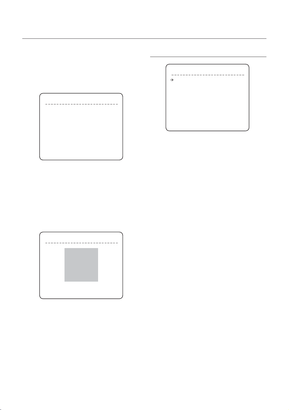
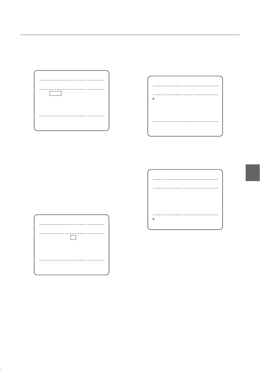
Edit Preset Scene
PRESET SETUP
❖
PRESET SETUP
PRESET NO. 1
<EDIT SCENE>
<LABEL> WINDOWS
CLR PRESET CANCEL
CAM ADJUST GENERAL
ALARM OUT ----
BACK
EXIT
Preset Number [1~128]
•
If a selected preset is already defi ned, camera moves
to pre-defi ned position and preset characteristics
such as Label and Relay Outputs show on monitor.
If a selected preset is not defi ned, “UNDEFINED”
shows on monitor.
•
Edit Scene
Redefi ne current Preset scene position (i.e. PTZ).
Label
•
Edits Label to show on monitor when preset runs.
MAX. 10 alphabets are allowed.
CLR Preset [CANCEL/OK]
•
Delete current Preset data
CAM Adjust [GENERAL/SPECIAL]
•
WB(White Balance) and AE(Auto Exposure) can
be set up independently for each preset. There are
2 modes, “General” mode & “Special” mode. The
General mode means that WB or AE can be set up
totally and simultaneously for all presets in “CAMERA
SETUP” menu.
The Special mode means that WB or AE can be
set up independently or separately for each preset
in each preset setup menu. Each Special WB/AE
value should activate correspondingly when camera
arrives at each preset location. During jog operation,
General WB/AE value should be applied.
All Special WB/AE value should not change although
General WB/AE value changes. If “Special’’ is
selected, Menu to set WB/AE shows on monitor.
Alarm out
•
State of four alarm outputs can be freely controlled in
conjunction with Preset run. The character “-“ means
OFF state and the number representing each bit
means ON.
Ex) If it is set to be -23-, Output relay 2, 3 will be ON
and 1, 4 will be OFF, when you run this Preset.
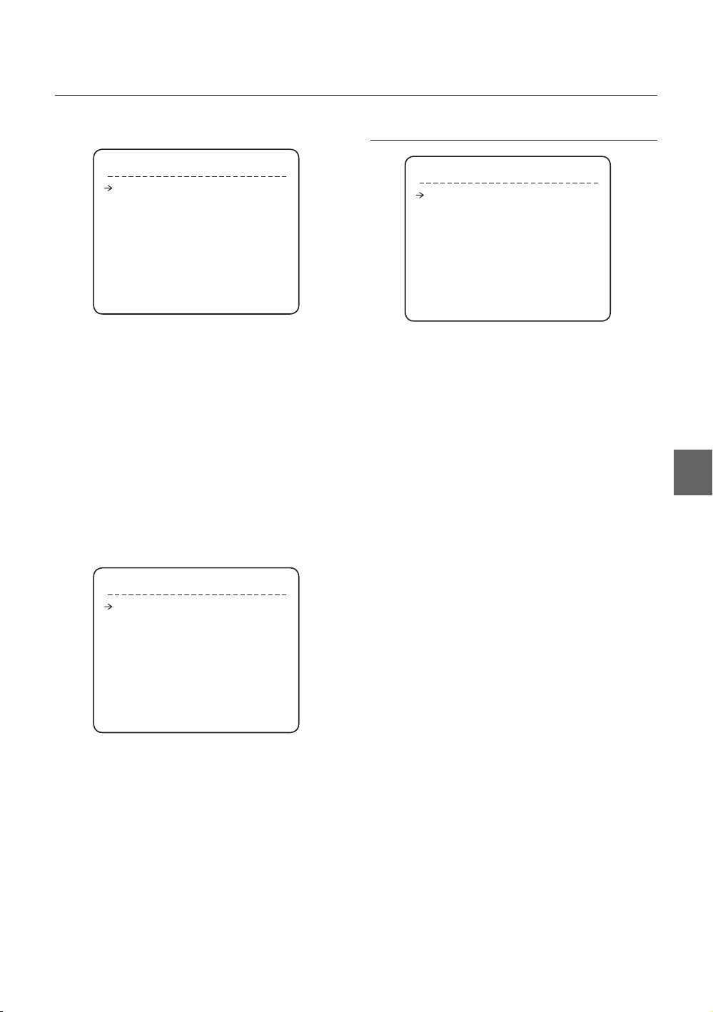
EDIT SCENE - PRESET 1
MOVE TO TARGET POSITION
[NEAR:SAVE / FAR:CANCEL]
0/0/x1/N
① Using joystick, move camera to desired position.
② By pressing NEAR or ENTER key, save current
PTZ data.
③ Press FAR key to cancel.
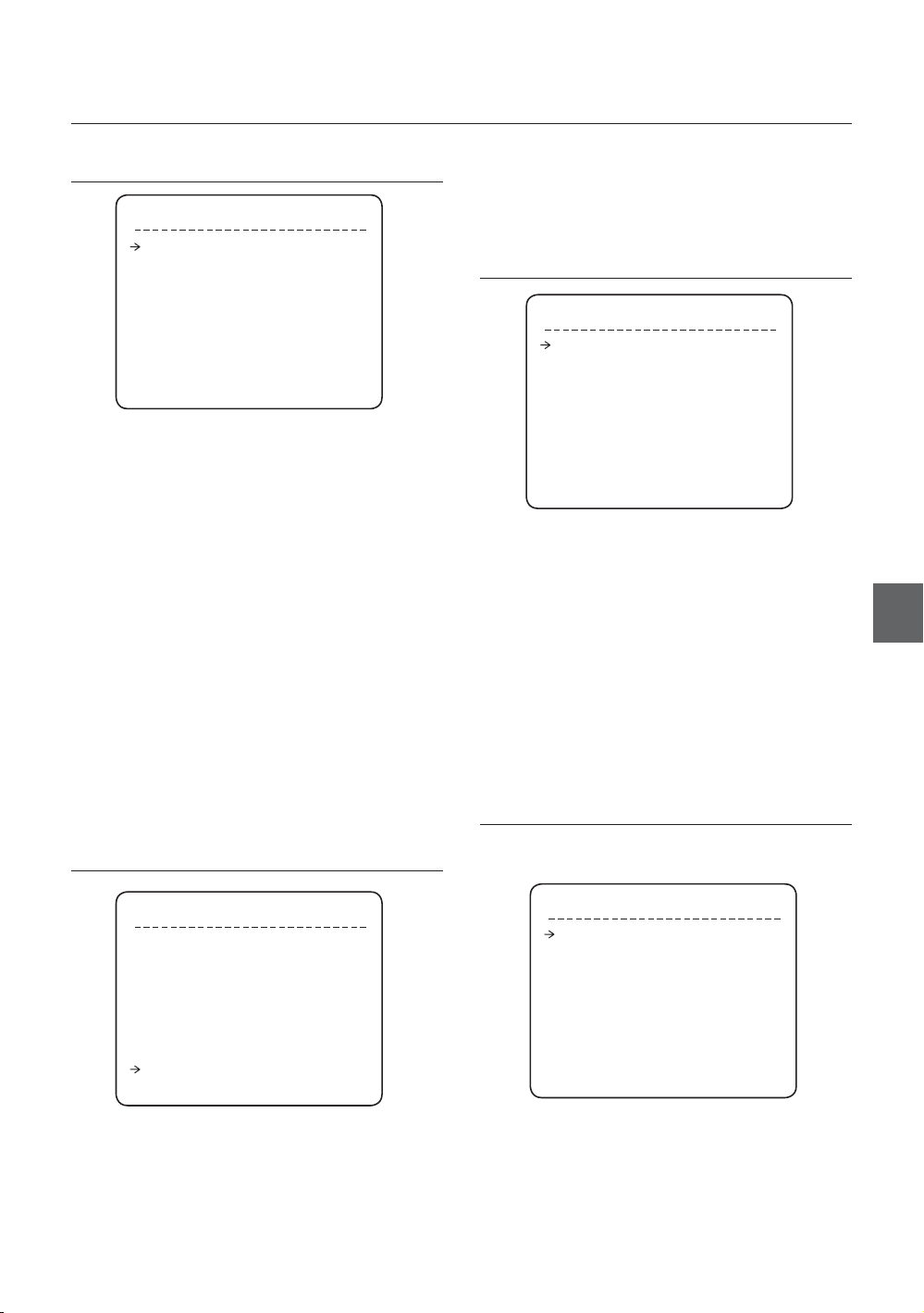
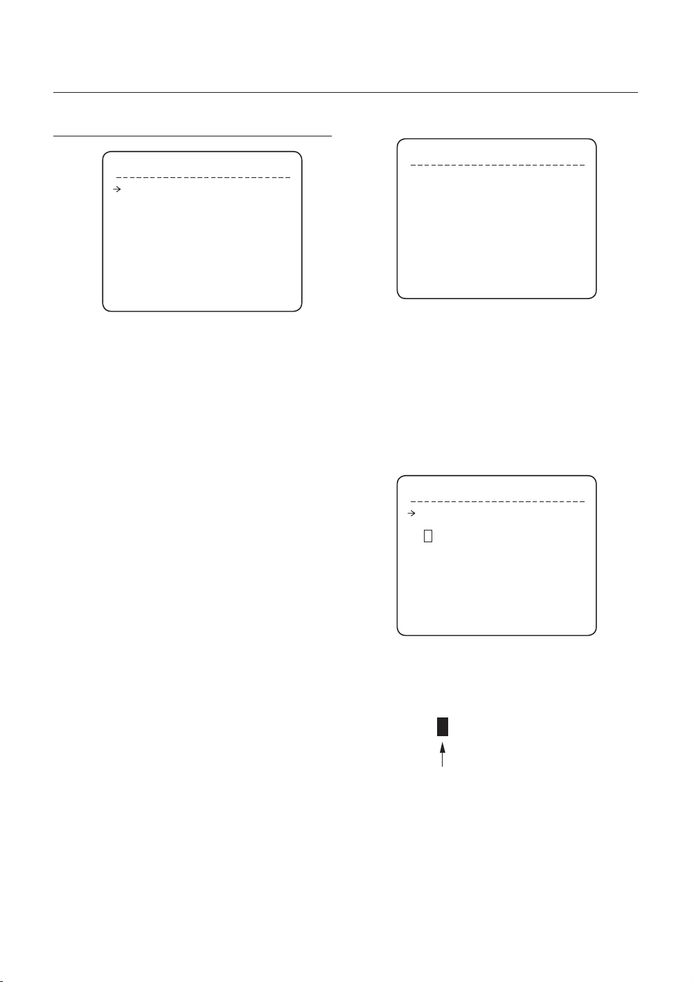
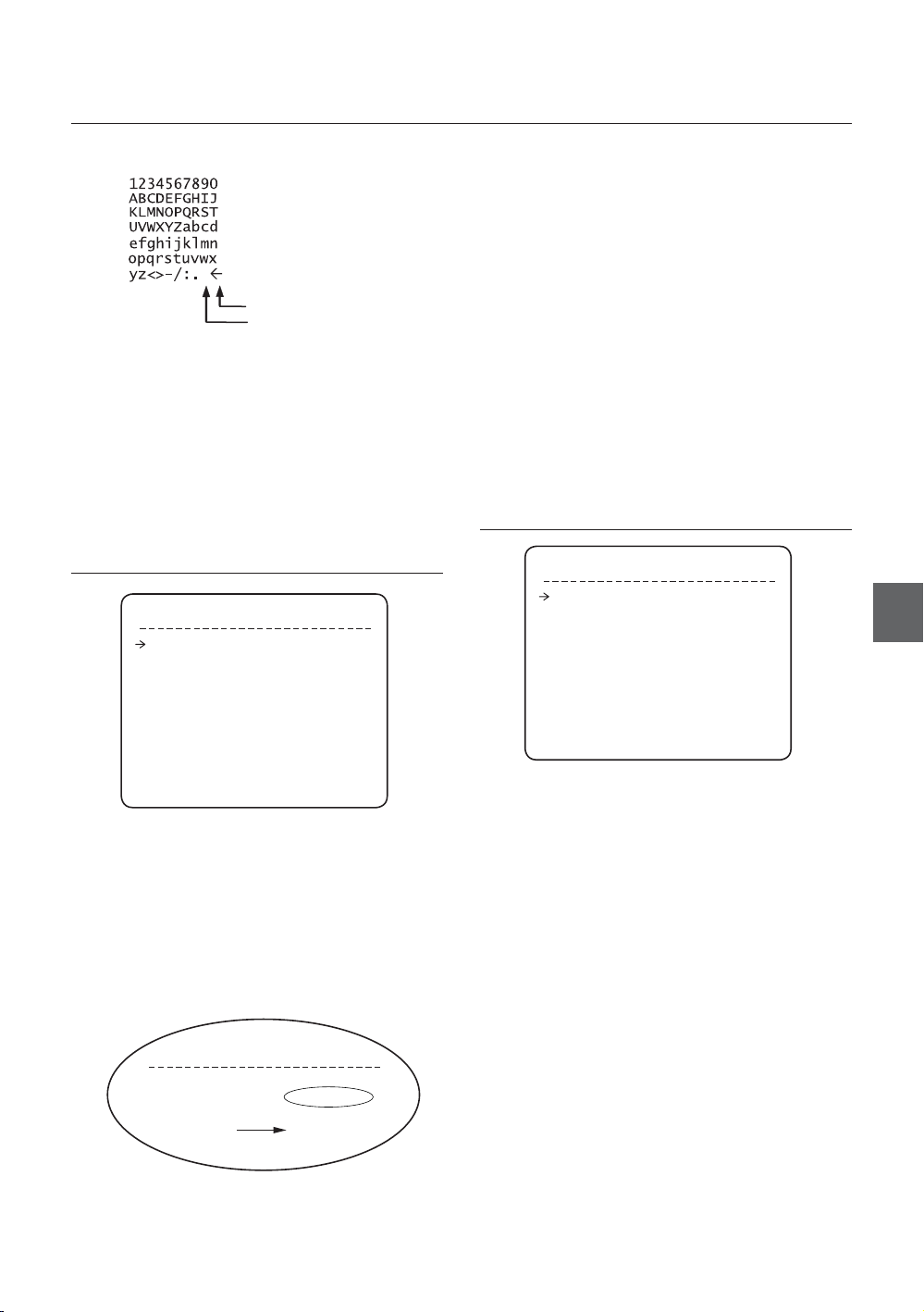
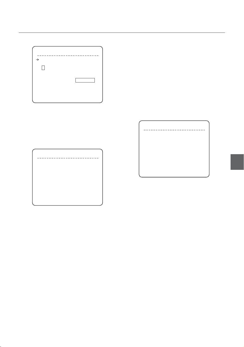
Edit Preset Label
❖
LABEL - PRESET 1
[█ ]
--------- 1234567890 OK
ABCDEFGHIJ CANCEL
KLMNOPQRST
UVWXYZabcd
efghijklmn
opqrstuvwx
yz<>-/:.
①
Edits label to show on monitor when camera
arrives at presets. In Edit Label menu, a reverse
rectangular is cursor. As soon as fi nishing
selecting alphabet, cursor moves to the next digit.
[ ]
Current Cursor Position
② Using Left/Right/Up/Down of joystick, move to
an appropriate character from the Character set.
To choose that character, press the NEAR or
ENTER key.
22 – 36x SMART DOME CAMERA
How to use OSD Menu
Back Space Char.
Space Char.
If you want to use blank, choose Space
character (“ ”). If you want to delete a character
before, use back space character (“”).
③ If you complete the Label editing, move cursor
to “OK” and press NEAR or ENTER key to save
completed label. To abort current change, move
cursor to “Cancel” and press NEAR or ENTER key.
When Auto Pan function runs, camera moves
from the preset assigned as the 1st point to the
preset assigned as the 2nd point in CW(Clockwise)
direction. Then camera moves from the preset
assigned as the 2nd point to the preset assigned as
the 1st point in CCW(Counterclockwise) direction.
In case that the preset assigned as the 1st point
is same as the preset assigned as the 2nd point,
camera turns on its axis by 360° in CW direction and
then it turns on its axis by 360° in CCW direction.
APAN(AUTO PAN) Speed [1°/sec ~180°/sec]
•
Sets Auto Pan speed from 1°/sec to 180°/sec.
Clear APAN(AUTO PAN) [CANCEL/OK]
•
Deletes current Auto Pan data.
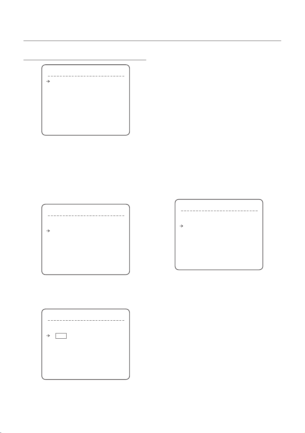
PATTERN SETUP
AUTO PAN SETUP
AUTO PAN SETUP
APAN NO. 1
1ST POS. NOT USED
2ND POS. NOT USED
APAN SPEED
CLEAR APAN CANCEL
BACK
EXIT
Auto Pan Number [1~8]
•
Selects Auto Pan number to edit. If a selected Auto
Pan has not defi ned, “NOT USED” is displayed in 1st
Position and 2nd Position
•
1st Position / 2nd Position [PRESET 1~128]
Set up the 2 position for Auto Pan function. If a
selected preset is not defi ned, “UNDEFINED” will be
displayed as shown below.
AUTO PAN SETUP
APAN NO. 1
1ST POS. PRESET5
2ND POS. PRESET8
UNDEFINED
30/SEC
PATTERN SETUP
PATTERN NO. 1
UNDEFINED
CLEAR PATTERN CANCEL
<EDIT PATTERN>
BACK
EXIT
Pattern Number [1~4 ]
•
Selects Pattern number to edit.
If a selected pattern number is not defi ned,
“UNDEFINED” will be displayed under selected
pattern number.
Clear Pattern [CANCEL/OK]
•
Deletes data in current pattern
Edit Pattern
•
Starts editing pattern.
ENG
English – 23
How to use OSD Menu
❖
Edit Pattern
SCAN SETUP
① By using Joystick, move to start position with
appropriate zoom. To start pattern recording,
press NEAR or ENTER key. To exit this menu,
press FAR key.
EDIT PATTERN 1
MOVE TO START POSITION
[NEAR:START/ FAR:CANCEL]
0/0/x1/N
② Move camera with joystick of controller or run
preset function to memorize the path (mostly
curve path) in a selected pattern. The total
memory size and the rest memory size is
displayed in the form of bar. Maximum 1,000
communication commands can be stored in a
pattern.
EDIT PATTERN 1
[NEAR:SAVE / FAR:DELETE]
0/0/X1/N
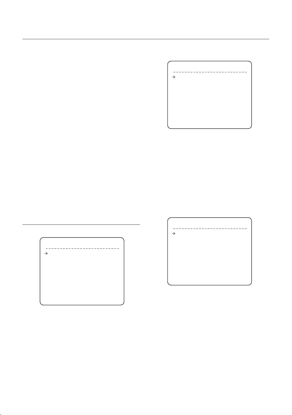
SCAN SETUP
SCAN NO. 1
UNDEFINED
CLEAR SCAN CANCEL
<EDIT SCAN>
BACK
EXIT
Scan Number [1~8]
•
Selects Scan number to edit.
If a selected Scan number is not defi ned,
“UNDEFINED” will be displayed under selected Scan
number.
Clear Scan [CANCEL/OK]
•
Deletes data in current Scan
Edit Scan Starts editing Scan.
•
Edit Scan
❖
① Press NEAR or ENTER key in “NO” list to start
Scan setup.
EDIT SCAN 1
NO. ACTION NO. DWELL OPT
1 NONE
2 NONE
3 NONE
4 NONE
5 NONE
SAVE
CANCEL [NEAR:EDIT]
③ To save data and exit, press NEAR or ENTER
key. To cancel recording and delete record
data, press FAR key.
24 – 36x SMART DOME CAMERA
② Note that MAX. 20 Functions are allowed in a
Scan. Move cursor up/down and press NEAR
or ENTER key to set up.
EDIT SCAN 1
NO. ACTION NO. DWELL OPT
1 NONE
2 NONE
3 NONE
4 NONE
5 NONE
SAVE [NEAR:EDIT ACT]
CANCEL [FAR :EDIT END]
How to use OSD Menu
③ Set up Action, Dwell time and Option. Note
that selected item is displayed in reverse. Move
cursor Left/Right to select items and move
cursor Up/Down to change each value.
EDIT SCAN 1
NO. ACTION NO. DWELL OPT
1 NONE
2 NONE
3 NONE
4 NONE
5 NONE
SAVE [◄►:MOVE CURSOR]
CANCEL [▲▼:CHANGE VAL.]
•
Action NO.
[NONE/PRESET/AUTO PAN/PATTERN]
•
DWELL [1 second ~ 4 minutes]
Sets Dwell Time between functions
•
OPT
Option. It represents preset speed (2~360)
when preset is selected. It should be the
number of repetition (1~255) when Pattern or
Auto Pan is selected for Action
④ Set up items such as Action, NO., Dwell and
OPT.
EDIT SCAN 1
NO. ACTION NO. DWELL OPT
1 PRESET 1 00:03 360
2 NONE
3 NONE
4 NONE
5 NONE
SAVE [◄►:MOVE CURSOR]
CANCEL [▲▼:CHANGE VAL.]
⑤ After fi nishing setting up an Action, press NEAR
or ENTER key to one-upper-level menu (Step
②). Move cursor Up/Down to select Action
number and repeat Step ② ~ Step ④ to edit
selected Scan.
EDIT SCAN 1
NO. ACTION NO. DWELL OPT
1 PRESET 1 00:03 360
2 NONE
3 NONE
4 NONE
5 NONE
SAVE [NEAR:EDIT ACT]
CANCEL [FAR :EDIT END]
⑥ After fi nishing setting up all Actions, press FAR
key to exit. Then cursor should be moved to
“SAVE.” Press NEAR or ENTER key to save
data.
EDIT SCAN 1
NO. ACTION NO. DWELL OPT
1 PRESET 1 00:03 360
2 NONE
3 NONE
4 NONE
5 NONE
SAVE
CANCEL
ENG
English – 25
How to use OSD Menu
SCHEDULE SETUP
SCHEDULE SETUP
MASTER ENABLE ON
DAY TIME ACT NO ON
1 UNDEFINED
2 UNDEFINED
3 UNDEFINED
4 UNDEFINED
5 UNDEFINED
6 UNDEFINED
7 UNDEFINED
BACK
Master Enable [ON/OFF]
•
Decide whether Schedule function is active or not.
Edit Schedule
❖
① After move the Cursor to the number by using
Up/Down keys, press “NEAR”(Enter) Key to
edit.
SCHEDULE SETUP
MASTER ENABLE ON
DAY TIME ACT NO ON
1 UNDEFINED
2 UNDEFINED
3 UNDEFINED
4 UNDEFINED
5 UNDEFINED
6 UNDEFINED
7 UNDEFINED
BACK
② Each fi eld can be selected by Left/Right keys
and the values in the fi eld are changed using
Up/Down keys.
SCHEDULE SETUP
MASTER ENABLE ON
DAY TIME ACT NO ON
1 MON 00:00 HOM OFF
2 UNDEFINED
3 UNDEFINED
4 UNDEFINED
5 UNDEFINED
6 UNDEFINED
7 UNDEFINED
BACK
The meaning of each value:
DAY Days: MON TUE WED THU
FRI SAT SUN
WKD: Weekday
ALL: All days(Everyday)
TIME 24hour Format
ACT PRS(Preset), AUP(Auto Pan),
PTN(Pattern), SCN(Scan),
HOM(Home)
ON/OFF Decide to make this rule effective or
not
If you fi nish a rule, press NEAR or ENTER key
to select another rule.
Repeat this procedure to fi ll up the schedule in
mind.
③ Example
The second rule means camera will move
–
to Preset 12 position at 7:35 on every
Wednesday.
SCHEDULE SETUP
MASTER ENABLE ON
DAY TIME ACT NO ON
1 MON 01:20 HOM ON
2 WED 07:35 PRS 12 ON
3 THU 11:40 SCN 3 ON
4 SAT 15:17 PTN 1 ON
5 WKD 23:00 HOM ON
6 UNDEFINED
7 UNDEFINED
BACK
* Note: If there are rules confl icts to each other, the
higher number is, the higher priority has.
* Note: If you assign undefi ned function, there will
be no action.
* Hint: Using reserved Preset, you can make
various schedules. For example, PRS179 are
PRS178 are Day and Night mode respectively.
(Refer to Reserved Preset(page 15) List in this
manual.)
26 – 36x SMART DOME CAMERA

CAMERA SETUP
How to use OSD Menu
❖
White Balance Setup
Setup the general functions of zoom camera module
ZOOM CAMERA SETUP
FOCUS MODE SEMIAUTO
DIGITAL ZOOM ON
IMAGE FLIP OFF
FLICKERLESS OFF
<WHITE BALANCE SETUP>
<AUTO EXPOSURE SETUP>
BACK
EXIT
Focus Mode [AUTO/MANUAL/SEMIAUTO]
•
Sets camera focus mode.
SEMIAUTO Mode
This mode exchanges focus mode automatically
between Manual Focus mode and Auto Focus
mode. Manual Focus mode activates in preset
operation and Auto Focus mode activates when
jog operation starts.
With Manual mode at presets, Focus data is
memorized in each preset in advance and camera
calls focus data in correspondence with presets as
soon as camera arrives at a preset.
Digital Zoom [ON/OFF]
•
Sets digital zoom function to ON/OFF. If this is set to
OFF, optical zoom function runs but zoom function
stops at the end of optical zoom magnifi cation.
Image Flip [ON/OFF]
•
To display Upside down image.
Flickerless [ON/OFF]
•
Turn on or off the Flickerless function. In this function,
AE mode becomes Shutter Priority mode and shutter
speed value will be fi xed to 1/100 sec.
WB SETUP - GLOBAL
WB MODE AUTO
zRED ADJUST ---
zBLUE ADJUST ---
BACK
EXIT
WB Mode [AUTO/MANUAL]
•
In Manual mode, Red and Blue level can be set up
manually
Red Adjust [0~255]
•
Blue Adjust [0~255]
•
Auto Exposure Setup
❖
AE SETUP
WDR/BLC ALL OFF
DAY/NIGHT AUTO
AE MODE AUTO
IRIS LEVEL ---
GAIN LEVEL ---
SHUTTER SPD ---
BRIGHTNESS ---
BACK
EXIT
WDR/BLC [ ALL OFF / WDR ON / BLC ON ]
•
Select WDR(Wide Dynamic Range) or BLC(Backlight
Compensation) function. All OFF means turning off
both functions.
Day/Night [AUTO/DAY/NIGHT]
•
AUTO exchanges Day / Night
•
AE MODE AUTO / MANUAL / IRIS / SHUTTER
/ BRIGHT
AUTO: Full Auto mode for AE function
MANUAL: In manual mode. IRIS, GAIN, SHUTTER
SPEED can be changed in this mode.
IRIS: Iris priority mode. You can change IRIS while
others are adjusted automatically.
SHUTTER: Shutter priority mode. Shutter speed can
be changed while others are adjusted automatically.
BRIGHT: In this mode, you can assign AE value in
terms of Brightness.
ENG
English – 27
How to use OSD Menu
IRIS
•
[Works when AE MODE is MANUAL or IRIS model]
Range: CLOSE/F1.6/F2/F2.4/F2.8/F3.4/F4/F4.8/
F5.6/F6.8/F8/ F9.6/F11/F14/F16/F19/F22/F28.
(18 steps)
•
GAIN
[Works when AE MODE is MANUAL]
Enhances image brightness automatically in case
that luminance level of image signal is too low.
Range: -3/0/2/4/6/8/10/12/14/16/18/20/22/24/26/
28dB (16 steps)
•
Shutter Speed
[Works when AE MODE is MANUAL or SHUTTER
mode]
X64, X32, X16, X8, X4, X2,1/60,1/90,1/100,1/125,1/
180,1/250,1/350,1/500,1/725,1/1000,1/1500,1/
2000,1/4000,1/6000,1/10000
•
Brightness
[Works when AE MODE is BRIGHT]
Adjusts brightness of images. Iris, Shutter Speed and
Gain are adjusted automatically in correspondence
with this value. Range: 0~31 (32 steps)
•
•
It is noted that the range of date setup is limited
DATE/TIME SETUP
DATE 01/JAN/2008(TUE)
TIME 00:00:01(H/M/S)
BACK
EXIT
Time
Time is displayed in HH:MM:SS format.
Date/time Setup
After you press the NEAR or ENTER key, each fi eld
can be selected by Left/Right keys and the values in
the fi eld are changed using Up/Down keys. To save
the updated data, press the NEAR or ENTER key
again
from 01/JAN/2000 to 31/DEC/2037.
SYSTEM SETUP
SYSTEM SETUP
<DATE/TIME SETUP>
<RELAY TYPE>
<PASSWORD>
<SET HOME POSITION>
<SET NORTH DIRECTION>
LANGUAGE ENGLISH
BACK
EXIT
•
System Setup
You can set up DATE/TIME, RELAY TYPE,
PASSWORD, HOME POSITION, NORTH POSITION.
•
Date
Date is displayed in dd/mm/yyyy format. The day is
automatically calculated when you set the date.
RELAY TYPE SETUP
RELAY1 NORMAL OPEN
RELAY2 NORMAL OPEN
RELAY3 NORMAL OPEN
RELAY4 NORMAL CLOSE
BACK
EXIT
•
Relay Type Setup
Contact types of 4 Ch. RELAY OUTPUTS are
defi ned. (NORMAL OPEN / NORMAL CLOSE)
NORMAL OPEN
NORMAL CLOSE
28 – 36x SMART DOME CAMERA
How to use OSD Menu
EDIT PASSWORD
[█ ]
--------- 1234567890 OK
ABCDEFGHIJ CANCEL
KLMNOPQRST
UVWXYZabcd DISABLE
efghijklmn
opqrstuvwx
yz<>-/:.
----------
Password Setup
•
You can defi ne 4 characters long password. If this
function is set to ENABLE, it is required to type this
password whenever to enter OSD MENU.
It is noted that MASTER PSSWORD : “4321”
* Set Home Position?
When you replace the camera block or the
orientation of camera is changed due to
maintenance operations, it is very diffi cult to
maintain same pan orientation. Therefore, all
function data depending on pan orientation such
as preset, pattern, scan, auto pan, and privacy
zone mask are not useful any more accordingly.
However, even in this case, you can reuse the
data if you redefi ne Set Home Position on the
previous Home position. It is recommendable
to memorize the target scene of current Home
position.
SET NORTH DIRECTION
SET HOME POSITION
MOVE TO TARGET POSITION
[NEAR:SAVE / FAR:CANCEL]
Set Home Position
•
0/0/x1/N
HOME position means the origin of PAN angle
calculation. The value of PAN angle displayed on the
screen is based on this HOME position.
By using Joystick, move the camera to the desired
position and press ENTER (NEAR/SAVE).
It is noted that Home is not effective to Tilt angle.
If you change the location of Home position, all
horizontal locations of functions such as preset,
pattern, scan, auto pan, and privacy zone mask will
be shifted based on changed Home position.
If there are no setup for those functions like
Preset, Pattern, Auto Pan and Scan, Camera will
automatically move to Home position after rebooting.
If Power Up Action is set to be ON, camera will
continue the function which is executed lastly after
rebooting.
MOVE TO TARGET POSITION
[NEAR:SAVE / FAR:CANCEL]
•
Set North Direction
0/0/x1/N
You can set up North direction.
By using Joystick, move the camera to the desired
NORTH position and press ENTER (NEAR/SAVE).
The direction will be displayed in the screen
[PAN AXIS / TILT AXIS / ZOOM / DD]
DD is direction and will be displayed from:
N/NE/E/SE/S/SW/W/NW
•
Language
You can select a preferred Language of OSD display
from 7 choices.
[ENGLISH/ ESPAÑOL/ FRANÇAIS/ DEUTSCH/
ITALIANO/ РУССКИЙ/ PORTUGUÊS]
After selecting a language, press ENTER(NEAR) key.
ENG
English – 29

How to use OSD Menu
SYSTEM INITIALIZE
Motion Confi guration
•
SYSTEM INITIALIZE
CLEAR ALL DATA NO
CLR DISPLAY SET NO
CLR CAMERA SET NO
CLR MOTION SET NO
CLR FUNCTION SET NO
REBOOT CAMERA NO
REBOOT SYSTEM NO
BACK
EXIT
Clear All Data
•
Deletes all confi guration data such as display,
camera, motion setup and so on.
Clear Display Set
•
Initializes Display Confi guration
Clear Camera Set
•
Initializes Camera Confi guration
•
Clear Motion Set
Initializes Motion Confi guration
Clear Function Set
•
Deletes Preset Data, Auto Pan Data, Pattern Data,
Scan Data and Schedule Data
Reboot Camera
•
Reboots Zoom Camera module
Reboot System
•
Reboots Smart Dome Camera
Initial Confi guration Table
❖
Preset Lock OFF
Power Up Action ON
Auto Flip ON
Jog Max Speed 140°/sec
Jog Direction NORMAL
Freeze In Preset OFF
Park Action OFF
Alarm I/O Action OFF
Communication Setup
•
Protocol AUTO
Baud Rate 9600
Camera Confi guration
•
Focus Mode SEMIAUTO
Digital Zoom ON
Image Flip ON
Flickerless OFF
White Balance AUTO
Backlight/BLC ALL OFF
Day/Night AUTO
AE Mode AUTO
Iris Level F4
Gain Level +2dB
Shutter Speed 1/60
Brightness 13
Display Confi guration
•
Camera ID ON
PTZ Information AUTO
Action Title AUTO
Preset Label AUTO
Alarm I/O AUTO
Date/Time ON
Privacy Zone Undefi ned
30 – 36x SMART DOME CAMERA
Function Data
•
Preset 1~128 Undefi ned
Auto Pan 1~8 Undefi ned
Pattern 1~4 Undefi ned
Scan 1~8 Undefi ned
Schedule 1~7 Undefi ned
 Loading...