

Samsung SCC-C6475P User Manual [es]
SCC-C6475(P)
E
D
F
Es
I
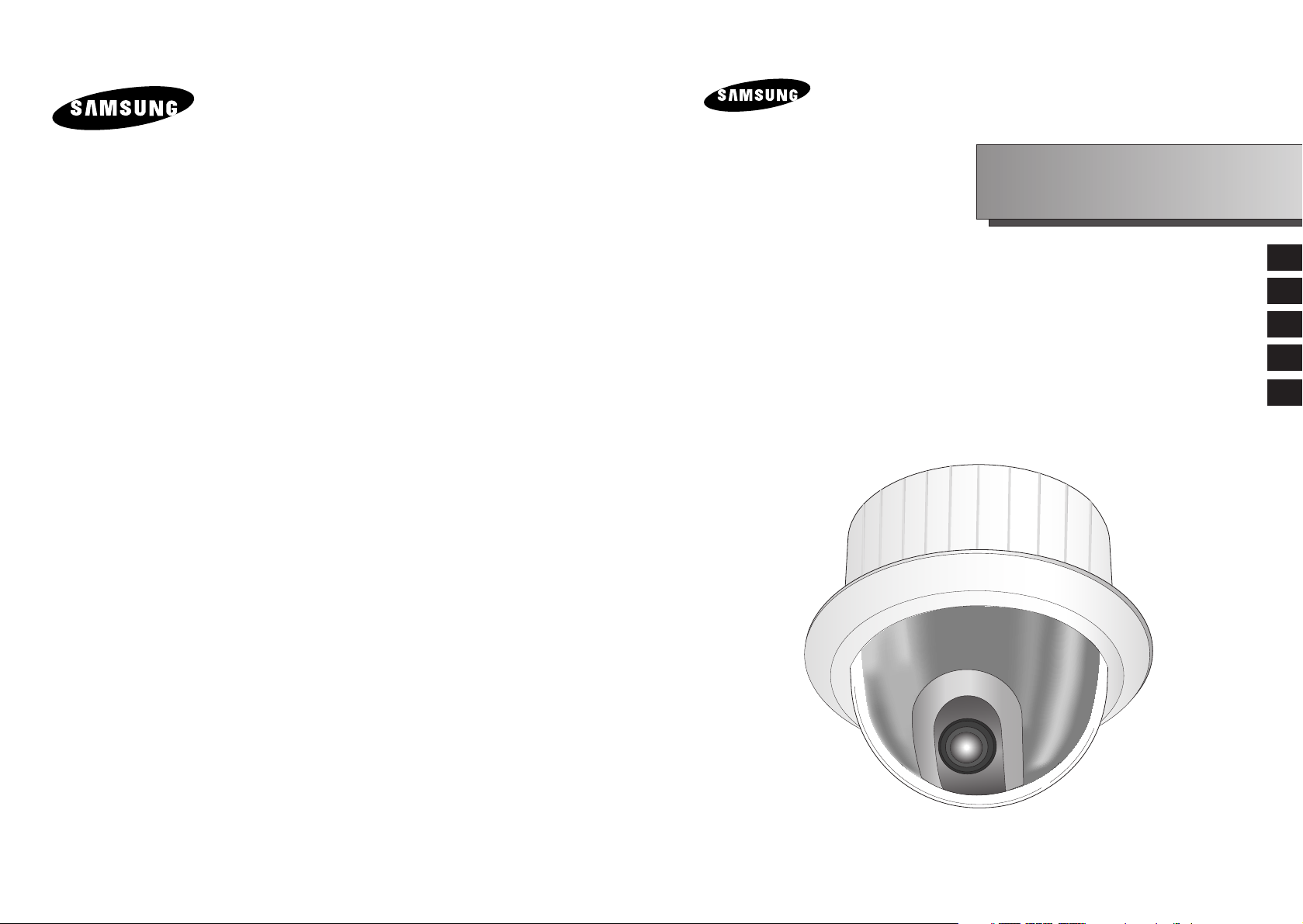
IP SmartDome Camera
Owner’s Instructions
Benutzerhandbuch
Manuel d’instruction
Manual del usuario
Istruzioni per l’uso

E
Important Safety Instructions
Safety Precautions
The purpose of this information is to ensure proper use of this product to
prevent danger or damage to property. Please be sure to observe all
precautions.
* The precautions are divided into "Warnings" and "Cautions" as
distinguished below:
Warning: Ignoring this warning may result in death or serious injury.
Caution: Ignoring this caution may result in injury or damage to property.
Warning instructions alert you to
a potential risk of death
or serious injury.
Caution instructions alert you to the
potential risk of injury or
damage to property.
Warning
1. Be sure to use only the standard adapter which is specified in the
specification sheet.
Using any other adapter could cause fire, electrical shock, or damage to
the product.
2. When connecting the power supply and signal wires, check the external
connection terminals before connecting them. Connect the alarm signal
wires to the alarm terminals, the AC adapter to the AC power input
receptacle, and the DC adapter to the DC power input, making sure that
the correct polarity is observed.
(Connecting the power supply incorrectly may cause fire, electrical shock,
or damage to the product.)
3. Do not connect multiple cameras to a single adapter.
(Exceeding the capacity may cause abnormal heat generation or fire.)
(A falling camera may cause personal injury.)
4. Securely plug the power cord into the power receptacle.
(Insecure connection may cause fire.)
5. When installing the camera on a wall or ceiling, fasten it securely and
firmly. (A falling camera may cause personal injury.)
1. Read these instructions.
2. Keep these instructions.
3. Heed all warnings.
4. Follow all instructions.
5. Do not use this apparatus near water.
6. Clean only with dry cloth.
7. Do not block any ventilation openings, Install in accordance with the
manufacturer's instructions.
8. Do not install near any heat sources such as radiators, heat registers, or
other apparatus (including amplifiers) that produce heat.
9. Do not defeat the safety purpose of the polarized or grounding- type plug.
A polarized plug has two blades with one wider than the other.
A grounding type plug has two blades and a third grounding prong.
The wide blade or the third prong are provided for your safety. If the
provided plug does not fit into your outlet, consult an electrician for
replacement of the obsolete outlet.
10. Protect the power cord from being walked on or pinched particularly at
plugs, convenience receptacles, and the point where they exit from the
apparatus.
11. Only use attachments/accessories specified by the manufacturer.
12. Use only with cart, stand, tripod, bracket, or table specified by the
manufacturer, or sold with the apparatus.
13. Unplug this apparatus. When a cart is used, use caution when moving the
cart/apparatus combination to avoid injury from tip-over.
14. Refer all servicing to qualified service personnel. Servicing is required
when the apparatus has been damaged in any way, such as power-supply
cord or plug is damaged, liquid has been spilled or objects have fallen into
the apparatus the apparatus has been exposed to rain or moisture, does
not operate normally, or has been dropped.

E
6. Do not place conductive objects (e.g., screwdrivers, coins, and metal
things) or containers filled with water on top of the camera. (Doing so may
cause personal injury due to fire, electrical shock, or falling objects.)
7. Do not install the unit in humid, dusty, or sooty locations.
(Doing so may cause fire or electrical shock.)
8. If any unusual smells or smoke come from the unit, stop using the product.
In such case, immediately disconnect the power source and contact the
service center. (Continued use in such a condition may cause fire or
electrical shock.)
9. If this product fails to operate normally, contact the store of purchase or
your nearest service center. Never disassemble or modify this product in
any way. (SAMSUNG is not liable for problems caused by unauthorized
modifications or attempted repair.)
10. When cleaning, do not spray water directly onto parts of the product.
(Doing so may cause fire or electrical shock.)
Wipe the surface with a dry cloth. Never use detergents or chemical
cleaners on the product, as this may result in discoloration of surface or
cause damage to the finish.
Caution
1. Do not drop objects on the product or apply strong shock to it. Keep away
from a location subject to excessive vibration or magnetic interference.
2. Do not install in a location subject to high temperature (over
122
°F
), low
temperature (below 14°F
), or high humidity.
(Doing so may cause fire or electrical shock.)
3. Avoid a location which is exposed to direct sunlight, or near heat sources
such as heaters or radiators.
(Neglecting to do so may result in a risk of fire.)
4. If you want to relocate the already installed product, be sure to turn off the
power and then move or reinstall it.
5. Install in a well-ventilated location.
6. Remove the power plug from the outlet when there is a lightning storm.
(Neglecting to do so may cause fire or damage to the product.)
FCC STATEMENT
This device complies with Part 15 of the FCC Rules. Operation is subject to
the following two conditions:
(1) This device may not cause harmful interference, and
(2) This device must accept any interference received, including interference
that may cause undesired operation.
Note: This equipment has been tested and found to comply with the limits for
a Class A digital device, pursuant to part 15 of the FCC Rules. These
limits are designed to provide reasonable protection against harmful
interference when the equipment is operated in a commercial
environment. This equipment generates, uses, and can radiate radio
frequency energy and, if not installed and used in accordance with the
instruction manual, may cause harmful interference to radio
communications. Operation of this equipment in a residential area is
likely to cause harmful interference in which case the user will be
required to correct the interference at his own expense.

1-2
E
1-1
Before Usage
This is a basic instruction manual for the SCC-C6475(P) user.
It contains all the instructions needed to use the SCC-C6475(P)
from a simple introduction of the control locations and functions of
the SCC-C6475(P) to installation methods in the set up menu.
We recommend all users of the SCC-C6475(P) from the
advanced user who has used similar cameras before to the
general user to read the instruction manual before using.
The most frequently used feature in the SCC-C6475(P) would be
the SCC-C6475(P) Setup Menu.
The SCC-C6475(P) Setup Menu is explained in detailed in
"Chapter 3 Setup Menu Overview".
The instructional manual is best used when read from beginning
to end, but for users wanting to read only the part they need here
are the Chapter summaries.
"Chapter 1 SCC-C6475(P) Overview" includes a brief
introduction of the SCC-C6475(P), part names and functions, and
Switch Settings.
"Chapter 2 SCC-C6475(P) Installation" explains the installation
procedures of the SCC-C6475(P) and provides preparation and
installation environment requirements.
"Chapter 3 Setup Menu Overview" presents the structure of the
Setup menu for the SCC-C6475(P) including a detailed
explanation of the functions performed in each submenu.
We will check how to use the 3 ip routers such as Linksys (Model:
WRT54G), Netgear (Model: RP614v2), D-Link (Model: DI-624+)
in the “appendix: Installation of IP router”.
"Appendix SCC-C6475(P) Product Specifications" contains
product specifications of the SCC-C6475(P) in itemized
categories.

1-4
E
1-3
❖ Layout.........................................................................................3-44
- Overlay Image ..........................................................................3-44
- Overlay Text .............................................................................3-46
- Screen Look .............................................................................3-47
- View HTML Code .....................................................................3-48
❖ Alarm ..........................................................................................3-49
- Transfer Setup..........................................................................3-49
- Alarm Setup..............................................................................3-50
- I/O Port .....................................................................................3-52
❖ Network.......................................................................................3-54
- Network ...................................................................................3-54
- IP Notification ...........................................................................3-56
6. Network Terms Definition................................................................3-57
Chapter 4 Setup Menu Overview
........................................................................4-1
Structure of the Setup Menu ................................................................4-2
1. CAMERA SET .................................................................................4-4
- CAMERA ID ...................................................................................4-4
- V-SYNC..........................................................................................4-5
- COLOR/BW....................................................................................4-6
- MOTION DET.................................................................................4-7
- ZOOM SPEED ...............................................................................4-8
- DIGITAL ZOOM..............................................................................4-8
- EXIT ...............................................................................................4-8
2. VIDEO SET .....................................................................................4-9
- IRIS ................................................................................................4-9
- ALC ................................................................................................4-9
- BLC ................................................................................................4-9
- WDR...............................................................................................4-9
- SHUTTER ....................................................................................4-10
- AGC..............................................................................................4-11
- MOTION.......................................................................................4-11
- WHITE BAL..................................................................................4-12
- DIS ...............................................................................................4-13
- FOCUS MODE.............................................................................4-14
- SPECIAL ......................................................................................4-14
- EXIT .............................................................................................4-14
3. PRESET .........................................................................................4-15
- POSITION SET ............................................................................4-16
- PRESET ID ..................................................................................4-16
- VIDEO SET ..................................................................................4-16
- PRESET SPEED..........................................................................4-16
- DWELL TIME ...............................................................................4-16
- IMAGE HOLD...............................................................................4-16
- EXIT .............................................................................................4-16
Before Usage.........................................................................................................1-1
Chapter 1 SCC-C6475(P) Overview
....................................................................1-6
SCC-C6475(P) Introduction .................................................................1-7
Locations of Control .............................................................................1-8
Camera Main Body...............................................................................1-8
Camera Holder.....................................................................................1-9
ADAPTER CONNECTION .................................................................1-10
INITIAL SETTING...............................................................................1-11
Setting RS-422A/RS-485 termination.................................................1-12
Factory Default...................................................................................1-13
Chapter 2 SCC-C6475(P) Installation
.................................................................2-1
Before Installing....................................................................................2-2
Preparing the Cables............................................................................2-3
Cable Connection.................................................................................2-4
Installing SCC-C6475(P)......................................................................2-5
Installing the Camera ...........................................................................2-8
Chapter 3 Network Manual Overview
................................................................3-1
1. Connecting SCC-C6475(P) Network................................................3-2
2. Setting the IP..................................................................................3-22
3. Log In. ............................................................................................3-23
4. Main Screen. ..................................................................................3-24
❖ Title bar and the upper menu......................................................3-24
❖ Viewer Screen ............................................................................3-25
❖ Logo and Video Format ..............................................................3-25
❖ Choice of camera and channel...................................................3-26
❖ Screen Size/Alarm/Banner window display
....................................3-27
❖ Screencapture/record/play
.............................................................3-28
❖ Image screen adjustment. ..........................................................3-29
5. Setting and Changing the function .................................................3-30
❖ Setting the basic function............................................................3-30
- Video ........................................................................................3-30
- IP ..............................................................................................3-32
- User..........................................................................................3-34
- Camera.....................................................................................3-35
- Language..................................................................................3-36
- Preset .......................................................................................3-36
❖ Setting the system ......................................................................3-37
- Status .......................................................................................3-37
- Date/Time.................................................................................3-38
- IP Filter .....................................................................................3-39
- Log............................................................................................3-40
- Software Update.......................................................................3-41
- Reset ........................................................................................3-42
- Parameter.................................................................................3-43
Table of contents

1-6
E
1-5
In this chapter we will briefly introduce the SCC-C6475(P) and
show main functions, locations of control and Switch Setting.
Chapter 1 SCC-C6475(P) Overview
4. ZONE SET .....................................................................................4-17
- PRIVACY ZONE...........................................................................4-17
- STYLE..........................................................................................4-17
- BLANK ALL ABOVE.....................................................................4-18
- BLANK ALL BELOW ....................................................................4-18
- PRYVACY ZONE MAP3 ..............................................................4-18
- SET ZONE AREA.........................................................................4-19
- SET ZOOM...................................................................................4-20
- REVERSE ....................................................................................4-20
- EXIT .............................................................................................4-20
- ZONE DIR SET/ZONE AREA SET ..............................................4-20
- ZONE DIR SET ............................................................................4-21
- ZONE AREA.................................................................................4-21
- LOCATION...................................................................................4-22
- ZONE ID SET...............................................................................4-22
- ZONE ENABLE ............................................................................4-22
5. AUTO SET .....................................................................................4-23
- AUTO PAN...................................................................................4-23
- START SET..................................................................................4-23
- END SET......................................................................................4-23
- DIRECTION..................................................................................4-24
- ENDLESS.....................................................................................4-24
- SPEED .........................................................................................4-24
- DWELL TIME ...............................................................................4-24
- PATTERN.....................................................................................4-24
- SCAN ...........................................................................................4-25
- AUTO PLAY .................................................................................4-26
- AUTO RETURN ...........................................................................4-26
- PLAY NUMBER............................................................................4-26
6. ALARM SET...................................................................................4-27
- ALARM PRIORITY SET...............................................................4-27
- ALARM IN SET ............................................................................4-27
- ALARM OUT SET ........................................................................4-27
- AUTO SET ...................................................................................4-28
- AUX OUT CONTROL...................................................................4-28
7. OTHER SET...................................................................................4-28
- PROPORTINAL P/T.....................................................................4-28
- TURBO P/T ..................................................................................4-29
- AUTO CAL ...................................................................................4-29
- D-FLIP..........................................................................................4-29
- CAM RESET ................................................................................4-29
- LANGUAGE .................................................................................4-29
- PASSWORD ................................................................................4-29
8. SYSTEM INFO...............................................................................4-30
9. SHORT KEYS ................................................................................4-31
Appendix.................................................................................................................5-1
Installing the IP router ........................................................................................5-2
Product specifications......................................................................................5-18
1-8
E
1-7
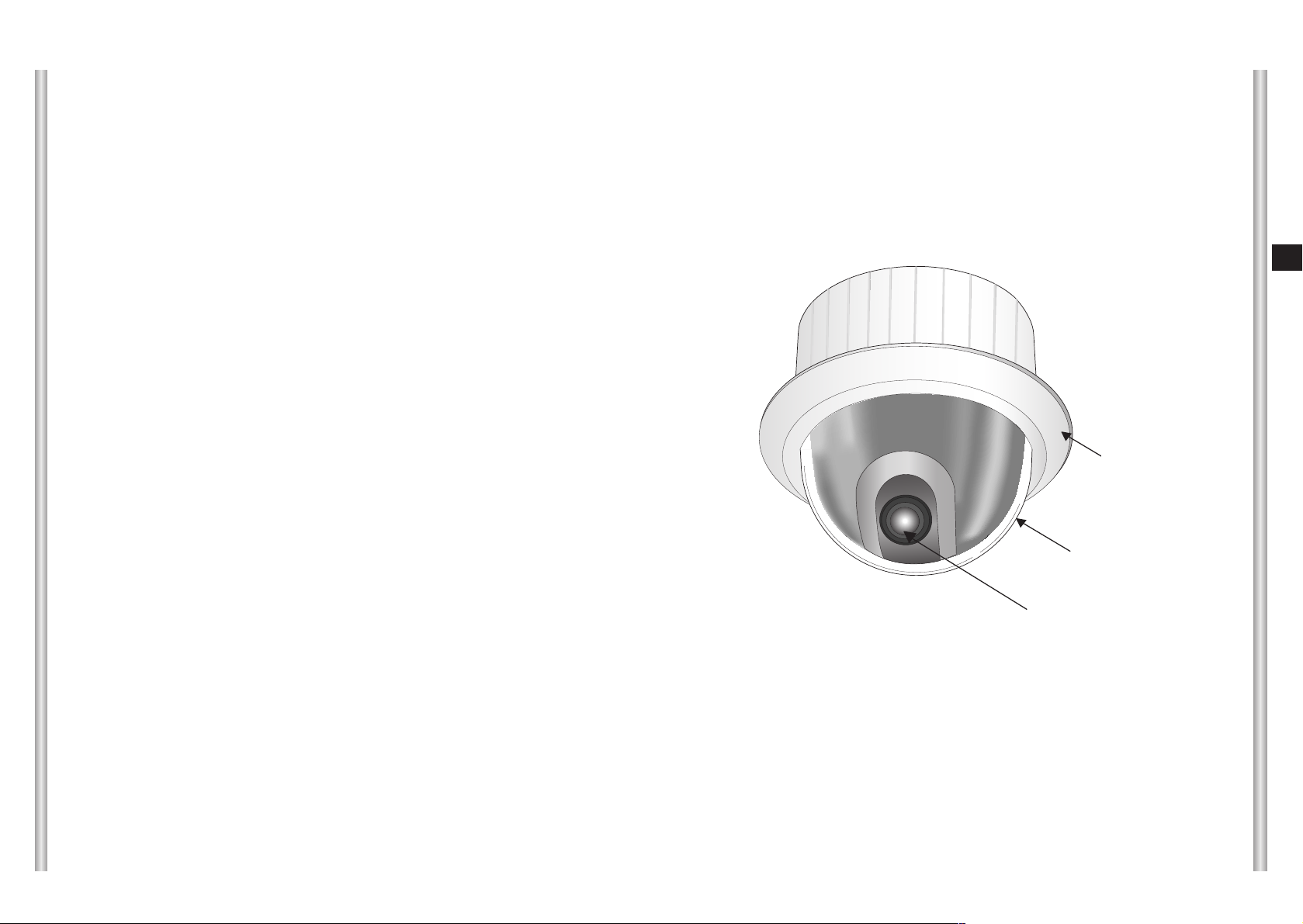
Locations of Control
Camera Body
Lense part
Dome cover
Cover body
SCC-C6475(P) Introduction
SCC-C6475(P) is a zoom lens built in smart dome camera which
provides you with the best monitoring function in connection with
CCTV at banks or companies.
The SCC-C6475(P) is a high quality surveillance camera using x22
zoom lens and digital zoom IC, it can catch clear images up to 220
times.
SCC-C6475(P) has a variety of functions such as;
- WDR to cover the full screen irregardless of its brightness,
- COLOR/BW to improve the sensitivity by automatic conversion
into the black and white mode at night or in the environment with
low illumination,
- White Balance to control the brightness to the illumination,
- Backlight Compensation under spotlight or utmost bright
illumination,
- Auto Focus to automatically adjust the focus to the subject
movement,
- Privacy zone to hide a specific area for personal privacy, and,
- PAN/TILT for precise control at high speed.
The SCC-C6475(P) uses an Alarm function for alert situations and
moving camera in the direction you want, ZOOM-IN and
ZOOM-OUT functions can be remote controlled.

ON
SEE INSTRUCTION MANUAL
SW704
12345678
(x100)
SW701 SW702 SW703
(x10) (x1)
1-10
E
1-9
ADAPTER CONNECTION
SCC-C6475(P) Adapter BOARD
Camera Holder
Power Connection Terminal
Power Indicator
Video Output Terminal
ALARM IN
ALARM OUT
Factory Default Button
MAC Address Label
NETWORK Cable
Connection Terminal
RS-232 Cable
Connection Terminal
Remote controller
Connection Terminal
1-12
E
1-11
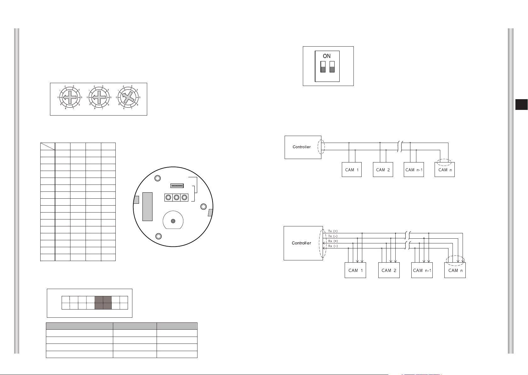
Setting RS-422A/RS-485 termination
12
As it is shown in the structure map, when Controller and RS-422A/RS485 is connected it should be terminated according to the Cable feature
of impedance on the each end of the transmitting line to transfer the
signals in long distance by controlling the reflection of the signals to the
lowest.
<RS-485 Half Duplex Organization>
n < 32
Termination
SW1-ON
Division
Termination: using numbers 1 and 2 PIN, turn to ON and it will be terminated.
<RS-422A/RS-485 Full Duplex Organization>
Division
Division
SW1-ON
SW2-ON
n < 32
INITIAL SETTING
CAMERA ADDRESS SETUP
Use SW701, SW702, or 703 for Camera Address setup. You may allocate
up to 255 addresses by using SW701 to set the 3rd digit, SW702 the 2nd
digit, and SW703 the 1st digit.
EX) In case of Camera Address 1, see the following figure for setup.
Setting communication Protocol
Use number 1~4 PIN of SW704 to set communication Protocol.
Baud Rate Setting
Use PIN 5 and 6 of SW704.
SW701
SW702
SW703
1 2 3 4 5 6 7 8
ON
OFF
BAUD RATE
4800 BPS
9600 BPS
19200 BPS
38400 BPS
PIN 5
ON
OFF
ON
OFF
PIN 6
ON
ON
OFF
OFF
A : SAMSUNG HALF
B : SAMSUNG FULL
PIN1 PIN2 PIN3 PIN4
A OFF OFF OFF OFF
B ON OFF OFF OFF
C OFF ON OFF OFF
D ON ON OFF OFF
E OFF OFF ON OFF
F ON OFF ON OFF
G OFF ON ON OFF
H ON ON ON OFF
I OFF OFF OFF ON
J ON OFF OFF ON
K OFF ON OFF ON
L ON ON OFF ON
M OFF OFF ON ON
N ON OFF ON ON
O OFF ON ON ON
PONONONON
PIN
Comp
(x100) (x10) (x1)
SW704
ON
1 2 3 4 5 6 7 8
SW701 SW702 SW703
SEE INSTRUCTION MANUAL
(BOTTOM VIEW)
SW 704

2-1
E
1-13
In this chapter, we will check the contents of the package before
installing the SCC-C6475(P), and prepare a power adapter suitable
for the power supply system.
(Power Consumption: 25W; Voltage: AC24V, 1.5A)
Then, we will install the SCC-C6475(P) and connect the cables.
Chapter 2 SCC-C6475(P) Installation
Factory Default
It recovers the whole setting of SCC-C6475(P) to the factory default.
There are two Factory Default methods as follows.
(1) Using the Factory Default in the Reset page
Refer to 5. Setting and changing the function (System - Reset) in
Chapter 3 Network menu Overview.
(2) Using the Factory Default button on the side of the unit.
Proceed as follows.
1. Turn the power off.
2. While pressing the Factory default button, turn the power on.
3. When the Status LED flickers 3 times in red, unpress the Factory
Default button.
4. If the Status LED turns to green, the whole setting of SCCC6475(P) recovers to the factory default.
CCCCaaaauuuuttttiiiioooonn
nn
After executing, the user can access only when executing the basic
network setting (IP Address, Subnet<RS-485 Half Duplex
configuration> Mask, Gateway) by using the IP installer.

To install and use the SCC-C6475(P), the following cables should be
prepared.
Power Adapter Cable
The cable that plugs into the SCC-C6475(P) power input receptacle has
the rated voltage of AC24V, 1.5A.
Check the rated voltage before using the cable.
Video Cable
The SCC-C6475(P)'s cable is a BNC Cable for connecting the videooutput terminal to the video-input terminal of the monitor.
Preparing the Cables
2-3
E
2-2
SCC-C6475(P)
Bracket anchor
Camera Holder
Adapter Board
Cover Body
Screws
Installation CD
RJ-45 CROSS LAN
CABLE
Before Installing
Checking Package Contents
Please check that all components listed below are included in the package:
Owner’s
Instructions
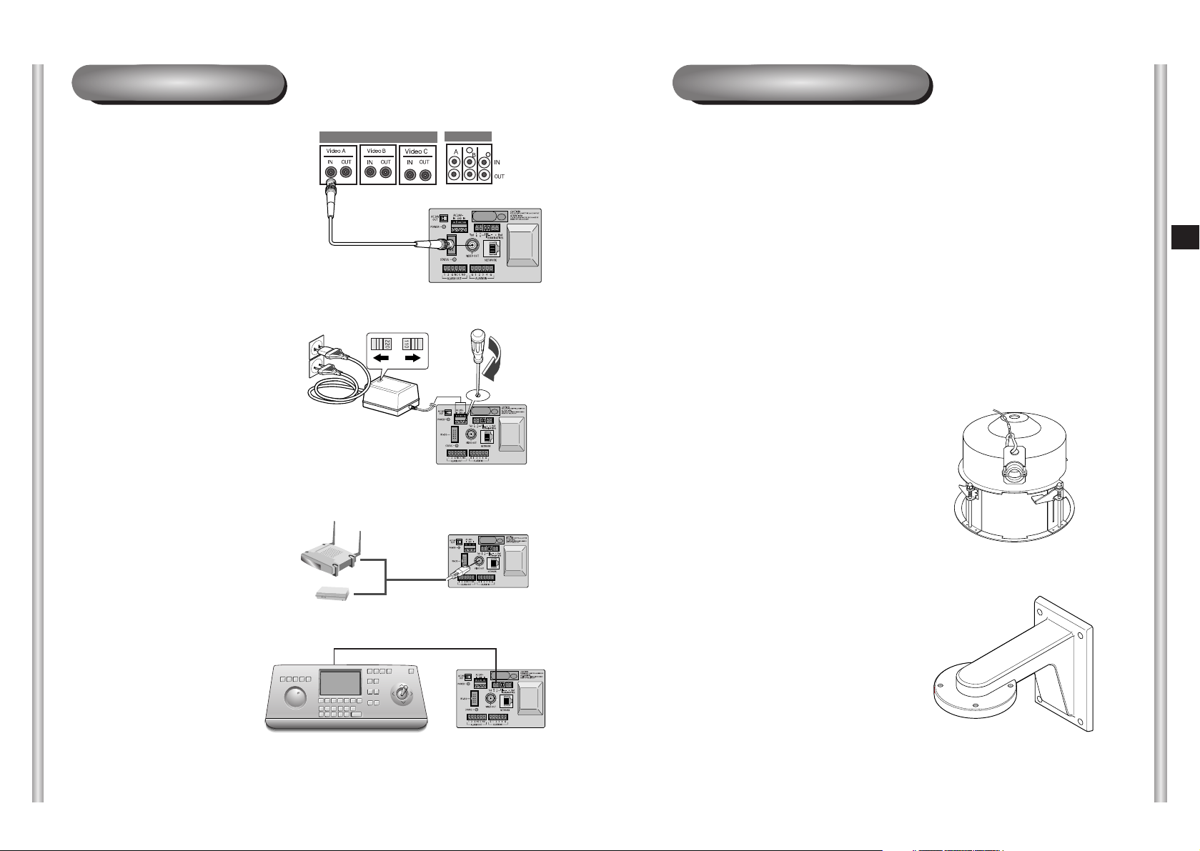
Installing SCC-C6475(P)
Installation Precautions
1) Make sure that the installation site can sufficiently support a minimum of
four times the net weight of the SCC-C6475(P) IP SmartDome Camera
and other accessories.
2) Install in an area where the space above the ceiling board is over 18 cm
(7 in.) high.
3) Use the supplied screws to fasten the camera to the bracket assembly.
4) Keep persons away from the installation area, as there is a risk of falling
objects.
Also, move valuables to a safe location before installation.
Separately Sold Products for Installation
Depending on the installation site, it may be convenient to use one of the
following products.
1) CEILING MOUNT BRACKET
(SBR-100DCM)
This bracket is used for installing
the IP SmartDome Camera in the
plenum above the drop ceiling.
2) WALL MOUNT ADAPTOR
(SADT-100WM)
This adaptor is used for installing the
indoor housing or the outdoor
housing for the IP SmartDome
Camera on a wall.
2-5
E
2-4
6. Connect the Remote Control
Terminal of the
SCC-C6475(P)
and the external Controller.
Controller
Adapter BOARD
1. First, connect one end of the
BNC video cable connector to
the Video Output Terminal
(VIDEO OUT)
2. Then, connect the other end of
the connector to the Video Input
Terminal of the monitor.
3. Adjust the power select switch
(110 V or 220 V) after verifying
the power to connect SCCC6475(P).
4. Connect the two adapter power
output cables to the power input
terminal of SCC-C6475(P) by
using the setting driver.
5. Connect the LAN cable to the IP
router or hub to the using
NETWORK connect terminal.
Cable Connection

5) CEILING MOUNT ADAPTOR (SADT-100CM)
This adaptor is used for installing the indoor housing or the outdoor
housing for the IP SmartDome Camera to a concrete ceiling.
6) POLE MOUNT ADAPTOR (SADT-100PM)
This adaptor is used for installing the WALL MOUNT ADAPTOR
(SADT-100WM) to a pole that is over 8 cm (2.76 in.) in diameter.
3) INDOOR HOUSING (SHG-120)
This housing is used for installing the IP SmartDome Camera to an
indoor wall or a ceiling.
4) OUTDOOR HOUSING (SHG-220)
This housing is used for installing the IP SmartDome Camera to an
outdoor wall or a ceiling.
2-7
E
2-6
2-9
E
2-8
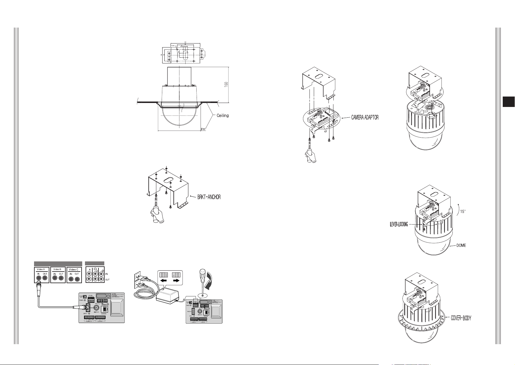
7. [Figure 7] Match the 3 holes on the
back of the CAMERA and the
CONNECTOR and turn it left about
15 degrees.
(Check the sound of LOCKING
and that the LEVER-LOCKING
is in place)
* Use the screws (BH M3 x L8) to
connect the CAMERA and the
ADAPTER so they don't move.
[Figure 7]
8. [Figure 8] Assemble the
COVER-BODY onto the DOME.
[Figure 8]
5. [Figure 5] Match the
Bracket anchor and CAMERA
ADAPTER and use 4screws
(PH M4 x 8) to assemble them.
[Figure 5]
6. Pull the safety wire from the case
body, and assembly it to the
camera holder.
[Figure 6]
3. [Figure 2] Assemble the
BRKT-ANCHOR on the ceiling
and screw the 4 bolts in.
[Figure 2]
2. Make a hole in the ceiling where the camera will be installed.
(The hole should be about ø185)
4. [Figure 3,4] Connect the various cables to the CAMERA ADAPTER.
(See page 2-4)
[Figure 4]
[Figure 3]
[Figure 1]
Length of
ceiling Hole
1. [Figure 1] Install the structure on the
ceiling.
(Refer to Installation reference
for the Length of the structure)
* Built in by the builder of the structure
Installing the Camera
3-2
E
3-1
In this chapter, we will check how to install the IP Setting of
SCC-C6475(P) and operate the camera connecting with network
by using the camera access program, and also check various
features and usage.
CCCCaaaauuuuttttiiiioooonn
nn
Smart Viewer for ProCam for Web-browser operates normally with
Microsoft Internet Explorer 5.0 and above. If the other browser is
used, some functions may operate abnormally.
Chapter 3. Network Manual Overview
1. Connecting SCC-C6475(P) Network
This chapter uses Linksys (WRT54G) IP router as an example to explain
this network connection. Please refer to the “IP router setting” to set the
competitor’s IP router model setting.
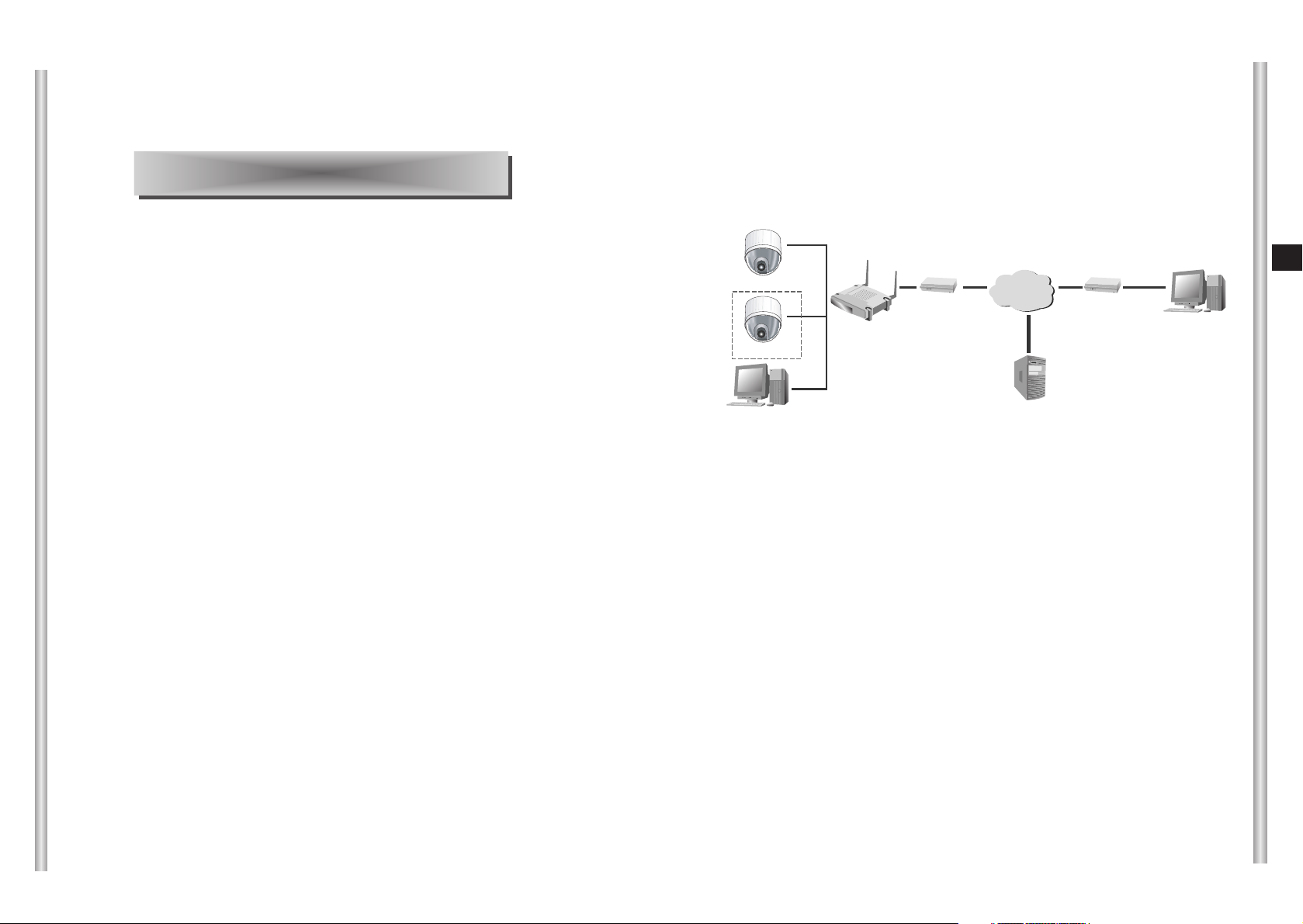
1) In case of using xDSL/Cable Internet network and IP router
■
If the user wants to use IP router to configure the network, he/she
should connect IP router to ADSL or Cable modem first, and set them in
the menu of IP router.
■
To access the setup menu of the IP router, enter the IP router access
address in the Local PC internet browser connected to the IP router.
(Example: http://192.168.1.1)
* Please assign the Local PC window network setting as the following
example.
Example) IP: 192.168.1.2
Subnet mask: 255.255.255.0
Gateway: 192.168.1.1
■
When accessing the IP router address, window to ask the password
appears. Do not enter anything in the User Name and enter the ‘admin’
in the password and press ‘OK’, the IP router setting page appears.
INTERNET
xDSL or Cable
Modem
xDSL or Cable
Modem
IP Router
SCC-C6475(1)
SCC-C6475(2)
Local PC
DDNS Server
(Data Center, KOREA)
External Remote PC
SCC-C6475(P)(2)
SCC-C6475(P)(1)
3-3 3-4
E
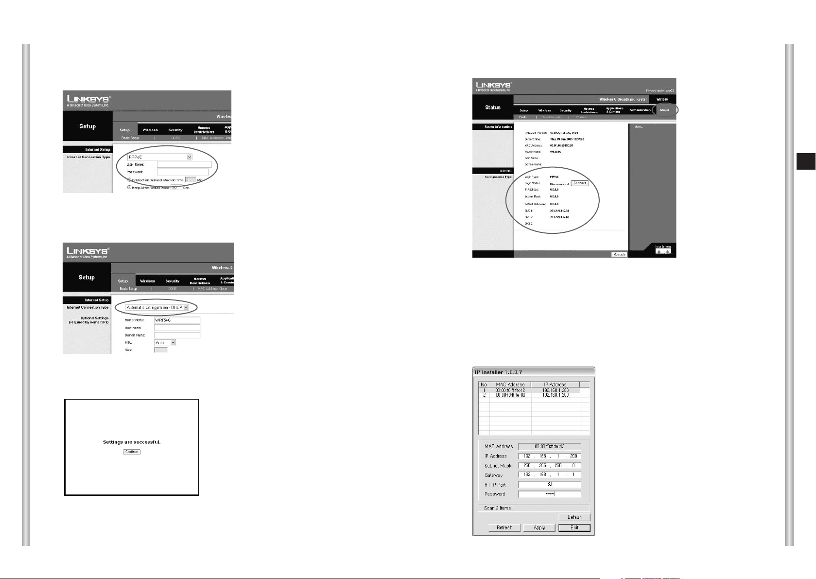
■
If the IP router is connected to xDSL modem, select ‘PPPoE’ in Setup
➞ Basic Setup as figure and enter the User Name and Password to
access the ISP (Internet Service Provider).
■
If the IP router is connected to the Cable modem, select ‘Automatic
Configuration-DHCP' in Setup ➞ Basic Setup as figure.
■
After finishing the setting, click the ‘Save settings’ button and save the
setting.
■
Check the ‘Status’ page to verify that xDSL or Cable modem is
connected successfully.
■
Execute IPinstaller.exe program in the user’s Local PC to set the
SCC-C6475(P) IP connected to the IP router.
If not, click the ‘Connect’ button to retry, or recheck the setting value and
retry.
If xDSL or Cable modem is connected successfully, IP, Subnet Mask,
Gateway from ISP will be indicated.

3-5
3-6
E
1. Execute the IP installer program and the MAC Address and IP Address list
of SCC-C6475(P) cameras connected to the IP router will be shown.
●
SCC-C6475(P) IP’s basic value is set as ‘192.168.1.200’ when
shipping.
●
MAC Address of each SCC-C6475(P) is indicated at the back of the
camera holder, please check when you sort the camera.
2. When selecting the camera that is desired to set in the camera list, the
selected camera IP, Subnet Mask, Gateway, HTTP Port in the information
window at the bottom of the list will be indicated as the basic value when it
was shipped.
3. Set the selected camera IP to the private IP scope that IP router provides.
(Example: 192.168.1.2~255)
4. Subnet Mask and Gateway should note and enter the IP router setting.
5. HTTP Port that Internet browser use to access is set 80 as a basic value,
but it can be changed as the user’s network configuration.
For example, more than 2 SCC-C6475(P) cameras are connected to an IP
router, HTTP Port of each camera should be set differently.
6. After completing every setup, enter the Password and click the Apply
button. And then SCC-C6475(P) will reboot automatically.
●
Password is the root user’s log in Password to access the
SCC-C6475(P).
●
Password is set as basic value ‘4321’ when it is shipped.
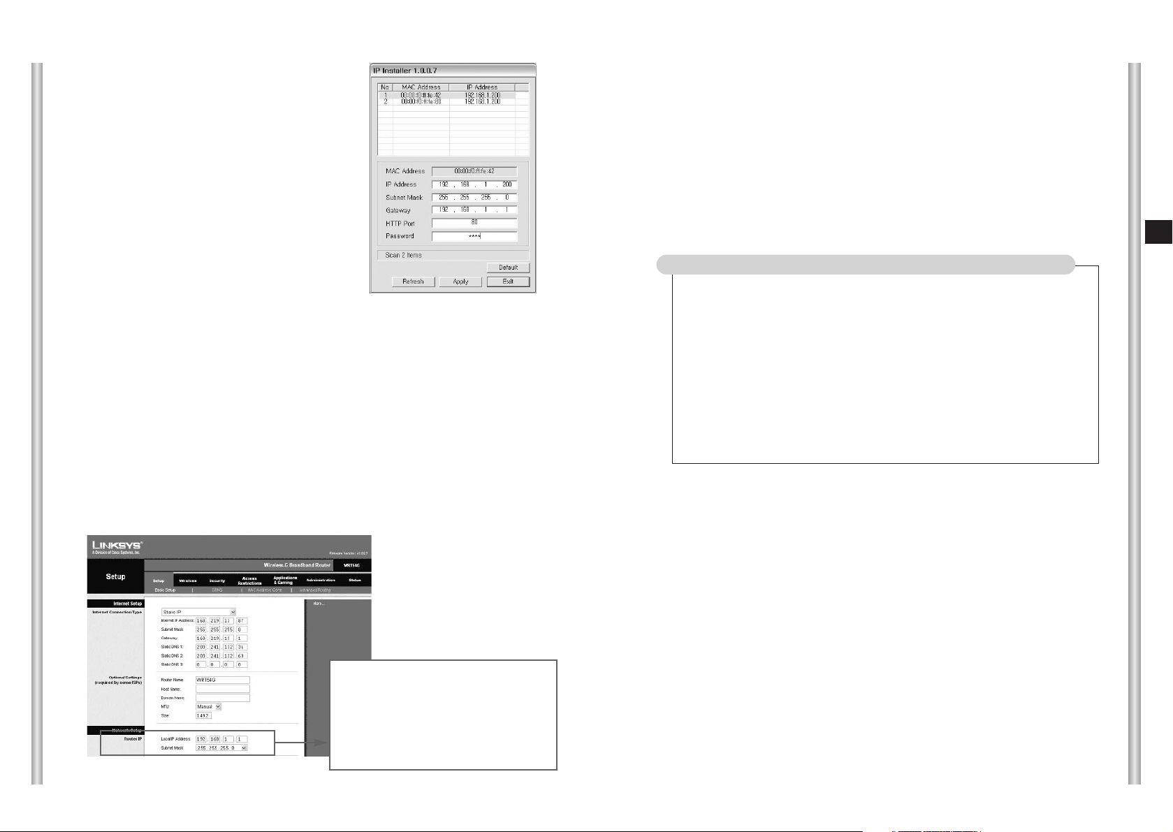
●
Setup ➞ Refer to the Local IP
Address and Subnet Mask of the
Router IP in the Network Setup at
the Basic Setup.
●
Local IP Address becomes the
SCC-C6475(P) Gateway value.
■
After completing the setup as above, user executes the internet
browser in the Local PC and access SCC-C6475(P).
If the camera that HTTP Port is set to other numbers except 80, user
should enter the Port number at browser address window together to
access.
Example) http://192.168.1.201:81
■
Accessing SCC-C6475(P) by using the internet browser, Log In page
as follow appears.
- User ID to Log In is set to a basic value ‘root’ when it was shipped and
the password is ‘4321’.
In case of connecting more than 2 cameras to one IP router
1.Set the SCC-C6475(P) IP and HTTP Port differently.
Example) No.1 SCC-C6475(P) -IP: 192.168.1.200
Subnet Mask: 255.255.255.0
Gateway: 192.168.1.1
HTTP Port: 80
No.2 SCC-C6475(P) - IP: 192.168.1.201
Subnet Mask: 255.255.255.0
Gateway: 192.168.1.1
HTTP Port: 81
3-8
E
3-7
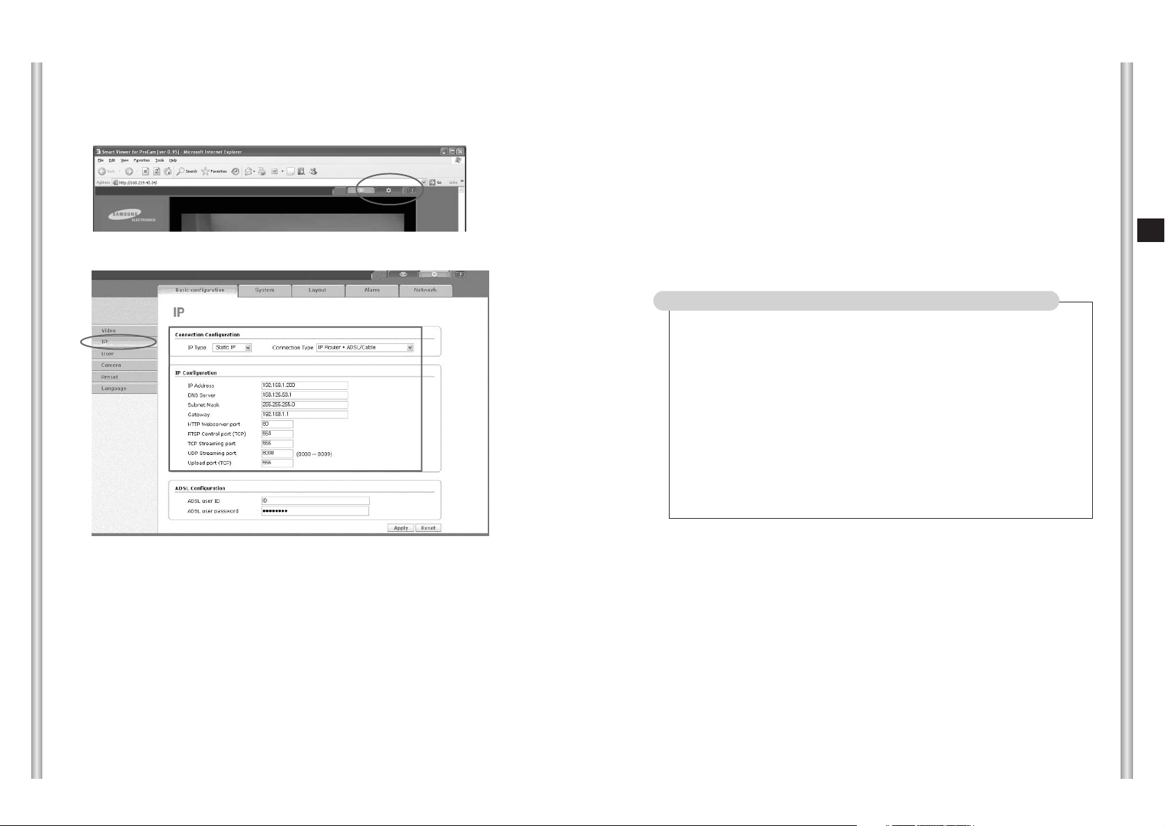
■
Log in at SCC-C6475(P) and the main screen that user can see images
appears.
■
After checking if the camera image works well, click the setup mode button
in the right up side of the main screen.
■
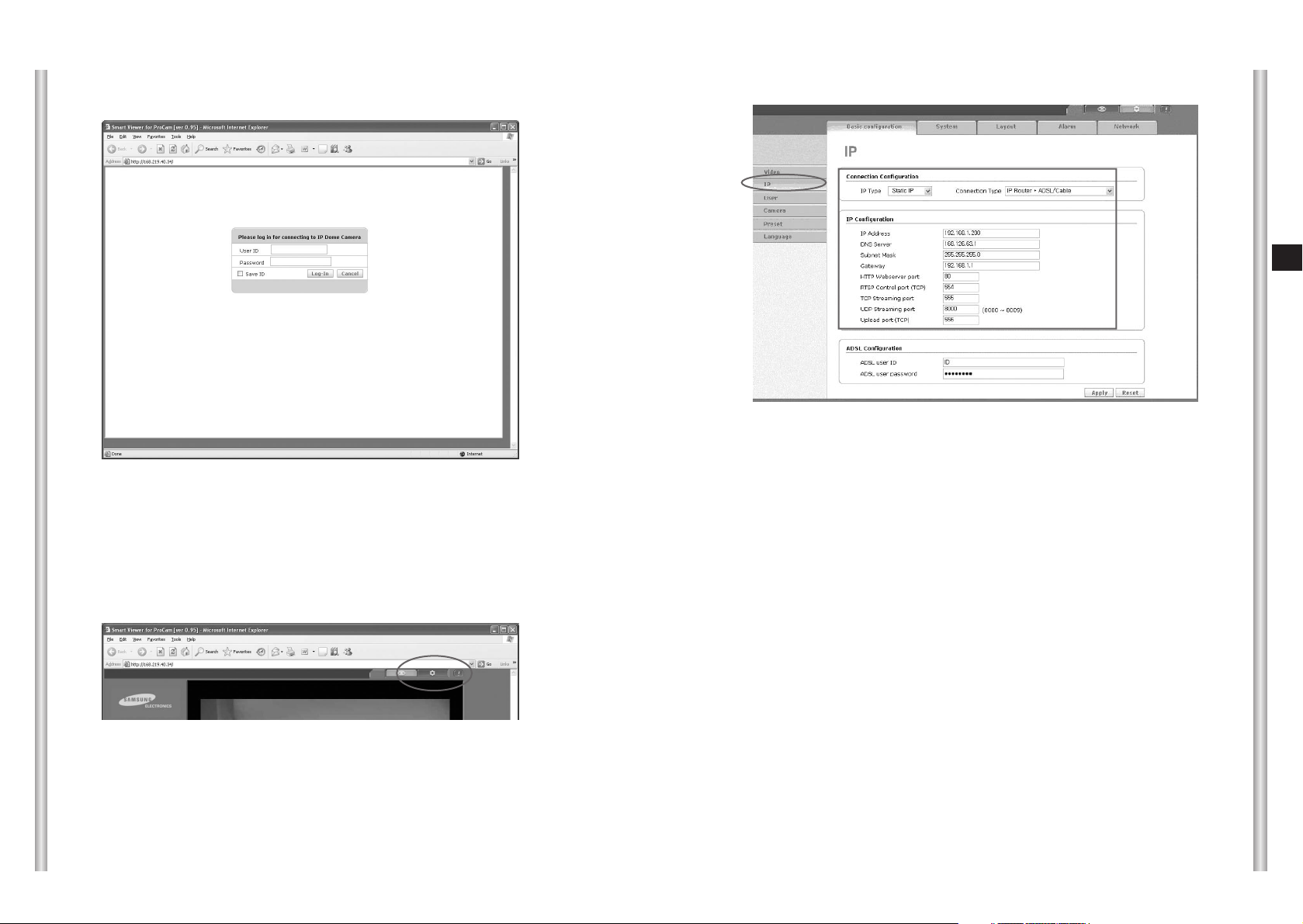
Move the SCC-C6475(P) setup mode to the Basic Configuration ➞ IP page.
■
Check if the setting value that user has entered the setting value by using the
IP Installer program in the IP Configuration item is saved safely.
- DNS Server setting is assigned as the basic value '168.126.63.1'. User can
change the setting value when needed.
■
Assign IP Type as ‘Static IP’ in the Connection Configuration, and assign
Connection Type as 'IP Router + ADSL/Cable'.
- In case that the Connection Configuration is not set for the user’s network
environment, the access cannot be done or the image cannot be appeared
smoothly.
■
Set RTSP Control port, TCP Streaming port, UDP Streaming port, and
Upload port. Each port is the access port that SCC-C6475(P) network
program is using, in case that several SCC-C6475(P) is connected to
one IP router, SCC-C6475(P) port should be set differently.
●
RTSP Control port: Port to control the image sending. The basic
value is set 554(TCP).
●
TCP Streaming port: Port to send the image by using the TCP
process. The basic value is set 555 (TCP).
●
UDP Streaming port : Port to send the image by using the UDP
process. The basic value is set
8000~8009(UCP).
●
Upload port: Port to upgrade S/W. The basic value is set 556(TCP).
In case of connecting more than 2 cameras to an IP router
1. Set each SCC-C6475(P) Port differently.
Example) No.1 SCC-C6475(P) – RTSP Control port: 554
TCP Streaming port: 555
UDP Streaming port: 8000
(8000~8009)
Upload port: 556
No.2 SCC-C6475(P) – RTSP Control port: 557
TCP Streaming port: 558
UDP Streaming port: 8010
(8010~8019)
Upload port: 559
■
After completing every setup, Click the Apply button.
- SCC-C6475(P) will be reboot if the IP-related setting is changed
■
Finally, set the Port Forwarding in order for IP router to handle the
access requirement about the assigned IP to each SCC-C6475(P)
camera.
3-10
E
3-9
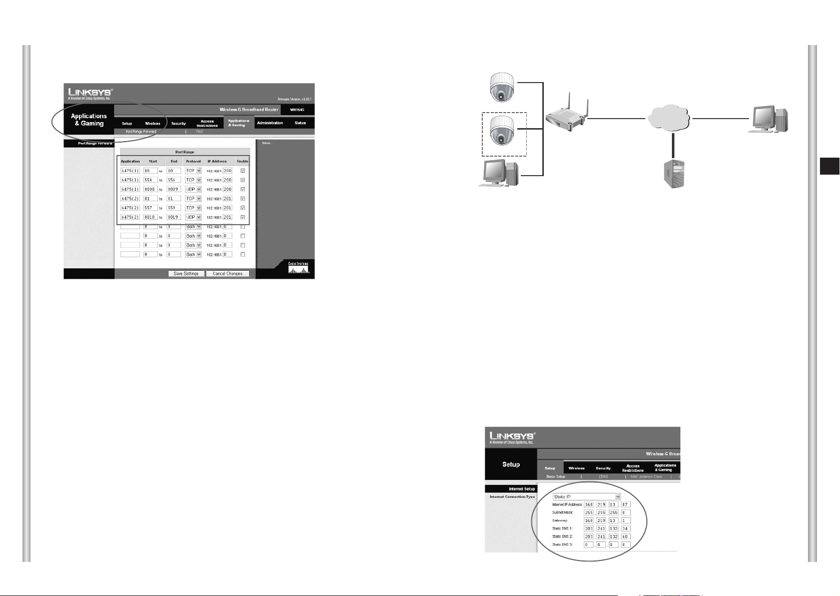
■
IP router Port Forwarding setting can be designated at the Application &
Gaming ➞ Port Range Forward page.
■
As the Example in the figure, designate the TCP and UDP Port to the
SCC-C6475(P) camera that is connected to the IP router.
Each port that is set to the IP router should be set to the Port number that is
set at the SCC-C6475(P) IP setup page.
■
After completing the Port Forwarding setting to the SCC-C6475(P), Click the
Save Settings and save the setting value.
■
Completing the above setting, User can access the SCC-C6475(P) and
monitor the monitoring image by using the Local PC connected to the IP
router and also monitor the image to access the external IP router Remote
PC.
- In case of accessing in the Local PC, user can access it by using the
private IP (Example: 192.168.1.200) designated to SCC-C6475(P).
- IP or DDNS address of the IP router in case of accessing in the External
Remote PC. Access using (Example: cfffe42.websamsung.net).
■
DDNS Address is composed of 6 figures at the end of SCC-C6475(P) MAC
Address, Alphabet 'c', and the combination of domain name
“websamsung.net”.
Example) If the MAC Address of SCC-C6475(P) is 00:00:f0:ff:fe:42,
DDNS Address = c + fffe42 + websamsung.net =
cfffe42.websamsung.net
■
If the user use the IP router and configure network in the LAN environment,
set in the menu of the IP router.
■
To access the setup menu of the IP router, enter the IP router access
address in the Local PC internet browser connected to the IP router.
(Example: http://192.168.1.1)
- Please assign the Local PC window network setting as the following
example.
Example) IP: 192.168.1.2
Subnet mask: 255.255.255.0
Gateway: 192.168.1.1
■
When accessing the IP router address, window to ask the password
appears. Do not enter anything in the User Name and enter the ‘admin’ in
the password and press ‘OK’, the IP router setting page appears.
■
Select ‘Static IP’ in the Setup ➞ Basic Setup as figure, enter the valid IP
and Subnet Mask, Gateway, DNS that is possible to connect the internet.
Contact the Network manager about the setting value.
2) In case of using the LAN and IP router
INTERNET
LAN
IP Router
SCC-C6475(1)
SCC-C6475(2)
Local PC
DDNS Server
(Data Center, KOREA)
External Remote PC
SCC-C6475(P)(1)
SCC-C6475(P)(2)
3-12
E
3-11
■
Execute IPinstaller.exe program in the
user’s Local PC to set the SCC-C6475(P)
IP connected to the IP router.
1. Execute the IP installer program and the MAC Address and IP Address list
of SCC-C6475(P) cameras connected to the IP router will be shown.
●
SCC-C6475(P) IP’s basic value is set as ‘192.168.1.200’ when shipping.
●
MAC Address of each SCC-C6475(P) is indicated at the back of the
camera holder, please check when you sort the camera.
2. When selecting the camera that is desired to set in the camera list, the
selected camera IP, Subnet Mask, Gateway, HTTP Port in the information
window at the bottom of the list will be indicated as the basic value when it
was shipped.
3. Set the selected camera IP to the private IP scope that IP router provides.
(Example: 192.168.1.2~255)
4. Subnet Mask and Gateway should note and enter the IP router setting.
●
Setup ➞ Refer to the Local IP
Address and Subnet Mask of the
Router IP in the Network Setup at
the Basic Setup.
●
Local IP Address becomes the
SCC-C6475(P) Gateway value.
5. HTTP Port that Internet browser use to access is set 80 as a basic value,
but it can be changed as the user’s network configuration.
For example, more than 2 SCC-C6475(P) cameras are connected to an IP
router, HTTP Port of each camera should be set differently.
6. After completing every setup, enter the Password and click the Apply
button. And then SCC-C6475(P) will reboot automatically.
●
Password is the root user’s log in Password to access the
SCC-C6475(P).
●
Password is set as basic value ‘4321’ when it is shipped.
■
After completing the setup as above, user executes the internet
browser in the Local PC and access SCC-C6475(P).
If the camera that HTTP Port is set to other numbers except 80, user
should enter the Port number at browser address window together to
access.
Example) http://192.168.1.201:81
In case of connecting more than 2 cameras to one IP router
1.Set the SCC-C6475(P) IP and HTTP Port differently.
Example) No.1 SCC-C6475(P) - IP: 192.168.1.200
Subnet Mask: 255.255.255.0
Gateway: 192.168.1.1
HTTP Port: 80
No.2 SCC-C6475(P) - IP: 192.168.1.201
Subnet Mask: 255.255.255.0
Gateway: 192.168.1.1
HTTP Port: 81
3-14
E
3-13
■
Accessing SCC-C6475(P) by using the internet browser, Log In page as
follow appears.
■
Log in at SCC-C6475(P) and the main screen that user can see images
appears.
■
After checking if the camera image works well, click the setup mode button
in the right up side of the main screen.
- User ID to Log In is set to a basic value ‘root’ when it was shipped and
the password is ‘4321’.
■
Move the SCC-C6475(P) setup mode to the Basic Configuration ➞IP page
.
■
Check if the setting value that user has entered the setting value by using
the IP Installer program in the IP Configuration item is saved safely.
- DNS Server setting is assigned as the basic value '168.126.63.1'. User
can change the setting value when needed.
■
Assign IP Type as ‘Static IP’ in the Connection Configuration, and assign
Connection Type as 'IP Router + LAN'.
- In case that the Connection Configuration is not set for the user’s
network environment, the access cannot be done or the image cannot
be appeared smoothly.
■
Set RTSP Control port, TCP Streaming port, UDP Streaming port, and
Upload port. Each port is the access port that SCC-C6475(P) network
program is using, in case that several SCC-C6475(P) is connected to one
IP router, SCC-C6475(P) port should be set differently.
●
RTSP Control port: Port to control the image sending. The basic value
is set 554(TCP).
●
TCP Streaming port: Port to send the image by using the TCP process.
The basic value is set 555 (TCP).
●
UDP Streaming port : Port to send the image by using the UDP
process. The basic value is set
8000~8009(UCP).
●
Upload port: Port to upgrade S/W. The basic value is set 556(TCP).
3-16
E
3-15
In case of connecting more than 2 cameras to an IP router
1. Set each SCC-C6475(P) Port differently.
Example) No.1 SCC-C6475(P) – RTSP Control port: 554
TCP Streaming port: 555
UDP Streaming port: 8000 (8000~8009)
Upload port: 556
No.2 SCC-C6475(P) – RTSP Control port: 557
TCP Streaming port: 558
UDP Streaming port: 8010 (8010~8019)
Upload port: 559
■
After completing every setup, Click the Apply button.
- SCC-C6475(P) will be reboot if the IP-related setting is changed
■
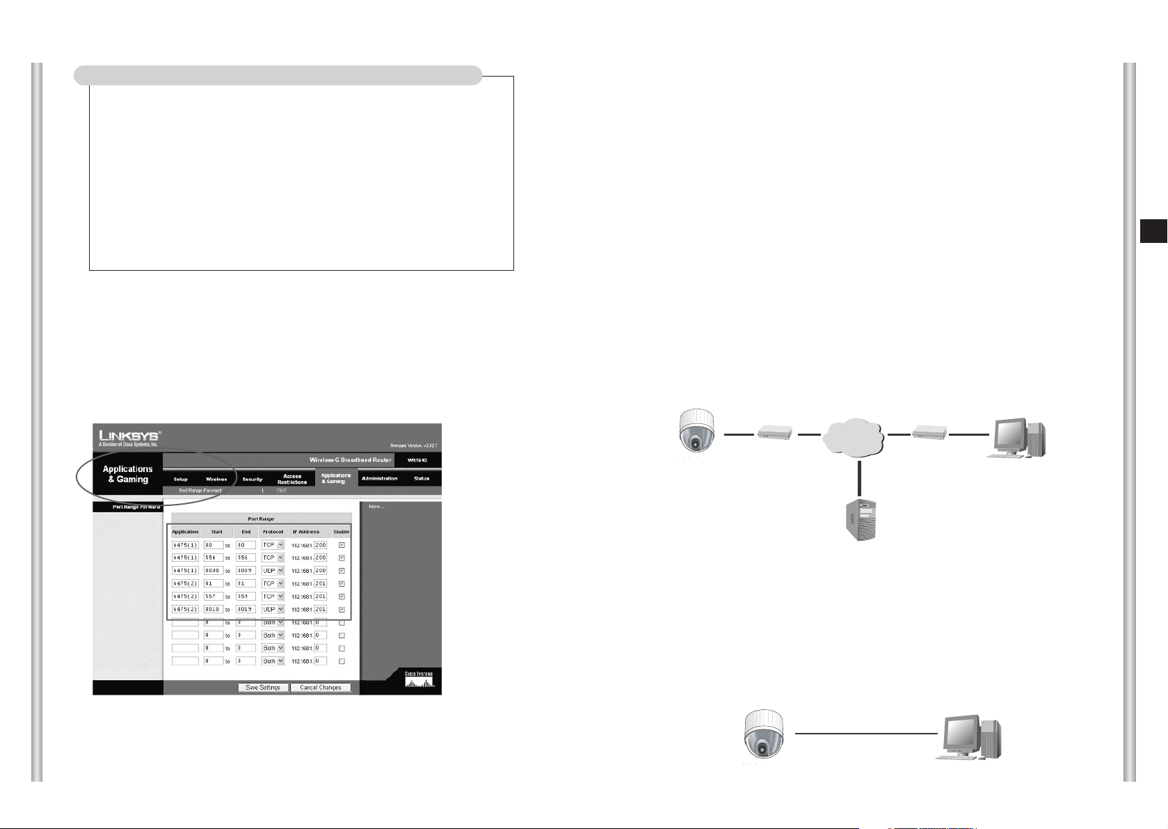
Finally, set the Port Forwarding in order for IP router to handle the access
requirement about the assigned IP to each SCC-C6475(P) camera.
■
IP router Port Forwarding setting can be designated at the Application &
Gaming ➞ Port Range Forward page.
■
As the Example in the figure, designate the TCP and UDP Port to the SCCC6475(P) camera that is connected to the IP router.
Each port that is set to the IP router should be set to the Port number that is
set at the SCC-C6475(P) IP setup page.
■
After completing the Port Forwarding setting to the SCC-C6475(P), Click
the Save Settings and save the setting value.
■
Completing the above setting, User can access the SCC-C6475(P) and
monitor the monitoring image by using the Local PC connected to the IP router
and also monitor the image to access the external IP router Remote PC.
- In case of accessing in the Local PC, user can access it by using the
private IP (Example: 192.168.1.200) designated to SCC-C6475(P).
- IP or DDNS address of the IP router in case of accessing in the
External Remote PC. Access using (Example:
cfffe42.websamsung.net).
■
DDNS Address is composed of 6 figures at the end of SCC-C6475(P)
MAC Address, Alphabet 'c', and the combination of domain name
“websamsung.net”.
Example) If the MAC Address of SCC-C6475(P) is 00:00:f0:ff:fe:42,
DDNS Address = c + fffe42 + websamsung.net =
cfffe42.websamsung.net
■
If the user connect the camera to the ADSL/Cable modem directly not
using the IP router, assign the network setting in the SCC-C6475(P)
IP setup page to ADSL or Cable Modem.
■
In the beginning, in order to access the setup page in camera, use the
SCC-C6475(P) Cross Lan Cable first, and connect user PC directly.
RJ-45 Cross Lan Cable will be enclosed with products.
3) In case of connecting the camera to the xDSL/Cable
internet network
INTERNET
ModemModem
SCC-C6475
DDNS Server
(Data Center, KOREA)
Remote PC
SCC-C6475
Cross Ethernet Cable
SCC-C6475(P)
SCC-C6475(P)
3-18
E
3-17
■
And assign the user PC’s window network setting as following example.
Example) IP: 192.168.1.201
Subnet mask: 255.255.255.0
Gateway: 192.168.1.1
■
Execute the IPinstaller.exe in user PC and verify the IP, Subnet Mask and
Gateway connected to the SCC-C6475(P).
■
After completing the IP setting in the IPinstaller, enter the password and
click the “Apply” button. And the SCC-C6475(P) will reboot automatically.
●
Password is the root user’s log in Password to access the
SCC-C6475(P).
●
Password is set as basic value ‘4321’ when it is shipped.
■
User access http://192.168.1.200 by using the PC internet browser.
If the indicated content in the camera list is not the same as follows, fix the
setting as the follow Example.
Example) <SCC-C6475(P)> <User PC>
IP: 192.168.1.200 IP: 192.168.1.201
Subnet mask: 255.255.255.0 Subnet mask: 255.255.255.0
Gateway: 192.168.1.1 Gateway: 192.168.1.1
HTTP Port: 80
■
Accessing SCC-C6475(P) by using the internet browser, Log In page
as follow appears.
■
Log in at SCC-C6475(P) and the main screen that user can see
images appears.
■
After checking if the camera image works well, click the setup mode
button in the right up side of the main screen.
- User ID to Log In is set to a basic value ‘root’ when it was shipped
and the password is ‘4321’.
3-20
E
3-19
■
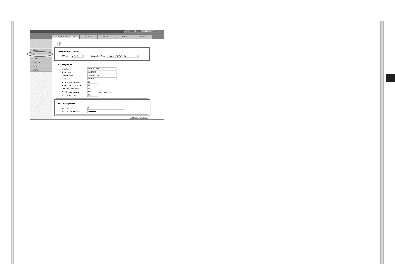
Move the SCC-C6475(P) setup mode to the Basic Configuration ➞ IP page.
■
Assign IP Type as ‘Dynamic IP’ in the Connection Configuration item, if the
user uses SCC-C6475(P) by connecting the ADSL modem, assign
Connection type as ‘ADSL Modem’. If the user uses SCC-C6475(P) by
connecting the Cable modem, assign the Connection type as ‘Cable
Modem’.
●
Be aware if the Connection Configuration item is not set properly to
the user’s network environment, the access cannot be done or the
image cannot be appeared smoothly.
■
If the user uses SCC-C6475(P) by connecting ADSL Modem, enter the
ADSL access ID and Password that ISP has provided in the ADSL
Configuration item.
■
If the user click the Apply button, the message to terminate the internet
browser and reboot the camera will be appeared.
■
After powering off the SCC-C6475(P), separate the PC and the
camera connected to Cross Ethernet cable, and connect the camera to
the network line of ADSL or Cable.
■
And then powering on, the camera will operate as ADSL/Cable Modem
mode and receive to operate a new IP from the ADSL/Cable ISP.
●
ADSL / Cable modem can be delayed or failed as the ISP
condition. In case of this, ON/OFF the modem and wait for
about 1 minute after powering off SCC-C6475(P) and then
power on again.
■
This new ADSL/Cable IP is registered in the DDNS server.
■
User can monitor the image to access the camera after entering the
DDNS address (Example: cfffe42.websamsung.net) in the Remote PC
internet browser.
●
Depends on the ISP condition, the ADSL/Cable IP registered in
DDNS can be delayed to access, wait for about 1~2 minutes
and retry to access if the access fails in the beginning.
■
DDNS Address is composed of 6 figures at the end of SCC-C6475(P)
MAC Address, Alphabet 'c', and the combination of domain name
“websamsung.net”.
Example) If the MAC Address of SCC-C6475(P) is 00:00:f0:ff:fe:42,
DDNS Address = c + fffe42 + websamsung.net =
cfffe42.websamsung.net
3-22
E
3-21
■
If the user install to use the camera in the LAN environment such as intranet
in companies, assign the camera IP by using the Local PC IPinstaller
without any specific setting. In case of this, contact the network manager
about IP, Gateway, and Subnet Mask to be used in the camera and set the
valid value.
■
SCC-C6475(P) is set to operate as Static IP in the LAN environment when it
is shipped.
■
User can enter the IP of the camera or DDNS address in the Local PC
internet browser in the Intranet LAN network and access the camera.
■
If you try to access the camera installed in intranet with a Remote PC in the
LAN out of network, the access can be failed if the firewall is installed.
In case of this, please contact the network manager.
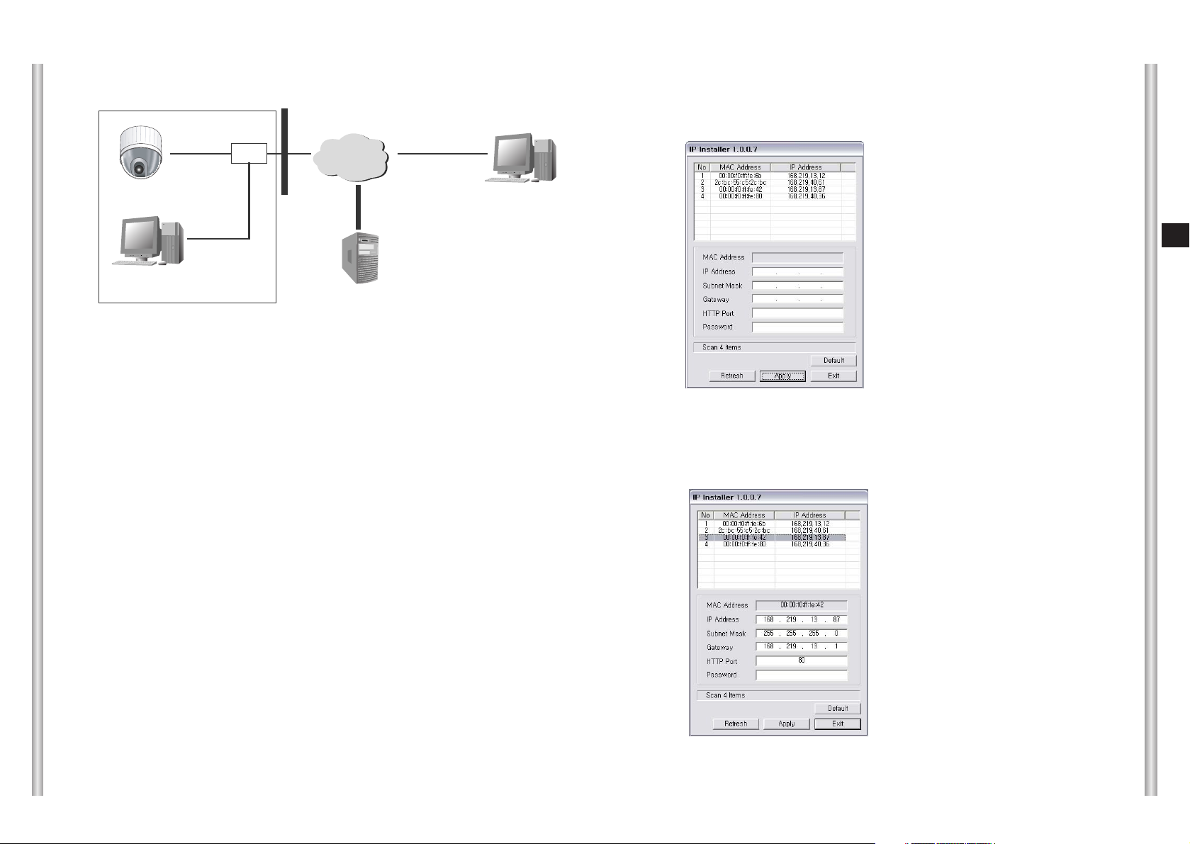
4) In case of connecting the camera in the intranet (LAN)
INTERNET
HUB
SCC-C6475
Local PC
DDNS Server
(Data Center, KOREA)
Remote
2. Setting the IP
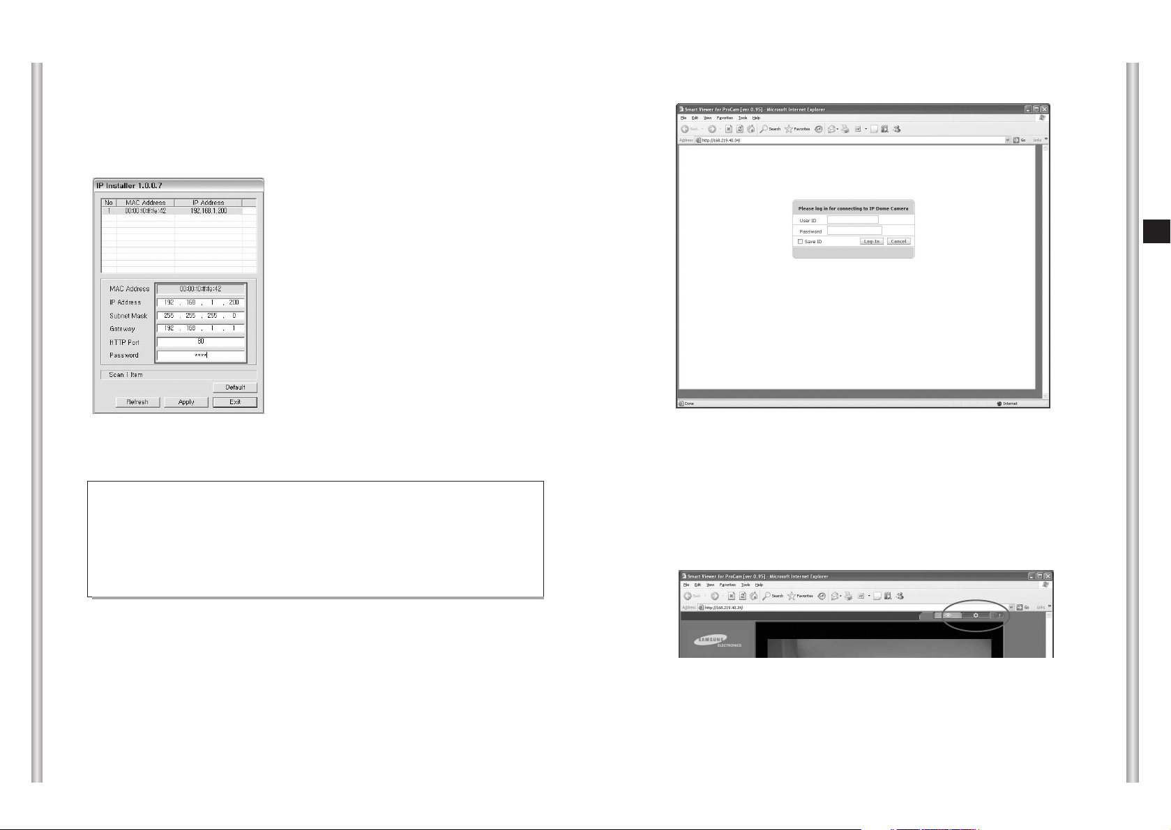
1) If you execute the IPInstaller.exe, find the camera connected the inner
LAN network as follows and show in the display window.
2) Select the desired item and enter the IP and click the Apply button.
Enter as follows and click the Apply button; camera will reboot to set
as the entered IP. The default value of the HTTP Port is 80.
Default password is 4321.
Fire Wall
Double click the item in the search list, and it will be connected with the
relevant camera through the internet browser.
SCC-C6475(P)
3-24
E
3-23
3. Log In.
1) Drive the Internet Explorer and then enter the IP address (Example:
http://192.168.2.75) of the camera or DDNS address (Example:
http://cff0f54.websamsung. net) and move, log in screen as follows
will be displayed.
NNNNoooottttee
ee DDNS Address is composed of 6 figures at the end of SCC-
C6475(P) MAC Address displayed in IPInstaller, Alphabet 'c', and
the combination of domain name “websamsung.net”.
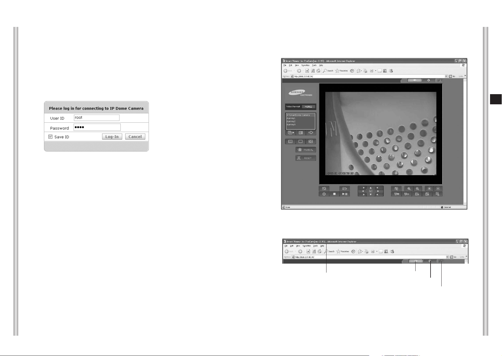
2) Enter the User ID (root) and Password (4321) and log in.
The root ID’s password of the product shipping, be sure to change for
security.
4. Main Screen
Enter the IP address in the Internet Explorer address window and access,
Main display window as follow appears.
Version Info: Displays the version of Viewer ActiveX Control.
Viewer: Moves to the Main screen.
Setup: Moves to the screen that can be set of the camera function.
About: Displays the information, version, manufacturer and etc.
❖
Title bar and the upper menu
Version Info
Viewer
Setup
About
3-26
E
3-25
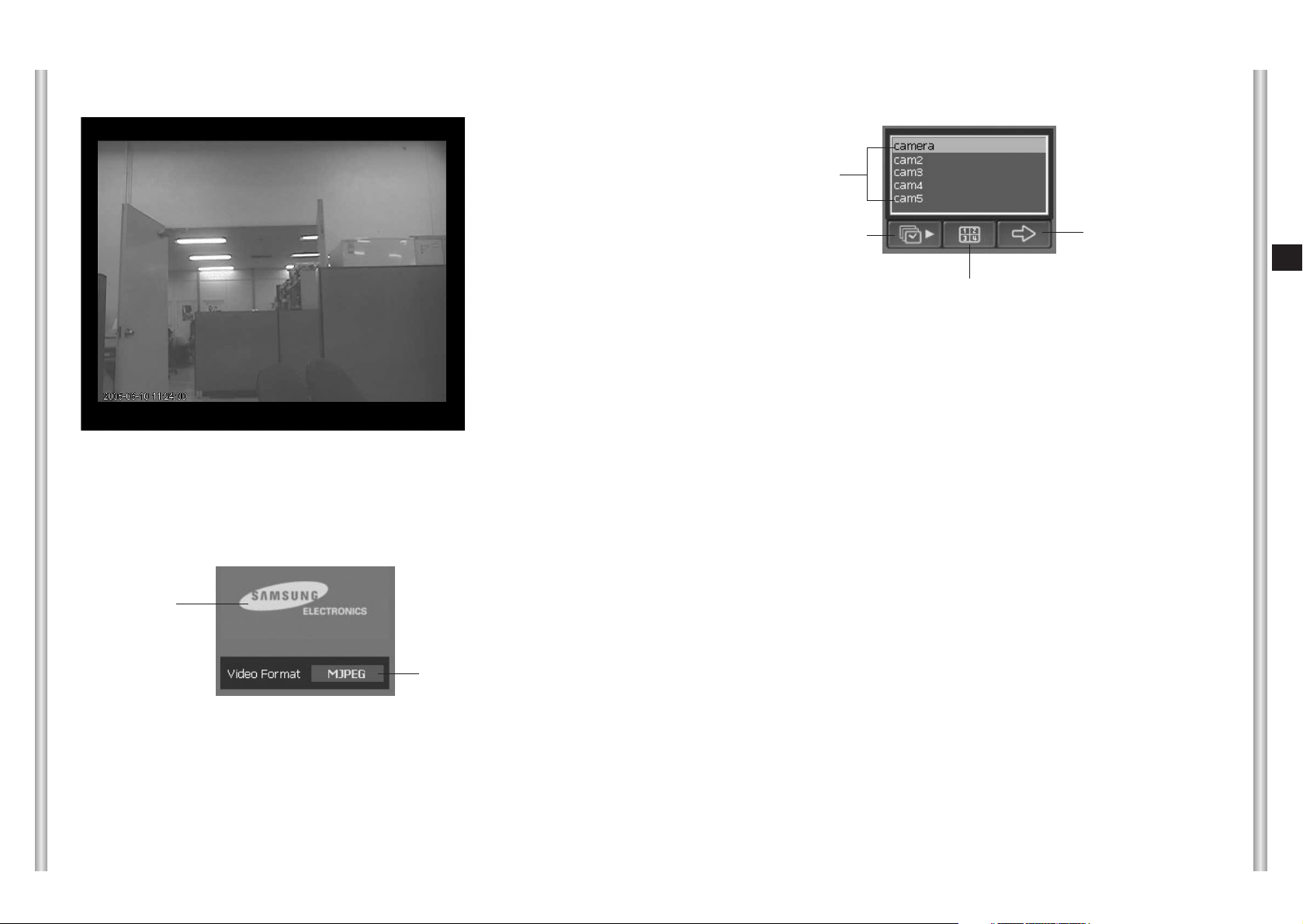
Logo
●
Displays the logo image set at the Setup ➔ Layout ➔ ScreenLook.
●
Samsung electronics logo is set as the initial state.
●
If the logo link is set, clink the logo image and the linked address screen will
be displayed.
Video Format
●
Displays the information of the image format(MJPEG/MPEG4) that is being
shown.
●
Display 704x576(PAL) or 704x480(NTSC), 640x480,
352x288(PAL) or 352x240(NTSC) as resolution.
❖
Viewer Screen
❖
Logo and Video Format
Logo
Video Format
Camera list
●
The top item shows the log in camera, and the below items show the added
camera item in the Setup
➔ Basic Configuration ➔ Camera.
●
The item that has the reversed character is selected by the correspond to the
camera that the image is being shown.
●
If you choose the other camera in the list, the selected camera image will be
displayed.
Sequence Mode
●
Sequence Mode that is set in the Setup ➔ Basic Configuration ➔ Camera will
be executed.
●
If the Sequence Mode is being executed, the other buttons in the main page is
not-activated and can not be used. (Setup, the image screen adjustment
button that has been logged in is usable).
●
Stopping the Sequence Mode, the camera that is being shown at the stop
●
Sequence Mode function can be executed at both 1ch and 4 ch.
1ch/4ch
●
The channel can be changed such as 1ch ➔ 4ch, 4ch ➔ 1ch.
●
In case of 4ch, other buttons in the Main page is non-activated and cannot be
used. (Sequence Mode, Next Camera, Setup, About is available)
●
In case of changing 4ch ➔ 1ch, Log in camera (address window IP camera)will
be selected.
❖
Choice of camera and channel
Camera List
Sequence Mode
1ch/4ch
Next Camera
3-28
E
3-27
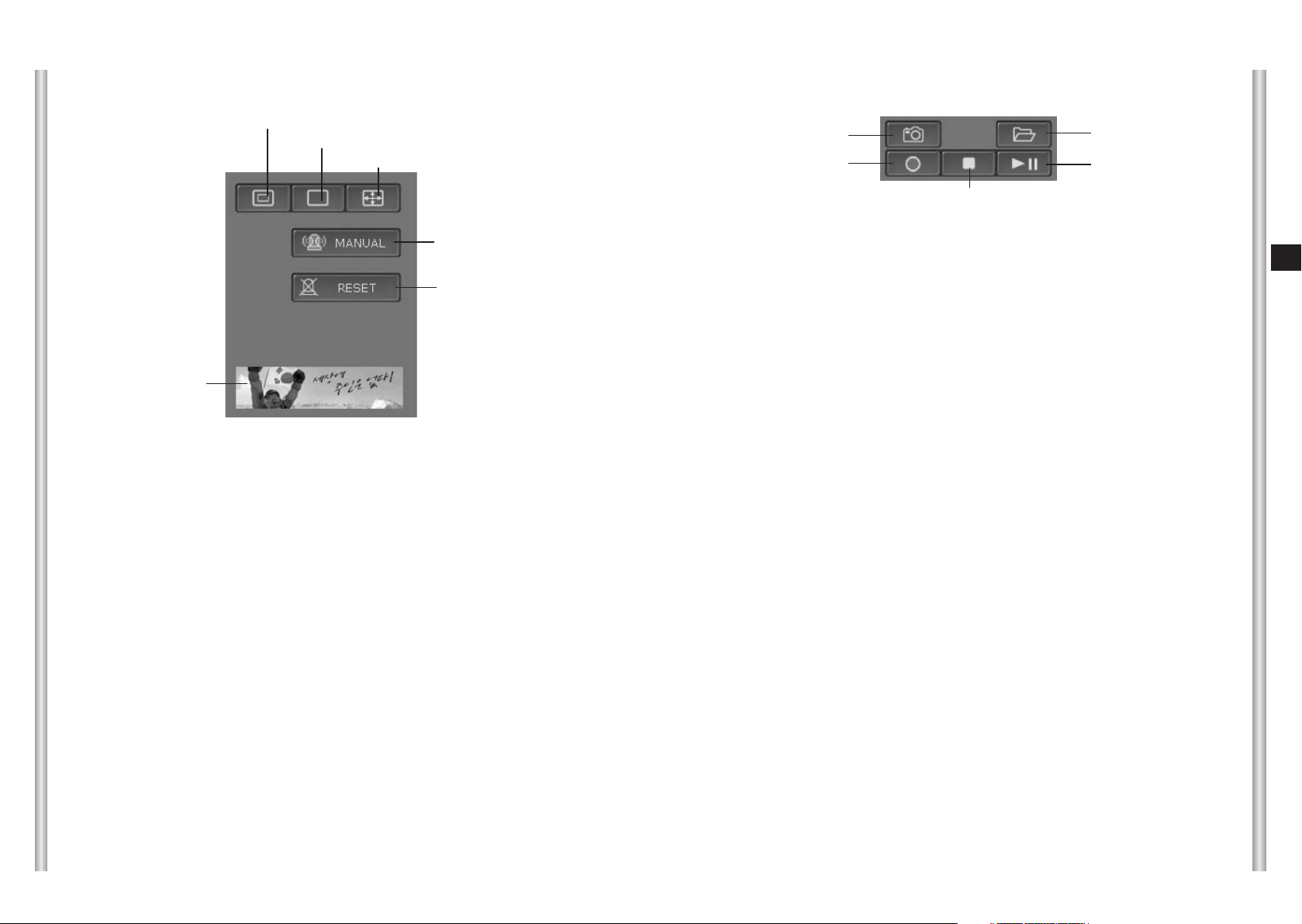
Half size
●
Reduce the image size by half that is being shown.
1:1 size
●
Display the image as the original size that is being shown.
Full Screen
●
Display the image as the full screen that is being shown.
●
Press the ESC key and the Full screen turns to 1:1 size.
MANUAL
●
The button will be activated if the setting (FTP/SMTP send setting, Alarm Setup
setting) about the manual alarm is completed.
●
Press the Manual button, and send the alarm image according to the set matter.
●
Alarm image sending is available only in MJPEG mode.
RESET
●
Cancel the camera location, alarm OUT (buzzer, alarm light) that has been
changed because of alarming.
●
The sending image by the alarming will be canceled automatically after
completing the sending.
Banner display
●
The set banner image will be displayed in the Setup ➔ Layout ➔ ScreenLook.
●
The banner display is not set in the beginning shipment state.
●
If the banner link is set, click the banner image and the linked address screen
will be displayed.
❖
Screen Size/Alarm/Banner window display
Half size
Banner
1:1 size
Full Screen
Manual Alarm
Alarm Reset
Screen Capture
●
Save the image that is being shown with JPEG or BMP format.
- Saving route: C:\Program Files\Samsung\Smart Viewer for ProCam\
Capture(saving route or file format can be changed in Setup
➔ Basic ➔ Video)
- File name: yy/mm/dd_hh/mm/ss_camera name.bmp
(Example: 20050317_144605_IP SmartDome Camera.bmp)
●
Click the button and the saved information will be displayed in the screen.
Record
●
Save the video image to the ‘cam’ format that is being shown.
-
Save route: C:\Program Files\Samsung\Smart Viewer for ProCam\VideoClip
- File name: yy/mm/dd_hh/mm/ss_camera name.cam
●
Click the button and ➔ ‘REC’ will be displayed at the upper right of the screen.
●
Press the “Stop” and the record will be stopped.
●
Only the functions related Alarm and PTZ and Setup, About functions are
available.
❖
Screencapture/record/play
Load
Screen Capture
Record
Stop
Play/Pause
NNNNoooottttee
ee - Can save up to 10 minutes per one time.
- Hard disk operates only when the available capacity is over 5 giga.
Load
●
Press the Load button and call the saved image file and the file name will be
displayed at the left upper side in the screen.
Play/Pause
●
Press Play/Pause button and the image will be played and press this button
while playing, the image will be paused. Press the button again and the image
will be played from the stopped scene.
●
Press Stop button and the image will be stopped and Log in camera image will
be displayed.
●
If the file size is too big, the Load time will take long.
3-30
E
3-29
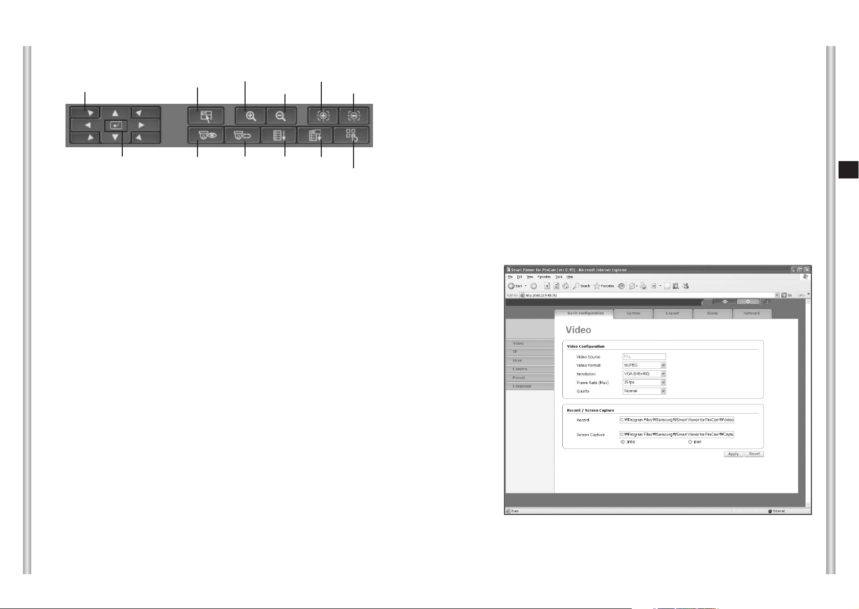
8 direction key
●
It moves the screen position to directions including UP, DOWN, LEFT, and
RIGHT.
●
Press the button to move the screen, remove the button to stop.
Enter
●
Enter function will be operated when Menu on mode.
Menu
●
Press the button, the main screen will be displayed.
Zoom In/Out
●
Press the button and zoom function works, remove the button and zoom
function stops.
Focus Near/Far
●
Focusing while pressing the button and stopped when removing.
●
This function works only in Manual Focus state.
Preset
●
Move the selected Preset item.
●
Click the ‘Refresh’ button in the window that is appeared when pressing the
button, and it will display the latest Preset information set in the camera.
AutoPan
●
Execute the selected AutoPan item.
●
Unable to use Preset, Scan, Pattern, Function while executing.
●
Stop executing if the user click the other control button.
●
Click the ‘Refresh’ button in the window that is appeared when pressing the
button, and it will display the latest Autopan information set in the camera.
Scan
●
Execute the selected Scan item.
●
Unable to use Preset, AutoPan, Pattern, Function while executing.
●
Stop executing if the user click the other control button.
●
Click the ‘Refresh’ button in the window that is appeared when pressing the
button, and it will display the latest Scan information set in the camera.
❖
Image screen adjustment.
8 direction key
Menu
Zoom In
Focus Near
Zoom Out
Focus Far
Preset
AutoPan
Scan
Pattern
Function
Enter
5. Setting and Changing the function
❖
Setting the basic function
Video
Pattern
●
Execute the selected Pattern item.
●
Unable to use Preset, AutoPan, Scan, Function while executing.
●
Stop executing if the user click the other control button.
●
Click the ‘Refresh’ button in the window that is appeared when pressing the
button, and it will display the latest Pattern information set in the camera.
Function
●
Execute the selected Scan item.
●
Unable to use Preset, AutoPan, Scan, Pattern while executing.
3-32
E
3-31
●
Video Source : NTSC / PAL(Display the entered image of Camera.)
●
Video Format : Support MJPEG / MPEG4
●
Resolution
- 4CIF (NTSC: 704x480, PAL: 704x576)
- VGA (640x480)
- CIF (NTSC: 352x240, PAL: 352x288)
●
Frame Rate
- CIF: Support up to 30 frames.
- 4CIF / VGA: Support up to 25 frames.
- Frame phase: 30fps(25fps) / 15fps / 5fps /1fps
●
Quality : Able to select 5 phase (Very High / High / Normal / Low / Very Low)
of picture.
● Record
Enter the route to save.
● Screen Capture
Enter the route to capture the screen. (Select the format to save: JPEG,
BMP)
NNNNoooottttee
ee
- When changing the Resolution, Codec, reboot the encoder so it will
take time to display the image.
- Frame rate is subjected to adjust by the number of access, network
environment; the frame rate can be less than the user set the frame
rate.
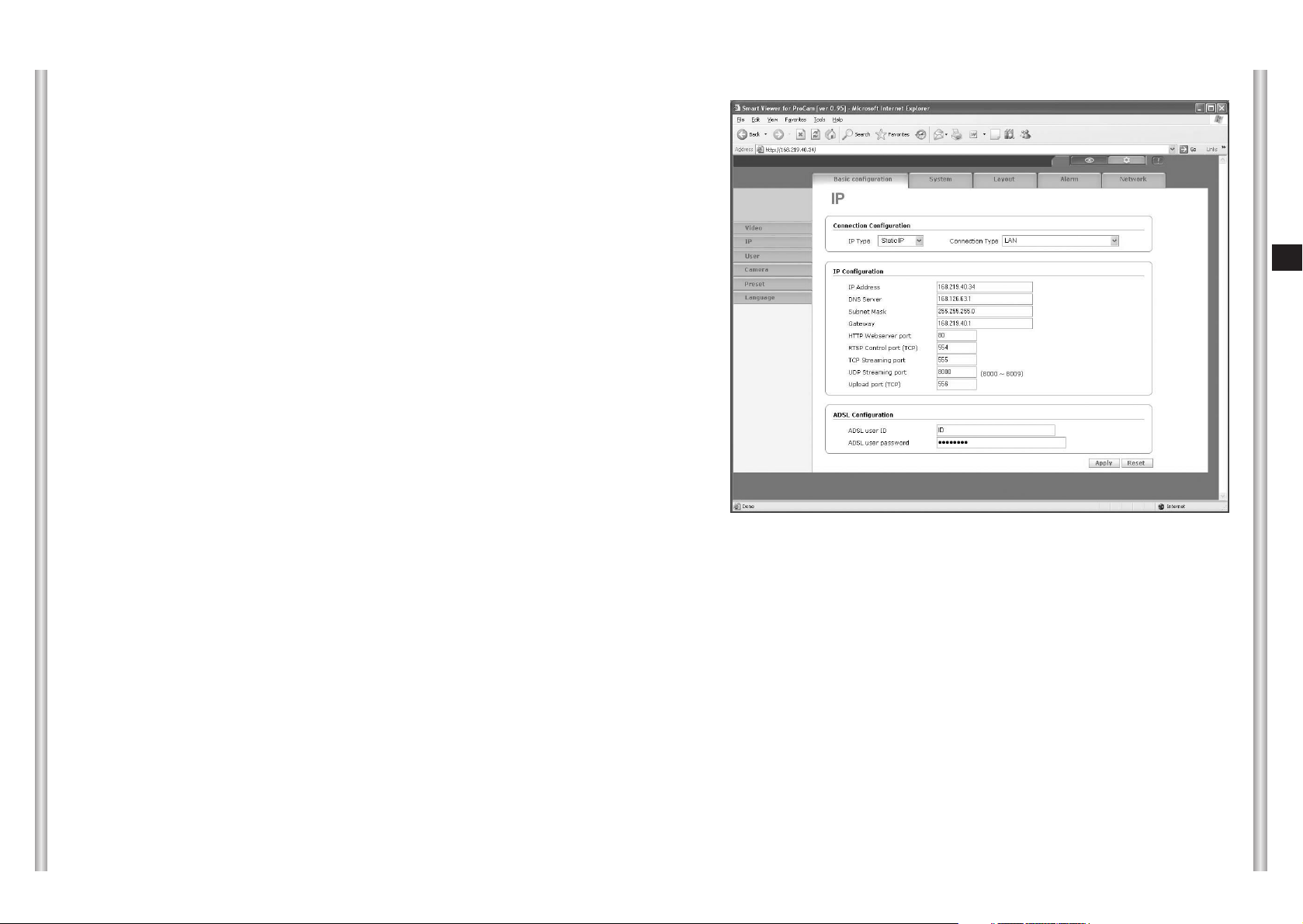
●
Setting the connection
Select the setting value according to the user’s network environment
camera installed.
If the setting is different with the actual installed network environment, the
image cannot display smoothly.
<Select setting according to the network environment>
1. If the camera is installed over the internet using Static IP
- Select IP Type as Static IP.
- If the camera is installed over LAN using static IP, select the connection
type as LAN.
- If the camera is installed directly over the ADSL modem using static IP,
select connection type as ADSL Modem.
- If the camera is connected to the static IP through IP router, select IP
Router + LAN or IP Router +ADSL/Cable.
IP
 Loading...