

SmartDome Camera
User’s Guide
ENG RUS POL
SCC-C6433(P)/C6435(P)
3
Safety Precautions
RISK OF ELECTRIC SHOCK.
CAUTION: TO REDUCE THE RISK OF ELECTRIC SHOCK,
DO NOT REMOVE COVER (OR BACK)
NO USER-SERVICEABLE PARTS INSIDE
REFER SERVICING TO QUALIFIED SERVICE PERSONNEL
CAUTION
DO NOT OPEN
This symbol indicates that dangerous
voltage consisting a risk of electric
shock is present within this unit.
This symbol indicates that there are
important operating and maintenance
instructions in the literature
accompanying this unit.
WARNING
•
To reduce the risk of re or electric shock, do
not expose this appliance to rain or moisture.
•
WARNING
1.
Be sure to use only the standard adapter
that is specied in the specication sheet.
Using any other adapter could cause re,
electrical shock, or damage to the product.
2.
Incorrectly connecting the power supply or
replacing battery may cause explosion, re,
electric shock, or damage to the product.
2
3.
Do not connect multiple cameras to a single
adapter. Exceeding the capacity may cause
abnormal heat generation or re.
4. Securely plug the power cord into the
power receptacle. Insecure connection
may cause re.
5. When installing the camera, fasten it
securely and rmly. A falling camera may
cause personal injury.
6.
Do not place conductive objects (e.g.
screwdrivers, coins, metal things, etc.) or
containers lled with water on top of the
camera. Doing so may cause personal injury
due to re, electric shock, or falling objects.
7. Do not install the unit in humid, dusty, or
sooty locations. Doing so may cause re
or electric shock.
8. If any unusual smells or smoke come
from the unit, stop using the product. In
such case, immediately disconnect the
power source and contact the service
centre. Continued use
in such a condition may cause re or
electric shock.

ENG
3
9. If this product fails to operate normally,
contact the nearest service centre. Never
disassemble or modify this product
in any way. (SAMSUNG is not liable
for problems caused by unauthorized
modications or attempted repair.)
10. When cleaning, do not spray water
directly onto parts of the product. Doing
so may cause re or electric shock.
CAUTION
1. Do not drop objects on the product or
apply strong shock to it. Keep away from
a location subject to excessive vibration
or magnetic interference.
2. Do not install in a location subject to
high temperature (over 122°F), low
temperature (below 14°F), or high
humidity. Doing so may cause re or
electric shock.
3. If you want to relocate the already
installed product, be sure to turn off the
power and then move or reinstall it.
4. Remove the power plug from the outlet
when then there is a lightning.
Neglecting to do so may cause re or
damage to the product.
5. Keep out of direct sunlight and heat
radiation sources. It may cause re.
6. Install it in a place with good ventilation.
7. Avoid aiming the camera directly towards
extremely bright objects such as sun,
as this may damage the CCD image
sensor.
8. Apparatus shall not be exposed to
dripping or splashing and no objects
lled with liquids, such as vases, shall be
placed on the apparatus.
9.
The Mains plug is used as a disconnect device
and shall stay readily operable at any time.

5
Important Safety Instructions
1. Read these instructions.
2. Keep these instructions.
3. Heed all warnings.
4. Follow all instructions.
5. Do not use this apparatus near water.
6. Clean only with dry cloth.
7. Do not block any ventilation openings.
Install in accordance with the
manufacturer’s instructions.
8. Do not install near any heat sources
such as radiators, heat registers, or
other apparatus (including ampliers)
that produce heat.
9. Do not defeat the safety purpose of
the polarized or grounding-type plug.
A polarized plug has two blades with
one wider than the other. A grounding
type plug has two blades and a third
grounding prong. The wide blade or the
third prong is provided for your safety.
If the provided plug does not t into
your outlet, consult an electrician for
replacement of the obsolete outlet.
10. Protect the power cord from being
walked on or pinched particularly at
plugs, convenience receptacles, and the
point where they exit from the apparatus.
11. Only use attachments/accessories
specied by the manufacturer.
12. Use only with cart, stand, tripod, bracket,
or table specied by the manufacturer, or
sold with the apparatus.
4
13. Unplug this apparatus. When a cart is
used, use caution when moving the
cart/apparatus combination to avoid
injury from tip-over.
14. Refer all servicing to qualied service
personnel. Servicing is required when
the apparatus has been damaged in any
way, such as power-supply cord or plug
is damaged, liquid has been spilled or
objects have fallen into the apparatus,
the apparatus has been exposed to rain
or moisture, does not operate normally,
or been dropped.

ENG
5
Contents
Overview ...........................................................................................
About this guide ............................................................................8
Product overview ...........................................................................8
Main features .................................................................................8
Components ...................................................................................8
CHECKING COMPONENTS IN THE PACKAGE .......................8
NAMES OF EACH PART ...........................................................9
Installation .....................................................................................
Before installation .......................................................................10
THINGS TO KEEP IN MIND DURING INSTALLATION AND USE
Initial settings ..............................................................................10
CAMERA ADDRESS SETUP ...................................................10
SETTING COMMUNICATION PROTOCOL ............................. 11
BAUD RATE SETTING ............................................................ 12
SETTING RS-422A/RS-485 TERMINATION ........................... 13
Adapter cable connection ........................................................... 15
Cable connection ......................................................................... 16
Installation precautions ..............................................................19
Separately sold products for installation ..................................19
Installing the camera ...................................................................24
Camera Setup ................................................................................
Camera set ...................................................................................32
CAMERA ID .............................................................................32
V-SYNC .................................................................................... 32
DAY/NIGHT .............................................................................. 33
MOTION DET ........................................................................... 36
ZOOM SPEED .........................................................................39
8
10
.....10
28

7
DIGITAL ZOOM ........................................................................39
DISPLAY ZOOM .......................................................................40
DISPLAY P/T ............................................................................41
EXIT .........................................................................................41
Video set ......................................................................................42
IRIS ..........................................................................................42
ALC ..........................................................................................42
SHUTTER ................................................................................45
AGC..........................................................................................46
MOTION ................................................................................... 47
WHITE BAL .............................................................................. 48
FOCUS MODE ......................................................................... 49
SPECIAL ..................................................................................50
EXIT .........................................................................................52
Preset ...........................................................................................53
Zone set ........................................................................................55
PRIVACY ZONE ....................................................................... 55
ZONE DIR SET ........................................................................56
ZONE AREA SET .....................................................................57
Auto set ........................................................................................60
AUTO PAN ............................................................................... 60
PATTERN .................................................................................62
SCAN .......................................................................................63
AUTO PLAY..............................................................................64
Alarm set ......................................................................................65
ALARM PRIORITY SET ........................................................... 66
ALARM IN SET ........................................................................66
ALARM OUT SET ....................................................................66
6

ENG
7
AUTO SET ...............................................................................66
AUX OUT CONTROL ...............................................................66
Other set ......................................................................................67
PROPORTIONAL P/T ..............................................................67
TURBO P/T ..............................................................................67
AUTO CAL ...............................................................................67
D-FLIP ...................................................................................... 68
CAM RESET ............................................................................68
LANGUAGE .............................................................................68
PASSWORD .............................................................................69
RS-485 .....................................................................................70
Clock set ......................................................................................70
System info ..................................................................................71
Shortcut keys ...............................................................................72
Product Specications ...............................................................
75
9
Overview
About this guide
❚
This user guide includes basic instructions for
the product. It is recommended that all users
read this guide before use.
This guide is divided as follows:
“Overview” introduces the user guide and product
related information.
“Installation” explains how to set and install the
product.
“Camera Setup” presents the structure of the
Setup menu for the SCC-C6435(P)/6433(P)
including a detailed explanation of the functions
performed in each submenu.
“Product Speci cations” provides the
specications of the product.
Product overview
❚
This camera is a zoom lens built in smart
dome camera which provides you with the
best monitoring function in connection with
CCTV at banks or companies. This camera is
a high quality surveillance camera using x32
zoom lens and digital zoom IC, it can catch
clear images up to 510 times.
This camera uses an Alarm function for alert
situations and moving camera in the direction
you want, ZOOM-IN and ZOOM-OUT
functions can be remote controlled.
Note
SCC-C6433(P) does not support for WDR function.
Main features
❚
Power: DC 12V/AC 24V
8
Special functions
WDR to cover the full screen irregardless of its
brightness
DAY/NIGHT to improve the sensitivity by
automatic conversion into the black and white
mode at night or in the environment with low
illumination
White Balance to control the brightness to the
illumination
Backlight Compensation under spotlight or
utmost bright illumination
Auto Focus to automatically adjust the focus
to the subject movement
Privacy zone to hide a specic area for
personal privacy
PAN/TILT for precise control at high speed
Components
❚
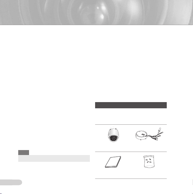
CHECKING COMPONENTS IN THE PACKAGE
Please check your camera and accessories
are included in the package. Those
components are as shown below:
SCC-C6435(P)/C6433(P) Camera Holder Adapter
User’s Guide Screws

ENG
9
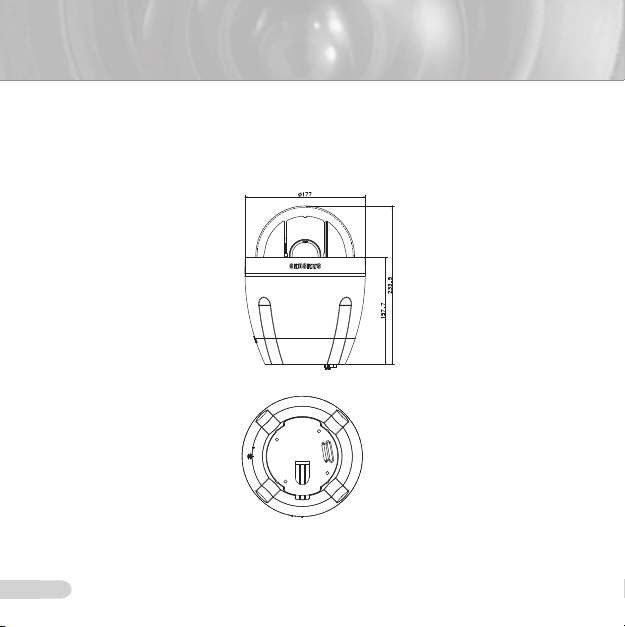
NAMES OF EACH PART
Your camera has the following components:
1. Camera Holder Adapter
2. Camera Body
3. Zoom Lens
4. Cover-dome
5. Alarm Output: N/O, COM, N/C, AO-2, AO-1, GND
6. Alarm Input (1~8): AI-8, AI-7, AI-6, AI-5,GND, AI-4, AI-3, AI-2, AI-1, GND
: TXD+, TXD-, RXD+, RXD-
7. RS-485
8. Power Input: 24V, EARTH, 24V
9. Video Output
11
Installation
Before installation
❚
THINGS TO KEEP IN MIND DURING INSTALLATION AND USE
• Do not disassemble the camera on your own.
• Always be careful when handling the camera. Do not strike the camera by your sts or shake
it. Please be careful not to be careless when storing and operating it.
• Do not place or operate the camera in any wet environment such as rain or wet surfaces.
•
Do not clean the camera with rough sandpaper. Please always use a dry cloth when cleaning it.
•
Put the camera in a cool area free from direct sunlight. Otherwise, the camera may be damaged.
Initial setting
❚
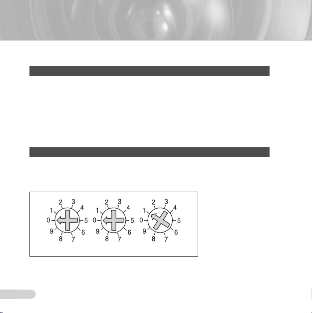
CAMERA ADDRESS SETUP
Use SW703, SW704, or SW705 for Camera Address setup. You may allocate up to 255
addresses by using SW703 to set the 3rd digit, SW704 the 2nd digit, and SW705 the 1st digit.
EX) In case of Camera Address 1, see the following gure for setup.
SW703 SW704 SW705
10

ENG
11
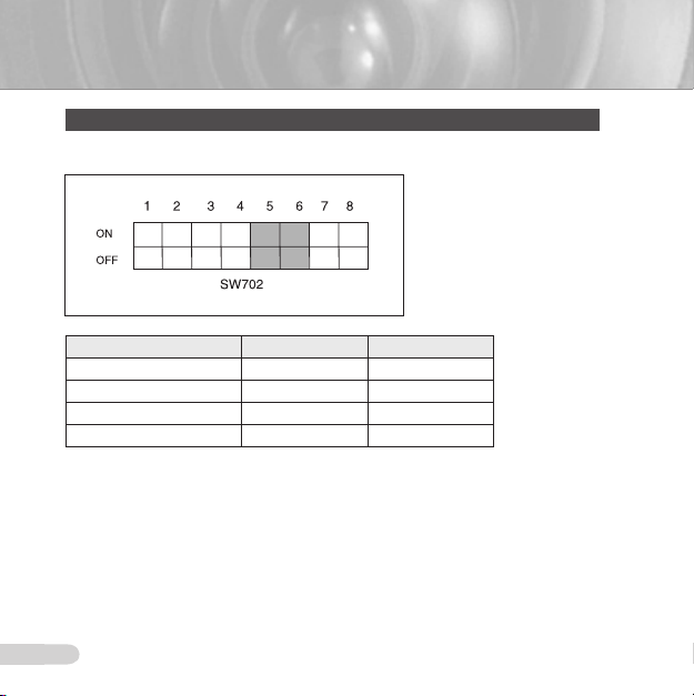
SETTING COMMUNICATION PROTOCOL
X100 X10 X1
Use number 1~4 PIN of SW702 to set communication Protocol.
PIN
Comp
A OFF
B ON
C OFF
D ON
E OFF
F ON
G OFF
H ON
I OFF
J ON
K OFF
L ON
M OFF
N ON
O OFF
P ON
PIN1 PIN2 PIN3 PIN4
OFF OFF OFF
OFF OFF OFF
ON OFF OFF
ON OFF OFF
OFF ON OFF
OFF ON OFF
ON ON OFF
ON ON OFF
OFF OFF ON
OFF OFF ON
ON OFF ON
ON OFF ON
OFF ON ON
OFF ON ON
ON ON ON
ON ON ON
A : SAMSUNG HALF
B : SAMSUNG FULL
<Bottom View of Camera Holder>
13
BAUD RATE SETTING
Use PIN 5 and 6 of SW702.
BAUD RATE PIN 5
4800 BPS ON
9600 BPS OFF
19200 BPS ON
38400 BPS OFF
The factory default setting is set to 9600BPS.
12
PIN 6
ON
ON
OFF
OFF
ENG
13
SETTING RS-422A/RS-485 TERMINATION
As it is shown in the structure map, when Controller and RS-422A/RS-485 is connected,
it should be terminated according to the Cable feature of impedance on the each end of the
transmitting line to transfer the signals in long distance by controlling the reection of the signals
to the lowest.
Division n < 32
Controller
Termination: using numbers 1 and 2 PIN, turn to ON and it will be terminated.
TX+(DATA+)
TX-(DATA-)
CAM 2CAM 1
<RS-485 Half Duplex Organization>
CAM n-1
RX- RX+RX+ RX- RX+ RX- RX+ RX-
CAM n
Termination
SW1-ON

15
Controller
Division
n < 32
Division
SW1-ON
SW2-ON
CAM 1
<RS-422A/RS-485 Full Duplex Organization>
Note
A communication error may occur if you connect multiple cameras that are assigned the same address
in the network.
CAM 2
CAM n-1
CAM n
14

ENG
15
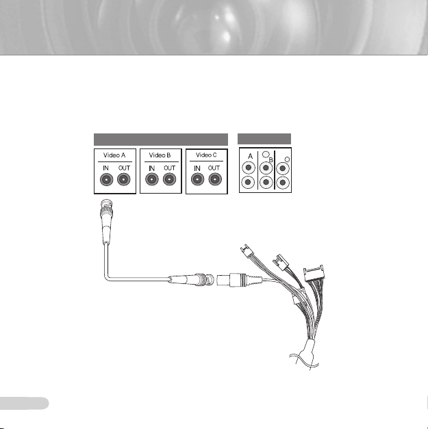
Adapter cable connection
❚
SCC-C6435 Adapter Board
17
Cable connection
IN
OUT
❚
1. First, connect one end of the BNC video cable connector to the Video Output Terminal
(VIDEO OUT).
2. Then, connect the other end of the connector to the Video Input Terminal of the monitor.
Video terminal on the
rear of monitor
BNC Cable
16
ENG
17
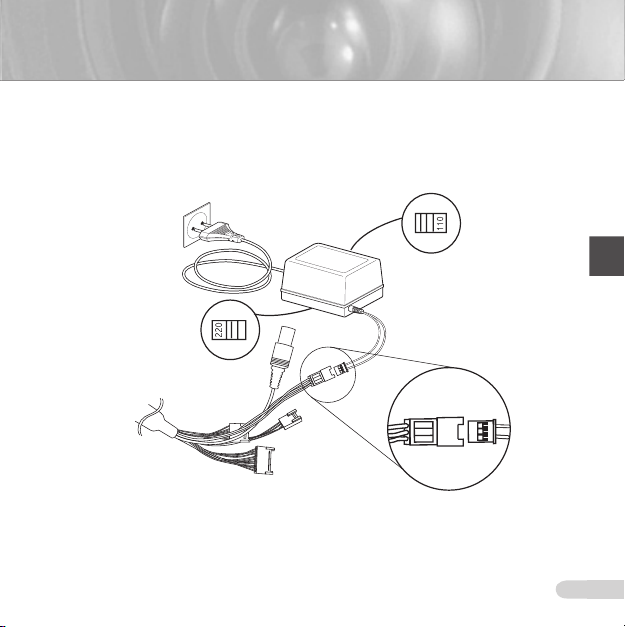
3. Connect the Power Adapter to the Power Cable of the camera.
7
)
5
3
"
&
7
7
&"
3
5)
7
4. Adjust the switch on the Power Adapter to the proper voltage. Then, connect the Power
Adapter's plug to the Power Connector.
Power Selection Switch
under the Power Adaptor
Power Selection Switch
under the Power Adaptor
19
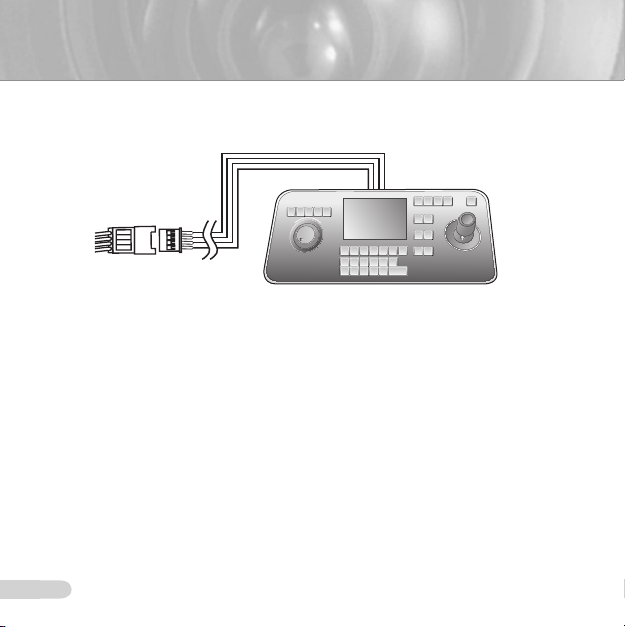
5. Connect the Remote Control Terminal of the camera and the external Controller.
59%
59%
39%
39%
Adapter Cable
Controller
18

ENG
19
Installation precautions
❚
1. Make sure that the installation site can sufciently support a minimum of four times the net
weight of the SCC-C6435(P)/6433(P) SmartDome camera and other accessories.
2. Install in an area where the space above the ceiling board is over 18 cm (7 in.) high.
3. Use the supplied screws to fasten the camera to the bracket assembly.
4. Keep persons away from the installation area, as there is a risk of falling objects.
Also, move valuables to a safe location before installation.
Separately sold products for installation
❚
Depending on the installation site, it may be convenient to use one of the following products.
1. CEILING MOUNT BRACKET (
This bracket is used for installing the SmartDome camera in the plenum above the drop
ceiling.
SADT-101EC)
21
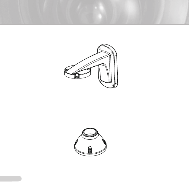
2. WALL MOUNT ADAPTOR (SADT-104WM)
This adaptor is used for installing the SmartDome camera on an indoor wall.
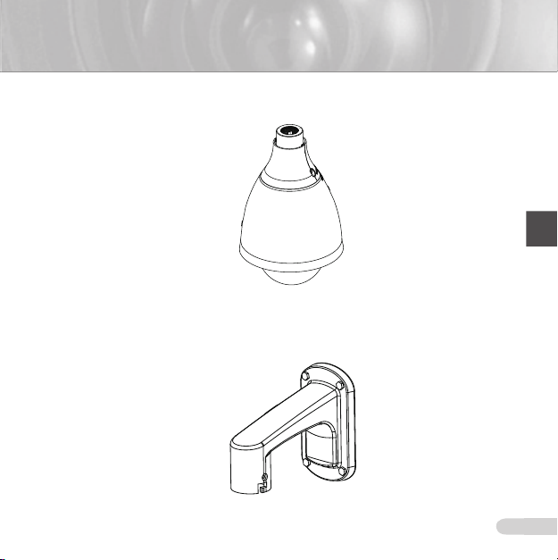
3. HANGING MOUNT ADAPTOR (
This adaptor is used for installing the SmartDome camera to an outdoor wall or a ceiling and
used with CEILING MOUNT ADAPTOR(SADT-100CM).
SADT-100HM)
20
ENG
21
4. OUTDOOR HOUSING (SHG-222)
This housing is used for installing the SmartDome camera to an outdoor wall or a ceiling.
※
To install and use OUTDOOR HOUSING, remove the Clear
before installation.
※
When installing the OUTDOOR HOUSING to an outdoor wall, use WALL MOUNT
ADAPTOR (SADT-103WM) to install it.
Dome from the Camera body

23
5. CEILING MOUNT ADAPTOR (SADT-100CM)
This adaptor is used for installing the OUTDOOR HOUSING(SHG-222) and HANGING
MOUNT ADAPTOR(SADT-100HM) for the SmartDome camera to a concrete ceiling. It is
also used for installing the SmartDome camera with HANGING MOUNT ADAPTOR
(SADT-100HM) to an indoor wall.
6. POLE MOUNT ADAPTOR (SADT-100PM)
This adaptor is used for installing the WALL MOUNT ADAPTOR (SADT-104WM/103WM) to
a pole that is over 8 cm (2.76 in.) in diameter.
22
ENG
23
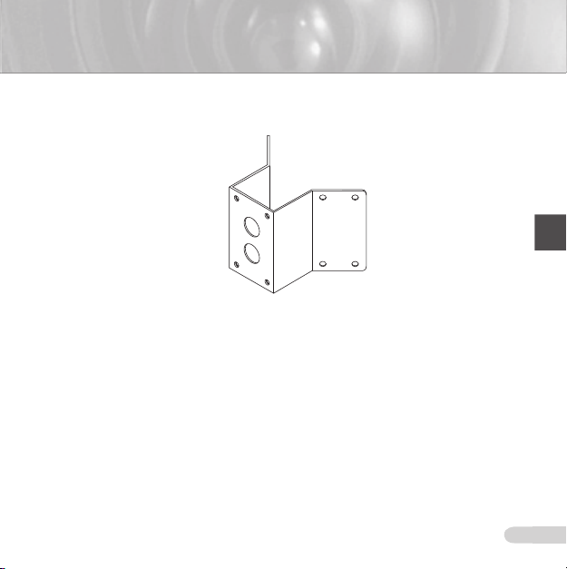
7. CORNER MOUNT ADAPTOR (SADT-110CM)
This adaptor is used for installing the WALL MOUNT ADAPTOR (SADT-104WM/103WM) to
the edge of wall.
25
Installing the camera
❚
1. Install the structure on the ceiling. (Refer to Installation reference for the Length of the
structure)
* Built in by the builder of the structure
2.
Make a hole in the ceiling where the camera will be installed. (The hole should be about ø185)
24
ENG
25
3. Assemble the BRACKET-CEILING on the ceiling and screw the 4 bolts in.
7
)
5
3
"
&
7
7
&"
3
5)
7
IN
OUT
BRACKET-CEILING
4. Connect the various cables to the CAMERA ADAPTER.
Video terminal on the
rear of monitor
BNC Cable
Power Selection
Switch under
the Power Adaptor
Power Selection
Switch under
the Power Adaptor
27
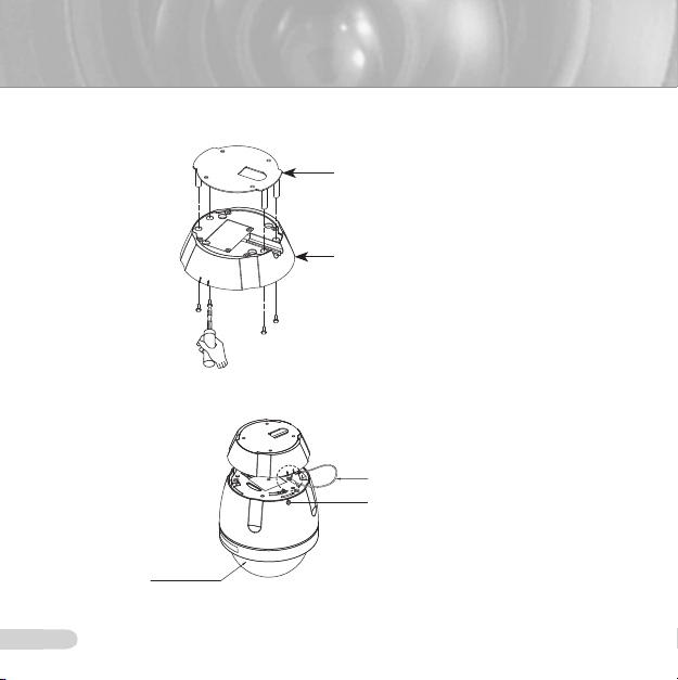
5. Match the BRACKET-CEILING and CAMERA ADAPTER and use 4screws (PH M4 x 8) to
assemble them.
BRACKET-CELING
ASSY-HOLDER CAMERA
6. Pull the safety wire from the case body, and assembly it to the camera holder.
SAFETY WIRE
SCREW(TH M3XL13.8)
DOME
26
ENG
27
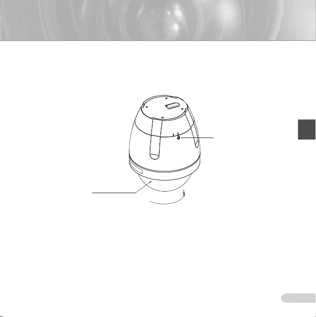
7. Match the 3 holes on the back of the CAMERA and the CONNECTOR and turn it right about
10 degrees. (Check the sound of LOCKING)
* Use the screws (TH M3XL13.8) to connect the CAMERA and the ADAPTER so they don't
move.
SCREW(TH M3XL13.8)
DOME
10°

29
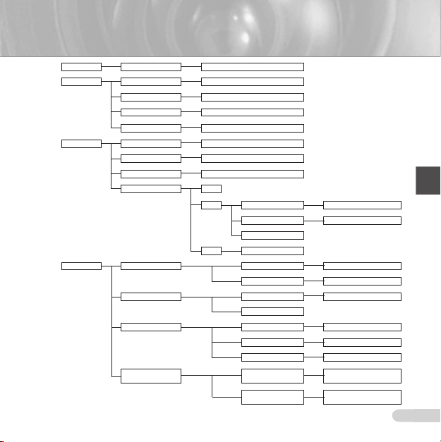
Camera Setup
CAMERA SET ...
VIDEO SET...
Note
*SCC-C6433(P) does not support for WDR function.
28
CAMERA ID OFF/ON...
V-SYNC INT/LINE..
DAY/NIGHT DAY.../NIGHT.../AUTO...
MOTION DET OFF/ON...
ZOOM SPEED 1/2/3/4
DIGITAL ZOOM OFF/X2~X16
DISPLAY ZOOM OFF/ON
DISPLAY P/T OFF/ON
EXIT QUIT/SAVE/PRESET
IRIS ALC.../MANU.../WDR...*
SHUTTER
AGC OFF/LOW/HIGH
MOTION
WHITE BAL ATW1/ATW2/AWC/MANU
FOCUS MODE ONEAF/AF/MF
SPECIAL DNR OFF/ON
EXIT QUIT/SAVE/PRESET
OFF/AUTO X2 ~ AUTO
X256/1/100 ~ 1/10K
S.SLOW/SLOW/NORM/FAST/
F.FAST
FLICKERLESS OFF/ON
REVERSE OFF/H/V/H/V
DETAIL
Y-LEVEL
C-LEVEL
POSI/NEGA
RET
ENG
29
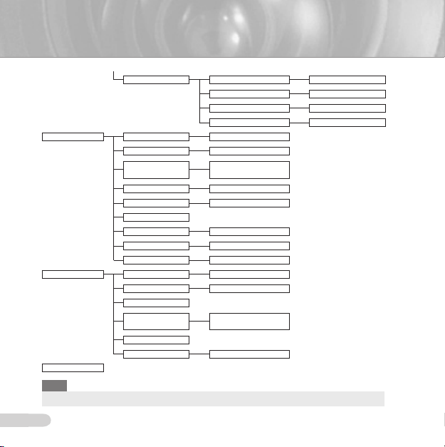
PRESET
ZONE SET...
AUTO SET...
ALARM SET...
PRESET MAP 0~127
PRIVACY ZONE OFF/ON...
ZONE DIR SET OFF/ON...
ZONE AREA SET OFF/ON...
EXIT QUIT/SAVE
AUTO PAN 1/2/3/4
PATTERN 1/2/3
SCAN 1/2/3/4
AUTO PLAY OFF
1... AUTO RETURN OFF/1MIN~12HOUR
AUTO PLAY
PLAY NUMBER 1/2/3/4
2... SET TIME
ALARM PRIORITY SET...
ALARM IN SET... ALARM1~8 NO/NC/OFF
ALARM OUT SET... ALARM1~8 1~3
AUTO SET... ALARM1~8
ALARM1~8 1~8
EXIT QUIT/SAVE
EXIT
MOTION 1~3
EXIT QUIT/SAVE
MOTION
PRESET/SCAN/AUTO PAN/PATTERN
OFF/PATTERN1~3/
HALF1~2/FULL/SCAN1~4
OFF/PATTERN1~3/
HALF1~2/FULL/SCAN1~4
31
AUX OUT CONTROL... OUT1 OFF/ON
OTHER SET...
CLOCK SET...
SYSTEM INFO...
PROPORTIONAL P/T OFF/ON
TURBO P/T OFF/ON
AUTO CAL.
D-FLIP OFF/ON
CAM RESET ...
LANGUAGE*
PASSWORD
RS-485
EXIT QUIT/SAVE
DISPLAY OFF/ON
TIME FORMAT 12HOUR/24HOUR
SET TIME
DATE FORMAT
SET DATE
EXIT QUIT/SAVE
Note
*Selectable languages may vary depending on sales region.
30
OUT2 OFF/ON
OUT3 OFF/ON
EXIT QUIT/SAVE
OFF/6HOUR/12HOUR/
18HOUR/24HOUR
OFF/ON
...
MM/DD/YYYY DD/MM/YYYY
YYYY/MM/DD
 Loading...