


SCC-C6415P
Smart Dome Camera
User Manual
imagine the possibilities
Thanks you for purchasing this Samsung product.
To receive a more complete service, please visit
our website
www.samsungsecurity.com
overview
CAUTION
RISK OF ELECTRIC SHOCK.
DO NOT OPEN
CAUTION: TO REDUCE THE RISK OF ELECTRIC SHOCK, DO NOT REMOVE COVER (OR BACK) NO USER
SERVICEABLE PARTS INSIDE. REFER SERVICING TO QUALIFIED SERVICE PERSONNEL.
This symbol indicates that dangerous voltage consisting a risk of
electric shock is present within this unit.
This symbol indicates that there are important operating and
maintenance instructions in the literature accompanying this unit.
WARNING
y
To reduce the risk of fi re or electric shock, do not expose this appliance to rain or
moisture.
y
To prevent injury, this apparatus must be securely attached to the fl oor/wall in
accordance with the installation instructions.
WARNING
Be sure to use only the standard adapter that is specifi ed in the specifi cation sheet.
1.
Using any other adapter could cause fi re, electrical shock, or damage to the
product.
Incorrectly connecting the power supply or replacing battery may cause explosion,
2.
fi re, electric shock, or damage to the product.
Do not connect multiple cameras to a single adapter. Exceeding the capacity may
3.
cause abnormal heat generation or fi re.
Securely plug the power cord into the power receptacle. Insecure connection may
4.
cause fi re.
When installing the camera, fasten it securely and fi rmly. The fall of camera may
5.
cause personal injury.
Do not place conductive objects (e.g. screwdrivers, coins, metal parts, etc.) or
6.
containers fi lled with water on top of the camera. Doing so may cause personal
injury due to fi re, electric shock, or falling objects.
Do not install the unit in humid, dusty, or sooty locations. Doing so may cause fi re
7.
or electric shock.
2_ overview

If any unusual smells or smoke come from the unit, stop using the product. In such
8.
case, immediately disconnect the power source and contact the service center.
Continued use in such a condition may cause fi re or electric shock.
If this product fails to operate normally, contact the nearest service center. Never
9.
disassemble or modify this product in any way. (SAMSUNG is not liable for
problems caused by unauthorized modifi cations or attempted repair.)
10.
When cleaning, do not spray water directly onto parts of the product. Doing so may
cause fi re or electric shock
11.
Do not expose the product to the direct airfl ow from an air conditioner.
Otherwise, it may cause moisture condensation inside the Clear Dome due to
temperature difference between internal and external of the dome camera.
12.
If you install this product in a low-temp area such as inside a cold store, you must
seal up the wiring pipe with silicon, so that the external air can not fl ow inside the
housing. Otherwise, external high, humid air may fl ow inside the housing, pooling
moisture or vapor inside the product due to a difference between internal and
external temperature.
CAUTION
1.
Do not drop objects on the product or apply strong blows to it. Keep away from a
location subject to excessive vibration or magnetic interference.
2.
Do not install in a location subject to high temperature (over 50°C), low temperature
(below -10°C), or high humidity. Doing so may cause fi re or electric shock.
3.
If you want to relocate the already installed product, be sure to turn off the power
and then move or reinstall it.
4.
Remove the power plug from the outlet when there is a lighting storm. Neglecting
to do so may cause fi re or damage to the product.
5.
Keep out of direct sunlight and heat radiation sources. It may cause fi re.
6.
Install it in a place with good ventilation.
7.
Avoid aiming the camera directly towards extremely bright objects such as sun, as
this may damage the CCD image sensor.
8.
Apparatus shall not be exposed to dripping or splashing and no objects fi lled with
liquids, such as vases, shall be placed on the apparatus.
9.
The Mains plug is used as a disconnect device and shall stay readily operable at
any time.
10.
When using the camera outdoors, moisture may occur inside the camera due
to temperature difference between indoors and outdoors. For this reason, it is
recommended to install the camera indoors. For outdoor use, use the camera with
built-in fan and heater.
English
English _3
overview
IMPORTANT SAFETY INSTRUCTIONS
Read these instructions.
1.
Keep these instructions.
2.
Heed all warnings.
3.
Follow all instructions.
4.
Do not use this apparatus near water.
5.
Clean only with dry cloth.
6.
Do not block any ventilation openings. Install in accordance with the manufacturer’s
7.
instructions.
Do not install near any heat sources such as radiators, heat registers, or other
8.
apparatus (including amplifi ers) that produce heat.
Do not defeat the safety purpose of the polarized or grounding-type plug.
9.
A polarized plug has two blades with one wider than the other. A grounding type
plug has two blades and a third grounding prong. The wide blade or the third prong
is provided for your safety. If the provided plug does not fi t into your outlet, consult
an electrician for replacement of the obsolete outlet.
Protect the power cord from being walked on or pinched particularly at plugs,
10.
convenience receptacles, and the point where they exit from the apparatus.
Only use attachments/accessories specifi ed by the manufacturer.
11.
Use only with the cart, stand, tripod, bracket, or table specifi ed
12.
by the manufacturer, or sold with the apparatus. When a
cart is used, use caution when moving the cart/apparatus
combination to avoid injury from tip-over.
Unplug this apparatus during lightning storms or when unused
13.
for long periods of time.
Refer all servicing to qualifi ed service personnel. Servicing is required when the
14.
apparatus has been damaged in any way, such as powersupply cord or plug is
damaged, liquid has been spilled or objects have fallen into the apparatus, the
apparatus has been exposed to rain or moisture, does not operate normally, or has
been dropped.
4_ overview
Apparatus shall not be exposed to dripping or splashing and no objects
filled with liquids, such as vases, shall be placed on the apparatus

CONTENTS
OVERVIEW
2
INSTALLATION &
CONNECTION
8
SETUP
18
APPENDIX
46
4 Important Safety Instructions
5 Contents
6 Features
6 What’s Included
7 At a Glance
8 Preparing Installation
8 Installation
12 Initial Setup
15 Connecting With Other Device
18 How to use the Keyboard
Controller
19 Main Menu
20 Profi le
22 Camera Set
31 Intelligent Video
32 Privacy Zone
33 Preset
35 Auto Set
39 Zone Set
40 Alarm Set
42 Clock Set
42 Other Set
44 Communication
44 System Info
45 Language
46 Shortcut Keys
47 Specifi cations
49 Product Appearance
English
English _5
overview
FEATURES
y
With the state-of-the-art digital signal processing technology, full digital image
processing and special algorithm of 600-line high resolution implemented
y
High performance surveillance camera, equipped with x25 zoom lens and digital
zoom IC, enabling monitoring up to 400 times
y
WDR to cover the full screen irregardless of its brightness
y
DAY/NIGHT to improve the sensitivity by automatic conversion into the black and
white mode at night or in the environment with low illumination
y
White Balance to control the brightness to the illumination
y
Backlight Compensation under spotlight or utmost bright illumination
y
Auto Focus to automatically adjust the focus to the subject movement
y
Privacy zone to hide a specifi c area for personal privacy
y
PAN/TILT for precise control at high speed
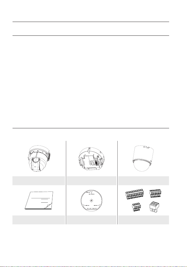
WHAT’S INCLUDED
Please check if your camera and accessories are all included in the product package.
SW602
Camera Frame Set Cover
User Manual
User Manual Template Connectors
6_ overview
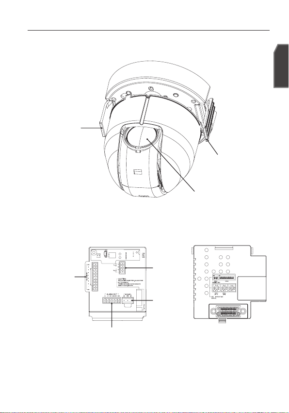
AT A GLANCE
CAMERA
HOOK
FRAME SET
ALARM IN
RS-485
POWER
INPUT
LENS
HOOK
ON
ON
1 2
12345678
English
SW604
(x 1)
ALARM OUT
Wipe out a dirty surface of the lens softly with a lens tissue or cloth to which you
M
have applied ethanol.
English _7
installation & connection
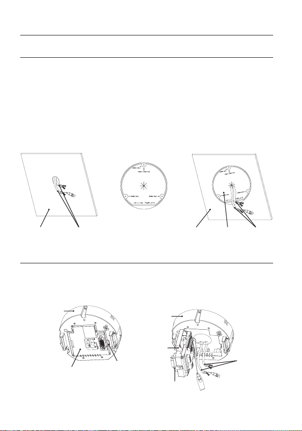
PREPARING INSTALLATION
y
Use the ceiling installation template when you install the camera on the ceiling on
your own.
y
Run the cables through the “” shaped hole on the center of the template, and
remove fi lms on the adhesives, and then attach the template on the desired location
on the ceiling.
y
When installing the frames set, align all template’s screw holes and those of the
frames set.
y
This template prevents dust entering from the ceiling into the camera assembly.
<TEMPLATE>
CABLESCEILING CABLESCEILING TEMPLATE
INSTALLATION
1.
Press the “SNAP FIT” on the “ADAPTOR” to open the “ADAPTOR”, and arrange
cables so they pass out of the “FRAME SET”.
FRAME SET
ADAPTOR
SNAP FIT
8_ installation & connection
FRAME SET
ADAPTOR
EXTERNAL
CABLES
SNAP FIT
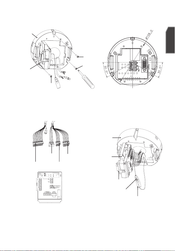
Use the three “SCREWS” to fi x the “FRAME SET” on a “CAMERA” installation
2.
position.
FRAME SET
SCREW
SCREW
ADAPTOR
SCREW
<Fixing Hole Diagram>
Connect external cables to the “CONNECTORS(ALARM IN, POWER, RS-485,
3.
ALARM OUT)”and connect the “CONNECTOR” to the “ADAPTOR”.
Insert the cable into the “FRAME SET”, and close the “ADAPTOR”.
FRAME SET
POWER INPUT
ALARM IN
ALARM OUT
RS-485
ADAPTOR
SNAP FIT
BNC JACK
INSULATION TUBE
English
Then, wrap the “BNC JACK” with the “INSULATION TUBE”, and use an insulation
M
tape to seal up the end of the “INSULATION TUBE” so that the “BNC JACK” does
not protrude outside of the “INSULATION TUBE” coating.
For more information about cable connection, refer to “Connecting the adaptor
cable”. (page 17)
English _9
installation & connection
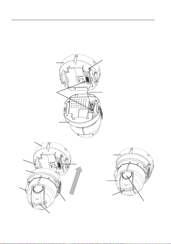
Connect the “SAFETY WIRE” of the “CAMERA” to the “BRACKET WIRE” on the
4.
“FRAME SET”. Arrange the “22P CONNECTOR” of the “CAMERA” in line with that
of the “ADAPTOR”, push the “HOOK” on either end of the “CAMERA” in the “RACK”
direction of the “FRAME SET” to secure the two.
Then, ensure that all of the two “HOOKS” “clicks” to fi x to the “RACK” properly.
FRAME SET
22P CONNECTOR
CAMERA
FRAME SET
RACK
CAMERA
HOOK
HOOK
PROTECTIVE TAPE
When the installation is completed, remove the “PROTECTIVE FILM” and
M
“PROTECTIVE TAPE” from on the lens.
10_ installation & connection
BRACKET WIRE
SAFETY WIRE
FRAME SET
RACK
CAMERA
PROTECTIVE TAPE
PROTECTIVE FILM
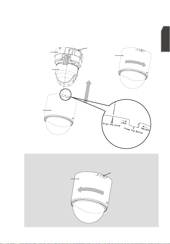
Arrange the “COVER” arrow in line with the “FRAME SET” arrow, and push in the
5.
“COVER”. Insert the “COVER” to the end, and turn the “COVER” clockwise.
As shown in the fi gure below, turn it until you see the “BUTTON” hole and hear a
click.
Ensure that the “COVER” should not move any further if you turn the “COVER” counter
clockwise.
FRAME SET
CAMERA
COVER
If you want to remove the “COVER”, hold down the “BUTTON” and turn the
“COVER” counter clockwise to remove the “COVER”.
COVER
BUTTON
COVER
BUTTON
English
English _11
installation & connection
ON
SW604
(x 1)
ON
1 2
12345678
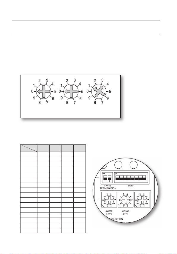
INITIAL SETUP
Camera Address Setup
Use SW606, SW605, and SW604 to specify the camera address.
You can specify between 0 and 255 for the address, where the hundreds digit is
with SW606, the tens digit with SW605, and the ones digit with SW604.
ex) Camera address: If the address is 1, follow the steps in the figure below.
SW606
(x100)
SW605
(x10)
SW604
(x1)
Communication Protocol Setup
Use pins #1~#4 of SW603 to specify the communication protocol.
PIN
Comp
12_ installation & connection
PIN1 PIN2 PIN3 PIN4
A OFF OFF OFF OFF
B ON OFF OFF OFF
C OFF ON OFF OFF
D ON ON OFF OFF
E OFF OFF ON OFF
F ON OFF ON OFF
G OFF ON ON OFF
H ON ON ON OFF
I OFF OFF OFF ON
J ON OFF OFF ON
K OFF ON OFF ON
L ON ON OFF ON
M OFF OFF ON ON
N ON OFF ON ON
O OFF ON ON ON
PONONONON
A : SAMSUNG HALF
B : SAMSUNG FULL
<Bottom of the camera holder>
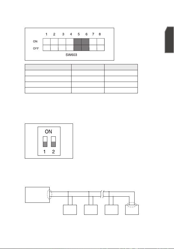
Baud Rate Setup
Use pins #5, #6 of SW603 to set the baud rate.
BAUD RATE PIN 5 PIN 6
4800 BPS ON ON
9600 BPS OFF ON
19200 BPS ON OFF
38400 BPS OFF OFF
The factory default is 9600 BPS.
Setting RS-422A/RS-485 Termination
As it is shown in the structure map, when Controller and RS-422A/RS-485 is
connected, it should be terminated according to the Cable feature of impedance
on the each end of the transmitting line to transfer the signals in long distance by
controlling the reflection of the signals to the lowest.
CAM n-1
n < 32
RX-
CAM n
Termination
SW1-ON
RX+
Termination
Controller
TX+(DATA+)
TX-(DATA-)
RX+ RX- RX+ RX- RX+ RX-
CAM 1
CAM 2
<RS-485 Half Duplex Organization>
Termination : Using numbers 1 and 2 PIN, turn to <ON> and it will be terminated.
English
English _13
installation & connection
Controller
Termination
CAM 2CAM 1
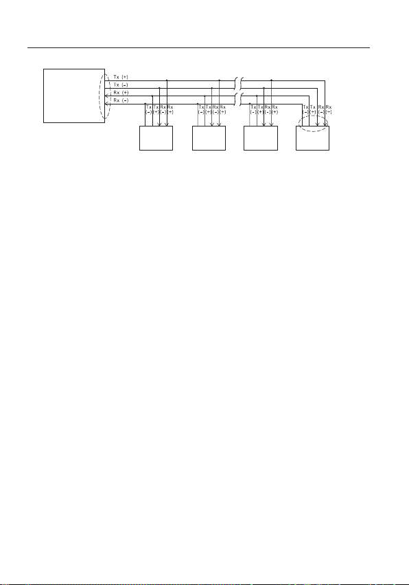
<RS-422A/RS-485 Full Duplex Organization>
A communication error may occur if you connect multiple cameras that are assigned
M
the same address in the network.
CAM n-1
n < 32
CAM n
Termination
SW1-ON
SW2-ON
14_ installation & connection
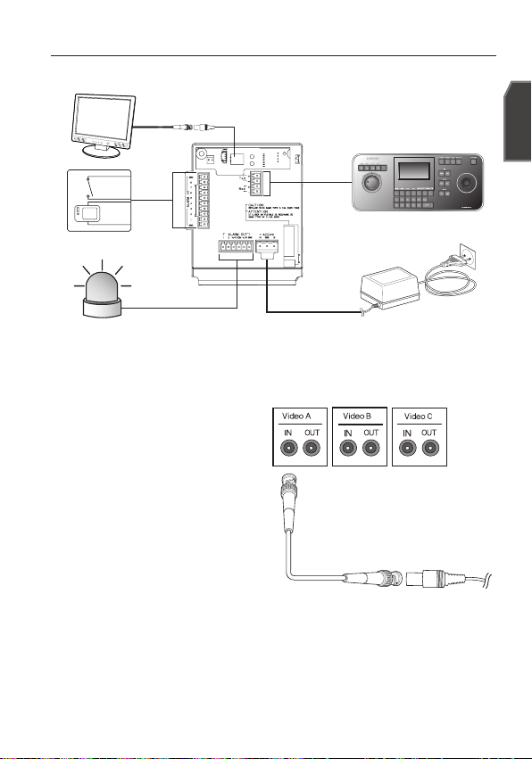
CONNECTING WITH OTHER DEVICE
MONITOR
ALARM IN
ALARM OUT
Connecting to a monitor
Connect one end of the BNC
1.
video cable connector to the
Video Output Terminal (VIDEO
OUT).
2.
Connect the other end of the
connector to the Video Input
Terminal of the monitor.
English
CONTROLLER/DVR
POWER SOURCE
Video terminal on the
rear of monitor
BNC Cable
English _15
installation & connection
To connect ALARM IN
1.
Connect one end of the external device's signal line to a corresponding ALARM
IN port of the monitor.
2.
Connect the other end of the signal line to the earth-grounding [GND] port.
To connect ALARM OUT
Connect one end of the external device's signal line to a corresponding ALARM
1.
OUT port of the monitor.
2.
Connect the other end of the signal line to the common [COM] port.
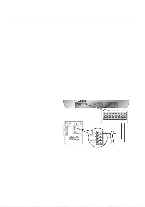
To connect the controller
Connect an external controller or DVR to the camera, with which you can adjust the
camera.
1.
Connect the Rx+ pin of the
camera to the Tx+ pin of the
controller.
2.
Connect the Rx- pin of the
camera to the Tx- pin of the
controller.
3.
Connect the Tx+ pin of the
camera to the Rx+ pin of the
controller.
4.
Connect the Tx- pin of the
camera to the Rx- pin of the
controller.
TxRx
16_ installation & connection

Connecting the adaptor cable
Adaptor Board
English
Power Supply
Connect the cables as necessary, and turn on the camera to check if it works
properly.
1.
Connect the adaptor to the power terminal of the camera.
2.
Plug the power cord of the adaptor into the wall outlet.
English _17

setup
Connect the camera to the keyboard controller or DVR, with which you
can manipulate and change the settings of the camera.
HOW TO USE THE KEYBOARD CONTROLLER
Follow the steps below to set the camera menu using the controller.
1.
Open the Camera Setup screen.
2.
Use the joystick to navigate through the menus.
3.
Press [ENTER] to select a menu item.
4.
Use the joystick to change the value of the selected item.
5.
Press [ENTER] to apply your changes.
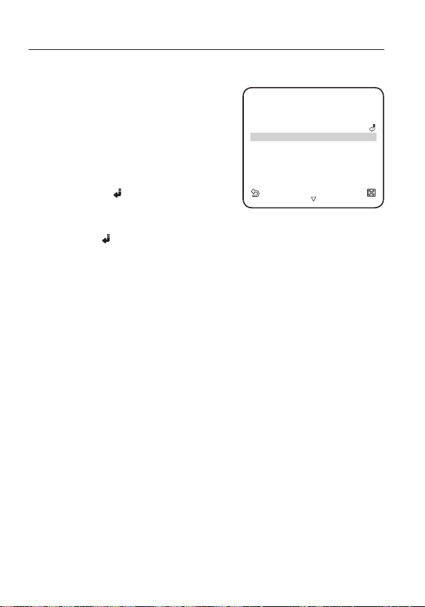
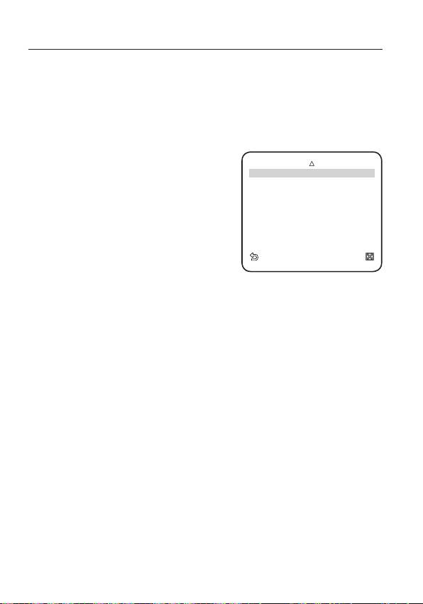
Using OSD icons
y
◄►
:
If these icons appear in the left and right corner of a menu item, you can use
the joystick to move to the previous or next menu.
y
(EXIT): Exits the menu setup screen.
Before exiting the setup screen, select <SAVE> to save your settings
to the whole menus, or <QUIT> to cancel them.
y
(RET): Saves your settings and returns to the previous screen.
y
(HOME): Returns to the main menu.
y
(SAVE): Use this icon if you want to save your settings after you specifi ed the
mask area and privacy area, etc.
Once you saved your settings, the changes remain intact even if you
select <QUIT> on exit.
y
(DEL): Use this icon if you want to delete a mask, or privacy area, etc.
Once you deleted your settings, the deletions remain valid even if you
select <QUIT> on exit.
y
: This icon appears in the right of a menu containing sub menu items.
M
18_ setup
While any operation of PRESET, AUTO PAN, SCAN, and PATTERN is running, and if
the camera is turned off and back on without any particular manipulation, the
camera will resume the last run operation.
You can set the menu item only if the tilt angle is within 90°.
If you enter the menu setup screen with the camera positioned out of a tilt of 90°,
the camera will rotate by 180° to fall into the opposite position within a tilt of 90°.

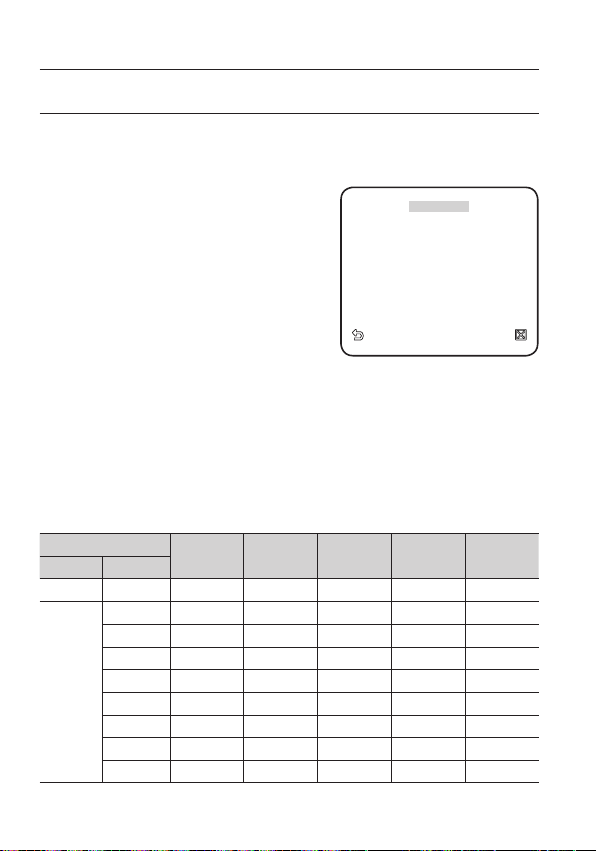
MAIN MENU
¾¾
MAIN M ENU
¾¾
CAMERA SE T
INTELLI GENCE
PRIVACY ZONE
PRESET
AUTO SET
ZONE SE T
ALARM S ET
CLOCK S ET
OTHER S ET
SYSTEM INFO
LANGUAG E
This is the first screen you ever see when you turn on the camera where you can set the
camera environment to your needs.
For selecting and saving each menu item, refer to “How to use the keyboard controller”. (page 18)
y
PROFILE
Select a mode appropriate to the camera
installation environment.
y
CAMERA SET
You can confi gure the camera settings.
y
INTELLIGENCE
Offers motion detection and tracking
functions.
y
PRIVACY ZONE
You can confi gure the privacy settings.
y
PRESET
You can set the PRESET POSITION and
DURATION.
y
AUTO SET
Contains sub menu items of AUTO PAN,
PATTERN, and SCAN.
y
ZONE SET
You can set the standard azimuth and zone
area for the camera.
y
ALARM SET
You can set the alarm priority and I/O sequence.
y
CLOCK SET
You can set the display time and format.
y
OTHER SET
You can reset the camera, or adjust the OSD color to your preference.
y
COMMUNICATION
Confi gures the settings pertaining to RS-485 communication.
y
SYSTEM INFO
Shows the system information such as the camera version or communication
settings.
y
LANGUAGE
Select a preferred one from the supported languages.
¾¾
MAIN MENU
PROFILE
CAMERA SET
INTELLIGENCE
PRIVACY ZONE
PRESET
AUTO SET
ZONE SET
ALARM SET
CLOCK SET
OTHER SET
COMMUNICATION
SYSTEM INFO
LANGUAGE
¾¾
English
English _19
setup
¾
STANDARD
ITS
BACKLIG HT
DAY/NIGHT
GAMING
CUSTOM
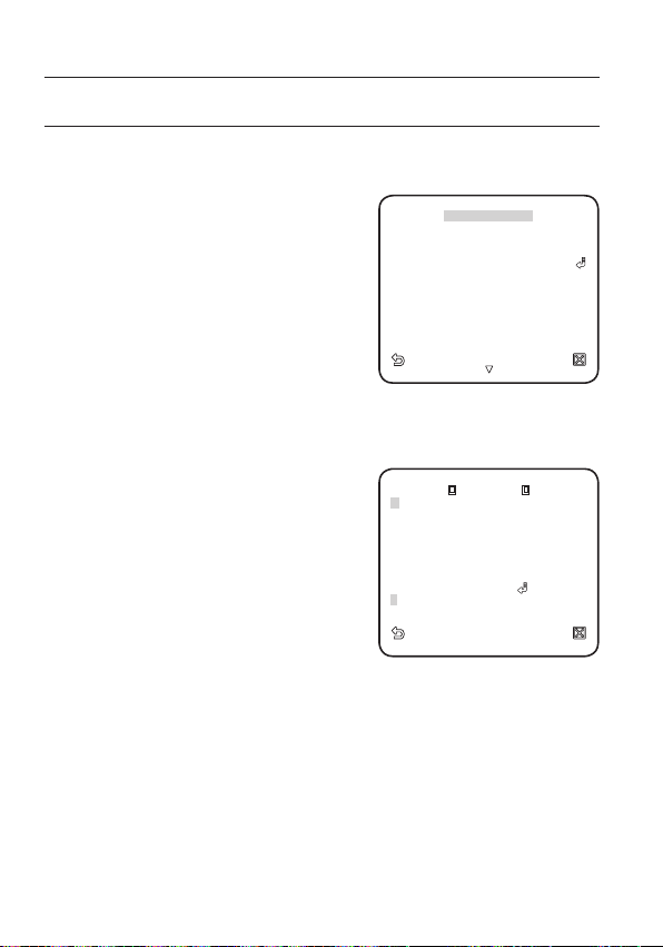
PROFILE
You can select one from the pre-determined configurations as appropriate to your
specific camera installation environment.
Your selection on each item in PROFILE will affect all other settings of the camera.
y
STANDARD
Automatically optimizes the camera settings
to the normal environment.
y
ITS
This setting enables you to analyze the traffi c
situation and take the traffi c information at a
glance.
y
BACKLIGHT
This setting enables you to view a sharp
background and object even in a severe
backlight scene.
y
DAY/NIGHT
Automatically optimizes the camera settings to the day and night scene.
y
GAMING
This automatically configures the settings so that you can work in a stable illumination condition as indoors.
y
CUSTOM
Your change to any of the PROFILE settings will switch the display to CUSTOM.
W
PROFILE
¾
STANDARD
ITS
BACKLIGHT
DAY/NIGHT
GAMING
CUSTOM
X
CAMERA SETUP MENU
Parent Menu Sub-menus
STANDARD ITS BACKLIGHT DAY/NIGHT GAMING
VPS OFF ON OFF OFF OFF
ALC ALC ALC ALC ALC
ALC -----
LEVEL 00000
BACKLIGHT OFF OFF WDR OFF OFF
IRIS
WDR -----
WEIGHT Custom Setting Custom Setting MEDIUM Custom Setting Custom Setting
WDR LEVEL Custom Setting Custom Setting 0 Custom Setting Custom Setting
WHITE BAL Custom Setting Custom Setting Custom Setting Custom Setting Custom Setting
20_ setup

CAMERA SETUP MENU
Parent Menu Sub-menus
MOTION
DNR MEDIUM MEDIUM MEDIUM MEDIUM MEDIUM
SHUTTER OFF OFF OFF OFF OFF
SENSE UP AUTO X4 AUTO X2 AUTO X4 AUTO X4 AUTO X4
XDR MEDIUM MEDIUM MEDIUM MEDIUM MEDIUM
NIGHT -----
DAY/NIGHT
EXT -----
DAY -----
WHITE BAL
NIGHT -----
BRIGHTNESS
DETAIL 22222
STANDARD ITS BACKLIGHT DAY/NIGHT GAMING
(F.FAST)
---
AUTO AUTO DAY AUTO DAY
BURST OFF ON OFF OFF OFF
BURST OFF ON OFF OFF OFF
DAY DAY/NIGHT DAY DAY/NIGHT DAY
MODE ATW2 ATW1 ATW1 ATW1 ATW1
RED 00000
BLUE 00000
Custom Setting MEDIUM Custom Setting MEDIUM Custom Setting
MODE OFF ATW2 OFF ATW2 OFF
RED Custom Setting 0 Custom Setting 0 Custom Setting
BLUE Custom Setting 0 Custom Setting 0 Custom Setting
(F.FAST)
---
NORM
(F.FAST)
---
SLOW
English
English _21
setup
CAMERA ID OFF
VPS OFF
IRIS ALC
MOTION ( F.FAST )
--DNR MID
SHUTTER (OFF)
--SENS-UP AUTO X4
FLICKER LESS OFF
XDR MID
CAMER A ID
BCD EFGHIJ KLMNO PQR STUVWX YZO
12 34 56 78 9
: ?
_
+
¾
()/
SP
XX
WW
SP LOCATION
- - - - - - - - - - - - - - - - - - - - - - - - - - - - - - - -
- - - - - - - - - - - - - - - - - - - - - - - - - - - - - - - - -
CAMERA SET
You can configure the general settings of the camera module.
For selecting and saving each menu item, refer to “How to use the keyboard controller”. (page 18)
Select <MAIN MENU> - <CAMERA SET>.
1.
The Camera Setup menu appears.
Change the settings as necessary, or select
2.
an item to check.
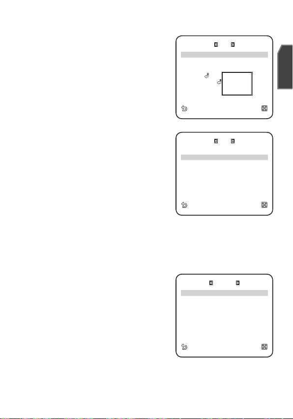
CAMERA ID
Provide the ID and location for a camera that displays on the screen.
For selecting and saving each menu item, refer to “How to use the keyboard controller”. (page 18)
Select <CAMERA SET> - <CAMERA ID>.
1.
Use the joystick to select a desired character,
2.
then press [ENTER].
In the lower input box of the screen, the
selected character will be entered.
You can enter up to 54 characters including
alphabets, numbers and special characters.
y
LOCATION : Specify the display position
of the camera ID.
3.
When done, press [ENTER].
The camera ID will be displayed in the specifi ed position.
VPS
If you set it to <ON>, the camera images will be displayed in progressive mode.
W
CAMERA SET
CAMERA ID OFF
VPS OFF
IRIS ALC
MOTION (F.FAST)
DNR MID
SHUTTER (OFF)
SENS-UP AUTO X4
FLICKERLESS OFF
XDR MID
CAMERA ID
A
BCDEFGHIJKLMNOPQRSTUVWXYZO
123456789
: ?
XX
WW
SP
SP LOCATION
-
- - - - - - - - - - - - - - - - - - - - - - - - - - - - - - - -
- - - - - - - - - - - - - - - - - - - - - - - - - - - - - - - - -
X
_
¾
+
()/
---
---
22_ setup
IRIS
ALC
BACKLIG HT BLC
AREA USER
<SIZE>
<LOCATION>
ALC
LEVEL
[
00
]
----
----
WEIGHT MID
WDR LEVEL
[
0
]
----
----
WHITE BAL INDOOR
MANUA L
The IRIS menu is useful if you set to adjust the
intensity of radiation incoming to the camera.
y
ALC : Adjust the open and close of the iris.
- LEVEL : Select an overall brightness level.
- BLC : With <BACKLIGHT> set to
<BLC>, you can specify the BLC area.
With AREA set to <USER>, you can
specify the position and size.
ALC
LEVEL
BACKLIGHT BLC
AREA USER
<SIZE>
<LOCATION>
[
00]
----I----
English
- WDR : If you set <BACKLIGHT> to
<WDR>, you will see a menu where you
can set the WDR options.
Specify the shutter speed in WDR LEVEL,
and, the composition level in <WEIGHT>.
Select OUTDOOR, or INDOOR in
<WHITE BAL>.
LEVEL
BACKLIGHT WDR
WEIGHT MID
WDR LEVEL
WHITE BAL INDOOR
ALC
[
]
00
----II
[
]
0
----II
The WDR feature provides an extension of
the gain range, which is useful, especially
if you work on pictures both indoors and
outdoors from inside of a building.
Namely, it improves the sharpness of the picture in outdoor scenery as well as
indoor.
As long as you use the VPS function, the WDR will not be available as the CCD read
M
method differs accordingly. If you set VPS to ON, WDR will be set to <OFF>
accordingly.
y
MANUAL : Adjust the iris level manually.
The overall brightness target of a camera
M
will be set to ALC level 0, while the iris
LEVEL
MANUAL
[ 00]
----I----
can be adjusted manually.
English _23
----
----
setup
W
CAMERA SE T
X
CAMERA ID OFF
VPS
OFF
IRIS ALC
DNR MID
SHUTTER
OFF
SENS-UP
OFF
FLICKER LESS
OFF
XDR MID
AGC
With this, you can adjust the AGC level of a
camera.
With AGC active, if the signal strength falls
below the standard level, AGC will amplify the
video signal to automatically improve the
sensitivity.
If <SENS-UP> is set to <OFF>, or <FIX>
mode, the <MOTION> menu will switch to
<AGC>.
With the USER
( )
submenu selected, press
[ENTER] to display the corresponding screen.
In this mode, you can select from VERY LOW
to VERY HIGH in 16 levels, enabling deeper, wider choices to your convenience.
With the FIX
screen. In this mode, you can select an individualized mode in 16 levels, regardless of
()
submenu selected, press [ENTER] to display the corresponding
the brightness.
As long as the DAY/NIGHT menu is set to AUTO in Camera Setup, the AGC menu is
M
not available.
As long as FLICKERLESS is set to ON, the AGC mode is not available.
If you set BACKLIGHT to WDR, the AGC fi x mode is not available.
MOTION
You can specify a level of AGC for controlling the camera motion.
This is available only of the SENSE UP menu is set to AUTO.
Select F.FAST if you want to monitor a very fast moving object in a low contrast
scene, and S.SLOW if monitoring a very slow moving, inanimate object in the same
condition.
As long as DAY/NIGHT is set to <AUTO>, the <MOTION> menu is not available.
W
CAMERA SET
CAMERA ID OFF
VPS
IRIS ALC
AGC (VERY HIGH)
DNR MID
SHUTTER
SENS-UP
FLICKERLESS
XDR MID
X
OFF
---
OFF
OFF
OFF
DNR
Reduces the noise on the camera image.
The higher the level is, the greater the effect is.
Set it to <USER> to specify the level.
24_ setup

SHUTTER
W
CAMERA SE T
X
CAMERA ID OFF
VPS
OFF
IRIS ALC
AGC (VERY HIGH)
---
DNR MID
SENS-UP (
OFF
---
FLICKER LESS (
OFF
---
XDR MID
You can select a fixed fast electronic shutter
speed in 7 options ranging from 1/120 to 1/10k,
which is mostly used to take a picture of a fast
moving object.
As long as SENSE UP is set to AUTO, FIXED /
FLICKERLESS to ON / BACKLIGHT to WDR, the
SHUTTER menu is not available.
W
CAMERA SET
CAMERA ID OFF
VPS
IRIS ALC
AGC (VERY HIGH)
DNR MID
SHUTTER 1/120
SENS-UP (
FLICKERLESS (
XDR MID
X
OFF
---
OFF) )
---
OFF) )
---
SENS-UP
Automatically senses the darkness level at night or in a low contrast scene, and
extends the accumulation time accordingly; you can select <AUTO> or <FIX> for a
bright and sharp image.
If the SHUTTER menu is set to fi xed electronic shutter mode, the SENSE UP menu
M
will not be available.
If FLICKERLESS is set to ON, or BACKLIGHT to WDR, the FIX mode of the SENSE UP
menu is not available.
FLICKERLESS
This will prevent possible screen distortion due to a mismatch between the vertical
sync frequency and the blinking frequency of the lighting; if set to <ON>, the shutter
speed will be fixed to 1/120 second.
If SHUTTER is set to FIX, SENSE UP to FIX, and AGC to FIX, the <FLICKERLESS> menu is
not available.
XDR
This will correct a brightness difference between different scenes for the optimal
visibility by calculating the ambient luminance contrast in a certain unit of pixels.
The higher the value is, the higher the correction level is.
English
English _25
setup
AUTO
DAY
¨
NIGHT
BRIGHTNESS MID
DWELL TIME 2SEC
NIGHT
¨
DAY
BRIGHTNESS MID
DWELL TIME 5SEC
MASK AREA
1 2
MASK AR EA
<LOCATION>
WHITE B AL
FOCUS M ODE ONEAF
ZOOM SP EED [
2
]
DISPLAY ZOOM OF F
DISPLAY P/T OFF
DIGITAL ZOOM OFF
DETAIL [
2
]
V-SYNC INT
DAY/NIGHT
You can specify a recording mode according to the scene.
For selecting and saving each menu item, refer to “How to use the keyboard controller”. (page 18)
Select <CAMERA SET> - <DAY/NIGHT>.
1.
Select a screen transition mode according
2.
to the illumination, and set options as
appropriate.
y
DAY : Fixed to DAY mode, regardless of
the scene.
y
NIGHT : Fixed to NIGHT mode,
regardless of the scene.
If BURST is set to <ON>, the burst
signal will be output along with the
black-and-white composite video signal.
y
AUTO : According to the luminance, this
will switch DAY to NIGHT mode, or vice
versa.
-
BURST : If set to <OFF>, the burst
signal will not be output in NIGHT mode.
-
DAY¨NIGHT BRIGHTNESS : Specify
the brightness level switching from
COLOR to BW fi lter.
Adjusting from HIGH to LOW will cause
to switch the fi lter in a darker screen.
-
DAY¨NIGHT DWELL TIME : Time
required to determine the fi lter switch.
-
NIGHT¨DAY BRIGHTNESS : Specify the brightness level switching from
BW to COLOR fi lter. Adjusting from HIGH to LOW will cause to switch the
fi lter in a darker screen.
-
NIGHT¨DAY DWELL TIME : Time required to determine the fi lter switch.
-
MASK AREA : If there exists a bright
spot light source in a night scene, you
can specify the size and position as
needed.
This will prevent an error in switching
fi lter, or failure to determine the fi lter
switch in a night scene where a bright
spot light source exists.
Any excessively bright area in a night
scene will be MASKed.
DAY/NIGHT AUTO
WHITE BAL
FOCUS MODE ONEAF
ZOOM SPEED [
DISPLAY ZOOM OFF
DISPLAY P/T OFF
DIGITAL ZOOM OFF
DETAIL [
V-SYNC INT
AUTO
BURST OFF
¨
DAY
NIGHT
BRIGHTNESS MID
DWELL TIME 2SEC
¨
NIGHT
DAY
BRIGHTNESS MID
DWELL TIME 5SEC
MASK AREA
MASK AREA
<SIZE>
<LOCATION>
]
2
]
2
1 2
26_ setup
You can specify MASK 1 and 2 simultaneously.
If <BACKLIGHT> is set to <BLC>, the MASK AREA function is not available.
y
EXT : The interface to an external alarm enables an automatic switch between
DAY and NIGHT mode.
If you set <DAY/NIGHT> to EXT, and alarm #1 to NO/NC in ALARM SETALARM IN SET, the alarm can be used for an input signal in EXT mode of
<DAY/NIGHT>.
If an alarm signal occurs, the mode will switch to NIGHT.
If <DAY/NIGHT> is set to EXT, ALARM1 in ALARM OUT SET, and ALARM1 in ALARM
M
SET-AUTO SET are not available.
If you use an infrared light source while in AUTO mode, this may cause a failure in
AUTO SWITCH or AUTO FOCUS.
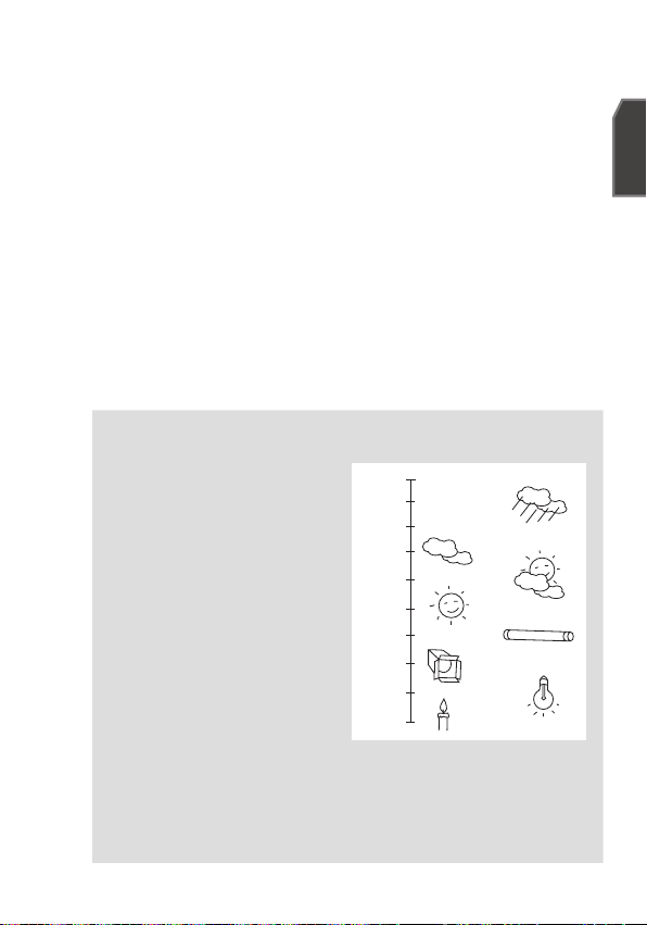
WHITE BAL
If you need to adjust the color according to the ambient illumination, you can use
the <WHITE BAL> function.
For selecting and saving each menu item, refer to “How to use the keyboard controller”. (page 18)
Illumination is generally referred to as color temperature, which is represented in a
measurement of kelvin (K). Color temperatures for ordinary lighting are as follows:
In the <WHITE BAL> menu, you
can set a mode for correcting the
<WHITE BAL>.
- ATW1,2 : If you set the <WHITE
BAL> menu to <ATW1> or
<ATW2> mode, this will monitor
the change of the color temperature
to correct the <WHITE BAL> as
needed.
The following color temperature
ranges are assured in individual
modes:
ATW1 : 2500K ~ 9300K (Ú1)
ATW2 : 2000K ~ 10000K
(suitable to sodium light source) (Ú2)
With <ATW1> mode active in a color temperature environment ranging
1 :
Ú
beyond between 2500K and 9300K, a proper white balance value may not be
produced; if this is the case, you are recommended to use <ATW2> mode.
2 : With <ATW2> mode active in a mostly single color environment, the display
Ú
color and the actual one may differ; so select a mode as appropriate to your
color temperature environment.
10000K
9000K
8000K
7000K
6000K
5000K
4000K
3000K
2000K
1000K
Blue sky
Cloudy
Sunny
Halogen lamp
Candlelight
Rainy
Partly Cloudy
Fluorescent lamp
Tungsten lamp
English
English _27
setup
WHITE BAL
DAY/NIGHT NIGHT
BRIGHTN ESS MID
RED
[
00
]
----
I
----
BLUE
[
00
]
----
I
----
R-GAIN
[
0064
]
B-GAIN
[
0064
]
WHITE BAL
DAY/NIGHT DAY
RED
[
00
]
----
I
----
BLUE
[
00
]
----
I
----
R-GAIN
[
0064
]
B-GAIN
[
0064
]
Select <CAMERA SET> - <WHITE BAL>.
1.
Select a mode where you set the <WHITE BAL>.
2.
y
DAY : You can set the RED, and BLUE
value in DAY mode.
The screen will be displayed in colors
according to your settings.
You can set the R-GAIN, and B-GAIN value
only in <AWC> mode.
If AGC is set to <OFF> or <FIX>, the NIGHT
menu can not be accessed.
y
NIGHT : You can set the <WHITE BAL>
according to the ambient illumination.
If NIGHT mode is set to <OFF>, the
<WHITE BAL> will operate in a mode
specifi ed in DAY mode at all times;
otherwise, the screen will switch to a
mode specifi ed in <DAY/NIGHT>.
You can set the RED, BLUE and
BRIGHTNESS value in DAY mode.
The screen will be displayed in colors
according to your settings.
3.
According to the specifi ed recording mode, select a <WHITE BAL> mode with
necessary options.
y
ATW1,2 : The camera can automatically adjust the color temperature in real
time, according to the ambient conditions.
(Color temperature range 1: 2500K ~ 9300K, 2 : 2000K ~ 10000K)
y
AWC : Pressing [ENTER] on a desired item will perform ATW once.
You can set the R-GAIN/B-GAIN value.
y
3200K : Set the color temperature to 3200K.
y
5600K : Set the color temperature to 5600K.
-
BRIGHTNESS : Specify a brightness level switching from DAY mode to
NIGHT mode setting.
-
RED : Adjust the strength of the red color.
-
BLUE : Adjust the strength of the blue color.
-
R-GAIN/B-GAIN : Specify the current color temperature manually.
WHITE BAL
DAY/NIGHT DAY
MODE AWC
RED
BLUE
[
R-GAIN
[
B-GAIN
WHITE BAL
DAY/NIGHT NIGHT
BRIGHTNESS MID
MODE AWC
RED
BLUE
[
R-GAIN
[
B-GAIN
[
[
0064
0064
[
[
0064
0064
----
----
]
I
00
----
----
]
I
00
]
]
----
----
]
I
00
----
----
]
I
00
]
]
28_ setup

FOCUS MODE
DAY/NIGHT AUTO
WHITE B AL
ZOOM SP EED
[2]
DISPLAY ZOOM OF F
DISPLAY P/T OFF
DIGITAL ZOOM X16
DETAIL [2]
V-SYNC INT
You can select a focus mode according to the
angle that you adjusted for camera recording.
- AF : This will monitor the screen continuously
to focus automatically. If you adjust the focus
manually, that will operate the same as in
<MF>. This will also restore focus after the
operation of pan/tile/zoom.
- ONEAF : Restores focus after the operation
of pan/tile/zoom, and operates the same as
DAY/NIGHT AUTO
WHITE BAL
FOCUS MODE ONEAF
ZOOM SPEED
DISPLAY ZOOM OFF
DISPLAY P/T OFF
DIGITAL ZOOM X16
DETAIL [2]
V-SYNC INT
[2]
in <MF> unless the operation of pan/tile/
zoom is executed.
- MF : You can adjust the focus manually.
While you are working on the following objects, <AF> may not work properly.
M
If this is the case, use <MF> instead.
- Very bright object, or dominant object in a dark scene
- Object against the rear side of a moist or dirty glass
- A scene where nearby and distant objects co-exist
- White wall or single-colored object
- Venetian blinds and other horizontally striped objects
ZOOM SPEED
You can adjust the zoom operation speed.
DISPLAY ZOOM
You can set to display the zoom status on the screen.
It will disappear in about 3 seconds if the zoom factor has no further change.
DISPLAY P/T
You can set to display the operation status of pan/tilt when it is active.
It will disappear in about 3 seconds if the pan/tilt position has no further change.
However, the allowable error is ±2°.
DIGITAL ZOOM
You can set the maximum allowable digital zoom ratio.
Digital Zoom will start operation after it is zoomed in to the maximum optical ratio of
x25. If you set DIGITAL ZOOM to x16, you can take a shot at up to x400 (43x16).
English
DETAIL
Used to adjust the vertical and horizontal distinction, respectively.
English _29
setup
REVERSE OFF
POSI/NE GA +
PIP OFF
DIS OFF
V-SYNC
You can set the V-SYNC mode.
- If you select <INT>, the camera will use the internal synchronization.
- If selecting <LINE>, the camera will use an external power frequency for
synchronization. The LL-PHASE can be adjusted as appropriate.
AGC COLOR SUP
You can adjust the color reproduction range
according to AGC.
REVERSE
You can reverse the video signal from left
to right, upside down, or vice versa to your
convenience.
POSI/NEGA
You can set the video brightness signal to normal or reverse.
PIP
You can view a main image with a sub image on the same screen.
If more than one PRIVACY ZONE is specifi ed, and PRIVACY SET to <ON>, the PIP
M
function is not available.
As long as SENSE UP is set to FIXED, PIP menu is not available.
According to the luminance, PIP will disappear if the SENSE UP menu is set to AUTO.
DIS (Digital Image Stabilization)
If you set it to <ON> for a camera that is trembled or vibrated from an ambient
change, this will automatically compensate for the flicker on the screen.
AGC COLOR SUP MID
REVERSE OFF
POSI/NEGA +
PIP OFF
DIS OFF
M
30_ setup
If you set <DIS> to <ON>, the image will be enlarged with digital zoom as much
area as compensated. (Approximately 1.2 times of the optical zoom factor)
If you set the digital zoom to a larger ratio than the actual enlargement for
compensation, the <DIS> function will be disabled.
<DIS> may not work properly in the following images:
Single-colored fl at image / Low contrast scene / High frequency image taken under
a fl uorescent lamp / Regular-patterned image

INTELLIGENT VIDEO
MOTION OFF
ADVANCED OFF
MASK AREA
1 2 3 4
DISPLAY ON
SENSITI VITY
[
4
]
RESOLUT ION
[
3
]
ALARM O UT
MASK AR EA
<LOCATION>
You can enable the motion detection and tracking functions.
For selecting and saving each menu item, refer to “How to use the keyboard controller”. (page 18)
Select <MAIN MENU>-<INTELLIGENCE>.
1.
Select each item and set appropriately.
2.
MOTION
You can enable the motion detection and
tracking functions.
If you set it to <DETECTION>, the
M
<FIXED/MOVED> option of ADVANCED
menu will not be available.
In following situations, motion detection and tracking function may not work properly.
- When there is sudden changes of brightness
- When the device moves
- When a certain object’s movement fi lls most of the framing area
- When there is diffi culties in distinguishing the moving object and background
ADVANCED
You can detect motions and mark the video that contains such motion, and enables
tracking of the movement. (The auto PTZ function is not supported for tracking an object.)
Selecting the <FIXED/MOVED> option will mark a region if an existing object
disappears, or a new object appears and fixed for a certain period of time.
In following situations, FIXED/MOVED detection may not work properly.
M
- When multiple motions continue arbitrarily.
- When the object that is fi xed continues to move in the same position.
- When a newly appearing object conceals another object that is moving.
MASK AREA
Select the number of the area to be
1.
masked that will be excluded from motion
detection.
2.
Select the mask number and set the mask
size and its coverage.
W
INTELLIGENCE
MOTION OFF
ADVANCED OFF
MASK AREA
DISPLAY ON
[
SENSITIVITY
[
RESOLUTION
ALARM OUT
MASK AREA
<SIZE>
<LOCATION>
X
1 2 3 4
]
4
]
3
English
English _31

setup
1 2 3 4 5 6
7 8 9 10 11 12
PRIVACY SET
ON
STYLE
MOSAIC1
ALARM O UT
FIXED/M OVED ON
DISPLAY
When selected <ON>, it displays the motion detected and detection of configured
advanced function.
SENSITIVITY
Sets the sensitivity of motion sensor.
RESOLUTION
The bigger the resolution setting, the smaller the object that can be detected.
ALARM OUT
When selected <ON>, it outputs alarm
signal when the motion is detected and on a
ALARM OUT
MOTION ON
FIXED/MOVED ON
detection of configured advanced function.
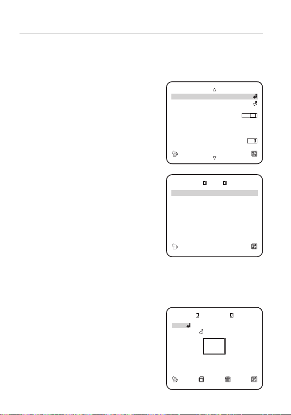
PRIVACY ZONE
You can set up to 12 privacy zones that will be hided for privacy of the subject when
recording.
Zone Setup
For selecting and saving each menu item, refer to “How to use the keyboard controller”. (page 18)
Select <MAIN MENU>-<PRIVACY ZONE>.
1.
Select the number of the zone and press
2.
[ENTER].
The Zone setup screen appears.
3.
Select the <SET P/T/Z> and press
[ENTER].
Using the joystick, adjust the camera’s
pan, tilt and zoom.
32_ setup
W
PRIVACY ZONE
1 2 3 4 5 6
7 8 9 10 11 12
PRIVACY SET
STYLE
X
MOSAIC1
ON

Select the <PIXEL LEVEL>.
PRIVACY ZO NE SET 1
PIXEL LE VEL [
4
]
<SIZE>
<LOCATION>
¾¾
MAIN M ENU
¾¾
PROFILE
CAMERA SE T
INTELLI GENCE
PRIVACY ZONE
AUTO SET
ZONE SE T
ALARM S ET
CLOCK S ET
OTHER S ET
4.
Select the pixel level for the SIZE and
LOCATION settings.
5.
Select the <SIZE> and press [ENTER].
Using the joystick, set the size of the
privacy zone.
6.
Select the <LOCATION> and press
PRIVACY ZONE SET 1
<SET P/T/Z>
PIXEL LEVEL [
<SIZE>
<LOCATION>
]
4
[ENTER].
Using the joystick, set the position of the
privacy zone.
7.
Save the changes and move to the
previous screen and select the <STYLE>.
Select the <COLOR> and pick a desired color.
Setting one or more privacy zone and enabling privacy function will disable the PIP
M
function.
For better privacy protection, make your privacy zone bigger than the required,
bigger by about 30%.
Video portion of mosaic pattern or colored by the privacy zone setup is not
recoverable.
PRESET
This function provides preset camera settings such as pan, tilt, zoom and focus so to
enable quicker and easier accessing and monitoring, which supports up to 512 presets.
For selecting and saving each menu item, refer to “How to use the keyboard controller”. (page 18)
Select <MAIN MENU>-<PRESET>.
1.
¾¾
MAIN MENU
PROFILE
CAMERA SET
INTELLIGENCE
PRIVACY ZONE
PRESET
AUTO SET
ZONE SET
ALARM SET
CLOCK SET
OTHER SET
¾¾
English
English _33

setup
0
¾
1 2 3 4
5 6 7 8 9
10 11 12 13 14
15 16 17 18 19
20 21 22 23 24
25 26 27 28 29
30 31
W
1/16
X
PRESE T NO. 1
PRESET ID O N
PRESET SPEED [
5
]
DWELL TI ME 3SEC
IMAGE H OLD O FF
CAMERA SE T ON
CAMER A SET
WHITE B AL
FOCUS M ODE MF
Select the preset number.
2.
0
5 6 7 8 9
10 11 12 13 14
15 16 17 18 19
20 21 22 23 24
25 26 27 28 29
30 31
Select <POSITION> and adjust <PAN/
3.
TILT/ZOOM> to the desired setup using
the joystick.
Set <PRESET ID> to <ON> and enter the
4.
name.
For entering the name, refer to “CAMERA ID”.
(page 22)
Select <PRESET SPEED> and adjust the
5.
pan/tilt speed of the preset.
Set the <DWELL TIME> that defi nes the
6.
camera's hold duration and <IMAGE HOLD> of the preset.
If you set the <IMAGE HOLD> to <ON>, the video image will be held still until the
camera reaches the preset position.
Set <CAMERA SET> to <ON>.
7.
You can adjust camera setups for each
preset.
For details on setting <IRIS>, <WHITE BAL>
and <FOCUS MODE>, refer to “CAMERA
SET”. (pages 22 ~ 30)
POSITION
PRESET ID ON
PRESET SPEED [
DWELL TIME 3SEC
IMAGE HOLD OFF
CAMERA SET ON
IRIS ALC
WHITE BAL
FOCUS MODE MF
W
X
PRESET
¾
1 2 3 4
1/16
W
X
PRESET NO. 1
5
CAMERA SET
]
M
34_ setup
If VPS is set to ON in Camera Setup from
the main menu, the camera will operate in
VPS even if it's set to WDR in PRESET.
If you use WDR in PRESET, the camera will operate in WDR and release any previous
settings even if AGC has been set to FIX, SHUTTER to ON, SENSE UP to FIX in the
main menu.

The preset position can be specifi ed for a tilt range of between -6° and 90°.
AUTO PAN
1 2 3 4
PATTERN
1
¾
2
¾
3
¾
SCAN
1 2 3 4
AUTO PLAY OFF
¾¾
MAIN M ENU
¾¾
PROFILE
CAMERA SE T
INTELLI GENCE
PRIVACY ZONE
PRESET
ZONE SE T
ALARM S ET
CLOCK S ET
OTHER S ET
Those presets that are out of a tilt of 90° can not be specifi ed.
If you try to specify a preset position for a range exceeding a tilt of 90° using a
controller (SSC-1000, 2000 or 5000), you will see a message of <SET AGAIN> on
the screen. If this is the case, try again for a range below a tilt of 90°.
If you upload/download the menu setting using SSC-1000, 2000 or 5000, the preset
may differ from the menu setting so defi ne the preset again after the operation.
AUTO SET
You can set the AUTO PAN, PATTERN, and AUTO PLAY.
If you upload/download the menu setting using SSC-1000, 2000 or 5000, the
M
settings for AUTO PAN, PATTERN, SCAN, and PRESET may differ from the menu
settings so defi ne them again after the operation.
Auto Pan Setup
Set the starting and ending positions to patrol between points at specified speed.
For selecting and saving each menu item, refer to “How to use the keyboard controller”. (page 18)
Select <MAIN MENU>-<AUTO SET>.
1.
Select the number of <AUTO PAN>.
2.
AUTO PAN setup screen appears.
¾¾
CAMERA SET
INTELLIGENCE
PRIVACY ZONE
W
AUTO PAN
PATTERN
SCAN
AUTO PLAY OFF
MAIN MENU
PROFILE
PRESET
AUTO SET
ZONE SET
ALARM SET
CLOCK SET
OTHER SET
AUTO SET
1 2 3 4
1 2 3 4
¾¾
X
1
English
2
3
¾
¾
¾
English _35

setup
AUTO PAN 1
DIRECTI ON LEFT
ENDLESS OFF
SPEED
[10]
DWELL TI ME 3SEC
Select each item and set appropriately.
3.
y
POSITION : Set the starting and ending
positions for the <AUTO PAN>.
Move to the setting screen and adjust
pan/tilt to the desired starting position,
and then press [ENTER].
Again, adjust pan/tilt to the desired
ending position and press [ENTER] to
fi nish <AUTO PAN> setup.
y
DIRECTION : Sets the direction of the camera’s movement from the starting to
the end position. (Based on panning)
<RIGHT><LEFT>
START START
AUTO PAN 1
POSITION
DIRECTION LEFT
ENDLESS OFF
SPEED
DWELL TIME 3SEC
[10]
END
y
ENDLESS : Instead of shuttling between start and end positions, the camera
END
turns 360° endlessly while stops for the <DWELL TIME> at both positions.
y
SPEED : Sets the moving speed of the camera, from 1 to 64.
y
DWELL TIME : Sets the dwell time at the starting and ending positions, from
1 to 60 seconds.
36_ setup

Pattern Setup
¾
S
¾
PATTERN SET 1
START
PATTERN SET 1
<POSITI ON>
SCAN 1
¾
S 1 2 3 4
5 6 7 8 9
10 11 12 13 14
15 16 17 18 19
20 21 22 23 24
25 26 27 28 29
30 31
W
1/16
X
You can manually record your pan/tilt/zoom movements to a monitoring pattern for
up to 2 minutes.
For selecting and saving each menu item, refer to “How to use the keyboard controller”. (page 18)
1.
Select <MAIN MENU>-<AUTO SET>.
2.
Select the pattern number.
PATTERN setup screen appears.
3.
Select the <POSITION> and set the
<POSITION>
START
PATTERN SET 1
pattern's starting position and press
[ENTER].
4.
Select the <START> and move the
camera using pan/tilt/zoom.
5.
Your manual camera actions will be
recorded for up to 2 minutes, and returns
<POSITION>
START
PATTERN SET 1
to the previous menu automatically.
To stop manual recording and return to the
previous menu before 2 minutes, press
[ENTER].
Scan Setup
You can set the SCAN operation to include a defined preset position.
For selecting and saving each menu item, refer to “How to use the keyboard controller”. (page 18)
Select <MAIN MENU>-<AUTO SET>.
1.
Select the scan number.
2.
SCAN setup screen appears.
3.
Move the cursor to a number with the [
mark which contains a defi ned preset.
Press [ENTER].
4.
S] mark appears beside the [
[
corresponding preset is included in the
] and the
¾
scan.
0
5 6 7 8 9
10 11 12 13 14
]
¾
15 16 17 18 19
20 21 22 23 24
25 26 27 28 29
30 31
SCAN 1
¾
S 1 2 3 4
1/16
W
X
English
SCAN numbers confi gured for a certain page can be saved only in the corresponding
M
page. Make sure to save it before moving to the next page.
English _37

setup
AUTO PLAY 1
AUTO PLAY PRESE T
PLAY NUMBER 0
W
AUTO SET
X
AUTO PAN
1 2 3 4
PATTERN
1
¾
2
¾
3
¾
SCAN
1 2 3 4
AUTO PLAY 2
ID: START EN D PLAY NO.
00:00 03: 00 OFF 0
2 03:00 06 :00 OFF 0
3 06:00 09 :00 OFF 0
4 09:00 12 :00 OFF 0
5 12:00 15 :00 OFF 0
6 15:00 18 :00 OFF 0
7 18:00 21 :00 OFF 0
8 21:00 00 :00 OFF 0
Auto Play Setup
AUTO PLAY runs configured AUTO PAN, PATTERN, and SCAN functions
automatically.
For selecting and saving each menu item, refer to “How to use the keyboard controller”. (page 18)
Select <MAIN MENU>-<AUTO SET>.
1.
Select the <AUTO PLAY> and select a
2.
number.
AUTO PLAY setup screen appears.
y
AUTO PLAY1 : Sets overall function
properties of the AUTO PLAY.
AUTO RETURN : Sets the interval
between auto plays.
AUTO PLAY : Sets the auto play action
at every auto play interval.
You can set between 1 ~ 4 for SCAN
or AUTO PAN, 1 ~ 3 for PATTERN, and
0 ~ 511 for PRESET.
PLAY NUMBER : Sets the number of
the defi ned auto play operation.
y
AUTO PLAY2 : Select the auto play
action and set its starting / ending time.
When the time hits the defi ned starting
time, confi gured auto play will begin.
You can set between 1 ~ 4 for SCAN or
AUTO PAN, 1 ~ 3 for PATTERN, and
0 ~ 511 for PRESET.
W
AUTO PAN
PATTERN
SCAN
AUTO PLAY 1
AUTO PLAY 1
AUTO RETURN 1MIN
AUTO PLAY PRESET
PLAY NUMBER 0
AUTO PLAY 2
ID: START END PLAY NO.
1
00:00 03:00 OFF 0
2 03:00 06:00 OFF 0
3 06:00 09:00 OFF 0
4 09:00 12:00 OFF 0
5 12:00 15:00 OFF 0
6 15:00 18:00 OFF 0
7 18:00 21:00 OFF 0
8 21:00 00:00 OFF 0
AUTO SET
1 2 3 4
1 2 3 4
X
1
2
3
¾
¾
¾
38_ setup

ZONE SET
AZIMUTH OFF
ZONE AREA S ET OFF
¾¾
MAIN M ENU
¾¾
PROFILE
CAMERA SE T
INTELLI GENCE
PRIVACY ZONE
PRESET
AUTO SET
ALARM S ET
CLOCK S ET
OTHER S ET
ZONE AR EA MAP
2 3 4
5 6 7 8
You can set the north direction and the zone coverage.
For selecting and saving each menu item, refer to “How to use the keyboard controller”. (page 18)
Select <MAIN MENU>-<ZONE SET>.
1.
Set <AZIMUTH> to <ON>.
2.
Set the north direction using the joystick
3.
and press [ENTER].
y
SET NORTH : In SET NORTH, press
[ENTER] to set the north direction
which will be the reference for all other
directions.
Set <ZONE AREA SET> to <ON>.
4.
When the <ZONE AREA MAP> screen
5.
appears, select a number.
When the <ZONE AREA SET> screen
6.
appears, set the <POSITION> and
<ZONE ID SET>.
For entering the name, refer to “CAMERA ID”.
(page 22)
y
POSITION : Sets the left/right boundaries
of the zone.
¾¾
CAMERA SET
INTELLIGENCE
PRIVACY ZONE
W
AZIMUTH OFF
ZONE AREA SET OFF
ZONE AREA MAP
1
2 3 4
5 6 7 8
MAIN MENU
PROFILE
PRESET
AUTO SET
ZONE SET
ALARM SET
CLOCK SET
OTHER SET
ZONE SET
¾¾
X
English
English _39

setup
ALARM P RIORITY SET
ALARM I N SET
ALARM O UT SET
AUTO SET
AUX OUT CONTRO L
¾¾
MAIN M ENU
¾¾
PROFILE
CAMERA SE T
INTELLI GENCE
PRIVACY ZONE
PRESET
AUTO SET
ZONE SE T
CLOCK S ET
OTHER S ET
ALARM P RIORITY SET
ALARM2 2
ALARM3 3
ALARM4 4
ALARM5 5
ALARM6 6
ALARM7 7
ALARM8 8
ALARM SET
It provides 8 alarm inputs and 3 alarm outputs. Detects alarm inputs from the external
sensors cooperating with configured presets, patterns, and scan functions, and
produces alarm outputs. Alarm’s dwell time is defined by the corresponding preset’s
<DWELL TIME> and its alarm action.
For selecting and saving each menu item, refer to “How to use the keyboard controller”. (page 18)
Select <MAIN MENU>-<ALARM SET>.
1.
Select each item and set appropriately.
2.
y
ALARM PRIORITY : Sets the priorities of
alarms. Setting the priorities of 8 alarms
defi nes the alarm notifi cation priorities
of them in the highest orders.
By default, the priorities are set as
Alarm 1 ¨ Alarm 2 ¨ ..... ¨ Alarm 8.
When multiple alarms are generated
at the same time, alarm notifi es in the
order of the default priority setting.
While an alarm is generating, no motion
is detected.
¾¾
CAMERA SET
INTELLIGENCE
PRIVACY ZONE
W
ALARM PRIORITY SET
ALARM IN SET
ALARM OUT SET
AUTO SET
AUX OUT CONTROL
ALARM PRIORITY SET
ALARM1 1
ALARM2 2
ALARM3 3
ALARM4 4
ALARM5 5
ALARM6 6
ALARM7 7
ALARM8 8
MAIN MENU
PROFILE
PRESET
AUTO SET
ZONE SET
ALARM SET
CLOCK SET
OTHER SET
ALARM SET
¾¾
X
40_ setup

y
AUX OUT CONTRO L
OUT2 OFF
OUT3 OFF
AUTO SET
ALARM2 OFF
ALARM3 OFF
ALARM4 OFF
ALARM5 OFF
ALARM6 OFF
ALARM7 OFF
ALARM8 OFF
MOTION OFF
ALARM IN SET : Select the alarm sensor operation between <NO>, <NC> and
<OFF>.
y
ALARM OUT SET : Set the alarm out port matched to the alarm input port.
y
AUTO SET : Sets the pattern and scan
action for the corresponding alarm
input. When the alarm is generated, the
camera moves to the preset position
coupled to the corresponding alarm.
Presets 1 ~ 8 are coupled with alarms
1 ~ 8 inputs respectively, and the preset
9 is coupled to the motion detection.
The camera stops and remains in the
ALARM1 OFF
ALARM2 OFF
ALARM3 OFF
ALARM4 OFF
ALARM5 OFF
ALARM6 OFF
ALARM7 OFF
ALARM8 OFF
MOTION OFF
AUTO SET
corresponding preset position for the
defi ned <DWELL TIME>, and performs
pattern or scan action defi ned by the <AUTO SET>. Setting to <OFF> will
discard with the pattern or scan action after moving to the preset position.
- PATTERN 1 ~ 3 : Defi ned pattern action
- HALF1 : Patterns 1 and 2 in serial action
- HALF2 : Patterns 2 and 3 in serial action
- WHOLE : Patterns 1, 2 and 3 in serial action
- SCAN 1 ~ 4 : Predefi ned SCAN action
The <ALARM1> is used as external switching signal if the <DAY/NIGHT> is set to
M
<EXT>.
y
AUX OUT CONTROL : Sets whether to
sustain the alarm output despite of the
alarm generation or to output alarm out
signal while the coupled alarm is alive.
When selected <OFF>, outputs alarm
AUX OUT CONTROL
OUT1 OFF
OUT2 OFF
OUT3 OFF
only if the alarm is generated. When
selected <ON>, it always outputs
alarm out signal despite of the alarm
generation.
English
English _41

setup
FACTORY DEFAULTS
OSD COL OR BW
PROPORT IONAL P/ T ON
P/T SPE ED
[
2
]
AUTO CAL . OFF
D-FLIP OFF
PASSWORD OFF
DISPLAY OFF
TIME FO RMAT 12HOUR
SET TIM E AM 07 :34:48
DATE FORMAT MM/DD/YYYY
SET DATE 01/01/2009
CLOCK SET
Sets whether to display the clock on the screen and its time format.
For selecting and saving each menu item, refer to “How to use the keyboard controller”. (page 18)
Select <MAIN MENU>-<CLOCK SET>.
1.
Select <DISPLAY> and set whether to
2.
display the time on the screen.
Select the time format and set the clock.
3.
Select the date format and set the date.
4.
OTHER SET
You can reset the system by running FACTORY DEFAULTS, or set the font color, zoom,
turbo pan/tilt, etc.
For selecting and saving each menu item, refer to “How to use the keyboard controller”. (page 18)
Select <MAIN MENU>-<OTHER SET>.
1.
Select each item and set appropriately.
2.
W
CLOCK SET
DISPLAY OFF
TIME FORMAT 12HOUR
SET TIME AM 07:34:48
DATE FORMAT MM/DD/YYYY
SET DATE 01/01/2009
W
OTHER SET
FACTORY DEFAULTS
OSD COLOR BW
PROPORTIONAL P/T ON
P/T SPEED
AUTO CAL. OFF
D-FLIP OFF
PASSWORD OFF
X
X
[
]
2
42_ setup

FACTORY DEFAULTS
FACTORY DEFAULTS
OK
PASSWORD
1 2 3 4
5 6 7 8 9
[
¾¾¾
]
[
¾¾¾¾
]
When selected, the <FACTORY DEFAULTS>
screen appears and you can reset all settings
to the factory default settings by selecting
the <OK>. However, the protocol, baud rate,
address and the language settings will not be
reset.
Note that the resetting the system to the
M
factory default will erase all settings data.
FACTORY DEFAULTS
OK
CANCEL
OSD COLOR
Selects the color of the on-screen display font.
PROPORTIONAL P/T
When selected <ON>, manual pan / tilt movement speed will vary proportionally to
the zoom ratio.
P/T SPEED
When selected <ON>, manual pan / tilt movement speed will be doubled.
AUTO CAL. (AUTO CALIBRATION)
To enhance the lens and pan/tilt motor’s accuracy, the automatic compensation
function is provided. It automatically resets the lens and pan/tilt when there is no
user operation for a specified time period.
D-FLIP (DIGITAL FLIP)
When selected <ON>, the displayed screen will be flipped vertically and horizontally
if the subject turns over 90°.
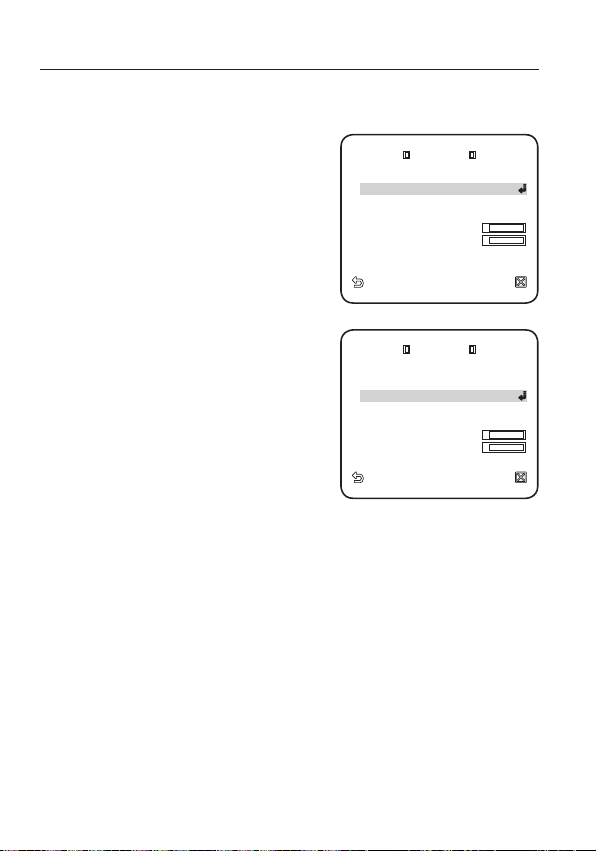
PASSWORD
When selected <ON>, it is asked to enter the
password for accessing the menu.
Select the numbers using direction keys and
press [ENTER].
The default password is “4321”.
PASSWORD
0
1 2 3 4
5 6 7 8 9
[
]
¾
¾¾¾
[
]
¾¾¾¾
English
English _43

setup
RS485
PRIORIT Y HW
PROTOCOL SAMSUNG
HALF
BAUD RATE 9600
ADDRESS 0
TYPE 4
_
PTZ
_
WDR
_
P
PROTOCOL SAMSUNG
ADDRESS 0
COMM. T YPE HW, R S485, HALF
BAUD RATE 9600
SERIAL N O. 000 000000000000
CAMERA VE R. v1.00
_
00000
ALARM V ER. v1.00
_
00000
COMMUNICATION
You can set the RS-485 communications setting in regard of the camera.
For selecting and saving each menu item, refer to “How to use the keyboard controller”. (page 18)
Select <MAIN MENU>-
1.
<COMMUNICATION>.
2.
Select each item and set appropriately.
y
PRIORITY : Set the priority by selecting
<HW> or <SW>.
When selected <HW>, the protocol,
baud rate and address settings will
follow those settings of the adaptor
switch.
y
PROTOCOL, BAUD RATE, ADDRESS :
When selected <SW>, you can manually
set the protocol, baud rate and address.
SYSTEM INFO
You can check the system information.
For selecting and saving each menu item, refer to “How to use the keyboard controller”. (page 18)
Select <MAIN MENU>-<SYSTEM INFO>.
1.
The current system information is displayed.
2.
W
COMMUNICATION
RS485
PRIORITY HW
PROTOCOL SAMSUNG
HALF
BAUD RATE 9600
ADDRESS 0
W
SYSTEM INFO
TYPE 4
PROTOCOL SAMSUNG
ADDRESS 0
COMM. TYPE HW, RS485, HALF
BAUD RATE 9600
SERIAL NO. 000000000000000
CAMERA VER. v1.00
ALARM VER. v1.00
X
X
_
_
PTZ
WDR
_
00000
_
00000
_
P
44_ setup

LANGUAGE
¾
ENGLISH
PУCCKNЙ
POLSKI
ČESKY
TÜRKÇE
You can set the language of the user interface.
For selecting and saving each menu item, refer to “How to use the keyboard controller”. (page 18)
Select <MAIN MENU>-<LANGUAGE>.
1.
Select your language using the up/down
2.
keys.
W
LANGUAGE
¾
ENGLISH
PУCCKNЙ
POLSKI
ČESKY
TÜRKÇE
X
English
English _45

appendix
appendix
SHORTCUT KEYS
Function Key
DAY/NIGHT - DAY [PRESET] + [5] + [1] + [2] + [ENTER]
DAY/NIGHT - NIGHT [PRESET] + [5] + [1] + [3] + [ENTER]
DAY/NIGHT - AUTO [PRESET] + [5] + [1] + [4] + [ENTER]
DAY/NIGHT - EXT [PRESET] + [5] + [1] + [5] + [ENTER]
IRIS – ALC – BACKLIGHT – WDR [PRESET] + [5] + [1] + [6] + [ENTER]
CAMERA SET
ALARM SET
OTHER SET
AUTO SET
Function Running A.C (Auto Calibration) [PRESET] + [5] + [3] + [8] + [ENTER]
IRIS – ALC – BACKLIGHT – OFF [PRESET] + [5] + [1] + [7] + [ENTER]
IRIS - ALC [PRESET] + [5] + [1] + [8] + [ENTER]
IRIS - MANU [PRESET] + [5] + [1] + [9] + [ENTER]
FOCUS MODE – AF [PRESET] + [5] + [2] + [0] + [ENTER]
FOCUS MODE – MF [PRESET] + [5] + [2] + [1] + [ENTER]
FOCUS MODE – ONEAF [PRESET] + [5] + [2] + [2] + [ENTER]
AUX OUT CONTROL – OUT1 – ON [PRESET] + [5] + [2] + [3] + [ENTER]
AUX OUT CONTROL – OUT1 – OFF [PRESET] + [5] + [2] + [4] + [ENTER]
AUX OUT CONTROL – OUT2 – ON [PRESET] + [5] + [2] + [5] + [ENTER]
AUX OUT CONTROL – OUT2 – OFF [PRESET] + [5] + [2] + [6] + [ENTER]
AUX OUT CONTROL – OUT3 – ON [PRESET] + [5] + [2] + [7] + [ENTER]
AUX OUT CONTROL – OUT3 – OFF [PRESET] + [5] + [2] + [8] + [ENTER]
PROPORTIONAL P/T – ON [PRESET] + [5] + [2] + [9] + [ENTER]
PROPORTIONAL P/T – OFF [PRESET] + [5] + [3] + [0] + [ENTER]
P/T SPEED – 9 [PRESET] + [5] + [3] + [1] + [ENTER]
P/T SPEED – 5 [PRESET] + [5] + [3] + [2] + [ENTER]
D-FLIP – ON [PRESET] + [5] + [3] + [3] + [ENTER]
D-FLIP – OFF [PRESET] + [5] + [3] + [4] + [ENTER]
AUTO PLAY – 1 [PRESET] + [5] + [3] + [5] + [ENTER]
AUTO PLAY – 2 [PRESET] + [5] + [3] + [6] + [ENTER]
AUTO PLAY – OFF [PRESET] + [5] + [3] + [7] + [ENTER]
46_ appendix

SPECIFICATIONS
Item Description
Product Type SMART DOME CAMERA
Power Source AC 24 V (50 Hz)
Power Consumption 11.5W
TV Standard PAL STANDARD COLOR SYSTEM
Image Sensor ExView-HAD PS CCD
Effective Pixels 752(H) × 582(V)
TV line frequency
Synchronization INT/LINE LOCK
Resolution
S/N Ratio Approximately 52 dB
Minimum subject
illumination
WDR x128
Signal Output COMPOSITE VIDEO OUT : 1.0 Vp-p 75 ohms/BNC
Lens
Horizontal : 15, 625 Hz (INT) / 15, 625 Hz (L/L)
Vertical : 50 Hz (INT) / 50 Hz (L/L)
Horizontal : 600 TV LINES
Vertical : 350 TV LINES
SENS-UP Illumination Color B/W
Off 50IRE 1.2 0.12
Off 30IRE 0.72 0.072
Off 15IRE 0.36 0.036
x512 50IRE 0.0023 0.00023
x512 30IRE 0.0014 0.00014
x512 15IRE 0.0007 0.00007
x25 Zoom Lens Integrated
Focal length : 3.66 ~ 91.36mm
Aperture : F1.65(Wide) F3.0(Tele)
- MOD(Minimum Object Distance) : 100mm
English
English _47

appendix
Item Description
PAN
TILT
Remote Control
Alarm
Operation Temperature -10°C ~ +50°C
Operation Humidity ~90%
Dimensions (Ø x H) 178 (Ø) x 219(H) mm
Weight 1.85 Kg
Product Color Light Gray
PAN range : 360˚Endless
Preset Pan Speed : 600˚/sec, maximum
Manual Pan Speed : 0.01˚~ 180˚/sec
Tilt range : -6˚~186˚
Preset Tilt Speed : 600˚/sec, maximum
Manual Tilt Speed : 0.01˚~ 180˚/sec
RS485(Half&Full Duplex)/RS422,
Data on Coaxial Cable
Alarm Inputs : 8 IN
Alarm Outputs : 3 OUT (2 Open collector 1 relay)
48_ appendix

PRODUCT APPEARANCE
English
English _49

Correct Disposal of This Product
(Applicable in the European Union and other European countries with separate collection systems)
This marking on the product, accessories or literature indicates that the product and its electronic accessories (e.g.
charger, headset, USB cable) should not be disposed of with other household waste at the end of their working life. To
prevent possible harm to the environment or human health from uncontrolled waste disposal, please separate these
items from other types of waste and recycle them responsibly to promote the sustainable reuse of material resources.
Household users should contact either the retailer where they purchased this product, or their local government
offi ce, for details of where and how they can take these items for environmentally safe recycling.
Business users should contact their supplier and check the terms and conditions of the purchase contract. This
product and its electronic accessories should not be mixed with other commercial wastes for disposal.
(Waste Electrical & Electronic Equipment)

SCC-C6415P
Камера Smart Dome
Руководство пользователя
удивительные возможности
Благодарим Вас за приобретение данного продукта
компании Samsung.
Для получения полного обслуживания посетите веб-сайт.
www.samsungsecurity.com

обзор
ВНИМАНИЕ
ОПАСНОСТЬ ПОРАЖЕНИЯ
ЭЛЕКТРИЧЕСКИМ ТОКОМ. НЕ ОТКРЫВАТЬ
ВНИМАНИЕ: ВО ИЗБЕЖАНИЕ ПОРАЖЕНИЯ ЭЛЕКТРИЧЕСКИМ ТОКОМ, НЕ СНИМАЙТЕ ЗАДНЮЮ КРЫШКУ.
ВНУТРИ НЕТ ДЕТАЛЕЙ, ОБСЛУЖИВАЕМЫХ ПОЛЬЗОВАТЕЛЕМ. ДЛЯ ТЕХНИЧЕСКОГО
ОБСЛУЖИВАНИЯ ОБРАЩАЙТЕСЬ К КВАЛИФИЦИРОВАННОМУ СПЕЦИАЛИСТУ.
Этот символ обозначает, что внутри устройства имеется
опасное напряжение, которое может привести к поражению
электрическим током.
Этот символ указывает, что в документации на изделие имеется
важная инструкция по его использованию или обслуживанию.
ПРЕДУПРЕЖДЕНИЕ
y
Во избежание повреждений, следствием которых может быть пожар или
поражение электрическим током, не допускайте попадания данного изделия под
дождь или в условия высокой влажности.
ПРЕДУПРЕЖДЕНИЕ
Пользуйтесь только стандартным блоком питания, который указан в листе
1.
спецификаций. Использование любого другого блока питания может привести к
пожару, поражению электрическим током или к повреждению изделия.
2.
Неправильное подключение блока питания или замена батареи может привести к
взрыву, пожару, поражению электрическим током или к повреждению изделия.
Не подключайте несколько видеокамер к одному блоку питания. Превышение
3.
нагрузочной способности блока питания может привести к его перегреву или к пожару.
Надежно вставьте вилку сетевого шнура в розетку сети переменного тока.
4.
Ненадежное подключение может привести к пожару.
5.
При установке видеокамеры закрепите ее прочно и надежно. Падение видеокамеры
может привести к травме.
6.
Не кладите сверху на видеокамеру токопроводящие предметы (например, отвертки,
монеты и другие металлические предметы) и не ставьте на нее наполненные водой
сосуды. Невыполнение этих требований может привести к пожару, поражению
электрическим током или к травмам в результате падения этих предметов.
7.
Не устанавливайте изделие во влажных, запыленных или покрытых копотью
помещениях. Невыполнение этого требования может привести к пожару или к
поражению электрическим током.
2_ обзор

Если вы почувствуете необычный запах или обнаружите дым, выходящий из
8.
изделия, прекратите эксплуатацию. В этом случае следует немедленно отсоединить
изделие от источника питания и связаться с сервисным центром. Продолжение
эксплуатации изделия в таком состоянии может привести к пожару или к
поражению электрическим током.
При обнаружении неисправности в изделии свяжитесь с ближайшим сервисным
9.
центром. Никогда не разбирайте данное изделие и не вносите изменений в его
конструкцию. (Компания SAMSUNG не несет ответственности за проблемы,
возникшие в результате внесения изменений в конструкцию изделия или попыток
самостоятельно выполнить ремонт изделия).
При чистке изделия не разбрызгивайте на него воду. Это может привести к пожару
10.
или к поражению электрическим током.
Исключите возможность попадания на устройство прямого воздушного потока из
11.
кондиционера. В противном случае из-за различия между внутренней и внешней
температурой внутри купольной видеокамеры может конденсироваться влага.
При установке этого устройства в зоне низкой температуры (например, в холодном
12.
помещении) необходимо запечатать силиконом трубы электропроводки, чтобы
воздух не попал внутрь корпуса. В противном случае сжатый влажный воздух
может попасть внутрь корпуса. Из-за различия между внутренней и внешней
температурой внутри устройства может собраться влага или пар.
Руский
ВНИМАНИЕ
1.
Не роняйте на изделие никакие предметы и не ударяйте по нему. Не устанавливайте
изделие в местах с сильной вибрацией или вблизи источников магнитного поля.
2.
Не устанавливайте изделие в помещениях с высокой температурой (выше 50°
С), пониженной температурой (ниже -10°С) или высокой влажностью. Это может
привести к возгоранию или поражению электрическим током.
3.
Если вы хотите переместить ранее установленное изделие на новое место,
отключите перед этим питание изделия.
4.
Во время грозы отсоедините шнур питания видеокамеры от розетки сети
переменного тока. Невыполнение этого требования может привести к пожару или
к повреждению изделия.
Устанавливайте изделие так, чтобы на него не падал прямой солнечный свет и чтобы
5.
рядом не было источников, излучающих тепло. Это может привести к пожару.
Изделие должно устанавливаться в помещении с хорошей вентиляцией.
6.
Избегайте направлять видеокамеру прямо на очень яркие объекты, например, на солнце,
7.
так как это может привести к повреждению матрицы ПЗС, формирующей изображение.
Изделие должно быть защищено от воздействия капель или брызг воды и на него
8.
нельзя помещать наполненные водой сосуды, например, вазы с цветами.
Вилка сетевого шнура используется в качестве отсоединяющего от питания
9.
устройства и к ней всегда должен быть обеспечен легкий доступ.
При использовании камеры на открытом воздухе внутри корпуса может образоваться
10.
конденсат из-за разницы температур внутри корпуса и снаружи. В связи с этим
рекомендуется устанавливать камеру внутри помещений. При наружной установке
камеры используйте встроенный вентилятор и нагреватель.
Руский _3

обзор
ВАЖНЫЕ ПРАВИЛА ТЕХНИКИ БЕЗОПАСНОСТИ
Прочтите эти правила.
1.
Сохраните эти правила.
2.
Принимайте во внимание все предупреждения.
3.
Следуйте всем правилам.
4.
Не используйте изделие вблизи воды.
5.
Чистите изделие только сухой салфеткой.
6.
Не загораживайте никакие вентиляционные отверстия. Выполните установку
7.
изделия в соответствии с инструкциями изготовителя.
Не устанавливайте изделие рядом с источниками тепла, такими, как радиаторы,
8.
решетки системы отопления, или другими устройствами, которые генерируют
тепло (включая усилители).
В целях безопасности не отказывайтесь от использования вилок
9.
поляризованного или заземляющего типа. Вилка поляризованного типа имеет
два ножевых контакта, один из которых шире другого. Вилка заземляющего
типа имеет два контакта и третий заземляющий штырь. Широкое лезвие
третьего заземляющего штыря предусмотрено для вашей безопасности.
Если вилка поставляемого вместе с аппаратом шнура питания не подходит для
вашей розетки, попросите опытного электрика заменить старую розетку.
Не наступайте на шнур питания и не допускайте его защемления, особенно
10.
вблизи от штепсельной вилки, в месте подключения к розетке и там, где шнур
выходит из изделия.
Пользуйтесь только теми приспособлениями/ принадлежностями, которые
11.
рекомендованы изготовителем.
Используйте устройство только с тележкой, подставкой,
12.
штативом, кронштейном и столом, указанными производителем
или приобретенными вместе с устройством. Во избежание
травм вследствие опрокидывания тележки с устройством
соблюдайте осторожность при ее передвижении.
Отсоединяйте устройство от сети во время грозы или если
13.
оно не используется в течение длительного времени.
Все работы, связанные с техническим обслуживанием изделия, должны
14.
выполняться квалифицированными специалистами по техническому
обслуживанию. Обслуживание изделия требуется выполнять, когда изделие
получило какое-либо повреждение, например, был поврежден его шнур
питания или вилка шнура питания, внутрь изделия попала жидкость или
посторонние предметы, изделие подверглось воздействию дождя или влаги,
изделие не работает должным образом, а также после падения изделия.
4_ обзор

СОДЕРЖАНИЕ
ОБЗОР
2
УСТАНОВКА И
ПОДКЛЮЧЕНИЕ
8
НАСТРОЙКА
18
ПРИЛОЖЕНИЕ
46
4 Важные правила техники
безопасности
5 Содержание
6 Функции
6 Комплект поставки
7 Общий обзор
Руский
8 Подготовка к установке
8 Установка
12 Первоначальная настройка
15 Подключение к другому
устройству
18 Использование контроллера
клавиатуры
19 Основное меню
20 Профиль
22 Hactp. кamepы
31 Интеллектуальное видео
32 Чacthaя зoha
33 Пpeдуct.
35 Уст. авто перемещения
39 Установка зоны
40 Настройка тревог
42 Устан. часов
42 Дp. hactpoйки
44 Связь
44 Иhф. o cиcteme
45 Язык
46 Клавиши быстрого доступа
47 Технические характеристики
49 Внешний вид устройства
Руский _5

обзор
ФУНКЦИИ
y
Применяется самая современная технология цифровой обработки сигнала и используется
функция полной цифровой обработки изображения и специальный алгоритм с высоким
разрешением 600 линий.
y
Высокоэффективная камера наблюдения, оснащенная объективом с увеличением x25 и
устройством цифрового увеличения IC, позволяет увеличивать изображение максимум в 400 раз.
y
Функция WDR (РАСШИРЕННЫЙ ДИНАМИЧЕСКИЙ ДИАПАЗОН) на всем экране независимо от
яркости.
y
Функция ДЕНЬ/НОЧЬ для автоматического переключения из режима цветного изображения
в режим черно-белого изображения с целью увеличения чувствительности видеокамеры в
ночное время или в условиях плохой освещенности.
y
Функция регулировки баланса белого, которая обеспечивает регулировку яркости изображения
в зависимости от типа источника света.
y
Функция компенсации встречной засветки, используемая при наблюдении в лучах прожекторов
или при очень высокой освещенности.
y
Функция автофокусировки для автоматического отслеживания движущихся объектов и
выполнения фокусировки на этих объектах.
y
Функция защиты от вторжения в частную жизнь. С помощью этой функции определенная
область контролируемой зоны становится недоступной для наблюдения.
y
Функция ПАНОРАМИРОВАНИЯ/НАКЛОНА для точного и быстрого управления зоной наблюдения.
КОМПЛЕКТ ПОСТАВКИ
Проверьте наличие всех принадлежностей в комплекте поставки камеры.
SW602
Камера Рама для крепления Кожух
User Manua
l
Руководство пользователя
6_ обзор
Шаблон Разъемам
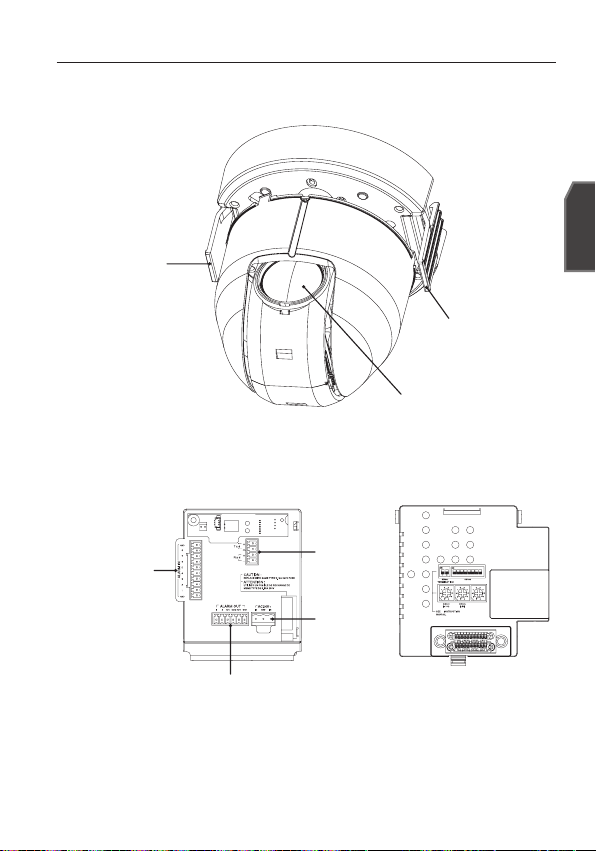
ОБЩИЙ ОБЗОР
КАМЕРА
ЗАЦЕП
РАМА ДЛЯ КРЕПЛЕНИЯ
Руский
ЗАЦЕП
ОБЪЕКТИВ
ALARM IN
RS-485
РАЗЪЕМ
ДЛЯ ШНУРА
ПИТАНИЯ
ALARM OUT
ЗАГРЯЗНЕННУЮ ПОВЕРХНОСТЬ ОБЪЕКТИВА ТРЕБУЕТСЯ ОСТОРОЖНО ПРОТЕРЕТЬ ТКАНЬЮ,
M
СМОЧЕННОЙ ЭТИЛОВЫМ СПИРТОМ.
ON
ON
1 2
12345678
SW604
(x 1)
Руский _7

установка и подключение
ПОДГОТОВКА К УСТАНОВКЕ
y
В случае самостоятельной установки камеры на потолке используйте
соответствующий шаблон.
y
Пропустите кабели через отверстие в форме
с клейкой подложки, а затем прикрепите шаблон в нужном месте на потолке.
y
В случае установки на раме, выровняйте все отверстия под винты на шаблонес
отверстиями на раме.
y
Данный шаблон препятствует попаданию пыли с потолка в блок камеры.
<ШАБЛОН>
КАБЕЛИПОТОЛОК КАБЕЛИПОТОЛОК ШАБЛОН
УСТАНОВКА
1.
Нажмите на “ЗАЩЕЛКИВАЮЩИЙСЯ РАЗЪЕМ”, который находится на
“АДАПТЕРЕ”, чтобы открыть “АДАПТЕР”. Пропустите кабели так, чтобы они
выходили из “РАМЫ ДЛЯ КРЕПЛЕНИЯ”.
РАМА ДЛЯ
КРЕПЛЕНИЯ
“”
РАМА ДЛЯ
КРЕПЛЕНИЯ
в центре шаблона и удалите пленки
АДАПТЕР
ЗАЩЕЛКИВАЮЩИЙСЯ
РАЗЪЕМ
8_ установка и подключение
АДАПТЕР
ВНЕШНИЕ
КАБЕЛИ
ЗАЩЕЛКИВАЮЩИЙСЯ
РАЗЪЕМ

Воспользуйтесь “ВИНТАМИ” для фиксации “РАМЫ ДЛЯ КРЕПЛЕНИЯ” на
2.
“КАМЕРЕ” в выбранном положении установки.
РАМА ДЛЯ
КРЕПЛЕНИЯ
ВИНТ
ВИНТ
АДАПТЕР
ВИНТ
<Схематичное Представление
Крепежных Отверстий>
Подсоедините внешние кабели к “РАЗЪЕМАМ (ALARM IN, ПИТАНИЯ, RS-485,
3.
ALARM OUT)” и подсоедините “РАЗЪЕМ” к “АДАПТЕРУ”.
Подсоедините кабель к “РАМЕ ДЛЯ КРЕПЛЕНИЯ” и закройте “АДАПТЕР”.
РАМА ДЛЯ
КРЕПЛЕНИЯ
РАЗЪЕМ ДЛЯ
ШНУРА ПИТАНИЯ
ALARM IN
Затем поместите “РАЗЪЕМ BNC” в “ИЗОЛЯЦИОННУЮ ТРУБКУ”. Воспользуйтесь
M
изоляционной лентой и заклейте край “ИЗОЛЯЦИОННОЙ ТРУБКИ” таким образом, чтобы
“РАЗЪЕМ BNC” не выступал за границы “ИЗОЛЯЦИОННОЙ ТРУБКИ”.
Более подробные сведения о подсоединении кабелей см. в разделе “Подключение
кабеля адаптера”. (стр. 17)
ALARM OUT
RS-485
АДАПТЕР
ЗАЩЕЛКИВАЮЩИЙСЯ РАЗЪЕМ
РАЗЪЕМ BNC
ИЗОЛЯЦИОННАЯ ТРУБКА
Руский _9
Руский
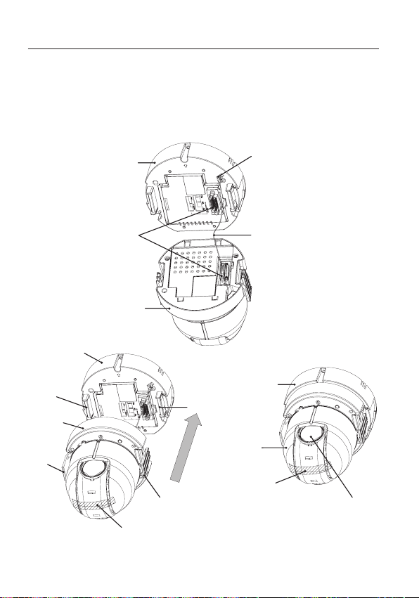
установка и подключение
4.
Подсоедините “КОНТРОВОЧНУЮ ПРОВОЛОКУ” “КАМЕРЫ” к “ПРОВОЛОЧНОЙ
СКОБЕ РАМЫ” для “КРЕПЛЕНИЯ”. Расположите “РАЗЪЕМ 22P” “КАМЕРЫ” на
одной линии с аналогичным разъемом “АДАПТЕРА”. Нажмите на “ЗАЦЕПЫ” с двух
сторон “КАМЕРЫ” в направлении “ДЕРЖАТЕЛЯ РАМЫ” для “КРЕПЛЕНИЯ”, чтобы
закрепить их. Убедитесь, что оба “ЗАЦЕПА” установлены до “щелчка” и закреплены
на “ДЕРЖАТЕЛЕ” соответствующим образом.
РАМА ДЛЯ
КРЕПЛЕНИЯ
РАЗЪЕМ 22P
КАМЕРА
РАМА ДЛЯ
КРЕПЛЕНИЯ
ДЕРЖАТЕЛЬ
КАМЕРА
ЗАЦЕП
ЗАЦЕП
ЗАЩИТНАЯ ЛЕНТА
После завершения установки удалите с объектива “ЗАЩИТНУЮ ПЛЕНКУ” и “ЗАЩИТНУЮ
M
ЛЕНТУ”.
10_ установка и подключение
ПРОВОЛОЧНАЯ СКОБА
КОНТРОВОЧНАЯ ПРОВОЛОКА
РАМА ДЛЯ
КРЕПЛЕНИЯ
ДЕРЖАТЕЛЬ
КАМЕРА
ЗАЩИТНАЯ ЛЕНТА
ЗАЩИТНАЯ ПЛЕНКА

Расположите на одной линии стрелку “КОЖУХА” и стрелку “РАМЫ ДЛЯ
5.
КРЕПЛЕНИЯ” и нажмите на “КОЖУХ”, чтобы зафиксировать его. Вставьте
“КОЖУХ” до упора и поверните его по часовой стрелке. Как показано на
рисунке ниже, кожух следует поворачивать, пока не появится отверстие для
“КНОПКИ” и не будет слышен щелчок.
Убедитесь, что “КОЖУХ” не переместится, если повернуть его против часовой стрелки.
РАМА ДЛЯ
КРЕПЛЕНИЯ
КАМЕРА
КОЖУХ
Если требуется снять “КОЖУХ”, удерживайте нажатой “КНОПКУ” и
поворачивайте “КОЖУХ” против часовой стрелки.
КОЖУХ
КНОПКА
КОЖУХ
КНОПКА
Руский
Руский _11

установка и подключение
ON
SW604
(x 1)
ON
1 2
12345678
ПЕРВОНАЧАЛЬНАЯ НАСТРОЙКА
Настройка адреса камеры
В качестве адреса камеры можно использовать значения SW606, SW605 и
SW604. Адрес можно указать в диапазоне от 0 до 255, где сотни задаются с
помощью SW606, десятки - с помощью SW605, а единицы - с помощью SW604.
Пример.) Адрес камеры: чтобы задать в качестве адреса 1, выполните действия,
представленные на рисунке ниже.
SW606
(x100)
SW605
(x10)
Настройка протокола связи
Протокол связи задается PIN-кодами #1~#4 SW603.
PIN
Comp
12_ установка и подключение
PIN1 PIN2 PIN3 PIN4
A OFF OFF OFF OFF
B ON OFF OFF OFF
C OFF ON OFF OFF
D ON ON OFF OFF
E OFF OFF ON OFF
F ON OFF ON OFF
G OFF ON ON OFF
H ON ON ON OFF
I OFF OFF OFF ON
J ON OFF OFF ON
K OFF ON OFF ON
L ON ON OFF ON
M OFF OFF ON ON
N ON OFF ON ON
O OFF ON ON ON
PONONONON
SW604
(x1)
А : SAMSUNG ПОЛУДУПЛЕКС
B : SAMSUNG ДУПЛЕКС
<Нижняя сторона держателя камеры>

Настройка скорости передачи в бодах
Скорость передачи в бодах настраивается с использованием PIN-кодов #5~#6 SW603.
Руский
CКOPOCTЬ(БOД) PIN 5 PIN 6
4800 BPS ON ON
9600 BPS OFF ON
19200 BPS ON OFF
38400 BPS OFF OFF
Заводская настройка по умолчанию для скорости в бодах - 9600 BPS.
Установка оконечной нагрузки линии связи RS-422A/RS-485
Как показано на структурной схеме, при использовании линии связи для передачи
сигналов на большие расстояния при подсоединении контроллера и линии
связи с интерфейсом RS-422А/RS-485, с обеих сторон линии связи должна быть
подключена оконечная нагрузка, величина которой зависит от импеданса кабеля.
Это необходимо для того, чтобы свести к минимуму отражение сигнала.
CAM n-1
n < 32
RX-
Оконечная нагрузка
SW1-ON
RX+
CAM n
Контроллер
Оконечная нагрузка
TX+(DATA+)
TX-(DATA-)
RX+ RX- RX+ RX- RX+ RX-
CAM 1
CAM 2
<Полудуплексная передача RS-485>
Оконечная нагрузка : установите переключатели 1 и 2 в положение <ВКЛ> и
оконечная нагрузка будет подключена.
Руский _13

установка и подключение
Контроллер
Оконечная
нагрузка
CAM 2CAM 1
<Организация дуплексной передачи по
стандарту RS-422А/RS-485>
Если подсоединить несколько видеокамер, которым в сети назначен одинаковый адрес,
M
могут возникать ошибки связи.
CAM n-1
n < 32
CAM n
Оконечная
нагрузка
SW1-ON
SW2-ON
14_ установка и подключение

ПОДКЛЮЧЕНИЕ К ДРУГОМУ УСТРОЙСТВУ
МОНИТОР
КОНТРОЛЛЕР/ЦИФРОВОЙ
ПОРТ ALARM IN
ВИДЕОМАГНИТОФОН
Руский
ПОРТ ALARM OUT
Подключение к монитору
Сначала подсоедините один
1.
конец кабеля с разъемами BNC
(миниатюрными байонетными
соединителями) к выходу
видеосигнала (VIDEO OUT)
видеокамеры.
2.
Затем подсоедините второй
конец этого кабеля к разъему
входа видеосигнала на
мониторе.
ИСТОЧНИК ПИТАНИЯ
Гнездо входа видеосигнала
на задней панели монитора
Кабель с разъемами BNC
Руский _15

установка и подключение
Подключение через порт ALARM IN
1.
Подсоедините один конец сигнального кабеля внешнего устройства к
соответствующему порту ALARM IN на мониторе.
2.
Другой конец сигнального кабеля подключите к порту заземления [GND].
Подключение через порт ALARM OUT
Подсоедините один конец сигнального кабеля внешнего устройства к
1.
соответствующему порту ALARM OUT на мониторе.
2.
Другой конец сигнального кабеля подключите к общему порту [COM].
Подключение контроллера
Подключите внешний контроллер или цифровой видеомагнитофон, с помощью
которого будет выполняться настройка камеры, к этой камере.
1.
Соедините контакт Rx+
камеры с контактом Tx+
контроллера.
2.
Соедините контакт Rxкамеры с контактом Txконтроллера.
3.
Соедините контакт Tx+
камеры с контактом Rx+
контроллера.
4.
Соедините контакт Txкамеры с контактом Rxконтроллера.
TxRx
16_ установка и подключение

Подсоединение кабеля адаптера
Плата адаптера
Руский
Источник питания
Подсоедините необходимые кабели и включите камеру, чтобы проверить,
правильно ли она работает.
1.
Подсоедините адаптер к разъему питания камеры.
2.
Подсоедините кабель питания адаптера к сетевой розетке.
Руский _17
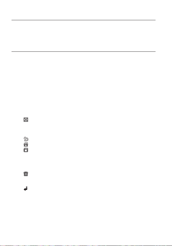
настройка
Подключите камеру к контроллеру клавиатуры или цифровому
видеомагнитофону, с помощью которого можно управлять камерой
и изменять ее настройки.
ИСПОЛЬЗОВАНИЕ КОНТРОЛЛЕРА КЛАВИАТУРЫ
Выполните указанные ниже действия, чтобы настроить меню камеры с помощью контроллера.
Откройте экран настройки камеры.
1.
Для перехода между различными меню используйте джойстик.
2.
Для выбора элемента меню нажмите [ENTER].
3.
Значение выбранного элемента меню можно изменить с помощью джойстика.
4.
Для применения внесенных изменений нажмите [ENTER].
5.
Использование экранных значков
y
◄►
:
Если эти значки отображаются в левом или правом углу элемента меню,
переход к предыдущему или следующему меню можно осуществлять с
помощью джойстика.
y
(ВЫХОД): выход из экрана настройки меню.
Перед выходом из экрана настройки выберите <СОХРАНИТЬ>,
чтобы сохранить настройки всех меню, или <ВЫХ.Б/СОХР>, чтобы
y
y
y
y
y
:
M
18_ настройка
отменить эти настройки.
(ВОЗВРАТ): сохранение настроек и возврат к предыдущему экрану.
(ИСХ.ПОЗ.): возврат к главному меню.
(COXPAHИTЬ): используйте этот значок, если необходимо сохранить
(УДАЛИТЬ): используйте этот значок, если необходимо удалить зону
этот значок отображается в правой части меню, содержащем элементы подменю.
Если камеру, работающую в режиме PRESET, AUTO PAN, SCAN или PATTERN
выключить, а затем снова включить без каких-либо определенных манипуляций, то
камера возобновит последний режим.
Настройка элемента меню возможна только в том случае, если значение угла наклона
находится в пределах 90.
Если войти в экран меню настройки, когда угол наклона камеры составляет более 90°,
камера повернется на 180° в симметричное положение с углом наклона менее 90°.
настройки после определения зоны маскирования, частной
зоны и т. д. Если настройки были один раз сохранены, они
уже не изменятся, даже если выход будет осуществлен с
помощью <BЫX.Б/COXP>.
маскирования, частную зону и т. д. Удаленные настройки не
восстановятся, даже если при выходе выбрать <BЫX.Б/COXP>.

ОСНОВНОЕ МЕНЮ
¾¾
OCHOBH OE MEHЮ
¾¾
HACTP. КAMEPЫ
C-MA OTCЛ EЖ-Я
ЧACTHAЯ ЗOHA
ПPEДУCT.
УCT. ABTO ПEPEMEЩEHИЯ
УCTAHOBКA ЗOH Ы
HACTPOЙ КA TPEBOГ
УCTAH. ЧACO B
ДP. HACTPOЙКИ
ИHФ. O CИCTEME
ЯЗЫК
Этот экран отображается первым при включении камеры. На нем задается необходимая
пользователю среда камеры.
Способ выбора и сохранения каждого из элементов меню описан в разделе “Использование
контроллера клавиатуры”. (стр. 18)
y
ПРОФИЛЬ
Выбор режима, соответствующего среде,
в которой устанавливается камера.
y
HACTP. КAMEPЫ
В этом меню можно выполнять настройку
камеры.
y
C-MA OTCЛEЖ-Я
Настройка функций обнаружения и
отслеживания движения объектов.
y
ЧACTHAЯ ЗOHA
В этом меню можно выполнять настройку
конфиденциальности.
y
ПPEДУCT.
В этом меню можно задать
ПРЕДУСТАНОВЛЕННОЕ ПОЛОЖЕНИЕ
камеры и выбрать значение параметра
ДЛИTEЛЬHOCTЬ.
y
УСТ. АВТО ПЕРЕМЕЩЕНИЯ
В этом меню содержатся элементы
подменю АВТО ПОВ, ШАБЛОН и СКАНИР..
y
УСТАНОВКА ЗОНЫ
В этом меню для камеры можно задать
стандартный угол ракурса и область зоны.
y
НАСТРОЙКА ТРЕВОГ
В этом меню можно задать приоритет сигналов тревоги и очередность
сигналов ввода-вывода.
y
УCTAH. ЧACOB
В этом меню можно задать время и его формат.
y
ДP. HACTPOЙКИ
В этом меню можно сбросить настройки камеры или выбрать другой цвет
экранных меню.
y
СВЯЗЬ
В этом меню выполняются настройки протокола связи RS-485.
y
ИHФ. O CИCTEME
В этом меню отображаются такие сведения о системе, как версия камеры
или настройки связи.
y
ЯЗЫК
Выбор предпочтительного языка из списка поддерживаемых языков.
¾¾
OCHOBHOE MEHЮ
ПPOФИЛЬ
HACTP. КAMEPЫ
C-MA OTCЛEЖ-Я
ЧACTHAЯ ЗOHA
ПPEДУCT.
УCT. ABTO ПEPEMEЩEHИЯ
УCTAHOBКA ЗOHЫ
HACTPOЙКA TPEBOГ
УCTAH. ЧACOB
ДP. HACTPOЙКИ
CBЯЗЬ
ИHФ. O CИCTEME
ЯЗЫК
¾¾
Руский _19
Руский

настройка
¾
CTAHДAPTHЫЙ
ITS
ФOHOB.C BET
ДEHЬ/HO ЧЬ
ИГPA
ПOЛЬ3OB
ПРОФИЛЬ
Можно выбрать одну из заранее определенных конфигураций, соответствующую
среде, в которой устанавливается камера.
Выбор того или иного элемента в меню ПРОФИЛЬ повлияет на все остальные
настройки камеры.
y
CTAHДAPTHЫЙ
При выборе этой настройки можно
Автоматическая оптимизация настроек
камеры в соответствии с обычной средой.
y
ITS
При выборе этой настройки можно
проанализировать рабочую нагрузку
камеры по соответствующим данным,
отображаемым на экране.
y
ФOHOB.CBET
При выборе этой настройки можно
различить объект на фоне даже в условиях недостаточной задней подсветки.
y
ДЕНЬ/НОЧЬ
Автоматическая оптимизация настроек камеры в соответствии с ночным или
дневным освещением.
y
ИГРА
Автоматическое выполнение настроек, обеспечивающее равномерное
освещение, сходное с освещением вне помещения.
y
ПОЛЬЗОВ
При переходе к любой из настроек меню ПРОФИЛЬ отобразится подменю ПОЛЬЗОВ.
МЕНЮ НАСТРОЕК КАМЕРЫ
Исходное Меню
VPS ВЫКЛ ВКЛ ВЫКЛ ВЫКЛ ВЫКЛ
ALC -----
ДИАФРАГМА
ФOHOB.CBET
WDR -----
УPOBEHЬ WDR
БАЛАНС БЕЛОГО
CTAHДAPTHЫЙ
Подменю
ALC ALC ALC ALC ALC
УРОВЕНЬ 00000
ВЫКЛ ВЫКЛ WDR ВЫКЛ ВЫКЛ
ВЕС
Настройка пользователя Настройка пользователя
Настройка пользователя Настройка пользователя 0Настройка пользователя Настройка пользователя
Настройка пользователя Настройка пользователя Настройка пользователя Настройка пользователя Настройка пользователя
ITS ФOHOB.CBET ДЕНЬ/НОЧЬ ИГРА
СРЕДНИЙ
W
¾
Настройка пользователя Настройка пользователя
ПPOФИЛЬ
CTAHДAPTHЫЙ
ITS
ФOHOB.CBET
ДEHЬ/HOЧЬ
ИГPA
ПOЛЬ3OB
X
20_ настройка

МЕНЮ НАСТРОЕК КАМЕРЫ
Исходное Меню
ДВИЖЕНИЕ
ЦШП СРЕДНИЙ СРЕДНИЙ СРЕДНИЙ СРЕДНИЙ СРЕДНИЙ
ЗАТВОР ВЫКЛ ВЫКЛ ВЫКЛ ВЫКЛ ВЫКЛ
HAKOПЛEHИE
XDR СРЕДНИЙ СРЕДНИЙ СРЕДНИЙ СРЕДНИЙ СРЕДНИЙ
ДЕНЬ/НОЧЬ
БАЛАНС
БЕЛОГО
ЧETКOCTЬ 22222
CTAHДAPTHЫЙ
Подменю
(OЧ.БЫCTP.)
---
ABTO X4 ABTO X2 ABTO X4 ABTO X4 ABTO X4
ABTO ABTO ДЕНЬ ABTO ДЕНЬ
НОЧЬ -----
ВСПЫШКА
ВНЕШНИЙ
ВСПЫШКА
ДЕНЬ -----
РЕЖИМ
КРАСНЫЙ
СИНИЙ
НОЧЬ -----
ЯPKOCTЬ
РЕЖИМ
КРАСНЫЙ
СИНИЙ
ВЫКЛ ВКЛ ВЫКЛ ВЫКЛ ВЫКЛ
-----
ВЫКЛ ВКЛ ВЫКЛ ВЫКЛ ВЫКЛ
ДЕНЬ ДЕНЬ/НОЧЬ ДЕНЬ ДЕНЬ/НОЧЬ ДЕНЬ
ATW2 ATW1 ATW1 ATW1 ATW1
00000
00000
Настройка пользователя
ВЫКЛ ATW2 ВЫКЛ ATW2 ВЫКЛ
Настройка пользователя 0Настройка пользователя 0Настройка пользователя
Настройка пользователя 0Настройка пользователя 0Настройка пользователя
ITS ФOHOB.CBET ДЕНЬ/НОЧЬ ИГРА
(OЧ.БЫCTP.)
---
СРЕДНИЙ
НОРМ.
Настройка пользователя
(OЧ.БЫCTP.)
---
СРЕДНИЙ
МЕДЛ.
Руский
Настройка пользователя
Руский _21

настройка
ID КAME PЫ BЫКЛ
VPS BЫКЛ
ДИAФPAГMA A LC
ДBИЖEHИ E (OЧ.БЫC TP.)
---
ЦШП CPEДN.
ЗATBOP (BЫКЛ )
--HAKOПЛE HИE ABTO X4
HEMEPЦA ЮЩEE BЫК Л
XDR CPEД N.
ID КA MEPЫ
BCD EFGHIJ KLMNO PQR STUVWX YZO
12 34 56 78 9
: ?
_
+
¾
()/
CДB
XX
WW
CДB MECTO
- - - - - - - - - - - - - - - - - - - - - - - - - - - - - - - -
- - - - - - - - - - - - - - - - - - - - - - - - - - - - - - - - -
HACTP. КAMEPЫ
You can configure the general settings of the camera module.
Способ выбора и сохранения каждого из элементов меню описан в разделе “Использование
контроллера клавиатуры”. (стр. 18)
Выберите <ОСНОВНОЕ МЕНЮ> -
1.
<HACTP. КAMEPЫ>.
Отобразится меню настройки камеры.
2.
Измените настройки по своему
усмотрению или выберите настройку,
которую требуется проверить.
ID КAMEPЫ
На экране отображается идентификационный номер и местоположение камеры.
Способ выбора и сохранения каждого из элементов меню описан в разделе “Использование
контроллера клавиатуры”. (стр. 18)
Выберите <HACTP. КAMEPЫ> -
1.
<ID КАМЕРЫ>.
2.
С помощью джойстика выберите нужные
символы, затем нажмите [ENTER].
Выбранный символ появится в нижнем
поле ввода экрана.
Возможен ввод до 54 символов, включая буквы,
цифры и специальные символы.
y
MECTO : задается место отображения
идентификационного номера камеры.
3.
После ввода номера нажмите [ENTER].
Идентификационный номер камеры отобразится в указанном месте.
VPS
Если для данной настройки выбрать значение <ВКЛ>, изображения, передаваемые
камерой, будут отображаться в режиме прогрессивной развертки.
W
HACTP. КAMEPЫ
ID КAMEPЫ BЫКЛ
VPS BЫКЛ
ДИAФPAГMA ALC
ДBИЖEHИE (OЧ.БЫCTP.)
ЦШП CPEДN.
ЗATBOP (BЫКЛ)
HAKOПЛEHИE ABTO X4
HEMEPЦAЮЩEE BЫКЛ
XDR CPEДN.
ID КAMEPЫ
A
BCDEFGHIJKLMNOPQRSTUVWXYZO
XX
WW
_
: ?
CДB MECTO
123456789
CДB
-
- - - - - - - - - - - - - - - - - - - - - - - - - - - - - - - -
- - - - - - - - - - - - - - - - - - - - - - - - - - - - - - - - -
X
¾
+
()/
---
---
22_ настройка

ДИАФРАГМА
ALC
ФOHOB.C BET BLC
OБЛACTЬ ПOЛЬЗOBAT.
<PAЗMEP>
<MECTO>
ALC
УPOBEHЬ
[
00
]
----
----
BEC CPEДN.
УPOBEHЬ WDR
[
0
]
----
----
БAЛAHC БEЛOГO BHУTPИ
PУЧHO Й
Меню ДИАФРАГМА используется, если
требуется отрегулировать интенсивность
излучения, поступающего в камеру.
y
ALC : регулировка открытия или
закрытия диафрагмы.
- УРОВЕНЬ : выберите общий уровень яркости.
УPOBEHЬ
ФOHOB.CBET BLC
OБЛACTЬ ПOЛЬЗOBAT.
<PAЗMEP>
<MECTO>
- BLC : если для параметра <ФOHOB.
CBET> выбрать значение <BLC>,
можно задать область BLC.
Если для параметра ОБЛАСТЬ выбрать
значение <ПOЛЬЗOBAT.>, можно задать положение и размер.
- WDR : если для параметра <ФОНОВ.
СВЕТ> выбрать значение <WDR>,
отобразится меню, в котором можно
задать параметры WDR.
В меню УРОВЕНЬ WDR задайте скорость
срабатывания затвора, а в меню <BEC> уровень композиции.
УPOBEHЬ
ФOHOB.CBET WDR
BEC CPEДN.
УPOBEHЬ WDR
БAЛAHC БEЛOГO BHУTPИ
В меню <БАЛАНС БЕЛОГО> выберите
УЛИЧНАЯ или ВНУТРИ.
Функция WDR позволяет расширить
диапазон усиления. Она особенно
полезна, если съемки производятся как в помещении, так и на улице.
Благодаря этой функции повышается четкость изображения в сценах,
снимаемых как на улице, так и в помещении.
Если используется функция VPS, функция WDR недоступна, поскольку метод считывания
M
CCD обладает существенными отличиями. Если для параметра VPS установить значение
ВКЛ, то для параметра WDR будет установлено значение <ВЫКЛ>.
y
РУЧНОЙ : настройка уровня диафрагмы
вручную.
Для значения общей яркости будет задан
M
нулевой уровень параметра ALC, а
УPOBEHЬ
диафрагма может быть настроена вручную.
ALC
ALC
PУЧHOЙ
[
00]
[
[
[ 00]
00
----I----
]
----II
]
0
----II
----I----
----
----
Руский
Руский _23

настройка
W
HACTP. КAMEPЫ
X
ID КAME PЫ BЫКЛ
VPS
BЫКЛ
ДИAФPAГMA A LC
ЦШП CPEДN.
ЗATBOP
BЫКЛ
HAKOПЛE HИE
BЫКЛ
HEMEPЦA ЮЩEE
BЫКЛ
XDR CPEД N.
АРУ
Выбрав этот элемент меню, можно
настроить для камеры уровень АРУ.
Если при выбранном параметре АРУ
мощность сигнала ниже стандартного
уровня, параметр АРУ усилит видеосигнал и
автоматически оптимизирует уровень
чувствительности.
Если для параметра <НАКОПЛЕНИЕ>
выбрано значение <ВЫКЛ> или <ФИКС.>,
меню <ДВИЖЕНИЕ> изменится на <АРУ>.
ыбрав подменю ПОЛЬЗОВАТ.
( )
, нажмите
[ENTER], чтобы отобразился
соответствующий экран. В этом режиме можно выбрать один из 16 уровней: от
ОЧЕНЬ НИЗКИЙ до ОЧЕНЬ ВЫСОК и расширить выбор параметров.
Выбрав подменю ФИКС.
соответствующий экран. В данном режиме можно выбрать свой режим для
()
, нажмите [ENTER], чтобы отобразился
каждого из 16 уровней, независимо от заданного уровня яркости.
Если на экране настройки камеры в меню ДЕНЬ/НОЧЬ задано значение АВТО, меню АРУ
M
будет недоступно.
Если для параметра HEMEPЦAЮЩEE выбрать значение ВКЛ, режим АРУ будет недоступен.
Если для параметра ФОНОВ.СВЕТ выбрать значение WDR, режим фиксации APУ ФИKC.
будет недоступен.
ДВИЖЕНИЕ
Можно задать уровень АРУ и с его помощью управлять движением камеры.
Эта настройка возможна, только если в меню НАКОПЛЕНИЕ выбрано значение
АВТО. Выберите значение OЧ.БЫCTP., если требуется отслеживание очень
быстро передвигающегося объекта в условиях малой контрастности, и
значение ОЧ.МЕДЛ., если в таких же условиях отслеживается объект, который
перемещается очень медленно.
Если для параметра ДЕНЬ/НОЧЬ задано значение <АВТО>, меню <ДВИЖЕНИЕ> будет недоступно.
W
HACTP. КAMEPЫ
ID КAMEPЫ BЫКЛ
VPS
ДИAФPAГMA ALC
APУ (OЧEHЬ BЫCOK)
ЦШП CPEДN.
ЗATBOP
HAKOПЛEHИE
HEMEPЦAЮЩEE
XDR CPEДN.
X
BЫКЛ
---
BЫКЛ
BЫКЛ
BЫКЛ
ЦШП
Снижение уровня шума на изображении, передаваемом камерой.
Чем выше выбран уровень, тем сильнее эффект.
Чтобы задать уровень, выберите <ПОЛЬЗОВАТ.>.
24_ настройка

ЗАТВОР
W
HACTP. КAMEPЫ
X
ID КAME PЫ BЫКЛ
VPS
BЫКЛ
ДИAФPAГMA A LC
APУ (OЧEHЬ BЫCOK)
---
ЦШП CPEДN.
HAKOПЛE HИE (
BЫКЛ
---
HEMEPЦA ЮЩEE (
BЫКЛ
---
XDR CPEД N.
Можно выбрать одно из 7 значений
фиксированной скорости срабатывания
электронного затвора: от 1/120 до 1/10k.
Последнее значение используется главным
образом при съемке очень быстро
перемещающегося объекта.
Если для параметра HAKOПЛEHИE задать значение
АВТО, для параметра ФИКС./НЕМЕРЦАЮЩЕЕ значение ВКЛ, для параметра ФOHOB.CBET значение WDR, то меню ЗАТВОР будет недоступно.
W
HACTP. КAMEPЫ
ID КAMEPЫ BЫКЛ
VPS
ДИAФPAГMA ALC
APУ (OЧEHЬ BЫCOK)
ЦШП CPEДN.
ЗATBOP 1/120
HAKOПЛEHИE (
HEMEPЦAЮЩEE (
XDR CPEДN.
X
BЫКЛ) )
BЫКЛ) )
BЫКЛ
---
---
---
HAKOПЛEHИE
Автоматическое определение уровня затемнения в ночное время или в
условиях с низкой контрастностью и увеличение времени накопления в
соответствии с этим определенным уровнем. Для ярких и четких изображений
можно выбрать значение <АВТО> или <ФИКС.>.
Если в меню ЗАТВОР установлен режим фиксированного электронного затвора, меню
M
НАКОПЛЕНИЕ будет недоступно.
Если для параметра НЕМЕРЦАЮЩЕЕ задать значение ВКЛ или для параметра ФOHOB.
CBET задать значение WDR, режим ФИКС. в меню HAKOПЛEHИE будет недоступен.
НЕМЕРЦАЮЩЕЕ
Выбор этого параметра поможет предотвратить возможное искажение на
экране вследствие несоответствия частоты покадровой синхронизации и
частоты мерцания света. Если для этого параметра выбрать значение <ВКЛ>,
будет задана фиксированная скорость срабатывания затвора: 1/120 секунды.
Если для параметров ЗАТВОР, HAKOПЛEHИE и АРУ задать значение ФИКС., то меню
<НЕМЕРЦАЮЩЕЕ> будет недоступно.
XDR
При выборе этого параметра корректируется различие уровней яркости
в различных сценах. Это позволяет добиться оптимальной видимости,
поскольку выполняется расчет контрастности при окружающем освещении для
определенного числа пикселей.
Чем выше значение, тем точнее корректировка.
Руский
Руский _25

настройка
3OHA MA CKИP.
<MECTO>
БAЛAHC БEЛOГO
PEЖИM Ф OКУC. OДHOКP. AФ
CКOP. TPAHCФOК. [
2
]
ИHД.ЗУMA BЫКЛ
ИHД.ПOB /HAKЛ BЫ КЛ
ЦИФP УBE ЛИЧEHИE BЫКЛ
ЧETКOCT Ь [
2
]
КAДP CИH XP. BHУ TP
ABTO
ДEHЬ
¨
HOЧЬ
ЯPKOCTЬ CPEДN.
BЫДEPЖКA BPEM.
2S
HOЧЬ
¨
ДEHЬ
ЯPKOCTЬ CPEДN.
BЫДEPЖКA BPEM.
5S
3OHA MACK ИP.
1 2
ДЕНЬ/НОЧЬ
Можно задать необходимый режим записи в соответствии с условиями съемки.
Способ выбора и сохранения каждого из элементов меню описан в разделе “Использование
контроллера клавиатуры”. (стр. 18)
Выберите <HACTP. КAMEPЫ> -
1.
<ДEНЬ/НOЧЬ>.
2.
В соответствии с освещением выберите
переходный режим экрана и задайте
соответствующие параметры.
y
ДЕНЬ : установка режима ДЕНЬ,
независимо от освещения.
y
НОЧЬ : установка режима НОЧЬ,
независимо от освещения. Если для
параметра ВСПЫШКА установлено
значение <ВКЛ>, сигнал вспышки
будет выводиться вместе с чернобелым композитным видеосигналом.
y
АВТО : переключение режимов ДЕНЬ/
НОЧЬ происходит в соответствии с
освещением.
ВСПЫШКА : если для данного
-
параметра установлено значение
<ВЫКЛ>, сигнал вспышки выводиться
в режиме НОЧЬ не будет.
HOЧЬ ЯРКОСТЬ : настройка
-
ДEHЬ
¨
изменения уровня яркости при
переключении с фильтра ЦВЕТНОЕ
на фильтр Ч-Б. При переключении
со значения ВЫСОКИЙ на значение
НИЗКИЙ переключение фильтра
выполняется в условиях меньшей освещенности.
ДEHЬ¨HOЧЬ BЫДEPЖКA BPEM. : время, требуемое для определения
-
переключения фильтра.
HOЧЬ¨ДEHЬ ЯРКОСТЬ : настройка изменения уровня яркости при
-
переключении с фильтра Ч-Б на фильтр ЦВЕТНОЕ. При переключении
со значения ВЫСОКИЙ на значение НИЗКИЙ переключение фильтра
выполняется в условиях меньшей освещенности.
-
HOЧЬ¨ДEHЬ BЫДEPЖКA BPEM. : время, требуемое для определения
переключения фильтра.
3OHA МАСКИР. : при наличии ярких
-
точечных источников света в ночное
время можно задать необходимый
размер и положение. Это позволяет
предотвратить ошибку переключения
фильтра или невозможность
определить необходимость
переключения при наличии ярких
точечных источников света ночью.
Все чрезмерно яркие зоны в ночное
время будут замаскированы.
26_ настройка
ДEHЬ/HOЧЬ ABTO
БAЛAHC БEЛO ГO
PEЖИM ФOКУC. OДHOКP. AФ
CКOP. TPAHCФOК. [
ИHД.ЗУMA BЫКЛ
ИHД.ПOB/HAKЛ BЫКЛ
ЦИФP УBEЛИЧEHИE BЫКЛ
ЧETКOCTЬ [
КAДP CИHXP. BHУTP
ABTO
BCПЫШКA BЫКЛ
¨
ДEHЬ
HOЧЬ
ЯPKOCTЬ CPEДN.
BЫДEPЖКA BPEM.
¨
HOЧЬ
ДEHЬ
ЯPKOCTЬ CPEДN.
BЫДEPЖКA BPEM.
3OHA MACKИP.
3OHA MACKИP.
<PAЗMEP>
<MECTO>
2
]
]
2
2S
5S
1 2

Можно указать зону МАСКИР. 1 и 2 одновременно.
Если для параметра <ФОНОВ.СВЕТ> установлено значение <BLC>, функция ЗОНА МАСКИР.
будет отключена.
y
ВНЕШНИЙ : при подключении внешнего датчика возможно автоматическое
переключение режимов ДЕНЬ и НОЧЬ. Если для параметра <ДЕНЬ/НОЧЬ>
установлено значение ВНЕШНИЙ, а для параметра датчика #1 НАСТРОЙКА ТРЕВОГ
- УCT. BXOДA TPEB - значение NO/NC, данный датчик можно использовать для
передачи входного сигнала в режиме ВНЕШНИЙ параметра <ДЕНЬ/НОЧЬ>. При
передаче с датчика сигнала тревоги данный режим изменится на НОЧЬ.
Если для параметра <ДЕНЬ/НОЧЬ> установлено значение ВНЕШНИЙ, то значение ТРЕВОГА1
M
не доступно для параметров УCT.BЫX.TPEBOГИ и HACTPOЙКA TPEBOГ - УСТ. АВТО.
Если используется инфракрасный источник света в режиме АВТО, возможны ошибки при
выполнении операций АВТОПЕРЕКЛЮЧЕНИЕ или АВТОФОКУСИРОВКА.
БАЛАНС БЕЛОГО
Для настройки цвета в соответствии с внешним освещением можно использовать
функцию <БАЛАНС БЕЛОГО>.
Способ выбора и сохранения каждого из элементов меню описан в разделе “Использование
контроллера клавиатуры”. (стр. 18)
Освещение обычно называют цветовой температурой, которая измеряется в
Кельвинах (К). Для обычных источников освещения классификация цветовой
температуры выглядит следующим образом.
В меню <БАЛАНС БЕЛОГО> можно
задать режим, для корректировки
параметра <БАЛАНС БЕЛОГО>.
- ATW1,2 : если в меню <БАЛАНС
БЕЛОГО> установлен режим
<ATW1> или <ATW2> ,
отслеживаются изменения
цветовой температуры, в
соответствии с которыми
выполняется корректировка
параметра <БАЛАНС БЕЛОГО>.
Для каждого режима задан свой
диапазон цветовых температур:
ATW1 : 2500K ~ 9300K (Ú1)
ATW2 : 2000K ~ 10000K
(подходит для натриевых ламп) (Ú2)
1 :
Если установлен режим <ATW1> , когда цветовая температура
Ú
окружающей среды находится за пределами диапазона 2500 К - 9300 К, то
не всегда можно подобрать соответствующее значение баланса белого. В
таком случае рекомендуется установить режим <ATW2>
2 :
Если установлен режим <ATW2> , когда цветовая температура окружающей
Ú
среды почти всегда постоянна, отображаемый и фактический цвет могут
отличаться. Таким образом, необходимо выбрать режим, соответствующий
данной цветовой температуре окружающей среды.
10000K
9000K
8000K
7000K
6000K
5000K
4000K
3000K
2000K
1000K
Голубое небо
Дождливая
погода
Облачность
Переменная
Солнечная погода
Люминесцентная лампа
Люминесцентная
Свеча
Вольфрамовая лампа
облачность
лампа
накаливания
Руский _27
Руский

настройка
БAЛAH C БEЛOГ O
ДEHЬ/HO ЧЬ HOЧЬ
ЯPKOCTЬ CPEДN.
КPACHЫЙ
[
00
]
----
I
----
CИHИЙ
[
00
]
----
I
----
УCИЛEHИ E R
[
0064
]
УCИЛEHИ E B
[
0064
]
БAЛAH C БEЛOГ O
ДEHЬ/HO ЧЬ ДEHЬ
КPACHЫЙ
[
00
]
----
I
----
CИHИЙ
[
00
]
----
I
----
УCИЛEHИ E R
[
0064
]
УCИЛEHИ E B
[
0064
]
Выберите <HACTP. КAMEPЫ> - <БАЛАНС БЕЛОГО>.
1.
Выберите режим, для которого задается значение параметра <БАЛАНС БЕЛОГО>.
2.
y
ДЕНЬ : в режиме ДЕНЬ можно задать
значения КРАСНЫЙ и СИНИЙ.
Экран будет отображаться
в соответствии с заданными
настройками цвета.
Значения параметров УСИЛЕНИЕ R и УСИЛЕНИЕ В
можно установить только в режиме <AWC>.
Если для параметра АРУ установлено значение
<ВЫКЛ> или <ФИКС.>, невозможно получить
доступ к меню НОЧЬ.
y
НОЧЬ : параметр <БАЛАНС БЕЛОГО>
можно настроить в соответствии с
внешним освещением.
Если для режима НОЧЬ установлено
значение <ВЫКЛ>, функция <БАЛАНС
БЕЛОГО> будет всегда работать с
настройками, заданными в режиме
ДЕНЬ. Если будет установлено другое
значение, экран перейдет в режим,
заданный в режиме <ДЕНЬ/НОЧЬ>.
В режиме ДЕНЬ можно установить
значения КРАСНЫЙ, СИНИЙ и
ЯРКОСТЬ. Экран будет отображаться в
соответствии с заданными настройками цвета.
Исходя из заданного режима записи, выберите режим <БАЛАНС БЕЛОГО> и
3.
необходимые параметры.
y
ATW1, 2 : Камера может автоматически регулировать цветовую
температуру в реальном времени в соответствии с внешними условиями.
(Диапазон цветовых температур 1: 2500 K - 9300 K; 2: 2000 K - 10000 K)
y
AWC : при нажатии [ENTER] на интересующем элементе будет включен
режим ATW.
Можно установить значения параметров УСИЛЕНИЕ R/УСИЛЕНИЕ В.
y
3200K : установка цветовой температуры 3200 K.
y
5600K : установка цветовой температуры 5600 K.
ЯРКОСТЬ : установка изменения уровня яркости при переходе из
-
режима ДЕНЬ в режим НОЧЬ.
КРАСНЫЙ : настройка глубины красного цвета.
-
Синий : настройка глубины синего цвета.
-
УСИЛЕНИЕ R/УСИЛЕНИЕ В : установка текущей цветовой температуры
-
вручную.
БAЛAHC БEЛO ГO
ДEHЬ/HOЧЬ ДEHЬ
PEЖИM AWC
КPACHЫЙ
CИHИЙ
ДEHЬ/HOЧЬ HOЧЬ
ЯPKOCTЬ CPEДN.
PEЖИM AWC
КPACHЫЙ
CИHИЙ
УCИЛEHИE R
УCИЛEHИE B
БAЛAHC БEЛO ГO
УCИЛEHИE R
УCИЛEHИE B
[
[
[
[
[
[
0064
0064
[
[
0064
0064
----
----
]
I
00
----
----
]
I
00
]
]
----
----
]
I
00
----
----
]
I
00
]
]
28_ настройка

РЕЖИМ ФОКУС.
ДEHЬ/HO ЧЬ ABTO
БAЛAHC БEЛOГO
CКOP. TPAHCФOК.
[
2
]
ИHД.ЗУMA BЫКЛ
ИHД.ПOB /HAKЛ BЫ КЛ
ЦИФP УBE ЛИЧEHИE X16
ЧETКOCT Ь [
2
]
КAДP CИH XP. BHУ TP
Режим фокусировки можно выбрать, исходя
из заданного для камеры угла съемки.
- АФ : непрерывное отслеживание
изображения для автоматической
фокусировки. Если в данном режиме
выполнить настройку фокусировки
вручную, то далее она будет
осуществляться так же, как и в режиме
<РФ>. В данном режиме фокусировка
сохраняется после каждой операции
панорамирования/наклона/трансфокации.
OДHOКP. AФ : фокусировка сохраняется
-
после каждой операции панорамирования/наклона/трансфокации. Камера
работает так же, как в режиме <РФ>, пока не выполняется операция
панорамирования/наклона/трансфокации.
ДEHЬ/HOЧЬ ABTO
БAЛAHC БEЛO ГO
PEЖИM ФOКУC. OДHOКP. AФ
CКOP. TPAHCФOК.
ИHД.ЗУMA BЫКЛ
ИHД.ПOB/HAKЛ BЫКЛ
ЦИФP УBEЛИЧEHИE X16
ЧETКOCTЬ [
КAДP CИHXP. BHУTP
[
]
2
]
2
- РФ : настройка фокусировки выполняется вручную.
Устройство может работать неисправно в режиме <АФ> при наблюдении за
M
перечисленными ниже объектами. В этом случае используйте режим <РФ>.
- Очень яркий объект или доминирующий объект на темном фоне
- Объекты, снимаемые через мокрое или грязное стекло
- Съемка комбинации близлежащих и удаленных объектов
- Белая стена или одноцветный объект
- Жалюзи и другие объекты с горизонтальными полосами
CКOP. TPAHCФOК.
Можно настроить скорость трансфокации.
ИHД.ЗУMA
Можно включить отображение состояния трансфокации на экране.
Оно исчезнет через 3 секунды, если больше не будет изменяться коэффициент масштаба.
ИHД.ПOB/HAKЛ
Можно задать отображение состояния действия панорамирования/наклона,
если оно включено.
Оно исчезнет через 3 секунды, если больше не будет изменяться положение перемещение и
наклона. Однако допустимая ошибка составляет ±2°.
ЦИФP УBEЛИЧEHИE
Можно задать коэффициент максимального цифрового увеличения.
Функция цифрового увеличения срабатывает, когда оптическое увеличение
достигает своего максимального значения - x25.
Если для параметра ЦИФP УBEЛИЧEHИE установить значение x16, то можно
осуществлять съемку с коэффициентом увеличения до x400 (43x16).
ЧETКOCTЬ
Используется для регулировки разрешающей способности по вертикали и
горизонтали.
Руский _29
Руский

настройка
ИHBEPTИ P. BЫКЛ
ПOЗ/HEГ ATИB +
PIP BЫКЛ
DIS BЫКЛ
КAДP CИHXP.
Можно задать режим для параметра КAДP CИHXP..
- Если установлен режим <ВНУТР>, в камере будет использоваться внутренняя
синхронизация.
- Если установлен режим <ЛИНИЯ>, то для синхронизации в камере будет
использоваться частота внешнего источника питания.
Для параметра ФАЗА СИНХ. СЕТИ можно задать соответствующие настройки.
APУ ЦBETA
Можно настроить диапазон цветопередачи
в соответствии с параметром АРУ.
ИНВЕНТИР.
Можно инвертировать видеосигнал слева
направо, снизу вверх или наоборот по
своему усмотрению.
ПОЗ/НЕГАТИВ
Можно установить для сигнала яркости
видео обычное значение или значение негатива.
PIP
Одновременный просмотр основного и дополнительного изображения на экране.
Если указано несколько значений параметра ЧАСТНАЯ ЗОНА и для параметра УСТ.ЧАСТ.3ОНЫ
M
установлено значение <ВКЛ>, функция PIP будет отключена.
Пока для параметра УВ ЧУВС установлено значение ФИКС, меню PIP недоступно.
В соответствии со степенью освещенности PIP не будет отображаться, если значение в меню
УВ ЧУВС выбрано значение АВТО.
DIS (Цифровая стабилизация изображения)
Если для данного параметра установлено значение <ВКЛ>, мерцание на экране
автоматически компенсируется, когда из-за внешнего воздействия камера
трясется или вибрирует.
Если для параметра<DIS> установлено значение <ВКЛ>, с помощью функции цифрового
M
увеличения изображение можно увеличивать в пределах зоны компенсации. (Приблизительно 1,2
раза от значения оптического зума)
Если установить коэффициент цифрового увеличения больше коэффициента увеличения зоны
компенсации, функция <DIS> будет отключена.
Функция <DIS> может работать неправильно при отображении следующих изображений.
Оодноцветное плоское изображение / Съемка в условиях низкой контрастности / Высокочастотное
изображение, снятое при освещении люминесцентной лампой / Изображение с повторяющимся рисунком
30_ настройка
APУ ЦBETA CPEДN.
ИHBEPTИP. B ЫКЛ
ПOЗ/HEГAT ИB +
PIP BЫКЛ
DIS BЫКЛ

ИНТЕЛЛЕКТУАЛЬНОЕ ВИДЕО
ДBИЖEHИ E B ЫКЛ
УЛУЧWEHHЫ Й BЫКЛ
3OHA MACK ИP.
1 2 3 4
ДИCПЛEЙ BКЛ
ЧУBCTBИ T.
[
4
]
PA3PEWEHNE
[
3
]
BЫXOД T PEBOГИ
3OHA MA CKИP.
<MECTO>
Возможность включения функций обнаружения и отслеживания движения объекта.
Способ выбора и сохранения каждого из элементов меню описан в разделе “Использование
контроллера клавиатуры”. (стр. 18)
Выберите <ОСНОВНОЕ МЕНЮ> -
1.
<C-МА ОТСЛЕЖ-Я>.
Выберите и задайте соответствующие
2.
настройки для каждого параметра.
ДВИЖЕНИЕ
Возможность включения функций обнаружения
и отслеживания движения объекта.
Если для параметра <ОПРЕДЕЛ> установлено
значение <ФИКС/ДВИЖ>, параметры меню
M
УЛУЧШЕННЫЙ будут недоступны.
Функции обнаружения и отслеживания движения объекта могут работать неисправно в
следующих условиях.
- При внезапном изменении яркости
- При перемещении устройства
- Когда основной перемещающийся объект занимает основную часть кадра
- Когда трудно выделить движущийся объект из фона
УЛУЧШЕННЫЙ
При обнаружении движения можно отметить фрагмент видео, в котором
содержится данное движение, что позволяет отслеживать перемещение объекта.
(Функция авто PTZ не поддерживается для отслеживания объекта.)
При выборе параметра <ФИKC/ДBИЖ> отмечается область, в случае если
существующий объект исчезнет с экрана, или появится новый объект, который
фиксируется в течение некоторого времени.
Обнаружение с помощью параметра ФИКС/ДВИЖ может работать неисправно при следующих условиях.
M
- Непрерывное перемещение нескольких объектов в произвольных направлениях.
- Зафиксированный объект непрерывно перемещается в одном направлении.
- Новый появившийся объект закрывает первый движущийся объект.
3OНA МАСКИР.
Укажите номер зоны для выполнения
1.
маскировки, в которой исключается
возможность обнаружения движения.
Выберите номер маски и укажите ее
2.
размер и зону покрытия.
W
C-MA OTCЛEЖ-Я
ДBИЖEHИE BЫКЛ
УЛУЧWEHHЫЙ BЫКЛ
3OHA MACKИP.
ДИCПЛEЙ BКЛ
[
ЧУBCTBИT.
PA3PEWEHNE
BЫXOД TPEBOГИ
<PAЗMEP>
<MECTO>
[
3OHA MACKИP.
X
1 2 3 4
]
4
]
3
Руский
Руский _31

настройка
1 2 3 4 5 6
7 8 9 10 11 12
УCT.ЧACT.3OHЫ
BКЛ
CTИЛЬ
MOЗAИКA 1
BЫXOД TPEBOГ И
ФИKC/ДB ИЖ B КЛ
ДИСПЛЕЙ
Если для данного параметра установлено значение <ВКЛ>, на экране
отображается обнаруженное движение или событие в соответствии с
настройками расширенной функции.
ЧУВСТВИТЕЛЬН.
Установка чувствительности датчика движения.
РАЗРЕШЕНИЕ
Более высокое разрешение позволяет обнаружить более мелкие объекты.
BЫXOД TPEBOГИ
Если для данного параметра установлено
значение <ВКЛ>, подается сигнал тревоги
при обнаружении движения или события в
BЫXOД TPEBOГИ
ДBИЖEHИE BКЛ
ФИKC/ДBИЖ BКЛ
соответствии с настройками расширенной
функции.
ЧACTHAЯ ЗOHA
Можно задать до 12 частных зон, которые будут скрыты при записи для защиты
конфиденциальности объекта.
Настройка частной зоны
Способ выбора и сохранения каждого из элементов меню описан в разделе “Использование
контроллера клавиатуры”. (стр. 18)
Выберите <ОСНОВНОЕ МЕНЮ> -
1.
<ЧАСТНАЯ ЗОНА>.
2.
Укажите номер зоны и нажмите [ENTER].
Появится экран настройки.
3.
3. Выберите <УСТАН.П/H/Ф> и нажмите
[ENTER].
С помощью джойстика выполните
настройки панорамирования, наклона и
трансфокации.
32_ настройка
W
ЧACTHAЯ ЗOHA
1 2 3 4 5 6
7 8 9 10 11 12
УCT.ЧACT.3OHЫ
CTИЛЬ
X
MOЗAИКA1
BКЛ

Выберите <УРОВЕНЬ ПИКС.>.
ЧACTH AЯ ЗOHA S ET 1
УPOBEHЬ ПИKC. [
4
]
<PAЗMEP>
<MECTO>
¾¾
OCHOBH OE MEHЮ
¾¾
ПPOФИЛЬ
HACTP. КAMEPЫ
C-MA OTCЛ EЖ-Я
ЧACTHAЯ ЗOHA
УCT. ABTO ПEPEMEЩEHИЯ
УCTAHOBКA ЗOH Ы
HACTPOЙ КA TPEBOГ
УCTAH. ЧACO B
ДP. HACTPOЙКИ
4.
Задайте уровень пикселей для
параметров РАЗМЕР и MECTO.
5.
Выберите <РАЗМЕР> и нажмите [ENTER].
С помощью джойстика установите размер
частной зоны.
6.
Выберите <MECTO> и нажмите [ENTER].
ЧACTHAЯ ЗOHA SET 1
<УCTAH.П/H/Ф>
УPOBEHЬ ПИKC. [
<PAЗMEP>
<MECTO>
]
4
С помощью джойстика установите
расположение частной зоны.
7.
Сохраните внесенные изменения и
перейдите к предыдущему экрану, затем
выберите <СТИЛЬ>
Выберите <ЦВЕТНОЕ> и выберите нужный цвет.
При установке одной или нескольких частных зон и включении функции
M
конфиденциальности функция PIP будет отключена.
Для более надежной конфиденциальности можно увеличить рекомендуемый размер
частной зоны до 30%.
Область видео, скрытого мозаичным изображением или закрашенного в соответствии с
настройками частной зоны не поддается восстановлению.
ПPEДУCT.
С помощью данной функции можно задать запрограммированные настройки
камеры, такие как панорамирование, наклон, трансфокация и фокусировка, для
более быстрого и легкого использования устройства и осуществления контроля. Эта
функция поддерживает до 512 предустановок.
Способ выбора и сохранения каждого из элементов меню описан в разделе “Использование
контроллера клавиатуры”. (стр. 18)
Выберите <ОСНОВНОЕ МЕНЮ> -
1.
<ПРЕДУСТ.>.
¾¾
OCHOBHOE MEHЮ
ПPOФИЛЬ
HACTP. КAMEPЫ
C-MA OTCЛEЖ-Я
ЧACTHAЯ ЗOHA
ПPEДУCT.
УCT. ABTO ПEPEMEЩEHИЯ
УCTAHOBКA ЗOHЫ
HACTPOЙКA TPEBOГ
УCTAH. ЧACOB
ДP. HACTPOЙКИ
¾¾
Руский
Руский _33

настройка
0
¾
1 2 3 4
5 6 7 8 9
10 11 12 13 14
15 16 17 18 19
20 21 22 23 24
25 26 27 28 29
30 31
W
1/16
X
ПPEДУ CTAHOBКA № 1
ID ПPEД УCT. BКЛ
ПPEДУCT. CКOP. [
5
]
BЫДEPЖК A BPEM. 3S
УДEPЖ. ИЗO БP. BЫКЛ
HACTP. КAMEPЫ BКЛ
HACTP. КAMEP Ы
БAЛAHC БEЛOГO
PEЖИM Ф OКУC. PФ
Выберите номер предварительной
2.
установки.
3.
Выберите <ПОЗИЦИЯ> и с помощью
джойстика задайте необходимые настройки
для параметра <ПАНОРАМИРОВАНИЕ/
НАКЛОН/ТРАНСФ>.
4.
Для параметра <ID ПРЕДУСТ.> установите
значение <ВКЛ>и введите имя.
Для получения информации о процедуре ввода
имени см. пункт “ID КАМЕРЫ”. (стр. 22)
Выберите <ПРЕДУСТ. СКОР.> и
5.
измените скорость предустановленных
значений панорамирования/наклона.
Задайте значение для параметра
6.
<ВЫДЕРЖКА ВРЕМ.>, определяющее продолжительность выдержки
камеры, и предустановленное значение для параметра <УДЕРЖ. ИЗОБР.>.
Если для параметра <УДЕРЖ. ИЗОБР.> установлено значение <ВКЛ>, видео изображение
будет оставаться неподвижным, пока камера не займет предустановленного положения.
Установите для параметра <НАСТР.
7.
КАМЕРЫ> значение <ВКЛ>.
Для каждой предустановки можно задать
настройки камеры.
Информацию по установке значений для параметров
<ДИАФРАГМА>, <БАЛАНС БЕЛОГО> и
<РЕЖИМ ФОКУС.> см. пункт “НАСТР. КАМЕРЫ”.
(стр. 22 - 30)
Если в основном меню в настройках камеры
M
для параметра VPS установлено значение
ВКЛ, камера будет работать в данном режиме
VPS, даже если в меню ПРЕДУСТ. будет включен параметр WDR.
Если в меню ПРЕДУСТ. используется параметр WDR, камера будет работать в данном
режиме и сбросит все предыдущие настройки, даже если в основном меню для параметров
АРУ и НАКОПЛЕНИЕ установлено значение ФИКС., а для параметра ЗАТВОР - значение ВКЛ.
34_ настройка
W
0
5 6 7 8 9
10 11 12 13 14
15 16 17 18 19
20 21 22 23 24
25 26 27 28 29
30 31
ПO3ИЦИЯ
ID ПPEДУCT. BКЛ
ПPEДУCT. CКOP. [
BЫДEPЖКA BPEM. 3S
УДEPЖ. ИЗOБP. B ЫКЛ
HACTP. КAMEPЫ BКЛ
ДИAФPAГMA ALC
БAЛAHC БEЛO ГO
PEЖИM ФOКУC. PФ
ПPEДУCT.
¾
1 2 3 4
W
ПPEДУCTAHOBКA № 1
HACTP. КAMEPЫ
1/16
X
X
]
5

Можно указать предварительную настройку для диапазона наклона от -6° до 90°.
ABTO ПOB
1 2 3 4
ШAБЛOH
1
¾
2
¾
3
¾
CКAHИP.
1 2 3 4
ABTO ПPO ГPAMMA BЫКЛ
¾¾
OCHOBH OE MEHЮ
¾¾
ПPOФИЛЬ
HACTP. КAMEPЫ
C-MA OTCЛ EЖ-Я
ЧACTHAЯ ЗOHA
ПPEДУCT.
УCTAHOBКA ЗOH Ы
HACTPOЙ КA TPEBOГ
УCTAH. ЧACO B
ДP. HACTPOЙКИ
Нельзя указать предварительные настройки со значением угла наклона свыше 90°.
Если попробовать указать предварительную настройку с углом наклона свыше 90° с
использованием контроллера (SSC-1000, 2000 или 5000), на экране отобразится
сообщение <УСТАНОВИТЕ ЗАНОВО>.
В этом случае попробуйте настроить заново, указав угол наклона 90°.
Если выгружать и загружать настройку меню с помощью SSC-1000, 2000 или 5000,
предварительная настройка может отличаться от настройки меню. Поэтому после выполнения
подобной операции необходимо повторно определить предварительную настройку.
УСТ. АВТО ПЕРЕМЕЩЕНИЯ
Можно задать следующие функции: АВТО ПОВ, ШАБЛОН и АВТО ПРОГРАММА.
Если выгружать и загружать настройку меню с помощью SSC-1000, 2000 или 5000,
M
настройки для режимов АВТОПАНОРАМИРОВАНИЕ, ШАБЛОН, СКАНИРОВАНИЕ и
ПРЕДВАРИТЕЛЬНАЯ НАСТРОЙКА могут отличаться от настроек в меню, поэтому после
выполнения подобной операции необходимо повторно определить предварительную настройку.
Настройка автопанорамирования
Установка начального и конечного положения для контролирования
пространства между точками с заданной скоростью.
Способ выбора и сохранения каждого из элементов меню описан в разделе “Использование
контроллера клавиатуры”. (стр. 18)
Выберите <ОСНОВНОЕ МЕНЮ> -
1.
<УСТ. АВТО ПЕРЕМЕЩЕНИЯ>.
¾¾
OCHOBHOE MEHЮ
ПPOФИЛЬ
HACTP. КAMEPЫ
C-MA OTCЛEЖ-Я
ЧACTHAЯ ЗOHA
ПPEДУCT.
УCT. ABTO ПEPEMEЩEHИЯ
УCTAHOBКA ЗOHЫ
HACTPOЙКA TPEBOГ
УCTAH. ЧACOB
ДP. HACTPOЙКИ
¾¾
Руский
Выберите номер параметра <АВТО ПОВ>.
2.
Появится экран настройки параметра
АВТО ПОВ.
W
УCT. ABTO ПEPEMEЩEHИЯ
ABTO ПOB
ШAБЛOH
CКAHИP.
ABTO ПPOГPAMMA BЫКЛ
X
1 2 3 4
1
2
¾
¾
1 2 3 4
3
Руский _35
¾
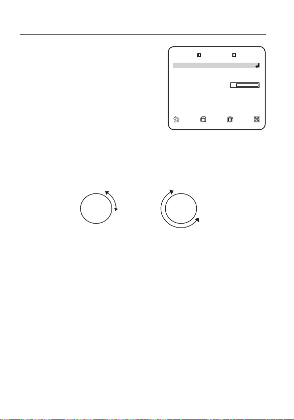
настройка
ABTO ПOB 1
HAПPABЛEHИE BЛEBO
HEПPEPЫ BHOE BЫК Л
CKOPOCT Ь
[
10
]
BЫДEPЖК A BPEM. 3S
Выберите и задайте соответствующие
3.
настройки для каждого параметра.
y
ПОЗИЦИЯ : установка начального и
конечного положения для функции
<АВТО ПОВ>.
Перейдите в экран данной
настройки и задайте необходимое
начальное положение для функций
панорамирования/наклона и нажмите
[ENTER].
Далее задайте необходимое конечное
положение для функций панорамирования/наклона и нажмите [ENTER],
чтобы завершить настройку параметра <АВТО ПОВ>.
y
НАПРАВЛЕНИЕ : установка направления перемещения камеры от начального
до конечного положения. (На основе настроек панорамирования)
<ВПРАВО><ВЛЕВО>
НАЧАЛО НАЧАЛО
ABTO ПOB 1
ПO3ИЦИЯ
HAПPAB ЛEHИE BЛEBO
HEПPEPЫBHOE BЫКЛ
CKOPOCTЬ
BЫДEPЖКA BPEM. 3S
[
10
]
КОНЕЦ
y
НЕПРЕРЫВНО : вместо перемещения между начальным и конечным
КОНЕЦ
положением камера непрерывно поворачивается на 360°,
останавливаясь в начальной и конечной точках на время, заданное для
параметра <ВЫДЕРЖКА ВРЕМ.>.
y
СКОРОСТЬ : установка скорости перемещения камеры (от 1 до 64).
y
ВЫДЕРЖКА ВРЕМ. : установка времени задержки камеры в начальном и
конечном положении (от 1 до 60 секунд).
36_ настройка

Настройка шаблона
¾
¾
УCT. ШAБЛOHA 1
HAЧAЛO
УCT. ШAБЛOHA 1
<ПO3ИЦИ Я>
CКAHИ P. 1
¾
S 1 2 3 4
5 6 7 8 9
10 11 12 13 14
15 16 17 18 19
20 21 22 23 24
25 26 27 28 29
30 31
W
1/16
X
Создание вручную двухминутного шаблона перемещения камеры в соответствии
с настройками панорамирования/наклона/трансфокации.
Способ выбора и сохранения каждого из элементов меню описан в разделе “Использование
контроллера клавиатуры”. (стр. 18)
Выберите <ОСНОВНОЕ МЕНЮ> -
1.
<УСТ. АВТО ПЕРЕМЕЩЕНИЯ>.
Выберите номер шаблона.
2.
Появится экран настройки параметра
ШАБЛОН.
Выберите <ПОЗИЦИЯ>, задайте
3.
начальное положение шаблона и
нажмите [ENTER].
Выберите <НАЧАЛО> и с помощью
4.
функций панорамирования/наклона/
трансфокации переместите камеру.
Перемещения камеры, осуществляемые
5.
вручную, будут записываться в течение 2
минут, затем автоматически произойдет
возврат к предыдущему меню.
Чтобы остановить запись и вернуться к
предыдущему меню до окончания 2 минут,
нажмите [ENTER].
<ПO3ИЦИЯ>
HAЧAЛO
<ПO3ИЦИЯ>
HAЧAЛO
УCT. ШAБЛOHA 1
УCT. ШAБЛOHA 1
Настройка сканирования
Для операции сканирования можно задать определенные предустановленные
положения.
Способ выбора и сохранения каждого из элементов меню описан в разделе “Использование
контроллера клавиатуры”. (стр. 18)
Выберите <ОСНОВНОЕ МЕНЮ> -
1.
<УСТ. АВТО ПЕРЕМЕЩЕНИЯ>.
Выберите номер сканирования.
2.
Появится экран настройки параметра
СКАНИР..
Наведите курсор на номер со значком
3.
который соответствует определенному
предустановленному значению.
Нажмите [ENTER].
4.
Рядом со значком
и соответствующее предустановленное
значение будет применено при сканировании.
Сканированные цифры для определенной страницы могут быть сохранены только на
M
соответствующей странице. Сохраните их перед переходом на следующую страницу.
[
]
появится значок [SS]
¾
0
5 6 7 8 9
10 11 12 13 14
15 16 17 18 19
20 21 22 23 24
[
]
,
¾
25 26 27 28 29
30 31
CКAHИP. 1
¾
S 1 2 3 4
1/16
W
X
Руский _37
Руский

настройка
ABTO ПPO ГPAMMA 1
ABTO ПPO ГPAMMA ПPEДУCT.
№ ШAГA ПP OГPAMMЫ 0
W
УCT. ABTO ПEPEMEЩEHИЯ
X
ABTO ПOB
1 2 3 4
ШAБЛOH
1
¾
2
¾
3
¾
CКAHИP.
1 2 3 4
ABTO ПPO ГPAMMA 2
ID: HA ЧAЛO КOHEЦ ПP O. HET.
00:00 03:00 BЫ КЛ 0
2 03:00 06:00 B ЫКЛ 0
3 06:00 09:00 B ЫКЛ 0
4 09:00 12:00 B ЫКЛ 0
5 12:00 15:00 B ЫКЛ 0
6 15:00 18:00 B ЫКЛ 0
7 18:00 21:00 B ЫКЛ 0
8 21:00 00:00 B ЫКЛ 0
Настройка авто программы
Функция АВТО ПРОГРАММА осуществляет автоматический запуск настроенных
функций АВТО ПОВ, ШАБЛОН и СКАНИР..
Способ выбора и сохранения каждого из элементов меню описан в разделе “Использование
контроллера клавиатуры”. (стр. 18)
Выберите <ОСНОВНОЕ МЕНЮ> -
1.
<УСТ. АВТО ПЕРЕМЕЩЕНИЯ>.
Выберите параметр <АВТО ПРОГРАММА>
2.
и номер.
Появится экран настройки функции АВТО
ПРОГРАММА.
y
АВТО ПРОГРАММА 1 : настройка общих
свойств функции АВТО ПРОГРАММА.
АВТО ВОЗВРАТ : установка интервала
-
между запусками авто программ.
АВТО ПРОГРАММА : для каждого
-
интервала авто программы
устанавливается операция авто
программы.
Можно выбрать с 1 по 4 операцию
для функций СКАНИР. или АВТО
ПОВ, с 1 по 3 для функции ШАБЛОН
и с 0 по 511 для параметра
ПРЕДУСТ..
ШАГА ПРОГРАММЫ : установка номера действия заданной авто
-
№
программы.
y
АВТО ПРОГРАММА 2 : выбор действия
авто программы и установка времени
его начала/окончания.
По достижении заданного времени
начала авто программа будет запущена.
Можно выбрать с 1 по 4 операцию
для функций СКАНИР. или АВТО ПОВ,
с 1 по 3 для функции ШАБЛОН и с 0
по 511 для параметра ПРЕДУСТ..
W
УCT. ABTO ПEPEMEЩEHИЯ
ABTO ПOB
ШAБЛOH
CКAHИP.
ABTO ПPOГPAMMA 1
ABTO ПPOГPAMMA 1
ABTO BOЗBPAT 1MИH.
ABTO ПPOГPAMMA ПPEДУCT.
№ ШAГA ПPOГPAMMЫ 0
ABTO ПPOГPAMMA 2
ID: HAЧAЛO КOHEЦ ПPO. HET.
1
00:00 03:00 BЫКЛ 0
2 03:00 06:00 BЫКЛ 0
3 06:00 09:00 BЫКЛ 0
4 09:00 12:00 BЫКЛ 0
5 12:00 15:00 BЫКЛ 0
6 15:00 18:00 BЫКЛ 0
7 18:00 21:00 BЫКЛ 0
8 21:00 00:00 BЫКЛ 0
1 2 3 4
1
2
¾
1 2 3 4
X
3
¾
¾
38_ настройка

УСТАНОВКА ЗОНЫ
AЗИMУT B ЫКЛ
УCT.OБЛACTИ ЗO HЫ BЫКЛ
¾¾
OCHOBH OE MEHЮ
¾¾
ПPOФИЛЬ
HACTP. КAMEPЫ
C-MA OTCЛ EЖ-Я
ЧACTHAЯ ЗOHA
ПPEДУCT.
УCT. ABTO ПEPEMEЩEHИЯ
HACTPOЙ КA TPEBOГ
УCTAH. ЧACO B
ДP. HACTPOЙКИ
КAPTA OБЛACT EЙ ЗOHЫ
2 3 4
5 6 7 8
Можно настроить северное направление и покрытие зоны.
Способ выбора и сохранения каждого из элементов меню описан в разделе “Использование
контроллера клавиатуры”. (стр. 18)
Выберите <ОСНОВНОЕ МЕНЮ> -
1.
<УСТАНОВКА ЗОНЫ>.
Для параметра <АЗИМУТ> установите
2.
значение <ВКЛ>.
3.
С помощью джойстика установите
северное направление, затем нажмите
[ENTER].
y
УСТ. СЕВЕР : В окне параметра УСТ.
СЕВЕР нажмите [ENTER], чтобы
установить северное направление,
относительно которого определяются
другие направления.
Для параметра <УCT.OБЛACTИ ЗOHЫ>
4.
установите значение <ВКЛ>.
На появившемся экране <КАРТА
5.
ОБЛАСТЕЙ ЗОНЫ> выберите номер.
6.
Появится экран <УСТ. ОБЛАСТИ
ЗОНЫ>, на котором задайте значения
для параметров <ПОЗИЦИЯ> и
<УСТ. ID ЗОНЫ>.
Для получения информации о процедуре ввода
имени см. пункт “ID КАМЕРЫ”. (стр. 22)
y
ПОЗИЦИЯ : установка левой/правой
границы зоны.
¾¾
OCHOBHOE MEHЮ
ПPOФИЛЬ
HACTP. КAMEPЫ
C-MA OTCЛEЖ-Я
ЧACTHAЯ ЗOHA
ПPEДУCT.
УCT. ABTO ПEPEMEЩEHИЯ
УCTAHOBКA ЗOHЫ
HACTPOЙКA TPEBOГ
УCTAH. ЧACOB
ДP. HACTPOЙКИ
W
УCTAHOBКA ЗOHЫ
AЗИMУT BЫКЛ
УCT.OБЛACTИ ЗOHЫ BЫКЛ
КAPTA OБЛACTEЙ ЗOHЫ
1
2 3 4
5 6 7 8
¾¾
X
Руский
Руский _39

настройка
УCT. ПP-TA TP-ГИ
УCT. BXOДA TPEB
УCT.BЫX.TPEBO ГИ
УCT. ABTO ПEPEMEЩEHИЯ
BCПOM. УПP. BЫX.
¾¾
OCHOBH OE MEHЮ
¾¾
ПPOФИЛЬ
HACTP. КAMEPЫ
C-MA OTCЛ EЖ-Я
ЧACTHAЯ ЗOHA
ПPEДУCT.
УCT. ABTO ПEPEMEЩEHИЯ
УCTAHOBКA ЗOH Ы
УCTAH. ЧACO B
ДP. HACTPOЙКИ
УCT. ПP-TA TP-ГИ
TPEBOГA 2 2
TPEBOГA 3 3
TPEBOГA 4 4
TPEBOГA 5 5
TPEBOГA 6 6
TPEBOГA 7 7
TPEBOГA 8 8
НАСТРОЙКА ТРЕВОГ
Доступны 8 входных и 3 выходных сигналов тревоги. С помощью данного параметра
отслеживаются входные сигналы тревоги, поступающие от внешних датчиков, которые
работают в соответствии с предустановленными настройками, шаблонами и функциями
сканирования, затем генерируется выходной сигнал тревоги. Время задержки сигнала
тревоги определяется соответствующим предустановленным значением для параметра
<ВЫДЕРЖКА ВРЕМ.> и действия, которое выполняется при появлении этого сигнала.
Способ выбора и сохранения каждого из элементов меню описан в разделе “Использование
контроллера клавиатуры”. (стр. 18)
Выберите <ОСНОВНОЕ МЕНЮ> -
1.
<НАСТРОИКА ТРЕВОГ>.
Выберите и задайте соответствующие
2.
настройки для каждого параметра.
y
ПРИОРИТЕТ ТРЕВОГИ : настройка
очередности сигналов тревог.
Настройка приоритета 8 тревог
определяет порядок отображения
тревожных уведомлений, начиная с
самого важного. По умолчанию порядок
приоритетов установлен следующим
образом: Тревога 1 ¨ Тревога 2 ¨ .....
Тревога 8. Когда несколько сигналов
¨
тревоги генерируются одновременно,
тревожные уведомления поступают в
порядке приоритетов, установленных
по умолчанию. При создании сигнала
тревоги движения объектов не отслеживаются.
40_ настройка
¾¾
OCHOBHOE MEHЮ
ПPOФИЛЬ
HACTP. КAMEPЫ
C-MA OTCЛEЖ-Я
ЧACTHAЯ ЗOHA
ПPEДУCT.
УCT. ABTO ПEPEMEЩEHИЯ
УCTAHOBКA ЗOHЫ
HACTPOЙКA TPEBOГ
УCTAH. ЧACOB
ДP. HACTPOЙКИ
W
HACTPOЙКA TPEBOГ
УCT. ПP-TA TP-ГИ
УCT. BXOДA TPEB
УCT.BЫX.TPEBOГИ
УCT. ABTO ПEPEMEЩEHИЯ
BCПOM. УПP. B ЫX.
УCT. ПP-TA TP-ГИ
TPEBOГA1 1
TPEBOГA2 2
TPEBOГA3 3
TPEBOГA4 4
TPEBOГA5 5
TPEBOГA6 6
TPEBOГA7 7
TPEBOГA8 8
¾¾
X

y
BCПOM . УПP. BЫX.
BЫXOД2 BЫКЛ
BЫXOД3 BЫКЛ
УCT. ABTO ПEPEMEЩEHИЯ
TPEBOГA 2 BЫКЛ
TPEBOГA 3 BЫКЛ
TPEBOГA 4 BЫКЛ
TPEBOГA 5 BЫКЛ
TPEBOГA 6 BЫКЛ
TPEBOГA 7 BЫКЛ
TPEBOГA 8 BЫКЛ
ДBИЖEHИ E B ЫКЛ
УСТ. ВХОДА ТРЕВ : выбор работы датчика тревоги: <НЕТ>, <НЗ> и <ВЫКЛ>.
y
УСТ. ВЫХ. ТРЕВОГИ : настройка порта выхода сигнала, совместимого с
портом входа сигнала.
y
УСТ. АВТО ПЕРЕМЕЩЕНИЯ : настройка
шаблона и операций сканирования
для соответствующего входного
сигнала тревоги. При возникновении
сигнала тревоги камера перемещается
в установленное положение, заданное
для соответствующего сигнала
Предустановленные значения с 1 по
8 соответствуют входным сигналам
тревоги с 1 по 8, предустановленное
УCT. ABTO ПEPEMEЩEHИЯ
TPEBOГA1 BЫКЛ
TPEBOГA2 BЫКЛ
TPEBOГA3 BЫКЛ
TPEBOГA4 BЫКЛ
TPEBOГA5 BЫКЛ
TPEBOГA6 BЫКЛ
TPEBOГA7 BЫКЛ
TPEBOГA8 BЫКЛ
ДBИЖEHИE BЫКЛ
значение 9 связано с функцией
обнаружения движения. Камера останавливается и остается в данном
предварительно заданном положении в течение времени, указанном
для параметра <ВЫДЕРЖКА ВРЕМ.>, и выполняет действия, заданные
шаблоном, или операцию сканирования в соответствии с настройками
параметра <УСТ. АВТО ПЕРЕМЕЩЕНИЯ>.
После перемещения камеры в заданное положение действия, заданные
шаблоном, или операция сканирования не будут выполняться, если для
параметра установлено значение <ВЫКЛ>.
- Шаблон 1 - 3: определение действий шаблона
- ПОЛОВ.1 : последовательное выполнение шаблонов 1 и 2
- ПОЛОВ.2 : последовательное выполнение шаблонов 2 и 3
- ВЕСЬ : последовательное выполнение шаблонов 1, 2 и 3
Сканир. 1 - 4 : предварительно заданные операции для параметра СКАНИР.
-
Параметр <ALARM1> используется в качестве внешнего сигнала переключения, если
M
для параметра <ДЕНЬ/НОЧЬ> установлено значение <ВНЕШНИЙ>.
y
ВСПОМ. УПР. ВЫХ. : настройка либо
для сохранения передачи выходного
сигнала тревоги независимо от
генерации датчиком сигнала тревоги,
или для вывода сигнала тревоги,
BCПOM. УПP. BЫX.
BЫXOД1 BЫКЛ
BЫXOД2 BЫКЛ
BЫXOД3 BЫКЛ
только пока данный сигнал поступает
с датчика.
Если для данного параметра
установлено значение <ВЫКЛ>,
сигнал тревоги выдается, только когда
тревога генерируется датчиком. Если
для данного параметра установлено значение <ВКЛ>, сигнал тревоги
будет выдаваться постоянно независимо от того, генерируется тревога
или нет.
Руский
Руский _41

настройка
3ABOД.У CTAH.
ЦBETHOE Ч-Б
ПPOПOPЦ .ПOB/HA K BК Л
ПOB/HAK CKOPOC TЬ
[
2
]
ABTO КAЛ . BЫКЛ
ПEPEBOP OT BЫ КЛ
ПAPOЛЬ BЫКЛ
ДИCПЛEЙ B ЫКЛ
ФOPMAT BPEM . 12ЧAC
УCTAH.BPEME HИ AM 0 7:34:48
ФOPMAT ДATЫ MM/DD/Y YYY
УCTAH. ДATЫ 01/01/2009
УСТАН. ЧАСОВ
Данная настройка определяет, требуется ли отображать часы на экране, и задает
формат времени.
Способ выбора и сохранения каждого из элементов меню описан в разделе “Использование
контроллера клавиатуры”. (стр. 18)
Выберите <ОСНОВНОЕ МЕНЮ> -
1.
<УСТАН. ЧАСОВ>.
2.
Выберите <ДИСПЛЕЙ> и установите,
требуется ли отображать время на
экране.
3.
Выберите формат времени и выставите
его значение на часах.
4.
Выберите формат даты и установите
дату.
ДP. HACTPOЙКИ
Можно выполнить сброс установок системы до настроек по умолчанию, запустив
ЗАВОД.УСТАН, или настроить цвет шрифта, трансфокацию, высокую скорость
панорамирования/наклона и т.д.
Способ выбора и сохранения каждого из элементов меню описан в разделе “Использование
контроллера клавиатуры”. (стр. 18)
Выберите <ОСНОВНОЕ МЕНЮ> -
1.
<ДР. НАСТРОЙКИ>.
2.
Выберите и задайте соответствующие
настройки для каждого параметра.
W
УCTAH. ЧACOB
ДИCПЛEЙ BЫКЛ
ФOPMAT BPEM. 12ЧAC
УCTAH.BPEMEHИ AM 07:34:48
ФOPMAT ДATЫ MM/DD/YYYY
УCTAH. ДATЫ 01/01/2009
W
ДP. HACTPOЙКИ
3ABOД.УCTAH.
ЦBETHOE Ч-Б
ПPOПOPЦ.ПOB/HAK BКЛ
ПOB/HAK CKOPOCTЬ
ABTO КAЛ. BЫКЛ
ПEPEBOPOT BЫКЛ
ПAPOЛЬ BЫКЛ
X
X
[
]
2
42_ настройка

ЗАВОД.УСТАН.
3ABOД .УCTAH.
OK
ПAPOЛ Ь
1 2 3 4
5 6 7 8 9
[
¾¾¾
]
[
¾¾¾¾
]
При выборе параметра <ЗАВОД.УСТАН.>
появится экран, на котором, нажав <OK>,
можно выполнить сброс всех настроек до
заводских установок по умолчанию.
Однако для таких параметров, как протокол,
скорость передачи данных в бодах,
адрес и язык, заводские настройки не
восстанавливаются.
Обратите внимание, когда выполняется сброс
M
настроек системы до заводских настроек по
умолчанию, все данные настройки будут удалены.
3ABOД.УCTAH.
OK
OTMEHA
ЦВЕТНОЕ
Выбор цвета шрифта экранного меню.
ПРОПОРЦ.ПOB/HAK
Если для данного параметра установлено значение <ВКЛ>, скорость
панорамирования/наклона в ручном режиме изменяется пропорционально
коэффициенту трансфокации.
ПОВ/НАК СКОРОСТЬ
Если для данного параметра установлено значение <ВКЛ>, скорость
панорамирования/наклона в ручном режиме увеличивается в два раза.
ABTO КAЛ. (АВТО КОРРЕКЦИЯ)
Для настройки объектива и точности работы привода панорамирования/
наклона используется функция автоматической компенсации. Произойдет
автоматический сброс настроек объектива и панорамирования/наклона, если в
течение определенного периода времени не выполняются никакие операции.
ПЕРЕВОРОТ
Если для этого параметра выбрано значение <ВКЛ>, то при повороте объекта
более чем на 90° изображение на экране повернется по вертикали или по
горизонтали соответственно.
ПАРОЛЬ
Если для этого параметра выбрать значение
<ВКЛ>, то для доступа в меню необходимо
будет ввести пароль.
Выберите необходимые цифры, используя
кнопки со стрелками, и нажмите [ENTER].
Пароль по умолчанию - "4321".
0
5 6 7 8 9
ПAPOЛЬ
1 2 3 4
[
]
¾
¾¾¾
[
]
¾¾¾¾
Руский
Руский _43

настройка
RS485
ПPИOPИT ET HW
ПPOTOКOЛ SAM SUNG
ПOЛOB.
CКOPOCT Ь(БOД) 9600
AДPEC 0
TИП 4
_
PTZ
_
WDR
_
P
ПPOTOКOЛ SAMSUNG
AДPEC 0
TИП CBЯ ЗИ HW, RS485 , ПOЛOB .
CКOPOCT Ь(БOД) 9600
CEPИЙHЫ Й № 000000000000000
BEPC. К AMEPЫ v1.00
_
00000
BEPC. C ИГHAЛИЗ . v1.00
_
00000
СВЯЗЬ
Для некоторых моделей камеры можно задать настройки, присущие протоколу
связи RS-485.
Способ выбора и сохранения каждого из элементов меню описан в разделе “Использование
контроллера клавиатуры”. (стр. 18)
Выберите <ОСНОВНОЕ МЕНЮ> -
1.
<СВЯЗЬ>.
2.
Выберите и задайте соответствующие
настройки для каждого параметра.
y
ПРИОРИТЕТ : задайте приоритет,
выбрав <HW> или <SW>.
Если выбрано значение <HW>, то
RS485
ПPИOPИTET HW
ПPOTOКOЛ SAMSUNG
ПOЛOB.
CКOPOCTЬ(БO Д) 9600
AДPEC 0
настройки протокола, скорости в
бодах и адреса будут такими же, как
при использовании адаптера.
y
ПРОТОКОЛ, CКOPOCTЬ(БOД), АДРЕС :
при выборе значения <SW> значения, имеющие отношение к протоколу,
скорости в бодах и адресу, можно задать вручную.
ИHФ. O CИCTEME
В этом меню можно просмотреть сведения о системе.
Способ выбора и сохранения каждого из элементов меню описан в разделе “Использование
контроллера клавиатуры”. (стр. 18)
Выберите <ОСНОВНОЕ МЕНЮ> -
1.
<ИHФ. O CИCTEME>.
2.
Отображается текущая информация о
системе.
TИП 4
ПPOTOКOЛ SAMSUNG
AДPEC 0
TИП CBЯЗИ HW, RS485, ПO ЛOB.
CКOPOCTЬ(БOД ) 9600
CEPИЙHЫЙ № 000000000000000
BEPC. КAMEPЫ v1.00
BEPC. CИГHAЛИЗ. v1.00
W
CBЯЗЬ
W
ИHФ. O CИCTEME
X
X
_
_
_
PTZ
WDR
_
00000
_
00000
P
44_ настройка

ЯЗЫК
ENGLISH
¾
PУCCKNЙ
POLSKI
ČESKY
TÜRKÇE
В этом меню можно выбрать язык интерфейса пользователя.
Способ выбора и сохранения каждого из элементов меню описан в разделе “Использование
контроллера клавиатуры”. (стр. 18)
Выберите <ОСНОВНОЕ МЕНЮ> -
1.
<ЯЗЫК>.
Используя кнопки со стрелками вверх/
2.
вниз, выберите язык.
W
ЯЗЫК
ENGLISH
¾
PУCCKNЙ
POLSKI
ČESKY
TÜRKÇE
X
Руский
Руский _45

приложение
КЛАВИШИ БЫСТРОГО ДОСТУПА
Функция Клавиша
ДЕНЬ/НОЧЬ - ДЕНЬ [PRESET] + [5] + [1] + [2] + [ENTER]
ДЕНЬ/НОЧЬ - НОЧЬ [PRESET] + [5] + [1] + [3] + [ENTER]
ДЕНЬ/НОЧЬ - АВТО [PRESET] + [5] + [1] + [4] + [ENTER]
ДЕНЬ/НОЧЬ - ВНЕШНИЙ [PRESET] + [5] + [1] + [5] + [ENTER]
HACTP.
КAMEPЫ
НАСТРОЙКА
ТРЕВОГ
HACTPOЙКИ
УСТ. АВТО
ПЕРЕМЕЩЕНИЯ
ФУНКЦИЯ Запуск автоматической калибровки [PRESET] + [5] + [3] + [8] + [ENTER]
ДИАФРАГМА – ALC – ФOHOB.CBET – WDR [PRESET] + [5] + [1] + [6] + [ENTER]
ДИАФРАГМА – ALC – ФOHOB.CBET – ВЫКЛ [PRESET] + [5] + [1] + [7] + [ENTER]
ДИАФРАГМА - ALC [PRESET] + [5] + [1] + [8] + [ENTER]
ДИАФРАГМА - РУЧН. [PRESET] + [5] + [1] + [9] + [ENTER]
PEЖИM ФOКУC. – АФ [PRESET] + [5] + [2] + [0] + [ENTER]
PEЖИM ФOКУC. – РФ [PRESET] + [5] + [2] + [1] + [ENTER]
PEЖИM ФOКУC. – OДHOКP. AФ [PRESET] + [5] + [2] + [2] + [ENTER]
ВСПОМ. УПР. ВЫХ. – BЫXOД1 – ВКЛ [PRESET] + [5] + [2] + [3] + [ENTER]
ВСПОМ. УПР. ВЫХ. – BЫXOД1 – ВЫКЛ [PRESET] + [5] + [2] + [4] + [ENTER]
ВСПОМ. УПР. ВЫХ. – BЫXOД2 – ВКЛ [PRESET] + [5] + [2] + [5] + [ENTER]
ВСПОМ. УПР. ВЫХ. – BЫXOД2 – ВЫКЛ [PRESET] + [5] + [2] + [6] + [ENTER]
ВСПОМ. УПР. ВЫХ. – BЫXOД3 – ВКЛ [PRESET] + [5] + [2] + [7] + [ENTER]
ВСПОМ. УПР. ВЫХ. – BЫXOД3 – ВЫКЛ [PRESET] + [5] + [2] + [8] + [ENTER]
ПРОПОРЦ.ПOB/HAK – ВКЛ [PRESET] + [5] + [2] + [9] + [ENTER]
ПРОПОРЦ.ПOB/HAK – ВЫКЛ [PRESET] + [5] + [3] + [0] + [ENTER]
ДP.
ПОВ/НАК СКОРОСТЬ – 9 [PRESET] + [5] + [3] + [1] + [ENTER]
ПОВ/НАК СКОРОСТЬ – 5 [PRESET] + [5] + [3] + [2] + [ENTER]
ПЕРЕВОРОТ – ВКЛ [PRESET] + [5] + [3] + [3] + [ENTER]
ПЕРЕВОРОТ – ВЫКЛ [PRESET] + [5] + [3] + [4] + [ENTER]
АВТО ПРОГРАММА – 1 [PRESET] + [5] + [3] + [5] + [ENTER]
АВТО ПРОГРАММА – 2 [PRESET] + [5] + [3] + [6] + [ENTER]
АВТО ПРОГРАММА – ВЫКЛ [PRESET] + [5] + [3] + [7] + [ENTER]
46_ приложение

ТЕХНИЧЕСКИЕ ХАРАКТЕРИСТИКИ
Элемент Описание
Тип изделия КАМЕРА SMART DOME
Источник питания 24 В переменного тока (50 Гц)
Потребляемая мощность 11.5W
Стандарт телевещания СИСТЕМА ЦВЕТНОСТИ СТАНДАРТА PAL
Датчик изображения матрица ExView-HAD PS CCD
Количество эффективных
пикселей
Частота развертки
Синхронизация ВНУТР/ЗАБЛОКИРОВАНО
Разрешение
Соотношение сигнал/шум Приблизительно равен 52 дБ
Минимальная освещенность
объекта съемки
WDR x128
Выход сигнала КОМПОЗИТНЫЙ ВИДЕОВЫХОД : 1,0 В 75 Ом/BNC
Объектив
752(H) Ч 582(V)
По горизонтали : 15, 625 Гц (INT) (ВНУТР) / 15, 625 Гц (L/L)
По вертикали : 50 Гц (INT) (ВНУТР) / 50 Гц (L/L)
По горизонтали : 600 ТЕЛЕВИЗИОННЫХ ЛИНИЙ
По вертикали : 350 ТЕЛЕВИЗИОННЫХ ЛИНИЙ
НАКОПЛЕНИЕ Освещение Цветной Ч-Б режим
Выкл. 50 IRE 1,2 0,12
Выкл. 30 IRE 0,72 0,072
Выкл. 15 IRE 0,36 0,036
x512 50 IRE 0,0023 0,00023
x512 30 IRE 0,0014 0,00014
x512 15 IRE 0,0007 0,00007
Встроенный объектив с 25-кратным увеличением
Фокусное расстояние 3,66 - 91,36 мм
Диафрагма : F1.65 (широкоугольный), F3.0 (теле)
- MOD (Минимальное расстояние до объекта) : 100 мм
Руский
Руский _47

приложение
Элемент Описание
Диапазон панорамирования : 360° (непрерывное)
ПАНОРАМИРОВАНИЕ
НАКЛОН
Пульт ДУ
Тревога
Рабочая температура -10°C ~ +50°C
Влажность при работе ~90%
Размеры (Д x В) 178 (Д) x 219 (В) мм
Вес 1,85 кг
Цвет устройства Светло-серый
Предварительно заданная скорость панорамирования : максимум 600°
/сек
Скорость панорамирования вручную : от 0,01° до 180°/сек
Диапазон угла наклона : -6°~186°
Предустановленная скорость наклона : максимум 600°/сек
Ручная скорость наклона : от 0,01° до 180°/сек
RS-485 (полудуплексный и дуплексный)/RS-422,
передача данных через коаксиальный кабель
Входы сигналов тревоги : 8 входов IN
Выводы сигналов тревоги : 3 вывода OUT (2 - разомкнутый коллектор и
1 - реле)
48_ приложение

ВНЕШНИЙ ВИД УСТРОЙСТВА
Руский
Руский _49

Правильная утилизация данного устройства
(Действует во всех странах Европейского Союза и других странах Европы, принявших систему разделения отходов)
Подобная маркировка на изделии, принадлежностях или в руководстве к нему предупреждает, что по истечении срока
службы изделие или электронные принадлежности для него (например, зарядное устройство, наушники, кабель USB) не
следует выбрасывать вместе с другим бытовым мусором. Чтобы избежать вредного воздействия на окружающую среду
или на здоровье человека от неконтролируемой утилизации отходов, следует отделять маркированные подобным образом
изделия от другого мусора для соответствующей переработки и повторного использования в качестве сырья.
За подробной информацией о месте и способе экологически безопасной утилизации бытовым потребителям следует
обращаться к продавцу данного изделия или в органы местного самоуправления.
Промышленным потребителям необходимо обратиться к поставщику, чтобы уточнить сроки и условия договора купли-продажи.
Подобные изделия и электронные принадлежности не следует утилизировать вместе с другими производственными отходами.
Подлежит использованию по назначению
в нормальных условиях
Срок службы : 7 лет.
(Утилизация электрического и электронного оборудования)
 Loading...