

Page 1
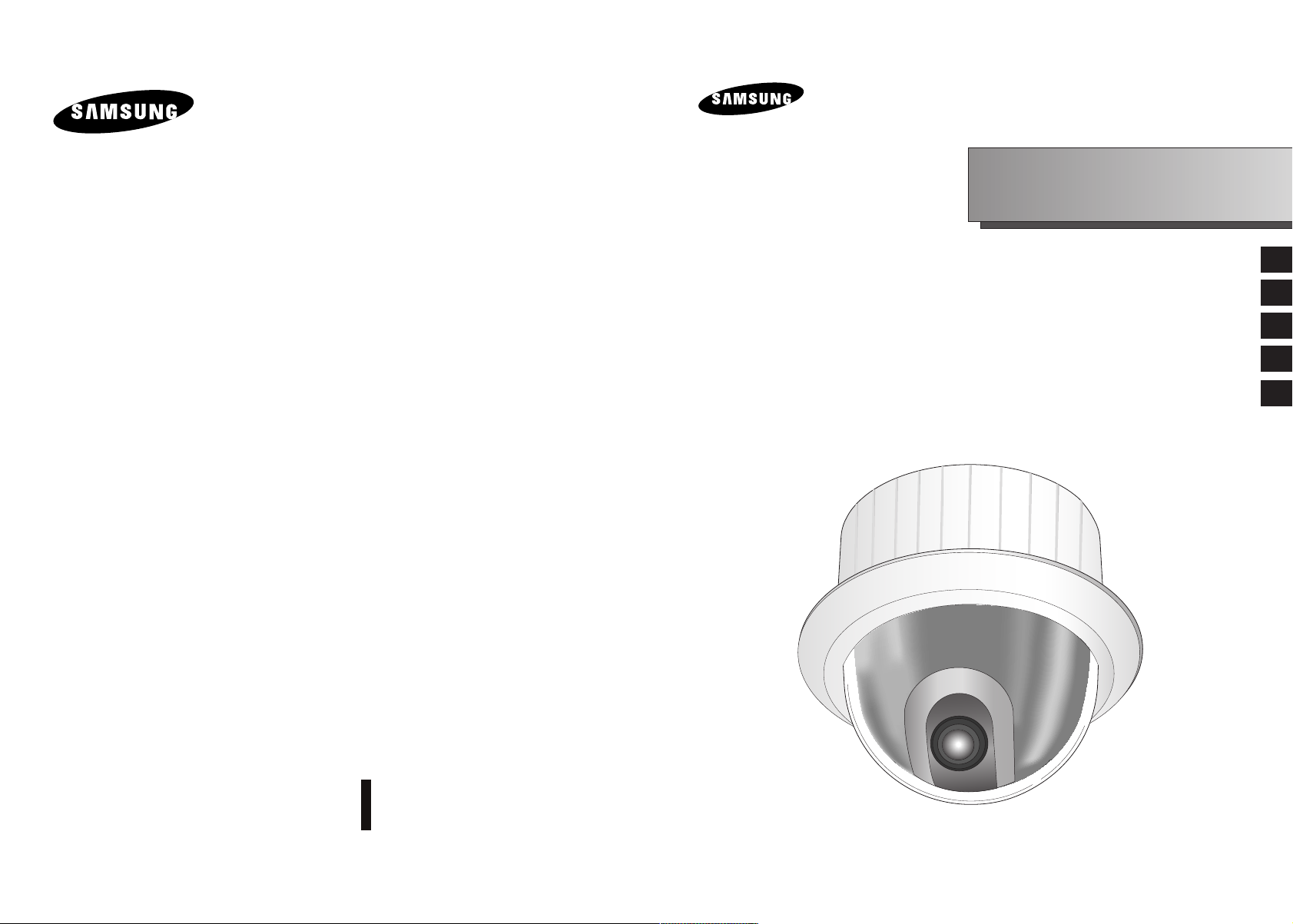
SmartDome Camera
SCC-C6407(P)
Owner’s Instructions
Benutzerhandbuch
Manuel d’instruction
Manual del usuario
Istruzioni per l’uso
E
D
F
Es
I
Part : AB68-00547A(00)
Printed in China
Page 2
Important Safety Instructions
Safety Precautions
1. Read these instructions.
2. Keep these instructions.
3. Heed all warnings.
4. Follow all instructions.
5. Do not use this apparatus near water.
6. Clean only with dry cloth.
7. Do not block any ventilation openings, Install in accordance with the
manufacturer's instructions.
8. Do not install near any heat sources such as radiators, heat registers, or
other apparatus (including amplifiers) that produce heat.
9. Do not defeat the safety purpose of the polarized or grounding- type plug.
A polarized plug has two blades with one wider than the other.
A grounding type plug has two blades and a third grounding prong.
The wide blade or the third prong are provided for your safety. If the
provided plug does not fit into your outlet, consult an electrician for
replacement of the obsolete outlet.
10. Protect the power cord from being walked on or pinched particularly at
plugs, convenience receptacles, and the point where they exit from the
apparatus.
11. Only use attachments/accessories specified by the manufacturer.
12. Use only with cart, stand, tripod, bracket, or table specified by the
manufacturer, or sold with the apparatus.
13. Unplug this apparatus. When a cart is used, use caution when moving the
cart/apparatus combination to avoid injury from tip-over.
14. Refer all servicing to qualified service personnel. Servicing is required
when the apparatus has been damaged in any way, such as power-supply
cord or plug is damaged, liquid has been spilled or objects have fallen into
the apparatus the apparatus has been exposed to rain or moisture, does
not operate normally, or has been dropped.
The purpose of this information is to ensure proper use of this product to
prevent danger or damage to property. Please be sure to observe all
precautions.
* The precautions are divided into "Warnings" and "Cautions" as
distinguished below:
Warning: Ignoring this warning may result in death or serious injury.
Caution: Ignoring this caution may result in injury or damage to property.
Warning instructions alert you to
a potential risk of death
or serious injury.
Caution instructions alert you to the
potential risk of injury or
damage to property.
Warning
1. Be sure to use only the standard adapter which is specified in the
specification sheet.
Using any other adapter could cause fire, electrical shock, or damage to
the product.
2. When connecting the power supply and signal wires, check the external
connection terminals before connecting them. Connect the alarm signal
wires to the alarm terminals, the AC adapter to the AC power input
receptacle, and the DC adapter to the DC power input, making sure that
the correct polarity is observed.
(Connecting the power supply incorrectly may cause fire, electrical shock,
or damage to the product.)
3. Do not connect multiple cameras to a single adapter.
(Exceeding the capacity may cause abnormal heat generation or fire.)
(A falling camera may cause personal injury.)
4. Securely plug the power cord into the power receptacle.
(Insecure connection may cause fire.)
E
5. When installing the camera on a wall or ceiling, fasten it securely and
firmly. (A falling camera may cause personal injury.)
Page 3

6. Do not place conductive objects (e.g., screwdrivers, coins, and metal
things) or containers filled with water on top of the camera. (Doing so may
cause personal injury due to fire, electrical shock, or falling objects.)
7. Do not install the unit in humid, dusty, or sooty locations.
(Doing so may cause fire or electrical shock.)
8. If any unusual smells or smoke come from the unit, stop using the product.
In such case, immediately disconnect the power source and contact the
service center. (Continued use in such a condition may cause fire or
electrical shock.)
9. If this product fails to operate normally, contact the store of purchase or
your nearest service center. Never disassemble or modify this product in
any way. (SAMSUNG is not liable for problems caused by unauthorized
modifications or attempted repair.)
10. When cleaning, do not spray water directly onto parts of the product.
(Doing so may cause fire or electrical shock.)
Wipe the surface with a dry cloth. Never use detergents or chemical
cleaners on the product, as this may result in discoloration of surface or
cause damage to the finish.
Caution
FCC STATEMENT
This device complies with Part 15 of the FCC Rules. Operation is subject to
the following two conditions:
(1) This device may not cause harmful interference, and
(2) This device must accept any interference received, including interference
that may cause undesired operation.
Note: This equipment has been tested and found to comply with the limits for
a Class A digital device, pursuant to part 15 of the FCC Rules. These
limits are designed to provide reasonable protection against harmful
interference when the equipment is operated in a commercial
environment. This equipment generates, uses, and can radiate radio
frequency energy and, if not installed and used in accordance with the
instruction manual, may cause harmful interference to radio
communications. Operation of this equipment in a residential area is
likely to cause harmful interference in which case the user will be
required to correct the interference at his own expense.
1. Do not drop objects on the product or apply strong shock to it. Keep away
from a location subject to excessive vibration or magnetic interference.
2. Do not install in a location subject to high temperature (over
temperature (below 14°F
(Doing so may cause fire or electrical shock.)
3. Avoid a location which is exposed to direct sunlight, or near heat sources
such as heaters or radiators.
(Neglecting to do so may result in a risk of fire.)
4. If you want to relocate the already installed product, be sure to turn off the
power and then move or reinstall it.
5. Install in a well-ventilated location.
6. Remove the power plug from the outlet when there is a lightning storm.
(Neglecting to do so may cause fire or damage to the product.)
), or high humidity.
122°F), low
Page 4

Before Usage
This is a basic instruction manual for the SCC-C6407(P) user.
It contains all the instructions needed to use the SCC-C6407(P)
from a simple introduction of the control locations and functions of
the SCC-C6407(P) to installation methods in the set up menu.
We recommend all users of the SCC-C6407(P) from the
advanced user who has used similar cameras before to the
general user to read the instruction manual before using.
The most frequently used feature in the SCC-C6407(P) would be
the SCC-C6407(P) Setup Menu.
The SCC-C6407(P) Setup Menu is explained in detailed in
"Chapter 3 Setup Menu Overview".
The instructional manual is best used when read from beginning
to end, but for users wanting to read only the part they need here
are the Chapter summaries.
"Chapter 1 SCC-C6407(P) Overview" includes a brief
introduction of the SCC-C6407(P), part names and functions, and
Switch Settings.
"Chapter 2 SCC-C6407(P) Installation" explains the installation
procedures of the SCC-C6407(P) and provides preparation and
installation environment requirements.
"Chapter 3 Setup Menu Overview" presents the structure of the
Setup menu for the SCC-C6407(P) including a detailed
explanation of the functions performed in each submenu.
E
"Appendix SCC-C6407(P) Product Specifications" contains
product specifications of the SCC-C6407(P) in itemized
categories.
1-1
1-2
Page 5

Table of contents
Before Usage...............................................................................................1-1
Chapter 1 SCC-C6407(P) Overview
SCC-C6407(P) Introduction ...........................................................1-6
Locations of Control .......................................................................1-7
FRONT...........................................................................................1-7
BACK .............................................................................................1-8
ADAPTER CONNECTION.............................................................1-9
INITIAL SETTING............................................................................................1-10
Setting RS-422A/RS-485 termination ............................................1-11
Chapter 2 SCC-C6407(P) Installation
Before Installing .............................................................................2-2
Preparing the Cables .....................................................................2-3
Cable Connection ..........................................................................2-4
Installing SCC-C6407(P)................................................................2-5
Installing the Camera .....................................................................2-8
Chapter 3 Setup Menu Overview
Structure of the Setup Menu ..........................................................3-2
1. CAMERA SET ...........................................................................3-4
- CAMERA ID.............................................................................3-4
- V-SYNC ...................................................................................3-5
- COLOR/BW .............................................................................3-6
- MOTION DET ..........................................................................3-7
- ZOOM SPEED.........................................................................3-8
- DIGITAL ZOOM.......................................................................3-9
- EXIT.........................................................................................3-9
2. VIDEO SET ...............................................................................3-9
- IRIS..........................................................................................3-9
- ALC.......................................................................................3-9
- BLC.......................................................................................3-10
- WDR .....................................................................................3-11
- MANU ...................................................................................3-12
- SHUTTER................................................................................3-12
- AGC.........................................................................................3-13
- MOTION ..................................................................................3-13
- WHITE BAL .............................................................................3-14
- DIS...........................................................................................3-15
- FOCUS MODE ........................................................................3-16
- SPECIAL..................................................................................3-16
- EXIT.........................................................................................3-16
3. PRESET.....................................................................................3-17
- POSITION SET........................................................................3-18
- PRESET ID..............................................................................3-18
- VIDEO SET..............................................................................3-18
- PRESET SPEED .....................................................................3-18
- DWELL TIME...........................................................................3-18
- IMAGE HOLD ..........................................................................3-18
- EXIT.........................................................................................3-18
............................................................1-5
.........................................................2-1
................................................................3-1
4. ZONE SET ..................................................................................3-19
- PRIVACY ZONE .......................................................................3-19
- STYLE....................................................................................3-19
- BLANK ALL ABOVE...............................................................3-20
- BLANK ALL BELOW ..............................................................3-20
- PRYVACY ZONE MAP ..........................................................3-20
- SET ZONE AREA ...............................................................3-21
- SET ZOOM .........................................................................3-22
- REVERSE...........................................................................3-22
- EXIT ....................................................................................3-22
- ZONE DIR SET/ZONE AREA SET ...........................................3-22
- ZONE DIR SET.........................................................................3-23
- ZONE AREA .............................................................................3-23
- LOCATION.............................................................................3-24
- ZONE ID SET.........................................................................3-24
- ZONE ENABLE ......................................................................3-24
5. AUTO SET ..................................................................................3-25
- AUTO PAN................................................................................3-25
- POSITION SET......................................................................3-25
- DIRECTION ...........................................................................3-26
- ENDLESS ..............................................................................3-26
- SPEED...................................................................................3-26
- DWELL TIME .........................................................................3-26
- PATTERN .................................................................................3-26
- SCAN ........................................................................................3-27
- AUTO PLAY ..............................................................................3-28
- AUTO RETURN .....................................................................3-28
- AUTO PLAY ...........................................................................3-28
- PLAY NUMBER .....................................................................3-28
6. ALARM SET ................................................................................3-29
- ALARM PRIORITY SET............................................................3-29
- ALARM IN SET .........................................................................3-29
- ALARM OUT SET .....................................................................3-29
- AUTO SET ................................................................................3-30
- AUX OUT CONTROL................................................................3-30
7. OTHER SET................................................................................3-30
- PROPORTINAL P/T..................................................................3-30
- TURBO P/T ...............................................................................3-31
- AUTO CAL ................................................................................3-31
- D-FLIP.......................................................................................3-31
- CAM RESET .............................................................................3-31
- LANGUAGE ..............................................................................3-31
- PASSWORD .............................................................................3-31
8. SYSTEM INFO ............................................................................3-32
9. SHORT KEYS .............................................................................3-33
Product specifications ............................................................................3-35
E
1-3
1-4
Page 6

Chapter 1 SCC-C6407(P) Overview
In this chapter we will briefly introduce the SCC-C6407(P) and
show main functions, locations of control and Switch Setting.
SCC-C6407(P) Introduction
SCC-C6407(P) is a zoom lens built in smart dome camera which
provides you with the best monitoring function in connection with
CCTV at banks or companies.
E
The SCC-C6407(P) is a high quality surveillance camera using x32
zoom lens and digital zoom IC, it can catch clear images up to 320
times.
SCC-C6407(P) has a variety of functions such as;
- WDR to cover the full screen irregardless of its brightness,
- DAY/NIGHT to improve the sensitivity by automatic conversion
into the black and white mode at night or in the environment with
low illumination,
- White Balance to control the brightness to the illumination,
- Backlight Compensation under spotlight or utmost bright
illumination,
- Auto Focus to automatically adjust the focus to the subject
movement,
- Privacy zone to hide a specific area for personal privacy, and,
- PAN/TILT for precise control at high speed.
The SCC-C6407(P) uses an Alarm function for alert situations and
moving camera in the direction you want, ZOOM-IN and
ZOOM-OUT functions can be remote controlled.
1-5
1-6
Page 7

Locations of Control
FRONT
BACK
E
1-7
1-8
Page 8

(x100) (x10) (x1)
SW704
ON
1 2 3 4 5 6 7 8
SW701 SW702 SW703
SEE INSTRUCTION MANUAL
ADAPTER CONNECTION
SCC-C6407(P) Adapter BOARD
INITIAL SETTING
CAMERA ADDRESS SETUP
Use SW701, SW702, or 703 for Camera Address setup. You may allocate
up to 255 addresses by using SW701 to set the 3rd digit, SW702 the 2nd
digit, and SW703 the 1st digit.
EX) In case of Camera Address 1, see the following figure for setup.
SW701
SW702
Setting communication Protocol
Use number 1~4 PIN of SW704 to set communication Protocol.
PIN
PIN1 PIN2 PIN3 PIN4
Comp
A OFF OFF OFF OFF
B ON OFF OFF OFF
C OFF ON OFF OFF
D ON ON OFF OFF
E OFF OFF ON OFF
F ON OFF ON OFF
G OFF ON ON OFF
HONONONOFF
I OFF OFF OFF ON
J ON OFF OFF ON
K OFF ON OFF ON
LONONOFFON
M OFF OFF ON ON
NONOFFONON
O OFF ON ON ON
PONONONON
SW703
A : SAMSUNG HALF
B : SAMSUNG FULL
(BOTTOM VIEW)
E
1-9
Baud Rate Setting
Use PIN 5 and 6 of SW704.
1 2 3 4 5 6 7 8
ON
OFF
SW 704
BAUD RATE
4800 BPS
9600 BPS
19200 BPS
38400 BPS
PIN 5
ON
OFF
ON
OFF
The factory default setting is set to 9600BPS.
PIN 6
ON
ON
OFF
OFF
1-10
Page 9

Setting RS-422A/RS-485 termination
As it is shown in the structure map, when Controller and RS-422A/RS485 is connected it should be terminated according to the Cable feature
of impedance on the each end of the transmitting line to transfer the
signals in long distance by controlling the reflection of the signals to the
lowest.
Division
<RS-485 Half Duplex Organization>
Termination: using numbers 1 and 2 PIN, turn to ON and it will be terminated.
n < 32
Termination
SW1-ON
Chapter 2 SCC-C6407(P) Installation
In this chapter, we will check the contents of the package before
installing the SCC-C6407(P), and prepare a power adapter suitable
for the power supply system.
(Power Consumption: 22W; Voltage: AC24V, 1.5A)
Then, we will install the SCC-C6407(P) and connect the cables.
E
1-11
Division
<RS-422A/RS-485 Full Duplex Organization>
n < 32
Division
SW1-ON
SW2-ON
2-1
Page 10

Before Installing
Preparing the Cables
Checking Package Contents
Please check that all components listed below are included in the package:
SCC-C6407(P)
Bracket anchor
Owner’s
Instructions
Screws
Cover Body
To install and use the SCC-C6407(P), the following cables should be
prepared.
Power Adapter Cable
The cable that plugs into the SCC-C6407(P) power input receptacle has
the rated voltage of AC24V, 1.5A.
Check the rated voltage before using the cable.
Video Cable
The SCC-C6407(P)'s cable is a BNC Cable for connecting the videooutput terminal to the video-input terminal of the monitor.
E
2-2
Camera Holder
Adapter Board
2-3
Page 11
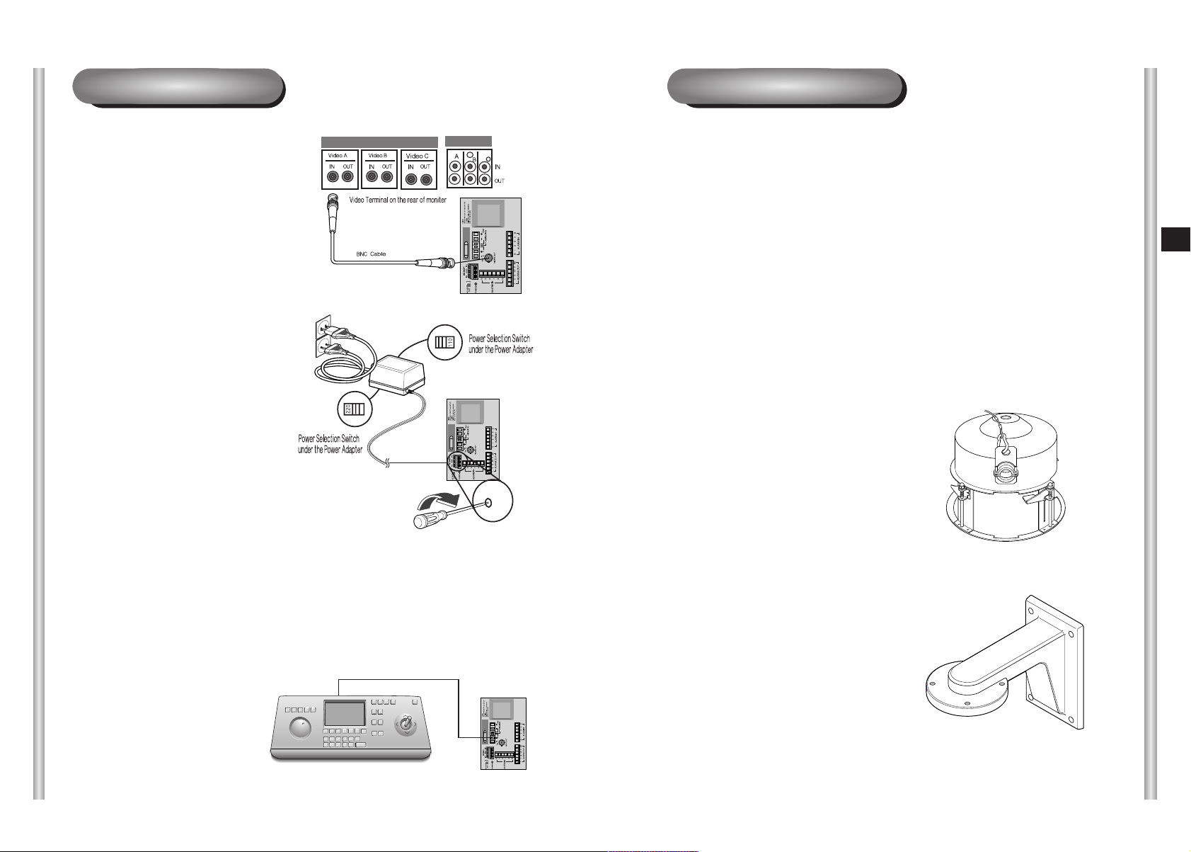
Cable Connection
Installing SCC-C6407(P)
1. First, connect one end of the
BNC video cable connector to
the Video Output Terminal
(VIDEO OUT)
2. Then, connect the other end of
the connector to the Video Input
Terminal of the monitor.
3. Now connect the Power Adapter
Cable. Use a driver to screw
one part of the two lines of
Power Adapter to Power Input
Terminal of the SCC-C6407(P).
Installation Precautions
1) Make sure that the installation site can sufficiently support a minimum of
four times the net weight of the SCC-C6407(P) SmartDome Camera
and other accessories.
2) Install in an area where the space above the ceiling board is over 18 cm
(7 in.) high.
3) Use the supplied screws to fasten the camera to the bracket assembly.
4) Keep persons away from the installation area, as there is a risk of falling
objects.
Also, move valuables to a safe location before installation.
Separately Sold Products for Installation
Depending on the installation site, it may be convenient to use one of the
following products.
1) CEILING MOUNT BRACKET
(SBR-100DCM)
This bracket is used for installing
the SmartDome CAMERA in the
plenum above the drop ceiling.
E
4. Adjust the switch below the Power Adapter to the proper voltage.
Then, connect the Power Adapter's plug to the Power Connector.
5. Connect the Remote Control
Terminal of the
SCC-C6407(P)
and the external Controller.
Controller
2-4
2) WALL MOUNT ADAPTOR
(SADT-100WM)
This adaptor is used for installing the
indoor housing or the outdoor
housing for the SmartDome Camera
on a wall.
Adapter BOARD
2-5
Page 12
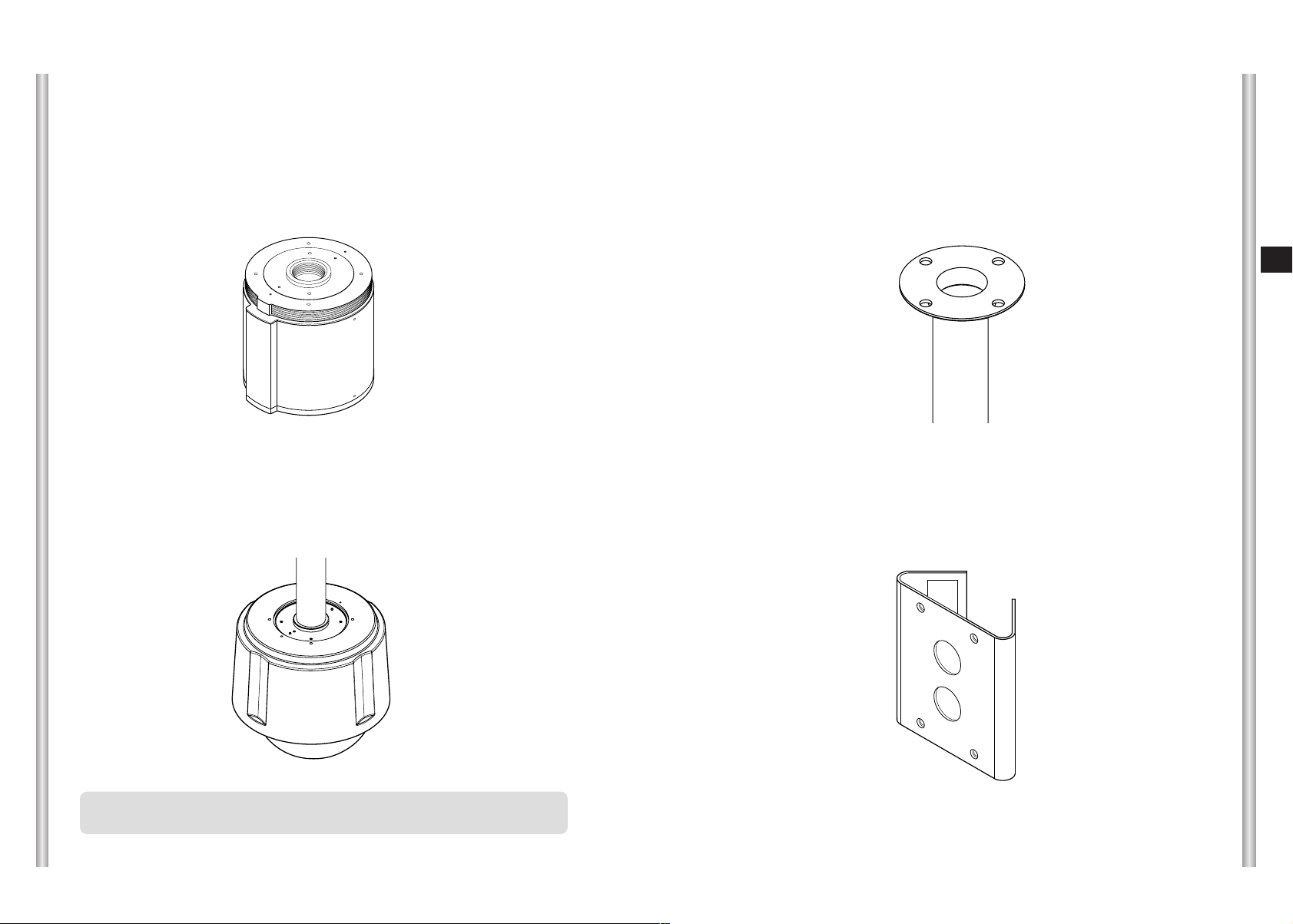
3) INDOOR HOUSING (SHG-120)
This housing is used for installing the SmartDome Camera to an indoor
wall or a ceiling.
5) CEILING MOUNT ADAPTOR (SADT-100CM)
This adaptor is used for installing the indoor housing or the outdoor
housing for the SmartDome Camera to a concrete ceiling.
E
4) OUTDOOR HOUSING (SHG-220)
This housing is used for installing the SmartDome Camera to an
outdoor wall or a ceiling.
❈
To install and use OUTDOOR HOUSING, remove the Clear Case
from the Camera body before installation.
2-6
6) POLE MOUNT ADAPTOR (SADT-100PM)
This adaptor is used for installing the WALL MOUNT ADAPTOR
(SADT-100WM) to a pole that is over 8 cm (2.76 in.) in diameter.
2-7
Page 13
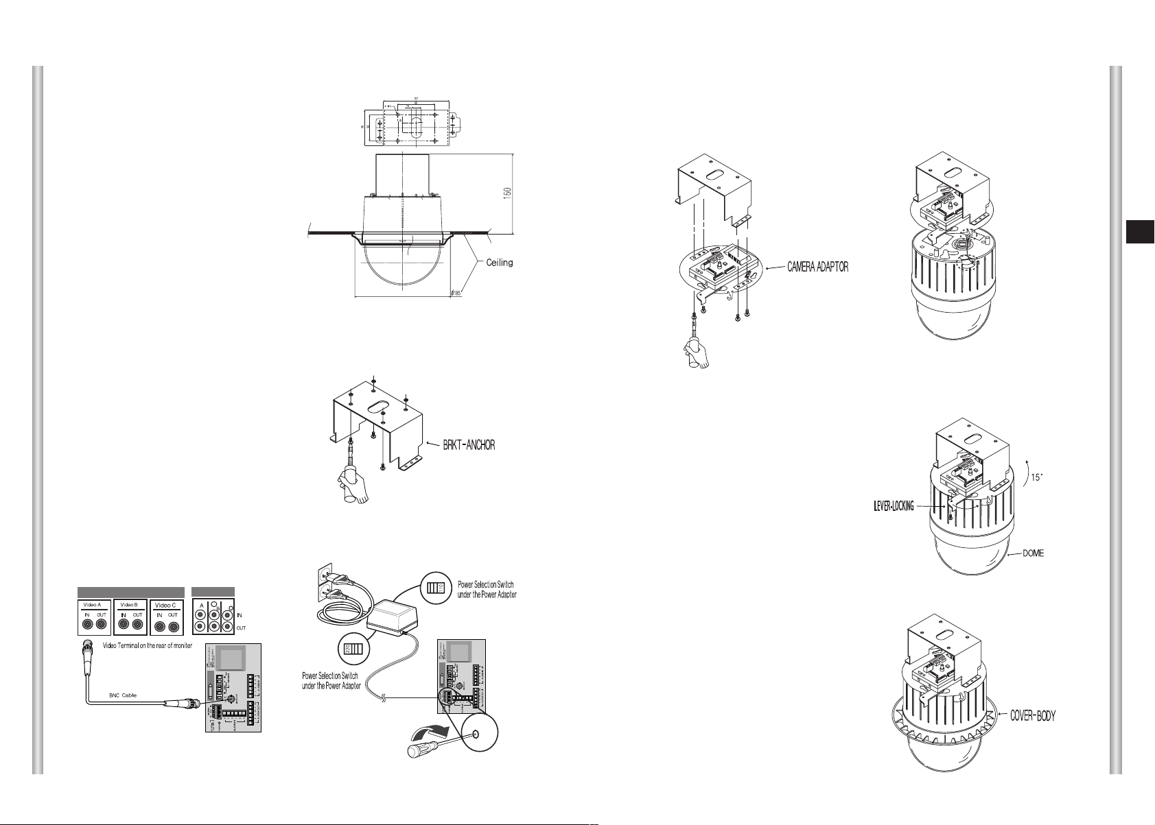
Installing the Camera
1. [Figure 1] Install the structure on the
ceiling.
(Refer to Installation reference
for the Length of the structure)
* Built in by the builder of the structure
5. [Figure 5] Match the
BRKT-ANCHOR and CAMERA
ADAPTER and use 4screws
(PH M4 x 8) to assemble them.
[Figure 5]
6. Pull the safety wire from the case
body, and assembly it to the
camera holder.
[Figure 6]
E
[Figure 1]
Length of
ceiling Hole
2. Make a hole in the ceiling where the camera will be installed.
(The hole should be about ø185)
3. [Figure 2] Assemble the
BRKT-ANCHOR on the ceiling
and screw the 4 bolts in.
[Figure 2]
4. [Figure 3,4] Connect the various cables to the CAMERA ADAPTER.
(See page 2-4)
7. [Figure 7] Match the 3 holes on the
back of the CAMERA and the
CONNECTOR and turn it left about
15 degrees.
(Check the sound of LOCKING
and that the LEVER-LOCKING
is in place)
* Use the screws (BH M3 x L8) to
connect the CAMERA and the
ADAPTER so they don't move.
8. [Figure 8] Assemble the
COVER-BODY onto the DOME.
[Figure 7]
[Figure 8]
2-8
[Figure 3]
[Figure 4]
2-9
Page 14

Chapter 3 Setup Menu Overview
In this chapter, we will look over the Setup Menu of the
SCC-C6407(P), First we'll look over the overall structure of the
Setup Menu, and then we'll look at the functions of each menu.
Structure of the Setup Menu
CAMERA SET CAMERA ID ON.../OFF
V-SYNC INT/LINE...
COLOR/BW COLOR.../BW.../AUTO...
MOTION DET ON.../OFF
ZOOM SPEED 1/2/3/4
DIGITAL ZOOM OFF/X2~X10
EXIT QUIT/SAVE/PRESET
VIDEO SET IRIS ALC.../WDR.../MANU...
SHUTTER OFF/1/100(1/120)~1/1OK/AUTOX2~X160
AGC OFF/LOW/HIGH
MOTION S.SLOW/SLOW/NORM/FAST/F.FAST
WHITE BAL ATW1/ATW2/AWC/MANU...
DIS ON/OFF
FOCUS MODE AF/MF/ONEAF
SPECIAL ...
REVERSE OFF/H/V/H/V
Y-LEVEL (0)l--C-LEVEL (0)l--DETAIL (0)l--RET
EXIT QUIT/SAVE/PRESET
PRESET POSITION SET ...
PRESET ID ON.../OFF
VIDEO SET ON.../OFF
PRESET SPEED 1~8
DWELL TIME 1~60S
IMAGE HOLD ON/OFF
EXIT QUIT/SAVE/DEL
E
3-1
ZONE SET PRIVACY ZONE ...
ZONE DIR SET OFF/ON...
ZONE AREA SET
EXIT QUIT/SAVE
AUTO SET AUTO PAN 1.../2.../3.../4...
PATTERN 1.../2.../3...
SCAN 1.../2.../3.../4...
AUTO PLAY ...
RET
OFF/ON...
3-2
Page 15
ALARM SET ALARM PRIORITY SET ALARM1~8 1~8
EXIT QUIT/SAVE
❈
If the power is turned off after PRESET, AUTO PAN, SCAN,
PATTERN function is activated and no other control is made, camera
will do the same function after the power is turned on.
ALARM IN SET ALARM1~8 NO/NC/OFF
EXIT QUIT/SAVE
ALARM OUT SET ALARM1~8 1~3
MOTION 1~3
EXIT QUIT/SAVE
AUTO SET ALARM1~8
MOTION
OFF/PATTERN1~3/HALF1~2/FULL/SCAN1~4
OFF/PATTERN1~3/HALF1~2/FULL/SCAN1~4
EXIT QUIT/SAVE
AUX OUT CONTROL OUT1 ON/OFF
OUT2 ON/OFF
OUT3 ON/OFF
EXIT QUIT/SAVE
RET
OTHER SET PROPOTIONAL P/T ON/OFF
TURBO P/T ON/OFF
AUTO CAL OFF/6H/12H/18H/24H
D-FLIP ON/OFF
CAM RESET ...
LANGUAGE
ENGLISH/FRANÇAIS/DEUTSCH/ESPAÑOL
PASSWORD ON/OFF
EXIT QUIT/SAVE
SYSTEM INFO
The diagram shown above illustrates the overall structure of the Setup Menu.
In this section, a description of the Setup menu features will enable users of the
SCC-C6407(P) to tailor it to their personal needs.
❈
Menu setting is available only when tilt position is under 90°.
When tilt position is over 90° and menu-on command is received,
pan will automatically rotate 180° and tilt will be move to the
corresponding position.
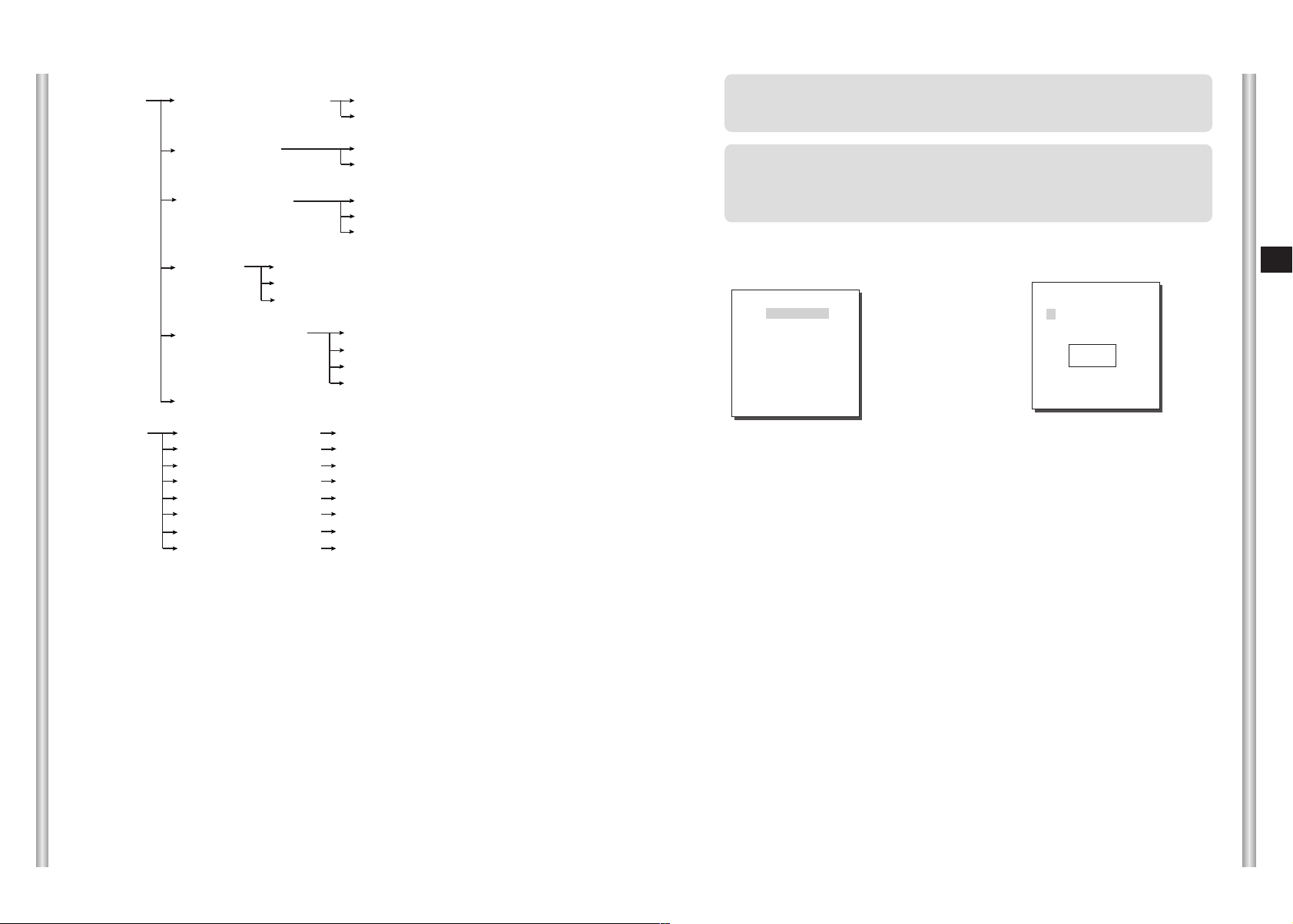
Use the controller to press the MENU selection key and the following
screen will be displayed.
* * MAIN MENU * *
CAMERA SET...
VIDEO SET...
PRESET ...
ZONE SET...
AUTO SET...
ALARM SET...
OTHER SET...
SYSTEM INFO...
PASSWORD
➀
UNDEFINED
In case of
setup. In case of
, use UP/DOWN/LEFT/RIGHT/[ENTER] key for MENU
➀
, type in the 4 digit password first. If correct, the
➁
MENU selection screen like
will be displayed and you will be able to
➀
0 1 2 3 4
5 6 7 8 9
✽ ✽ ✽ ✽
➁ PASSWORD
DEFINED
set up MENU by pressing UP/DOWN/LEFT/RIGHT/[ENTER] key.
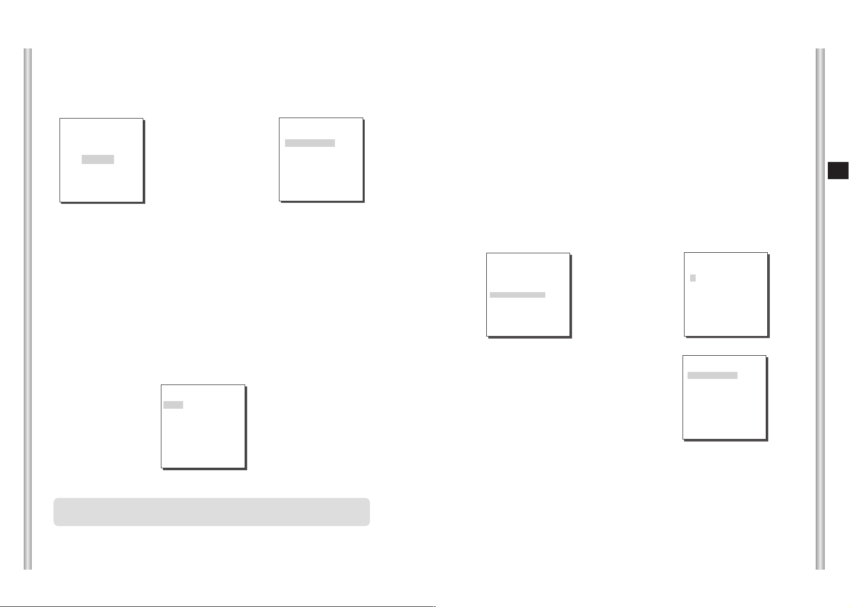
1. CAMERA SET MENU
CAMERA ID
The CAMERA ID menu assigns an ID to the SCC-C6407(P) to be displayed
on the connected monitor.On the CAMERA SET menu screen, select
CAMERA ID to ON and press [Enter]. You will see the sub screen for
deciding on the ID of the SCC-C6407(P). The Camera ID can have up to
20 alphanumeric characters, along with several special characters.
The assigned camera ID may be positioned to any desired location on the
screen by using the LOCATION submenu.
E
3-3 3-4
Page 16

(CAMERA SET)
CAMERA ID ON...
V-SYNC INT
COLOR/BW AUTO...
MOTION DET OFF
ZOOM SPEED 3
DIGITAL ZOOM OFF
EXIT QUIT
➜
Press
[Enter]
(CAMERA ID)
A B C D E F G H I J K L
M N O PQ R S T U V W X
Y Z 0 1 2 3 4 5 6 7 8 9
: ! - + ✽ ( ) /
ï î
SP
SP
LOCATION...
RET
SCC-C6407P........
* " ... " Means there are Sub Menus.
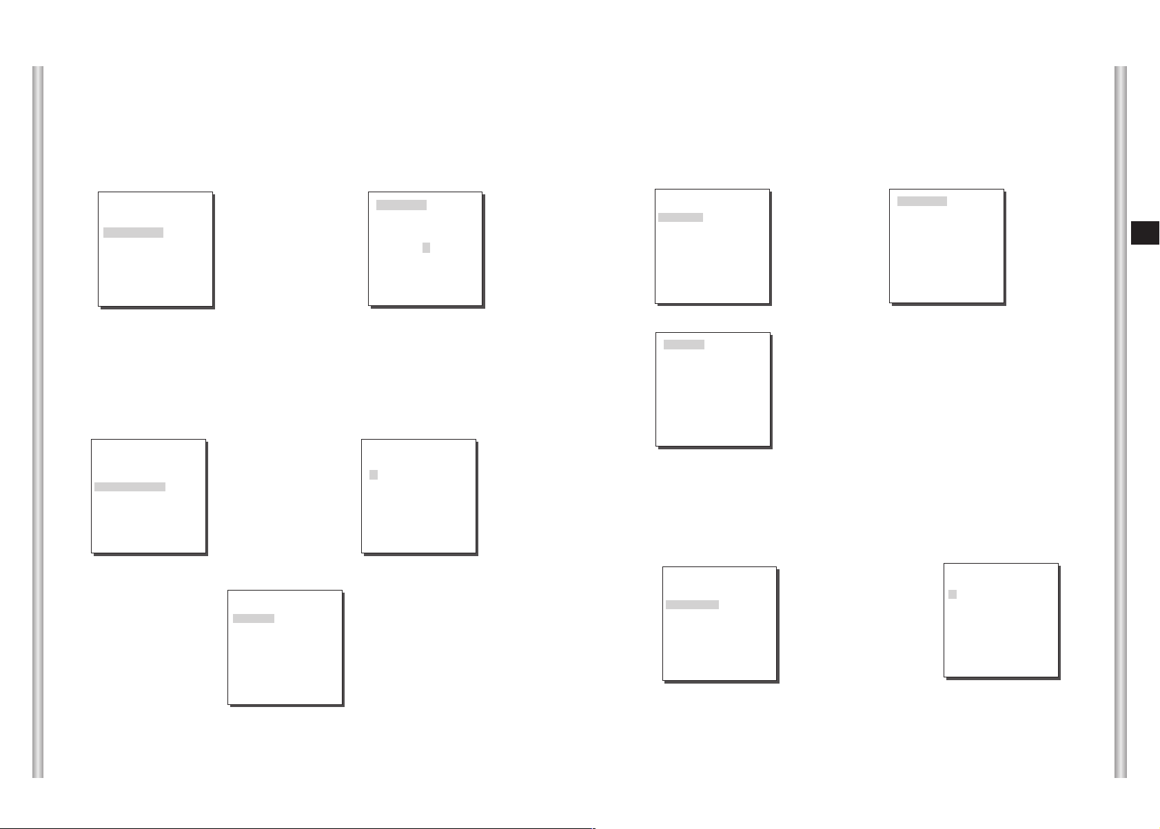
V-SYNC
In the V-SYNC menu, vertical synchronization can be selected. The
vertical synchronization signal supported by the SCC-C6407(P) is the INT
mode made by clock inside the SCC-C6407(P) and LINE mode adjusting
vertical synchronization to the exterior power frequency.
Select LINE and press [Enter]. You will see the LINE LOCK submenu
where you can adjust the phase of the LINE LOCK.
You can use the PHASE menu of the LINE LOCK submenu to assign as
much PHASE as you want.
(CAMERA SET)
CAMERA ID OFF
V-SYNC LINE...
COLOR/BW AUTO...
MOTION DET OFF
ZOOM SPEED 3
DIGITAL ZOOM OFF
EXIT QUIT
➜
Press
[Enter]
(LL-PHASE)
PHASE (-106)I-------RET
COLOR/BW
In the COLOR/BW menu, you can switch ON or OFF the IR (infrared) Filter.
In a poor illumination environment, the IR filter is turned off in the BW mode the its
sensitivity increases as high as a black and white camera. On the other hand, the
IR filter is turned on and the sensitivity decreases in the COLOR mode.
COLOR : The IR Filter is ON and the screen is normal. You can press the
[Enter] key to set the COLOR GAIN LEVEL. And when the AGC
function is on, you can set the AGC COLOER LEVEL.
(CAMERA SET)
CAMERA ID OFF
V-SYNC INT
COLOR/BW COLOR …
MOTION OFF
ZOOM SPEED 0
DIGITAL ZOOM 0
EXIT QUIT
➜
Press
[Enter]
BW : The IR Filter is OFF and the screen is black and white.
(Sensitivity to low light is increased to a level comparable to a black
and white camera.)
Select BW and press [ENTER] and the additional menu to select
BURST ON/OFF will appear.
AUTO : Select to automatically switch between the COLOR mode and BW
mode depending on the amount of light. In low light conditions, the
IR Filter is turned OFF and the sensitivity to low light is increased
by switching to the BW mode, but in bright light conditions, the IR
Filter is turned ON and the sensitivity is decreased by switching to
the COLOR mode.
Select AUTO and press [ENTER] and the additional menu to select
BW LEVEL and DURATION will appear.
- BURST ON : The color burst signal is output together with black and white
composite video signal.
- BURST OFF : The color burst signal is not output.
- LEVEL : You can set the brightness level that changes from COLOR mode
to BW mode in 3 steps : LOW, MEDIUM, and HIGH.
- DURATION : Set the HOLDING time for switching between COLOR and BW
mode depending the changes in the amount of light. You can set
the HOLDING time to 10sec (S), 30sec, 60sec, or 300sec( L).
(COLOR)
GAIN (0)I-------AGC COLOR (0)----I---RET
E
3-5 3-6
Page 17

In AUTO mode, AGC will operates in high speed mode, and you cannot
change it manually, as it is indicated by "---".
(CAMERA SET)
CAMERA ID OFF
V-SYNC INT
COLOR/BW AUTO...
MOTION DET OFF
ZOOM SPEED 0
DIGITAL ZOOM 0
EXIT QUIT
➜
Press
[Enter]
(AUTO)
BURST ON
LEVEL LOW
DURATION S --|---- L
RET
Caution : If you use an infrared light source while in AUTO mode, AUTO
switching malfunction and camera AF malfunction may occur.
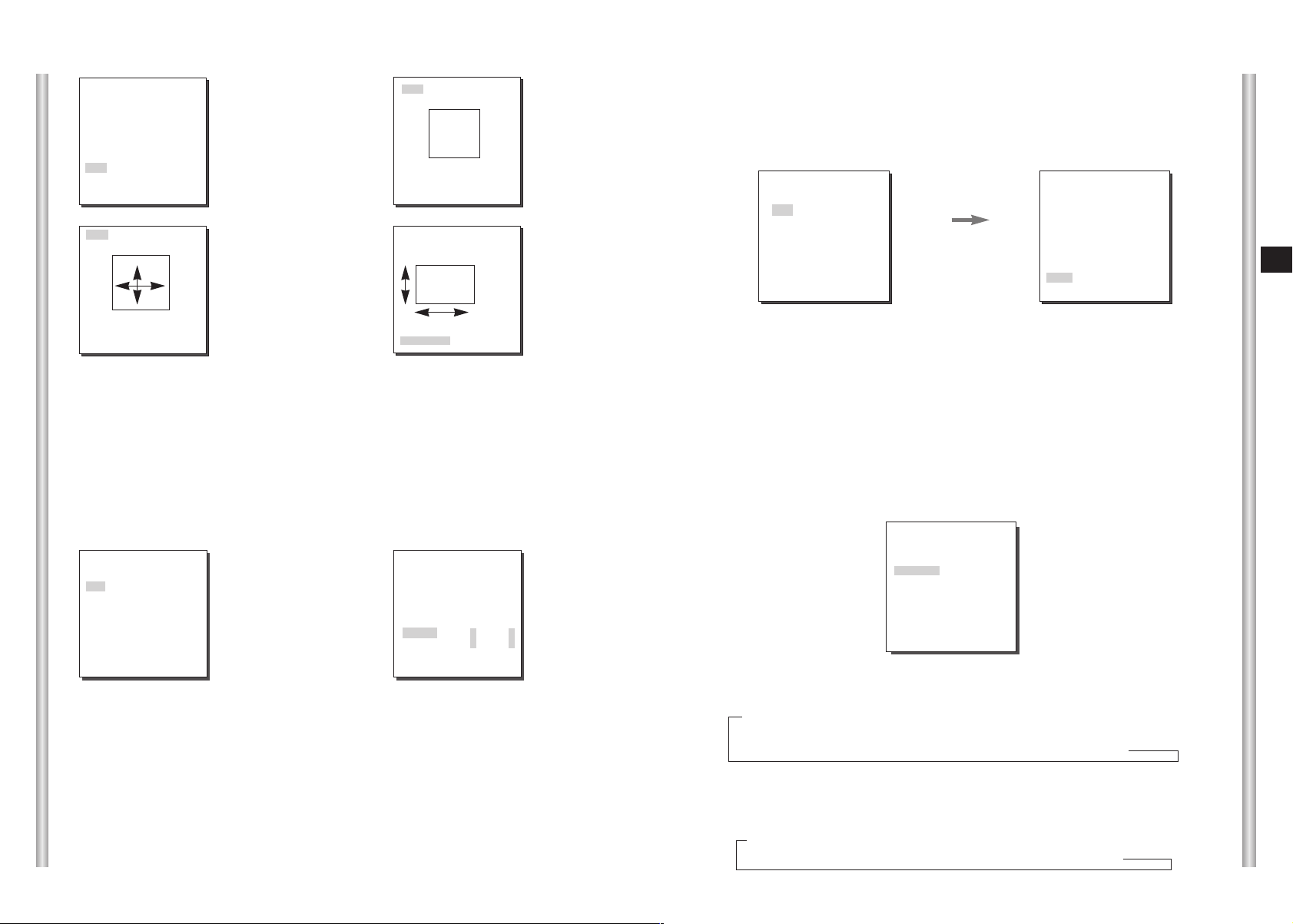
Select ON and press [ENTER] and the MOTION DET additional menu will
appear. The AREA menu, selecting the screen area where the MOTION
detection function will be applied may be selected by PRESET or USER.
Set AREA to PRESET and the MOTION detection function will be applied to
the factory default part.
If you set the AREA menu to USER and press [ENTER], you may vary the size
and position of the area where you want to apply the MOTION detection
function by yourself. Press Left, Right, Up, or Down to select an area size.
Press ENTER and then Left, Right, Up, or Down to select a position. Press
ENTER again to move back to the upper menu.
Use [ENTER] and Left, Right, Up, or Down to move and scale the MOTION
detection area.
Press [ENTER] again and you will escape the AREA setup menu.
Use SENSITIVITY to set up the sensitivity of MOTION detection strength.
The higher, the more sensitive.
E
MOTION DET
In MOTION DET, you can set the Motion Detection function, Motion Detection
Sensitivity, and the Area of Motion Detection. If the Motion Detection function
is set, the movement of an intruder can be detected. When motion is detected,
it sets off the Alarm signal of the Controller.
(CAMERA SET)
CAMERA ID OFF
V-SYNC INT
COLOR/BW COLOR
MOTION DET ON...
ZOOM SPEED 3
DIGITAL ZOOM OFF
EXIT QUIT
➜
Press
[Enter]
(MOTION DET)
AREA PRESET...
SENSITIVITY
RET
L ---|--- H
SIZE
SIZE
➜
Use the [Left,
Right, Up, Down]
Keys
POSITION
❈
After PAN/TILT movement finishes, MOTION DET function will not work
for about 5 seconds to stablize the chage of the screen.
❈
MOTION detection function operates based on the brightness change
within the setup region. Therefore, erroneous operation may occur
depending on the brightness difference between the background and
the object that is being taken, or the status of the area setup, etc.
ZOOM SPEED
In the ZOOM SPEED menu you can select the speed of the ZOOM Key
(Tele/Wide).
Use the [Left] or [Right] keys in the ZOOM SPEED menu to select
the speed.
1 : Magnification x 32 takes about 22 seconds. Slowest speed
2 : Magnification x 32 takes about 10 seconds. Low speed
3 : Magnification x 32 takes about 7 seconds. High speed
4 : Magnification x 32 takes about 5 seconds. Fastest speed
POSITION
3-7
3-8
Page 18

DIGITAL ZOOM
You may set up the digital zoom magnification ratio in the DIGITAL ZOOM
menu. The magnification ratio ranges from OFF to 10. If you set Digital
Zoom of SCC-C6407(P) to max. 10 times, the mode will become the 32 time
optical zoom and you will be able to enlarge a subject by max. 320 times.
Use Left or Right to select a magnification ratio in the DIGITAL ZOOM menu.
(CAMERA SET)
CAMERA ID OFF
V-SYNC INT
COLOR/BW BW...
MOTION DET OFF
ZOOM SPEED 3
DIGITAL ZOOM OFF
EXIT QUIT
(CAMERA SET)
CAMERA ID OFF
V-SYNC INT
COLOR/BW BW...
MOTION DET OFF
ZOOM SPEED 3
DIGITAL ZOOM X10
EXIT QUIT
EXIT
The EXIT menu is used to quit the CAMERA SET menu of the
SCC-C6407(P) and return to the MAIN MENU.
- QUIT : Ignores the changed information and restores the saved
information.
- SAVE : Saves the information of the setting condition of the menu.
- PRESET : Ignores the changed information and restores the initial
factory defaults of the menu.
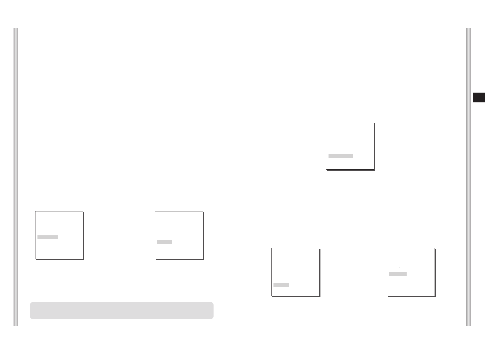
BLC (Submenu of the ALC menu)
If you use a general camera to photograph a subject under backlight or
bright illumination, the subject will be shown dark on the monitor due to
the backlight. BLC(Back Light Compensation) is used to prevent such a
backlight problem to secure distinct images under bright illumination.
Using the [Left, Right] keys, you can set up BOTTOM…, TOP…, LEFT…,
RIGHT…, CENTER… 5 preset areas and the USER…function that can
directly set the areas. For example, for the items in the BLC menu, you
can confirm the preset BOTTOM area by pressing [ENTER] key in the
BOTTOM… status.
(VIDEO SET)
IRIS ALC..
SHUTTER X4
MOTION NORM
WHITE BAL ATW1
DIS OFF
FOCUS MODE ONEAF
SPECIAL ...
EXIT QUIT
(ALC)
➜
Press
[Enter]
(ALC)
BLC OFF
LEVEL (0)--- -I---RET
➜
Press
[Enter]
BLC BOTTOM...
LEVEL (0)----I---RET
E
2. VIDEO SET MENU
IRIS
There is a function to automatically adjust IRIS to the incoming light level.
Owing to this function, you may set up the brightness level yourself.
The ALC(Auto Light Control) menu allows you for video output level setup.
The WDR(Wide Dynamic Range) menu allows you to set up the WDR
level and the FLICKERLESS function.
ALC
Choose the ALC of the IRIS item and press [ENTER] and set he submenu
to the Video Output level and BLC will be shown.The Video Output Level
can be set in the level item using the [Left, Right] keys.
3-9
For items in the BLC menu, the user can set the size and location of the
BLC area by pressing [ENTER] key after put the cursor on USER… using
the [Left, Right] key. For SIZE items, you can use the [Up, Down, Left,
Right] key to designate the SIZE, and then press the [ENTER] key.
You can set the location for areas using the [Up, Down, Left, Right] key in
the LOCATION.
3-10
Page 19
(ALC)
BLC USER...
LEVEL (0) ----I---RET
SIZE
➜
Press
[Enter]
➜
Press
[Enter]
SIZE
LOCATION
SIZE
MANU
When you press [ENTER] key after selecting MANU in the IRIS item, an
additional screen appears in which you can set manually opening or closing
the IRIS.
(VIDEO SET)
IRIS MANU...
SHUTTER OFF
AGC OFF
WHITE BAL ATW1
DIS OFF
FOCUS MODE AF
SPECIAL ...
EXIT QUIT
Press the
ENTER
button.
(MANUAL)
LEVEL (00) ----I---RET
E
LOCATION
LOCATION
Use [Left, Right] key in the LEVEL menu to control the video output
level(brightness).
WDR
The WDR camera is a state-of-art technology to expand the screen profit,
mostly effective when you photograph both indoor and outdoor. In short,
this function provides you with the distinct reproduction of not only the
indoor but also the outdoor. Press [ENTER] to set up the WDR level and
the FLICKERLESS function.
(VIDEO SET)
IRIS WDR...
SHUTTER
AGC
WHITE BAL ATW1
DIS ON
FOCUS MODE AF
SPECIAL ...
EXIT QUIT
OFF
OFF
➜
Press
[Enter]
- LEVEL 1 : Controls the shutter speed while WDR operates.
- LEVEL 2 : Controls the whole brightness while WDR operates.
- FLIKERLESS : This is for preventing flicker on the screen when NTSC
system is used in 50HZ power supply region and PAL system is used in
60HZ power supply region. That is to prevent shaking on the screen
resulted from the discordance of the vertical sync frequency and the
flicker frequency of the illumination. While this menu is ON, the
electronic shutter is fixed to 1/100sec (NTSC) or 1/120 sec (PAL).
3-11
(WDR)
LEVEL1 L----I ----H
LEVEL2 L----I ----H
FLICKERLESS OFF
RET
SHUTTER
You may designate both the fast electronic shutter speed and low
electronic shutter speed in the SHUTTER menu. The fast electronic
shutter supports 7 shutter speeds from 1/100(1/120) to 1/10K second to
be used for the bright and fast video image. The AUTO slow electronic
shutter supports 10 shutter speeds from x2 to x160 and sets the shutter
speed to be slow In order to make the image on the screen more distinct
and brighter when you photograph under dark illumination. If you want to
sense the light brightness to control the shutter speed to the brightness
automatically, select the AUTO slow shutter.
(VIDEO SET)
IRIS ALC...
SHUTTER OFF
AGC
WHITE BAL ATW1
DIS OFF
FOCUS MODE AF
SPECIAL ...
EXIT QUIT
Keep pressing both Left and Right in the SHUTTER menu, the speed will
change in the following sequence.
➝ OFF ➝ AUTO X2 ➝ AUTO X4 ➝ AUTO X6 ➝ AUTO X8 ➝ AUTO X12 ➝
AUTOX16 ➝ AUTO X20 ➝ AUTO X40 ➝ AUTO X80 ➝ AUTO X160 ➝ OFF ➝
1/100(1/120) ➝ 1/250 ➝ 1/500 ➝ 1/1000 ➝ 1/2000 ➝ 1/4000 ➝ 1/10K
❈ In case the IRIS mode is set to WDR, only the following modes are
available.
➝ OFF ➝ AUTO X2 ➝ AUTO X4 ➝ AUTO X6 ➝ AUTO X8 ➝ AUTO X12 ➝
AUTOX16 ➝ AUTO X20 ➝ AUTO X40 ➝ AUTO X80 ➝ AUTO X160
OFF
3-12
Page 20

AGC
The AGC menu was designed to provide you with brighter screen
supposed you photographed any subject in the dark resulting in less
brighter image than regulated. AGC menu setup is available only when
the SHUTTER menu is set to Fast Shutter or Off. Press either Left and
Right to go to LOW or HIGH and the AGC function will be activated. LOW
is use to lower the maximum AGC GAIN and HIGH raise the maximum
AGC GAIN.
When the COLOR/BW menu of the camera set is set to AUTO, the AGC
menu item is left dotted and the maximum AGC GAIN is fixed to HIGH.
(VIDEO SET)
IRIS ALC...
SHUTTER OFF
AGC
WHITE BAL ATW1
DIS OFF
FOCUS MODE AF
SPECIAL ...
EXIT QUIT
LOW
WHITE BAL
Lights are generally denoted as color temperatures and expressed in
Kelvin (
The general light color temperatures are shown below.
10000K
9000K
8000K
7000K
6000K
K
) units.
Blue sky
Rainy
Cloudy
Partly Cloudy
E
MOTION
The MOTION function is available only when the SHUTTER men is set to
Slow Shutter AUTO, being composed of 5 steps, S.SLOW, SLOW,
NORM, FAST, F.FAST.
● S.SLOW reduces the amount of AGC as much as possible to monitor
subjects with no immobility in the dark.
● SLOW reduces the amount of AGC to monitor subjects with little
immobility in the dark.
● NORM sets the amount of AGC to the middle to monitor mobile subjects
in the dark.
● FAST raises the amount of AGC to monitor fast subjects in the dark.
● F.FAST reduces the amount of AGC as much as possible to monitor
very fast subjects in the dark.
When the SHUTTER menu is set to AUTO, press Down to locate the
cursor in the MOTION menu and press Left and Right for MOTION
function setup. Press Left to the SLOW side and Right to the FAST side.
(VIDEO SET)
IRIS ALC...
SHUTTER AUTO x2
MOTION
WHITE BAL ATW1
DIS OFF
FOCUS MODE AF
SPECIAL ...
EXIT QUIT
F.FAST
5000K
4000K
3000K
2000K
1000K
Sunny
Fluorescent lamp
Halogen lamp
Tungsten lamp
Candlelight
3-13
3-14
Page 21
You can select one of four modes for white balance adjustment as follows:
- ATW1/ATW2(Auto-Tracing White Balance Mode): In these modes, the
color temperature is monitored continuously and thereby white balance is
set automatically. The following are the approximate supported color
temperature ranges in these modes.
ATW1 : 2500K ~ 9300K(
ATW2 : 2000K ~ 10000K(Mode recommended for sodium lighting)(
✻
1. If the color temperature is out of this range in ATW1 mode, proper
✻
1)
✻
white balance may not be obtained. In that case, select ATW2 mode.
✻
2. In ATW2 mode, if one color is dominated in the shooted area, the
color can be displayed differently.
Therefore, select the mode which is appropriate for the environment.
- AWC(Auto-Tracing White Balance Control): In this mode, accurate white
balance is obtained by pressing [ENTER] while having a white paper in
front of the camera. White Balance data will be maintained after set it
once. AWC mode is best in locations where the color temperature of light
source is constant.
- MANU : If WHITE BAL menu is set to MANU mode, the user can set the
white Balance considering the current illumination. Select MANU item
and press [ENTER], the sub screen where you can select Manual White
Balance will be shown. Use the left/right keys to select 3200K, 5600K or
OFF(USER) mode in the PRESET menu.
- 3200
K
- 5600
: Set color temperature to 3200
: Set color temperature to 5600
K
K
K
- USER : Choose out a proper value from the RED and BLUE graph for
color and temperature setup.
(VIDEO SET)
IRIS ALC...
SHUTTER
AGC
WHITE BAL MANU...
DIS ON
FOCUS MODE AF
SPECIAL ...
EXIT QUIT
OFF
ON
➜
Press
[Enter]
(AWB/MANUAL)
PRESET 3200K
RET
DIS
The DIS(Digital Image Stabilization) function compensates the camera
screen shaking incurred from vibration.
2)
FOCUS MODE
In the FOCUS MODE MENU, the Focus method can be set to AF, MF, or ONEAF.
- AF : With AUTO FOCUS MODE, you can monitor the screen continuously
and it will focus automatically. While moving the zoom keys, it will
automatically focus so FOCUS key input is not necessary.
- MF : In MANUAL FOCUS MODE the user adjusts the Focus manually.
- ONEAF : The ONEAF Mode performs Auto-focusing only when the SCC-C6407(P)
stops after moving and when the SCC-C6407(P) is not moving it is same
as MF mode.
❈
When in the MF/ONEAF Mode, press the NEAR and FAR keys on the
Controller (SSC-1000) at the same time to perform AUTO FOCUS.)
Use the left/right keys to select AF, MF or ONEAF in the FOCUS MODE menu.
(VIDEO SET)
IRIS ALC...
SHUTTER
AGC
WHITE BAL ATW1
DIS OFF
FOCUS MODE AF
SPECIAL ...
EXIT QUIT
SPECIAL
In SPECIAL menu, you can directly adjust REVERSE, Y-LEVEL, C-LEVEL,
and DETAIL functions.
- REVERSE : Mirrors the screen horizontally, vertically, or in all directions.
- Y-LEVEL : It is used to set the levels for the Sync signal and the entire
brightness signal of the video signal.
- C-LEVEL : It is used to set the levels for the Burst signal and the entire colour
signal of the video signal.
- DETAIL : Controls both horizontal and vertical distinction.
(VIDEO SET)
IRIS ALC...
SHUTTER OFF
AGC ON
WHITE BAL ATW1
DIS ON
FOCUS MODE AF
SPECIAL ...
EXIT QUIT
➜
Press
[Enter]
OFF
OFF
(SPECIAL)
REVERSE OFF
Y-LEVEL (0)I-------C-LEVEL (0)I-------DETAIL (0)--IRET
E
3-15
It is recommended to deactivate the DIS function in the no vibration
environment.
EXIT
It's the same as the EXIT function of the CAMERA SET menu.
3-16
Page 22

3. PRESET
This is the menu that user sets the PAN/TILT location, Zoom/Focus, and
screen condition, so the camera can monitor the presetting area on
demand. A total of 128 presets are available.
* * MAIN MENU * *
CAMERA SET...
VIDEO SET...
PRESET ...
ZONE SET...
AUTO SET...
ALARM SET...
OTHER SET...
SYSTEM INFO...
➜
Press
[Enter]
➜
Press
[Enter]
❈
Set the PRESET position at the TILT which ranges from 0° to 90°. Beyond
this range, PRESET setup is not available.
❈
When you try to set the Preset position by using the Controller(SSC-1000
or SSC-2000) beyound the range of TILT 90°, the text, “SET AGAIN” will
be displayed. In such a case, please retry in the area below TILT 90°.
(PRESET MAP)
0 1 2 3 4
5 6 7 8 9
10 11 12 13 14
15 16 17 18 19
20 21 22 23 24
25 26 27 28 29
30 31
î ï
ID:PRESET 0
PRESET NO.0
POSITION SET ...
PRESET ID ON...
VIDEO SET OFF
PRESET SPEED 8
DWELL TIME 3S
IMAGE HOLD OFF
EXIT QUIT
RET
POSITION SET
From "POSITION SET..." press [ENTER] to get into the PAN/TILT,
FOCUS/ZOOM SET screen
to set the PAN/TILT location and FOCUS/ZOOM condition then press
[ENTER] to return to a higher menu.
PRESET ID
This is the ID set up function for each PRESET.
It can be set up to 12 characters using the left, right, up, and down keys.
The ID location can be set in the submenu of "LOCATION..."
E
VIDEO SET
This is the screen setting function for each PRESET.
Refer to the explanation under "VIDEO SET menu".
PRESET SPEED
This function sets up the speed of PAN or TILT by 8 steps from 1(SLOW)
to 8(FAST).
- PRESET SPEED 1 : Maximum PAN moving speed of 240°/sec
- PRESET SPEED 8 : Maximum PAN moving speed of 400°/sec
DWELL TIME
This is a function setting for the DWELL TIME of the PRESET location in
"SCAN" motion. It can set DWELL TIME From 1 ~ 60 Sec.
IMAGE HOLD
Pauses the image when PRESET is in movement, If you set the IMAGE
HOLD menu to ON, the screen will be paused until PRESET finishes
moving.
EXIT
"QUIT" : Does not save the selected information and returns to a higher
menu.
"SAVE" : Do saves the selected information and returns to a higher menu.
"DEL" : Deletes the selected information and restores the DEFAULT.
Then returns to a higher menu.
3-17
3-18
Page 23
4. ZONE SET
The ZONE SET menu includes the setup of PRIVACY ZONE, ZONE
DIRECTION, and ZONE AREA.
BLANK ALL ABOVE
The available angle for setup ranges from OFF/0/-10 to -90 and the area
above a set angle will be regarded as the ZONE area.
* * MAIN MENU * *
CAMERA SET...
VIDEO SET...
PRESET...
ZONE SET...
AUTO SET...
ALARM SET...
OTHER SET...
SYSTEM INFO...
➜
Press
[Enter]
(ZONE SET)
PRIVACY ZONE ...
ZONE DIR SET ON...
ZONE AREA SET OFF
EXIT QUIT
PRIVACY ZONE
Move PAN/TILT/ZOOM to select an area that can infringe someone
privacy, then this function will hide the area if it can be involved in the
photograph to protect his privacy. The number of area reaches up to 12.
STYLE
In the STYLE menu, you may the shape of the PRIVACY ZONE area on the
screen.
- MOSAIC1 : The privacy zone is displayed with the mosaic of 16 X 16 pixel.
- MOSAIC2 : The privacy zone is displayed with the mosaic of 32 X 32 pixel.
(PRIVACY ZONE SET)
STYLE MOSAIC1
BLANK ALL ABOVE OFF
BLANK ALL BELOW OFF
PRIVACY ZONE MAP ON...
BLANK ALL BELOW
The available angle for setup ranges from OFF/0/-10 to -90 and the area
below a set angle will be regarded as the ZONE area.
PRIVACY ZONE MAP
Press [ENTER] to enter the PRIVACY ZONE MAP screen from
“PRIVACY ZONE MAP ON..”.
Select a privacy zone number and press [ENTER] from the PRIVACY
ZONE MAP screen to enter the PRIVACY ZONE setup screen.
(PRIVACY ZONE SET)
STYLE
BLANK ALL ABOVE OFF
BLAK ALL BELOW OFF
PRIVACY ZONE MAP ON...
EXIT QUIT
MOSAIC1
➜
Press
[Enter]
➜
Press
[Enter]
(PRIVACY ZONE MAP)
0 1 2 3 4 5
6 7 8 9 10 11
RET
PRIVACY ZONE SET 0
SET ZONE AREA ON...
SET ZOOM ...
REVERSE ON
EXIT QUIT
E
3-19
EXIT QUIT
❈
Set to the PRIVACY ZONE section, the mosaic screen will not be
recovered after recording.
3-20
Page 24

SET ZONE AREA
Press [ENTER] at the “SET ZONE AREA...” position to enter the
PRIVACY ZONE setup screen. Control PAN/TILT/ZOOM to select 4
apexes of the PRIVACY ZONE area and the rectangular PRIVACY
ZONE area will be completed.
SET ZOOM
Press [ENTER] at the “SET ZOOM...” position to enter the ZOOM setup
screen. After ZOOM setup, the PRIVACY ZONE function will be in action
only at the higher magnification than the Zoom magnification
as set.
PRIVACY ZONE SET 0
SET ZONE AREA ON...
SET ZOOM ...
REVERSE OFF
EXIT QUIT
PRIVACY ZONE P/T 2
➜
Press
[Enter]
PRIVACY ZONE P/T 1
●
control, press
PRIVACY ZONE P/T 3
➜
●
After P/T/Z
control, press
[ENTER]
PRIVACY ZONE P/T 4
●
➜
After P/T/Z
control, press
[ENTER]
❈
For the safer privacy protection, select about 10 % more than the
actual size to hide when you set up the PRIVACY ZONE area.
●
➜
After P/T/Z
[ENTER]
PRIVACY ZONE SET 0
SET ZONE AREA ON...
SET ZOOM ...
REVERSE OFF
EXIT QUIT
➜
Press
[Enter]
SET ZOOM
REVERSE
The REVERSE function applies PRIVACY MASK to the other area than
set as a privacy zone. ON/OFF is available.
PRIVACY ZONE SET 0
SET ZONE AREA ON...
SET ZOOM ...
REVERSE ON
EXIT QUIT
EXIT
"QUIT" : Does not save the selected information and returns to a higher
menu.
"SAVE" : Do saves the selected information and returns to a higher menu.
"DEL" : Deletes the selected information and restores the DEFAULT.
Then returns to a higher menu.
E
3-21
❈
4 points of PRIVACY ZONE area are in the middle of the screen.
Therefore, when the tilt is positioned at upside limit(0° or 180°),
PRIVACY ZONE cannot be set in the area which is displayed
above center.
❈
If the points becomes X shape, it means PRIVACY ZONE cannot
be set due to the size limitation.
ZONE DIR SET/ZONE AREA SET
This function indicates the ID or direction depending on the set value
when PAN of SCC-C6407(P) is located in a specific area. If set to AREA,
it indicates the ID of the selected area and if set to N(NORTH), NE(NORTH-
EAST), E(EAST), SE(SOUTH-EAST), S(SOUTH), SW(SOUTH-WEST), W(WEST),
NW(NORTH-WEST.
3-22
Page 25
ZONE DIR SET
Press the [Enter] key in the “ZONE DIR SET ON…” mode to enter the
NORTH SET screen. MAP. Move PAN to set the NORTH position and
press [ENTER]. Based on the North position,the direction of N(North),
NE(North-East), E(East), SE(South-East), S(South), SW(South-West),
W(West), NW(North-West) is displayed whenever you move PAN.
LOCATION
The “LOCATION...” menu designates the left/right LIMIT positions of
ZONE AREA. Enter the setup screen to move PAN, then select a start
position and press [ENTER]. Move PAN again
to select a end position and press [ENTER]. Now, ZONE AREA setup is
complete.
(ZONE SET)
PRIVACY ZONE ...
ZONE DIR SET ON...
ZONE AREA SET OFF
➜
Press
NORTH SET
N
[Enter]
EXIT QUIT
ZONE AREA
Press [ENTER] to enter the ZONE AREA MAP screen from “ZONE
AREA SET...”. Select a ZONE AREA number from the ZONE AREA MAP
screen and press [ENTER] to enter the ZONE AREA setup screen.
(ZONE SET)
PRIVACY ZONE ...
ZONE DIR SET OFF
ZONE AREA SET ON...
EXIT QUIT
➜
Press
[Enter]
➜
Press
[Enter]
ZONE AREA SET 0
LOCATION ...
ZONE ID SET ...
ZONE ENABLE ON
EXIT QUIT
(ZONE AREA MAP)
0 *1 2 3
4 5 6 7
RET
ZONE AREA SET 0
LOCATION ...
ZONE ID SET ...
ZONE ENABLE ON
EXIT QUIT
SET END!
➜
Press
[Enter]
SET START!
➜
After P/R/Z
control, press
[ENTER]
After PAN control,
press [ENTER] to
finish.
ZONE ID SET
This function is used to allocate as many as 12 IDs to each zone area.
Use Left , Right, UP, or DOWN for this purpose. You may select the ID
position from the additional menu of “LOCATION...”.
ZONE AREA SET 0
LOCATION ...
ZONE ID SET ...
ZONE ENABLE ON
EXIT QUIT
➜
Press
[Enter]
ZONE AREA ID 0
A B C D E F G H I J K L
M N O P Q R S T U V W X
Y Z 0 1 2 3 4 5 6 7 8 9
: ! - + ✽ ( ) /
ï î
SP
LOCATION...
RET
ZONE 0........
SP
E
3-23
ZONE ENABLE
This function turns on or off the ZONE AREA ID indication.
3-24
Page 26

5. AUTO SET
The AUTO SET menu includes AUTO PAN, PATTERN, and SCAN and it
is able to set up the AUTO PLAY motion.
AUTO PAN
After selecting the locations of two points (PAN/TILT) of START and END,
it loops continuously in the set up SPEED. The number of AUTO PAN is
up to 4.
* * MAIN MENU * *
CAMERA SET...
VIDEO SET...
PRESET...
ZONE SET...
AUTO SET...
ALARM SET...
OTHER SET...
SYSTEM INFO...
➜
Press
[Enter]
➜
Press
[Enter]
(AUTO SET)
AUTO PAN 1...
PATTERN 1...
SCAN 1...
AUTO PLAY ...
RET
AUTO PAN 1
POSITION SET ...
DIRECTION RIGHT
ENDLESS ON
SPEED 32
DWELL TIME 3S
EXIT QUIT
DIRECTION
This sets up the movement direction of the START to END location
(PAN location standard)
"RIGHT " : "LEFT " :
E
ENDLESS
This is a 360-degree rotation function that stops for the DWELL TIME only in the
START and END positions without running between the START and END
positions. It can be set to "ON" or "OFF".
SPEED
This is a setting function for movement speed setup. It can be set from
STEP1 to STEP64.
DWELL TIME
This is a function for setting up the time to stay in the START to END position.
PATTERN
This is a replay function so that the MANUAL functions such as PAN, TILT,
ZOOM, and FOCUS are played for 2 minutes.
POSITION SET
The menu “POSITION SET …” sets the Start / End position of AUTO PAN.
Return to the settings screen and set the desired START position for
PAN/TILT, and then press the [ENTER] key. And, set the END position for
the PAN/TILT. Press the [ENTER] key to finish the setup for AUTO PAN
Start/End positions.
3-25
❈ When the PATTERN is saved/executed, the PAN/TILT is operated with
PROPORTIONAL ON, TURBO OFF.
❈ If the SSC-1000 or SSC-2000 is used when uploading/downloading the
menu setup, reset the PATTERN because it may be different with the first
setting.
3-26
Page 27

* * MAIN MENU * *
CAMERA SET...
VIDEO SET...
PRESET...
ZONE SET...
AUTO SET...
ALARM SET...
OTHER SET...
SYSTEM INFO...
PATTERN SET 1
SET START POSITION
AND ENTER
➜
Press
[Enter]
➜
After PATTER
START
position setup,
press
[ENTER].
(AUTO SET)
AUTO PAN 1...
PATTERN 1...
SCAN 1...
AUTO PLAY ...
RET
PATTERN SET 1
➜
Press
[Enter]
AUTO PLAY
AUTO PLAY executes SCAN, AUTO PAN, PATTERN, and PRESET when there
is no camera action after AUTO RETURN finishes.
(AUTO SET)
AUTO PAN 1...
PATTERN 1...
SCAN 1...
AUTO PLAY ...
RET
➜
Press
[Enter]
(AUTO PLAY SET)
AUTO RETURN 12H
AUTO PLAY SCAN
PLAY NUMBER 1
QUIT
E
PATTERN can be set upto 3. Choose 1, 2, or 3 with the left or right key in the
"PATTERN SET" and press [ENTER] to get into the PATTERN set up screen. From
the moment "PATTERN 1 SET" is gone for 2 minutes, it memorizes the MANUAL
movements and after 2 minutes it will return to a higher menu. If you want to finish
set up before the 2-minutes ends, press [ENTER].
SCAN
SCAN sets the direction of PRESET movement during “SCAN” operation. The
number of SCAN is up to 4 and each SCAN is able to allocate 32 PRESETs as a
maximum.
(AUTO SET)
AUTO PAN 1...
PATTERN 1...
SCAN 1...
AUTO PLAY ...
RET
➜
Press
[Enter]
If you enter the SCAN SET screen, SCAN MAP will be displayed. Move the cursor
to the number marked * where PRESET is saved and press [ENTER] and
S will appear and a PRESET will be included in SCAN.
(SCAN MAP 1)
0*S 1* 2 3 4
5 6 7 8 9
10 11 12 13 14
15 16 17 18 19
20 21 22 23 24
25 26 27 28 29
30 31
î ï
EXIT SAVE
AUTO RETURN
This menu sets up the time during which AUTO PLAY repeats.
AUTO PLAY
This function sets up the motion which will be repeatedly performed by
SCC-C6407(P) whenever the time set by AUTO RETURN elapses. It covers
SCAN, AUTO PAN, PATTERN, and PRESET setup.
PLAY NUMBER
This menu allocates a number to the motion set by AUTO PLAY. The numbers
range from 1 to 4 for SCAN AND AUTO PAN, 1 to 3 for PATTERN, and 0 to 127
for PRESET.
3-27
3-28
Page 28

6. ALARM SET
It consists of 8 ALARM INPUTs and 3 ALARM OUTs.It can sense an
ALARM input from exterior SENSORs and it performs with PRESET or
PATTERN function and outputs the ALARM OUT signals.
The Alarm will be recognized only when its input lasts more than 150ms
and the alarm operation time depends on the Preset Dwell time
corresponding to the alarm and whether AUTO is involved.
* * MAIN MENU * *
CAMERA SET...
VIDEO SET...
PRESET...
ZONE SET...
AUTO SET...
ALARM SET...
OTHER SET...
SYSTEM INFO...
➜
Press
[Enter]
ALARM PRIORITY SET
This sets the priority of the 8 ALARM inputs so ALARM can work
corresponding to the priority.
The priority of the DEFAULT is ALARM1, ALARM2, ALARM3, ALARM4,
ALARM5, ALARM6, ALARM7, ALARM8.
If the ALARM is working at the same time and the priority is the same, it
will operate according to the DEFAULT priority. While the ALARM is
working, it cannot detect MOTION.
( ALARM SET)
ALARM PRIORITY SET ...
ALARM IN SET..
ALARM OUT SET..
AUTO SET..
AUX OUT CONTROL..
RET
AUTO SET
This menu designates what to do at the time of ALARM input. Once an
alarm is given, the camera will shortly move to the PRESET position
corresponding to the respective alarm as follows.
PRESET1 to ALARM1~8
PRESET9 to MOTION
After DWELL TIME at a PRESET position, PATTERN or SCAN will be in
action according to the AUTO SET setup.
Setup of OFF/1/2/3/HALF1/HALF2/FULL/SCAN1~4 is available.
OFF dues not perform PATTERN or SCAN after moved to PRESET and
each menu has its own function as follows.
PATTERN 1~3 : Preset PATTERN action,
HALF1 : Continuous operation of PATTERN1 + PATTERN2
HALF2 : Continuous operation of PATTERN2 + PATTERN3
FULL : Continuous operation of all the aboves
SCAN 1~4 : Scanning as set
AUX OUT CONTROL
This sets the ALARM OUT motion to continue or act only when the
ALARM is working.
If it is set to OFF the ALARM OUT motion will operate only when the
ALARM is working.
(Active "Low"), and if it's set to ON, the ALARM OUT will always operate
regardless of the ALARM.
E
ALARM IN SET
This sets the input TYPE to "NO" (Normal Open), "NC" (Normal Close), or
"OFF" depending on the features of the SENSOR connected.
ALARM OUT SET
Each ALARM input corresponds to one of the 3 ALARM OUT.
3-29
7. OTHER SET
PROPORTIONAL P/T
This function controls the PAN/TILT speed to the ZOOM magnification
ratio during the manual operation of PAN/TILT. If you set
PROPORTIONAL P/T to ON, the PAN/TILT speed will increase in the
ZOOM WIDE mode and decrease in the ZOON TELE mode even in the
same manual operation.
3-30
Page 29

TURBO P/T
This function doubles up the speed of PAN/TILT movement by manual
operation of PAN/TILT. The speed may go up to 180°/sec(PAN).
AUTO CAL
This function turns on or off Auto Calibration. SCC-C6407(P) has the Auto
Calibration function to improve the precision of LENS and PAN/TILT
motor. You may set to OFF/6H/12H/18H/24H. Without user’s key input for
the time designated by the user, A.C. will appear on the screen while
initializing LENS and PAN/TILT.
D-FLIP
When D-FLIP is off, TILT movement ranges from 0° to 90°.
When D-FLIP is on, TILT movement ranges from 0° to 180°.
When D-FLIP is on, images mirror vertically and horizontally in the area
beyond TILT 90°.
CAM RESET
CAM RESET clears all the settings made so far and restores the factory
default settings.
"CAMERA RESET?" message appears when you select CAM RESET.
Select "CANCEL" to return to the menu setup display or select OK to
restore the factory default settings.
❈ Be careful when performing a CAM RESET operation, as it deletes all
setup values.
LANGUAGE
This function selects a language for MENU setup. Press UP/DOWN key to
choose English, French, German, Spanish, or Italian, and the selected
language will be applied to the full screen.
PASSWORD
This function selects or cancels the MENU setup password. Press
[ENTER] at the state of PASSWORD ON, and the following screen will
appear for password setup.
(OTHER SET)
PROPORTIONAL P/T ON
TURBO P/T OFF
AUTO CAL. OFF
D-FLIP ON
CAM RESET ...
LANGUAGE ENGLISH
PASSWORD ON...
EXIT QUIT
➜
Press
[Enter]
(PASSWORD)
0 1 2 3 4
5 6 7 8 9
✽ ✽ ✽ ✽
✽ ✽ ✽ ✽
RET
Press UP/DOWN/LEFT/RIGHT key to locate the cursor on a number and
press [ENTER] for password setup. After you finish inputting the 4 digits
password and the 2nd row of the 4 digits PASSWORD input screen, input
the selected password again for reassurance.
If correct, the cursor will move to RET.
Press [ENTER] at RET, and the selected password will be saved,
returning to the OTHER SET screen.
Default password is 0123.
8. SYSTEM INFO
This menu allows you to check S/W version, communication protocol,
baud rate, and address of SCC-C6407(P).
* * MAIN MENU * *
CAMERA SET...
VIDEO SET...
PRESET...
ZONE SET...
AUTO SET...
ALARM SET...
OTHER SET...
SYSTEM INFO...
➜
Press
[Enter]
( SYSTEM INFO)
FPGA VER. V1.000
ALARM VER. V1.000
MOTOR VER. V1.000
CAMERA VER. V1.000
EEPROM VER. V1.000
PROTOCOL SAMSUNG
COMM. TYPE
BAUD RATE 38400
ADDRESS 0
SERIAL NO. 000000000000000
RET
RS-485, HALF
E
3-31
3-32
Page 30

9. SHORT KEYS
SSC-1000 or SSC-2000 Controller supports the following short keys.
Function Key
CAMERA SET…
COLOR/BW COLOR
COLOR/BW BW
COLOR/BW AUTO
VIDEO SET…
IRIS WDR
IRIS ALC
FOCUS MODE AF
FOCUS MODE MF
FOUCS MODE ONEAF
ALARM SET…
AUX OUT CONTROL…
OUT1 ON
OUT1 OFF
OUT2 ON
OUT2 OFF
OUT3 ON
OUT3 OFF
OTHER SET…
PROPORTIONAL P/T ON
PROPORTIONAL P/T OFF
TURBO P/T ON
TURBO P/T OFF
D-FLIP ON
D-FLIP OFF
AUTO RETURN *1)
AUTO CAL.
CAM RESET
[PRESET] + [1] + [2] + [8] + [Enter]
[PRESET] + [1] + [2] + [9] + [Enter]
[PRESET] + [1] + [3] + [0] + [Enter]
[PRESET] + [1] + [3] + [1] + [Enter]
[PRESET] + [1] + [3] + [2] + [Enter]
[PRESET] + [1] + [3] + [3] + [Enter]
[PRESET] + [1] + [3] + [4] + [Enter]
[PRESET] + [1] + [3] + [5] + [Enter]
[PRESET] + [1] + [3] + [6] + [Enter]
[PRESET] + [1] + [3] + [7] + [Enter]
[PRESET] + [1] + [3] + [8] + [Enter]
[PRESET] + [1] + [3] + [9] + [Enter]
[PRESET] + [1] + [4] + [0] + [Enter]
[PRESET] + [1] + [4] + [1] + [Enter]
[PRESET] + [1] + [4] + [2] + [Enter]
[PRESET] + [1] + [4] + [3] + [Enter]
[PRESET] + [1] + [4] + [4] + [Enter]
[PRESET] + [1] + [4] + [5] + [Enter]
[PRESET] + [1] + [4] + [6] + [Enter]
[PRESET] + [1] + [4] + [7] + [Enter]
[PRESET] + [1] + [4] + [8] + [Enter]
[PRESET] + [1] + [4] + [9] + [Enter]
[PRESET] + [1] + [5] + [0] + [Enter]
* SCC-C6407(P) has two FANs inside for preventing overheating.
If FAN doesn't work properly, messages below will be displayed.
In those case, replace the FAN.
- CAMERA FAN ERROR !
: This message is displayed when the FAN which is connected with camera of
SCC-C6407(P) does not work properly.
- ALARM FAN ERROR !
: This message is displayed when the FAN which is located bottom of
SCC-C6407(P) does not work properly.
Contact your nearest Samsung Electronics Service Center or designated retailer
before replacing the FAN.
E
Other keys than AUTO CAL. and AUTO RETURN, upon execution, shall
be applied to the MENU setup process.
*1) The use of AUTO RETURN will be available only when the function
equivalent to AUTO PLAY, a sub menu of AUTO SET has been built in.
3-33
3-34
Page 31

Product specifications
SCC-C6407
1
2
3
4
5
6
7
8
9
10
11
12
13
14
15
16
17
18
19
20
21
22
23
24
25
Product Type
Power Input
Power Consumption
Broadcasting Type
Image Device
Effective Pixels
Scanning Mode
Scanning line Frequency
Synchronization Mode
Resolution
Min. Object Illumination
Color Temperature
Signal Output
PAN Function
TILT Function
REMOTE CONTROL
Operation Temperature
Operation Humidity
Lives of Main Parts
Items
S/N Ratio
WDR
Lens
ALARM
SIZE
Weight
Contents
- Zoom lens single body WDR SmartDome CAMERA
- AC 24 ± 10% (60Hz ± 0.3Hz)
- 22W
- NTSC STANDARD COLOR SYSTEM
- 1/4 inch WDR compatible Exview HAD CCD
- 768(H) x 494(V)
- 525 Lines, 2:1 Interlace
- Horizontal : 15, 734 Hz(INT) / 15, 750 Hz(L/L)
- Vertical : 59, 94 Hz(INT) / 60 Hz(L/L)
- INT/LINE LOCK
- 480 TV LINES
- 50dB (AGC OFF)
- COLOR : 0.2 Lux (SENS UP X4)
- B/W : 0.07 Lux (SENS UP X4)
- 128
- ATW1/ATW2/AWC/MANUAL MODE
- COMPOSITE VIDEO OUT : 1.0 Vp-p 75 ohms/BNC
- one body; 32x Zoom lens
- Focal length : 3.55 to 113 mm
- Aperture : F1.69(Wide), F4.17(Tele)
- Auto Focus
- PAN range : 360° Endless
- Preset Pan Speed : 400° /sec, maximum
- Manual Pan Speed : 0.1° ~ 180° /sec (64Step)
- TILT range : 0° ~ 180°
- Preset Tilt Speed : 200° /sec, maximum
- Manual Tilt Speed : 0.1° ~ 90° /sec (64Step)
- Tele/Wide(ZOOM), NEAR/FAR(FOCUS),
- Alarm Inputs : 8 IN(5mA Sink)
- Alarm Outputs : 3 OUT (Open collector : 2
- -10°C ~ +50°C
- ~90%
- DOME : 147 (ø),
- Outline : 159.6(ø) x 177(H)
- 1.7Kg
- Lens
- Slip-ring
- Fan
0.005 Lux (SENS UP X160)
0.002 Lux (SENS UP X160)
(3200K, 5600K, R/B GAIN Court)
Iris Open/Close, Pan/Tilt, MENU
RS-485 HALF/FULL Duplex, RS-422
DC24V 40mA Max, Relay : 1, NO, NC, COM
2A 30VDC, 0.5A 125VAC Max)
RemarkNO
One Year(for
use of Full AF)
Rotated
10,000,000
Times
4.5 Years
SCC-C6407P
1
2
3
4
5
6
7
8
9
10
11
12
13
14
15
16
17
18
19
20
21
22
23
24
25
Product Type
Power Input
Power Consumption
Broadcasting Type
Image Device
Effective Pixels
Scanning Mode
Scanning line Frequency
Synchronization Mode
Resolution
S/N Ratio
Min. Object Illumination
Color Temperature
Signal Output
PAN Function
TILT Function
REMOTE CONTROL
Operation Temperature
Operation Humidity
Lives of Main Parts
Items
WDR
Lens
ALARM
SIZE
Weight
Contents
- Zoom lens single body WDR SmartDome CAMERA
- AC 24 ± 10% (50Hz ± 0.3Hz)
- 22W
- PAL STANDARD COLOR SYSTEM
- 1/4 inch WDR compatible Exview HAD CCD
- 752(H) x 582(V)
- 625 Lines, 2:1 Interlace
- Horizontal : 15, 625Hz(INT) / 15, 625 Hz(L/L)
- Vertical : 50 Hz(INT) / 50 Hz(L/L)
- INT/LINE LOCK
- 480 TV LINES
- 50dB (AGC OFF)
- COLOR : 0.2 Lux (SENS UP X4)
- B/W : 0.07 Lux (SENS UP X4)
- 128
- ATW1/ATW2/AWC/MANUAL MODE
- COMPOSITE VIDEO OUT : 1.0 Vp-p 75 ohms/BNC
- one body; 32x Zoom lens
- Focal length : 3.55 to 113 mm
- Aperture : F1.69(Wide), F4.17(Tele)
- Auto Focus
- PAN range : 360° Endless
- Preset Pan Speed : 400° /sec, maximum
- Manual Pan Speed : 0.1° ~ 180° /sec (64Step)
- TILT range : 0° ~ 180°
- Preset Tilt Speed : 200° /sec, maximum
- Manual Tilt Speed : 0.1° ~ 90° /sec (64Step)
- Tele/Wide(ZOOM), NEAR/FAR(FOCUS),
- Alarm Inputs : 8 IN(5mA Sink)
- Alarm Outputs : 3 OUT (Open collector : 2
- -10°C ~ +50°C
- ~90%
- DOME : 147 (ø),
- Outline : 159.6(ø) x 177(H)
- 1.7Kg
- Lens
- Slip-ring
- Fan
0.005 Lux (SENS UP X160)
0.002 Lux (SENS UP X160)
(3200K, 5600K, R/B GAIN Court)
Iris Open/Close, Pan/Tilt, MENU
RS-485 HALF/FULL Duplex, RS-422
DC24V 40mA Max, Relay : 1, NO, NC, COM
2A 30VDC, 0.5A 125VAC Max)
RemarkNO
One Year(for
use of Full AF)
Rotated
10,000,000
Times
4.5 Years
E
3-35
3-36
Page 32

Cautions
• The copyright of the manual belongs to Samsung Electronics Co., Ltd.
Without the permission of Samsung Electronics it cannot be reproduced
•
electronically, mechanically, audibly, or by any other method.
•
This manual will be modified according to product enhancements.
Correct Disposal of This Product
(Waste Electrical & Electronic Equipment)
(Applicable in the European Union and other European countries with
separate collection systems)
This marking shown on the product or its literature, indicates that it should not be
disposed with other household wastes at the end of its working life. To prevent
possible harm to the environment or human health from uncontrolled waste
disposal, please separate this from other types of wastes and recycle it responsibly
to promote the sustainable reuse of material resources.
Household users should contact either the retailer where they purchased this
product, or their local government office, for details of where and how they can take
this item for environmentally safe recycling.
Business users should contact their supplier and check the terms and conditions of
the purchase contract. This product should not be mixed with other commercial
wastes for disposal.
Page 33

SmartDome Camera
SCC-C6407(P)
Benutzerhandbuch
D
Page 34

Sicherheitshinweise
Ziel dieser Informationen ist es, den ordnungsgemäßen Gebrauch dieses
Geräts sicherzustellen und dadurch Gefahren oder Sachbeschädigungen zu
vermeiden. Bitte befolgen Sie alle Anweisungen.
* Die Sicherheitshinweise sind mit “Warnung” und “Achtung”
gekennzeichnet, wie nachfolgend angegeben:
Warnung: Die Nichtbeachtung eines Warnhinweises kann zum Tode oder
zu schweren Verletzungen führen.
Achtung: Die Nichtbeachtung eines mit Achtung gekennzeichneten
Hinweises kann zu Verletzungen und Sachschaden führen.
Die mit Warnung gekennzeichneten
Informationen weisen auf eine mögliche
Gefahr hin, die zum Tode oder zu
schweren Verletzungen führen kann.
Die mit Achtung gekennzeichneten
Informationen weisen auf eine mögliche
Gefahr hin, die zu Verletzungen oder
Sachschaden führen kann.
Warnung
6. Platzieren Sie keine leitfähigen Gegenstände (wie z. B. Schraubenzieher,
Münzen und metallene Objekte) oder mit Wasser gefüllte Behälter auf der
Kamera. (Dies kann zur Verletzung von Personen durch Feuer, Stromschlag
oder herunterfallende Gegenstände führen.)
7. Die Kamera darf nicht an einem feuchten, staubigen oder rußigen Ort installiert
werden. (Andernfalls besteht die Gefahr eines Brandes oder Stromschlags.)
8. Bei ungewöhnlicher Geruchs- oder Rauchentwicklung muss der Betrieb des
Geräts sofort beendet werden. Ziehen Sie unverzüglich den Netzstecker und
setzen Sie sich mit einem Kundendienstzentrum in Verbindung.
(Die Weiterbenutzung des Geräts kann zu einem Brand oder elektrischen
Schlag führen.)
9. Wenn das Gerät nicht einwandfrei funktioniert, wenden Sie sich bitte an die
Verkaufsstelle, in der Sie das Gerät erworben haben, oder an das nächste
Kundendienstzentrum. Das Gerät darf niemals und in keiner Weise selbst
zerlegt oder modifiziert werden. (SAMSUNG übernimmt keine Haftung für
Probleme, die durch unbefugte Abänderungen oder einen Reparaturversuch
herbeigeführt sind.)
10. Wasser darf beim Reinigen niemals direkt auf die Geräteteile gelangen.
(Andernfalls besteht die Gefahr eines Brandes oder Stromschlags.)
Die Oberfläche kann mit einem trockenen Tuch abgewischt werden.
Verwenden Sie keine Reinigungsmittel oder chemischen Reiniger, da sich
durch solche Mittel die Farbe ablösen und der Oberflächenüberzug beschädigt
werden kann.
D
1. Achten Sie darauf, daß Sie nur den mitgelieferten Adapter verwenden. Die
Verwendung eines anderen Adapters als des mitgelieferten kann Feuer, einen
Stromschlag oder die Beschädigung des Geräts verursachen.
2. Beim Anschließen der Netz- und Signalkabel müssen zuvor die externen
Anschlussbuchsen überprüft werden. Schließen Sie die Alarmsignalkabeladern
an die Alarmanschlüsse, den Netzadapter an die Netzsteckdose und den
Gleichstromadapter an den Gleichstromeingang an, und achten Sie dabei auf
die richtige Polarität.
(Ein falscher Anschluss an das Stromnetz kann zu Feuer, einem Stromschlag
oder zur Beschädigung des Geräts führen.)
3. Schließen Sie nicht mehrere Kameras an einen Adapter an.
(Wird die Kapazität überschritten, kann es zu einer anormalen
Wärmeentwicklung oder Feuer kommen.)
(Fällt die Kamera herunter, kann es zur Verletzung von Personen kommen.)
4. Stecken Sie das Netzkabel fest in die Steckdose ein.
(Ein loser Anschluss kann einen Brand verursachen.)
5. Bei der Wand- oder Deckeninstallation ist darauf zu achten, dass die Kamera
sicher und fest angebracht wird. (Fällt die Kamera herunter, kann es zur
Verletzung von Personen kommen.)
Achtung
1. Lassen Sie keine Gegenstände auf das Gerät fallen, und schützen Sie es vor
starken Stößen. Setzen Sie die Kamera keinen starken Vibrationen oder
magnetischen Störfeldern aus.
2. Die Kamera darf nicht an Orten mit hohen bzw. tiefen Temperaturen
(über 50 °C und unter -10 °C) oder hoher Luftfeuchtigkeit installiert werden.
(Andernfalls besteht die Gefahr eines Brandes oder Stromschlags.)
3. Installieren Sie das Gerät nicht in der Nähe von Wärmequellen, wie z. B.
einem Heizgerät oder Heizkörper, und an Orten, an denen es direktem
Sonnenlicht ausgesetzt ist. (Hier besteht Feuergefahr.)
4. Wenn Sie die bereits installierte Kamera an einen anderen Ort verlegen
wollen, achten Sie darauf, die Kamera auszuschalten, bevor Sie sie
abnehmen oder neu installieren.
5. Die Installation sollte an einer gut belüfteten Stelle erfolgen.
6. Ziehen Sie bei einem Gewitter den Netzstecker. (Wird dies nicht beachtet,
kann ein Brand verursacht oder das Gerät beschädigt werden.)
Page 35

Vor Inbetriebnahme
Dies ist ein grundlegendes Benutzerhandbuch für Nutzer der
Speed- Dome Kamera SCC-C6407(P). Es enthält alle notwendigen
Hinweise für den Betrieb der SCC-C6407(P) von der einfachen
Einführung der Bedienungselemente der SCC-C6407(P) und deren
Funktionen bis hin zu Installationsmethoden im Setup-Menü.
Wir empfehlen allen Nutzern der SCC-C6407(P), dieses Handbuch
vor dem Gebrauch zu lesen, sowohl den erfahrenen Nutzern, die
ähnliche Kameras bereits verwendet haben, als auch den
gewöhnlichen Nutzern.
Das am häufigsten benutzte Merkmal der Speed-Dome Kamera
SCC-C6407(P) ist das SCC-C6407(P) Setup-Menü.
Das SCC-C6407(P) Setup-Menü wird im Kapitel 3 : Überblick über
das Setup-Menü genau erklärt.
Es ist am sinnvollsten, das Handbuch von vorn bis hinten zu lesen,
aber für diejenigen, die nur aktuell benötigte Auszüge lesen wollen,
sind hier die Kapitelzusammenfassungen.
"Kapitel 1 : Überblick über die SCC-C6407(P)” enthält eine kurze
Einführung in die Speed-Dome Kamera SCC-C6407(P), ihre
Einzelteile und Funktionen und Schaltereinstellungen.
D
"Kapitel 2 : Installation der Speed-Dome Kamera SCC-C6407(P)”
erklärt die Installationsanweisung der SCC-C6407(P) und informiert
über Vorbereitungen und Randbedingungen der Inbetriebnahme.
"Kapitel 3 : Überblick über das Setup-Menü” erläutert die
Struktur des Setup-Menüs der SCC-C6407(P) einschließlich einer
ausführlichen Erklärung der verfügbaren Funktionen in jedem
Untermenü.
"Anhang A : Technische Daten der Speed-Dome Kamera
SCC-C6407(P)”enthält Produktspezifikationen der SCC-C6407(P)
in tabellarischer Übersicht.
1-1
1-2
Page 36

Inhaltsverzeichnis
Vor Inbetriebnahme...................................................................................1-1
Kapitel 1 : Überblick über die SCC-C6407(P)
Einführung in die SCC-C6407(P)...................................................1-6
Steuerungselemente......................................................................1-7
Vorderseite.....................................................................................1-7
Rückseite .......................................................................................1-8
ADAPTERANSCHLUSS ................................................................1-9
ERSTEINSTELLUNG ....................................................................1-10
Einstellung der RS-422A/RS-485 Abschlüsse ...............................1-11
Kapitel 2 : Installation der SCC-C6407(P)
Vor der Installation .........................................................................2-2
Vorbereitung der Kabel ..................................................................2-3
Kabelanschlüsse............................................................................2-4
Installation der SCC-C6407(P) ......................................................2-5
Installation der Kamera ..................................................................2-8
Kapitel 3: Überblick über das Setup-Menü
Aufbau des Setup Menüs...............................................................3-2
1. KAMERA PROG MENÜ
-
KAMERA ID
- V-SYNC ...................................................................................3-5
- FARBE S/W.............................................................................3-6
- AKTIVITÄT ...............................................................................3-7
- ZOOM GESCH. .......................................................................3-8
- DIGITAL ZOOM.......................................................................3-9
- AUSGANG...............................................................................3-9
2. VIDEO PROG-Menü .................................................................3-9
- BLENDE ..................................................................................3-9
- ALC.......................................................................................3-9
- BLC.......................................................................................3-10
- WDR .....................................................................................3-11
- MANU ...................................................................................3-12
- SHUTTER................................................................................3-12
- AGC.........................................................................................3-13
- MOTION ..................................................................................3-13
- WEISSABGL............................................................................3-14
- DIS...........................................................................................3-15
- FOKUS MODE.........................................................................3-16
- SPEZIAL..................................................................................3-16
- AUSGANG...............................................................................3-16
3. PRESET.....................................................................................3-17
- POSITION PROG ....................................................................3-18
- PRESET ID..............................................................................3-18
- VIDEO PROG ..........................................................................3-18
- PRESET TEMPO.....................................................................3-18
- SCHWELLZEIT........................................................................3-18
- BILD HALTEN..........................................................................3-18
- AUSGANG...............................................................................3-18
.............................................................................3-4
............................................................3-4
.............................................1-5
...................................................2-1
.................................................3-1
4. ZONE PROG ..............................................................................3-19
- PRIVAT ZONE ..........................................................................3-19
- STYLE....................................................................................3-19
- OBEN MASKIEREN...............................................................3-20
- UNTEN MASKIEREN.............................................................3-20
- PRIVATZONE ........................................................................3-20
- ZONE SETZEN...................................................................3-20
- ZOOM SETZEN. .................................................................3-21
- REVERS .............................................................................3-22
- AUSGANG ..........................................................................3-22
- RICHTUNG SETZEN/ZONE GESETZT ...................................3-22
- RICHTUNG SETZEN................................................................3-23
- ZONE GESETZT.......................................................................3-23
- POSITION..............................................................................3-24
- ZONE ID SETZEN .................................................................3-24
- ZONE AKTIVIEREN...............................................................3-24
5. AUTO PROG...............................................................................3-25
- AUTO PAN................................................................................3-25
- POSITION PROG ..................................................................3-25
- RICHTUNG ............................................................................3-26
- ENDLOS ................................................................................3-26
- GESCH ..................................................................................3-26
- SCHWELLZEIT......................................................................3-26
- PATTERN .................................................................................3-26
- SCAN ........................................................................................3-27
- AUTO MODUS..........................................................................3-28
- AUTO ZURÜCK .....................................................................3-28
- AUTO MODUS.......................................................................3-28
- FUNKTIONSNUMMER ..........................................................3-28
6. ALARM PROG ............................................................................3-29
-
ALARM PRIORITÄT PROG
- ALARM ENT PROG ..................................................................3-29
- ALARM AUS PROG..................................................................3-29
- AUTO PROG.............................................................................3-30
- AUX OUT KONTROLLE ...........................................................3-30
7. WEITERE PROG ........................................................................3-30
- PROPORTIONAL P/T ...............................................................3-30
- TURBO P/T...............................................................................3-31
- AUTOKALIBRIERUNG .............................................................3-31
- D-FLIP.......................................................................................3-31
- KAM RESET .............................................................................3-31
- SPRACHE.................................................................................3-31
- PASSWORT..............................................................................3-31
8. SYSTEM INFO ............................................................................3-32
9. KURZTASTEN ............................................................................3-33
......................................................3-29
Technische Daten .....................................................................................3-36
D
1-3
1-4
Page 37

Kapitel 1 : Überblick über die SCC-C6407(P)
In diesem Kapitel werden die Funktionen der SCC-C6407(P)
kurz beschrieben. Die Hauptfunktionen, Steuerungselemente
und Schaltereinstellungen werden erläutert.
Einführung in die SCC-C6407(P)
SCC-C6407(P) ist WDR Smart Dome Kamera mit Zoom Objektiv,
die in den Banken oder Firmen mit der Verbindung von CCTV
optimale Überwachungsfunktion anbietet.
Die Speed-Dome Kamera SCC-C6407(P) ist eine hochqualitative
Überwachungskamera mit x32 Zoom-Objektiv und einem digitalen
10- fach Zoom. Sie kann scharfe Kamerabilder bis zu 320-fach
heranzoomen.
SCC-C6407(P) ist - WDR Funktion, für extremes Gegenlicht
Anwendung für den Innenbereich
- FARBE/S/W Funktion, die Kamera schaltet
bei niedriger Beleuchtungsstärke automatisch in
den Schwarz/Weiß Modus bzw. bei
ausreichender Beleuchtung wieder in den Farb
Modus.
- Weißabgleich Funktion, die je nach
Beleuchtung das Bild natürlich aussehen lässt,
- Gegenlicht Korrektur Funktion, die bei Spotlight
oder sehr hellen Beleuchtung das Gegenlicht
perfekt korrigiert und das Objekt dunkel
aussehen lässt,
- Auto Fokus Funktion
Automatische Bildschärfekorektur
- Privat Zonen Funktion, die einen bestimmten
Bereich ausblendet
- PAN/TILT Funktion, die die präzisie Kontrolle
mit Hochgeschwindigkeit ermöglich.
D
1-5
Die Speed-Dome Kamera SCC-C6407(P) besitzt eine
Alarmfunktion für Gefahrensituationen und ist eine in beliebige
Richtungen bewegliche Kamera. ZOOM-IN und ZOOM-OUTFunktionen können ferngesteuert werden.
1-6
Page 38

Steuerungselemente
Vorderseite
Rückseite
D
1-7
1-8
Page 39

(x100) (x10) (x1)
SW704
ON
1 2 3 4 5 6 7 8
SW701 SW702 SW703
SEE INSTRUCTION MANUAL
ADAPTERANSCHLUSS
SCC-C6407(P) Anschlussfeld
ERSTEINSTELLUNG
KAMERA ADRESSE EINSTELLEN
KAMERA ADRESSE einstellen mit SW701, SW702,SW703.
ADRESSEN Einstellung von 0~255 ist möglich und die 100-stellige Zahl
wird mit SW701, die 10-stellige Zahl mit SW702, 1-stellige Zahl mit
SW703 eingestellt.
Z.B) KAMERA ADDR: Wenn es Adresse 1 ist, wird wie folgt eingestellt.
1-9
SW701
SW702
SW703
Einstellung des Kommunikationsprotokolls.
Benutzen Sie die Ziffern 1 bis 4 PINs von SW704, um das
Kommunikationsprotokoll einzustellen.
PIN
PIN1 PIN2 PIN3 PIN4
Comp
A OFF OFF OFF OFF
B ON OFF OFF OFF
C OFF ON OFF OFF
D ON ON OFF OFF
E OFF OFF ON OFF
F ON OFF ON OFF
G OFF ON ON OFF
H ON ON ON OFF
I OFF OFF OFF ON
J ON OFF OFF ON
K OFF ON OFF ON
L ON ON OFF ON
M OFF OFF ON ON
N ON OFF ON ON
O OFF ON ON ON
PONONONON
A : SAMSUNG HALF
B : SAMSUNG FULL
SIEHE BEDIENUNGSANLEITUNG
(UNTERSEITE)
Einstellung der Baudrate
Verwenden Sie PIN 5 und 6 von SW704.
1 2 3 4 5 6 7 8
ON
OFF
SW 704
BAUD RATE
4800 BPS
9600 BPS
19200 BPS
38400 BPS
PIN 5
ON
OFF
ON
OFF
PIN 6
ON
ON
OFF
OFF
Die Werkseinstellung beträgt 9600 bps.
D
1-10
Page 40

Einstellung der RS-422A/RS-485 Abschlüsse
Wenn der Controller und RS-422A/RS-485 Buchsen verbunden sind,
sollte, wie in der Übersicht dargestellt, der Abschluss entsprechend der
Impedanz (des Scheinwiderstandes) des jeweiligen Übertragungsweges
eingestellt werden, um Signale bei großen Entfernungen durch Kontrolle
der Reflektionen auf der Leitung auszugleichen.
Aufteilung
<RS-485 Halbduplex-Betriebsart>
Abschluss: Verwenden Sie PIN-Nummer 1 und 2, Schalten auf ON bedeutet
Abschluss.
n < 32
Termination
SW1-ON
Kapitel 2 : Installation der SCC-C6407(P)
In diesem Kapitel wird zunächst der Lieferumfang der SCC-C6407(P)
überprüft und ein zur Stromversorgung geeigneter Netzadapter
vorbereitet.
(Leistungsaufnahme: 22W; Spannung: 24V Wechselstrom, 1,5 A).
Im Anschluss daran werden die Kabelanschlüsse und die Installation
der SCC-C6407(P) beschrieben.
D
1-11
Aufteilung
<RS-422A/RS-485 Vollduplex-Betriebsart>
n < 32
Division
SW1-ON
SW2-ON
2-1
Page 41

Vor der Installation
Vorbereitung der Kabel
Überprüfung des Verpackungsinhalt
Überprüfen Sie bitte, ob alle unten aufgelisteten Teile in der Packung
enthalten sind
SCC-C6407(P)
Bedienerhandbuch
Schrauben
Haltewinkel
Um die Speed-Dome Kamera SCC-C6407(P) zu installieren und in
Betrieb zu nehmen, werden folgende Kabel benötigt:
Netzanschlusskabel
Das Kabel, das an den Netzeingang der SCC-C6407(P) angeschlossen
wird, hat eine Nennspannung von 24 V Wechselstrom, 1,5 A.
Vor Benutzung des Kabels sollte die Nennspannung überprüft werden.
D
Video-Kabel
Das Video-Kabel ist ein BNC-Kabel. Es verbindet den Videoausgang der
Speed-Dome Kamera SCC-C6407(P) mit dem Videoeingang des
Monitors.
2-2
Abdeckungsteile
Kamerahalterung
2-3
Page 42

Kabelanschlüsse
Installation der SCC-C6407(P)
1. Verbinden Sie ein Ende des
BNC-Video-Kabels mit dem
Videoausgang (VIDEO OUT).
2. Verbinden Sie dann das andere
Ende mit dem Videoeingang des
Monitors.
3. Schließen Sie nun das
Netzanschlusskabel an.
Verwenden Sie einen
Schraubenzieher, um ein Ende
der beiden Leitungen des
Netzteils mit dem
Spannungseingang
der Speed-Dome Kamera
SCC-C6407(P) zu verbinden.
Sicherheitshinweise für die Installation
1) Vergewissern Sie sich, dass die Installationsstelle mindestens das
vierfache Eigengewicht der SCC-C6407(P) SmartDome-Kamera
einschließlich Zubehör tragen kann.
2) Installieren Sie das Gerät an einer Stelle, an der der Abstand zwischen
Deckenplatte und Decke mindestens 18 cm beträgt.
3) Benutzen Sie die mitgelieferten Schrauben zur Befestigung der Kamera
an der Halterung.
4) Im Installationsbereich dürfen sich keine Personen aufhalten, da sie
durch herabfallende Gegenstände gefährdet werden können.
Außerdem sollten Sie Gegenstände, die nicht beschädigt werden
dürfen, vor der Installation an einen sicheren Ort bringen.
Separat erhältliches Zubehör für die Installation
Die folgenden Produkte erleichtern die
Installation an verschiedenen
Installationsorten.
1) DECKENHALTERUNG
(SBR-100DCM)
Diese Halterung wird zur Installation
der SmartDome Kamera an einer
abgehängten Decke verwendet.
D
4. Stellen Sie den Schalter am Netzteil auf die verwendete Spannung ein.
Stecken Sie dann den Netzteilstecker in die Steckdose.
5. Verbinden Sie die Fernsteuerung
der Speed-Dome Kamera
SCC-C6407(P) mit der
externen Steuerung.
Controller ANSCHLUSSFELD
2-4
2) WANDHALTERUNG (SADT-100WM)
Diese Halterung wird benutzt, um das
SmartDome-Kameragehäuse für
den Innen- oder Außenbereich an einer
Wand zu installieren.
2-5
Page 43

3) GEHÄUSE für den INNENBEREICH (SHG-120)
Dieses Gehäuse eignet sich zur Installation der SmartDome-Kamera an
einer Wand in einem Innenraum.
5) DECKENHALTERUNG (SADT-100CM)
Diese Halterung wird bei der Installation des SmartDome-
Kameragehäuses für innen oder außen an einer Betondecke
verwendet.
D
4) GEHÄUSE für den AUSSENBEREICH (SHG-220)
Dieses Gehäuse eignet sich zur Installation der SmartDome-Kamera an
einer Wand oder Decke im Außenbereich.
❈
Zum Anbringen des Outdoor-Gehäuses entfernen Sie die
transparente Schutzhülle vom Kameragehäuse.
2-6
6) MASTHALTERUNG (SADT-100PM)
Diese Halterung eignet sich zur Installation der WANDHALTERUNG
(SADT-100WM) an einem Masten mit einem Durchmesser von über
8 cm.
2-7
Page 44

Installation der Kamera
1. [Bild 1] Befestigen Sie den Aufbau
an der Decke.
(Beachten Sie bei der Installation
die Höhe des Aufbaus.)
* Eingebaut vom Hersteller.
5. [Bild 5] Stecken Sie den
Kameradapter in den Haltewinkel
und schrauben Sie ihn mit 4
Befestigungsschrauben
(PH M4X8) fest.
[Bild 5]
6. Ziehen Sie die Sicherheit Leitung
vom Case körper und bauen Sie
zum Halter von HOLDERKAMERA zusammen.
[Bild 6]
[Bild 1]
2. Machen Sie an der Stelle, wo die Kamera installiert werden soll, ein
Loch in die Decke.
(Das Loch sollte etwa einen Durchmesser von 185 mm haben.)
3. [Bild 2] Befestigen Sie den
Haltewinkel (BRKT-ANCHOR)
an der Decke und schrauben
Sie sie mit 4 Schrauben fest.
[Bild 2]
4. [Bild 3, 4] Verbinden Sie die verschiedenen Kabel mit dem
Kameraadapter (siehe Seite 2-4)
Länge des
Deckenlochs
7. [Bild 7] Stecken Sie passend auf
die 3 Löcher an der Rückseite der
Kamera das Verbindungsstück
und drehen sie es um etwa
15Grad nach links.
(Überprüfen Sie am
Geräusch, ob das
Verbindungsteil eingerastet ist
und der Hebelverschluss hält.)
* Verwenden Sie Schrauben
(BH M3XL8), um die Kamera und
den Adapter zu befestigen.
8. [Bild 8] Montieren Sie den
Gehäusering auf den DOME.
D
[Bild 7]
[Bild 8]
2-8
[Bild 3]
[Bild 4]
2-9
Page 45

Kapitel 3: Überblick über das Setup-Menü
Aufbau des Setup Menüs
KAMERA PROG KAMERA ID EIN.../AUS
V-SYNC INT/LINE...
FARBE/S/W FARBE.../S/W.../AUTO...
AKTIVITAET EIN.../AUS
ZOOM GESCH 1/2/3/4
DIGITAL ZOOM AUS/X2~X10
AUSGANG VERL/SICHERN/PRESET
Dieses Kapitel gibt einen Überblick über das Setup-Menü der
Speed-Dome Kamera SCC-C6407(P). Zuerst wird die allgemeine
Struktur des Setup-Menüs erläutert und dann die Funktionen der
einzelnen Menüs.
VIDEO PROG BLENDE ALC.../WDR.../MANU...
SHUTTER AUS/1/100(1/120)~1/1OK/AUTOX2~X160
AGC AUS/BAS/HAUT
BEWEGUNG S.LANGS/LANGS/NORM/SCHN/S.SCHN
WEISSABGL ATW1/ATW2/AWC/MANU...
DIS EIN/AUS
FOKUS MODE AF/MF/EINAF
SPEZIAL ...
REVERS AUS/H/V/H/V
Y-PEGEL (0)I-------C-PEGEL (0)I-------DETAIL (0)l--RUE
AUSGANG VERL/SICHERN/PRESET
PRESET POSITION SET ...
PRESET ID EIN.../AUS
VIDEO PROG EIN.../AUS
PRESET GESCH 1~8
SCHWELLZEIT 1~60S
IMAGE HOLD EIN/AUS
AUSGANG VERL/SICHERN/LOE
PROG ZONE PRIVT ZONE ...
RICHTUNG SETZEN
ZONE GESETZT
AUSGANG VERL/SICHERN
AUS/EIN...
AUS/EIN..
D
3-1
PROG AUTO AUTO PAN 1.../2.../3.../4...
PATTERN 1.../2.../3...
SCAN 1.../2.../3.../4...
AUTO MODUS ...
RUE
3-2
Page 46

ALARM PROG
ALARM PRIORITÄT PROG
ALARM EIN PROG
ALARM AUS PROG
AUTO
PROG
ALARM1~8
MOUVE
AUSGANG VERL/SICHERN
ALARM1~8 1~4
AUSGANG VERL/SICHERN
ALARM1~8 NO/NC/AUS
AUSGANG VERL/SICHERN
ALARM1~8 1~3
MOTION 1~3
AUSGANG VERL/SICHERN
AUS/PATTERN1~3/HALB1~2/VOLL/SCAN1~4
AUS/PATTERN1~3/HALB1~2/VOLL/SCAN1~4
❈
Wenn der Strom, nachdem PRESET, AUTO PAN, SCAN, PATTERN
Funktion aktiviert worden ist, ohne andere Steuerung ein- oder
ausschaltet wurde, wird Kamera mit der gleichen Funktion gearbeitet,
nachdem der Strom wieder ein- oder ausgeschaltet wird.
❈
Menü Einstellung von SCC-C6407(P) ist verfügbar, nur wenn
Tilt(Neigung) Position innerhalb von 90° liegt. Wenn Tilt Position
oberhalb von 90° liegt und Menü Einstellung Schirm aktiviert wird,
wird PAN(Schwenk)automatisch 180° rotiert und bewegt sich Tilt in
die entsprechende Position innerhalb von 90°.
Verwenden Sie den Controller, um den MENÜ Auswahl Taste zu betätigen und der
folgende Schirm wird angezeigt.
D
AUX AUS KONTROLLE
AUS1 EIN/AUS
AUS2 EIN/AUS
AUS3 EIN/AUS
AUSGANG VERL/SICHERN
RUE
WEITERE PROG
PROPOTIONAL P/T EIN/AUS
TURBO P/T EIN/AUS
AUTOKALIBRIERUNG AUS/6H/12H/18H/24H
DIGITAL FLIP EIN/AUS
KAM RESET ...
SPRACHE
ENGLISH/FRANÇAIS/DEUTSCH/ESPAÑOL/ITALIANO
PASSWORT EIN.../AUS
AUSGANG
VERL/SICHERN
SYSTEM INFO
Das oben gezeichnete Diagramm zeigt die allgemeine Struktur des
Setup-Menüs. Im nächsten Abschnitt werden die Merkmale des Setup-Menüs
erläutert, die Nutzern eine Anpassung der Speed-Dome Kamera SCC-C6407(P)
an die persönlichen Bedürfnisse ermöglichen.
** HAUPTMENÜ**
KAMERA PROG…
VIDEO PROG…
PRESET…
PROG ZONE…
AUTO PROG…
ALARM PROG…
WEITERE PROG…
SYSTEM INFO…
PASSWORT
➀
UNDEFINIERT
Falls von
, verwenden Sie die OBEN/ UNTEN/ LINKS/ RECHTS/
➀
0 1 2 3 4
5 6 7 8 9
✽ ✽ ✽ ✽
➁ PASSWORT
DEFINIERT
[EINGABE] Taste für MENÜ Einstellung.
Falls von
korrekt ist, wird der MENÜ Auswahl Schirm wie
, tippen Sie zuerst das 4-stellige Kennwort ein. Wenn es
➁
angezeigt und Sie
➀
können MENÜ mit der Verwendung der OBEN/ UNTEN/ LINKS/
RECHTS/ [EINGABE] Taste einstellen.
1. KAMERA PROG MENÜ
KAMERA ID
Das KAMERA ID-Menü legt eine Bezeichnung für die Speed-Dome Kamera
SCC-C6407(P) fest, die auf dem Monitor angezeigt wird. Stellen Sie auf
dem KAMERA PROG- Menü-bildschirm KAMERA ID auf EIN und drücken
Sie die [Enter]-Taste. Jetzt sehen Sie das Untermenü zur Festlegung der ID
der Kamera SCC-C6407(P). Die KAMERA ID kann aus
bis zu 20 alphanumerischen Zeichen bestehen, zuzüglich einiger
Sonderzeichen. Die eingestellte KAMERA ID kann an eine gewünschte
Position platziert werden, indem man das POSITION-Untermenü aufruft.
3-3 3-4
Page 47

(PROG KAMERA)
KAMERA ID EIN...
V-SYNC INT
FARBE/S/W AUTO...
AKTIVITÄT AUS
ZOOM GESCH 3
DIGITAL ZOOM AUS
AUSGANG VERL
➜
[Enter]
drücken
* “…”bedeutet, es gibt Untermenüs.
(KAMERA ID)
A B C D E F G H I J K L
M N O PQ R S T U V W X
Y Z 0 1 2 3 4 5 6 7 8 9
: ! - + ✽ ( ) /
ï î
SP
POSITION...
RUE
SCC-C6407(P)........
SP
FARBE/S/W
Im Menü FARBE S/W (Farbe/Schwarzweiss) können Sie den IR- (Infrarot) Filter
ein- und ausschalten.
In einerr Umgebung mit niedrigen Beleuchtungsstärke wird der S/W Modus
aktiviert. Bei ausreichender Beleuchtung wird der Farb Modus aktiviert.
Bei wechselnden Lichtverhältnissen wird die Auto Funktion aktiviert.
FARBE : Der IR-Filter ist aktiviert, die Wiedergabe auf dem Bildschirm ist normal.
Zum Einstellen von FARBE GAIN PEGEL drücken Sie die Taste [ENTER].
Wenn zudem die Funktion AGC aktiviert ist, können Sie den Wert für AGC
FARBE PEGEL einstellen.
V-SYNC
Im V-SYNC-Menü kann die vertikale Synchronisation eingestellt werden.
Von der Speed-Dome Kamera SCC-C6407(P) unterstütze vertikale
Synchronisationssignale sind
der INT-Modus, der durch eine SCC-C6407(P) interne Uhr erzeugt wird, und
der LINIE-Modus, der die vertikale Synchronisation durch die von außen
angelegte Spannungsfrequenz regelt.
Wählen Sie LINIE und drücken Sie die [Enter]-Taste. Jetzt erscheint das
LIN
I
E LOCK-Untermenü, wo Sie die Phase des LINIE LOCK einstellen
können. Sie können das PHASE-Menü des LIN
verwenden, um beliebige Phasen einzustellen.
(PROG KAMERA)
KAMERA ID AUS
V-SYNC LINIE...
FARBE/S/W AUTO...
AKTIVITÄT AUS
ZOOM GESCH 3
DIGITAL ZOOM AUS
AUSGANG VERL
➜
[Enter]
drücken
E LOCK-Untermenüs
I
(LINIE LOCK)
PHASE (-106)I-------RUE
(KAMERA PROG)
KAMERA ID AUS
V-SYNC INT
FARBE/S/W FARBE...
AKTIVITAET AUS
ZOOM GESCH 4
DIGITAL ZOOM AUS
AUSGANG VERL
➜
[Enter]
drücken
(FARBE)
GAIN (0)I-------AGC FARBE (0)----I---RUE
S/W : Der IR-Filter ist deaktiviert, die Wiedergabe auf dem Bildschirm erfolgt
ß
in Schwarz Wei
Schwarz Wei
. (Die Lichtempfindlichkeit ist gesteigert und ist mit einer
ß
-Kamera vergleichbar.)
Wenn Sie S/W auswählen und die [EINGABE] Taste betätigen, wird ein
zusätzliche Menü angezeigt, damit Sie den FARBTRAGER ON/OFF
einstellen können.
AUTO : Dieses Menu ändert automatisch den FARBE Mode auf S/W Mode oder
umgekehrt, je nach Lichteinfall, Bei geringen Lichteinfall, schalter der IR Filter
AUS und die Empfindlichkeit für das wenigen Licht wird bei Umschaltung auf
S/W Mode, erhöht. Bei hochem Lichtumgebung schaltet der IR Filter EIN und
die Empfindlichkeit wird bei Umschaltung auf FARB Mode niedriger.
Wenn Sie AUTO auswählen und die [EINGABE] Taste betätigen, wir das
zusätzliche Menü angezeigt, damit Sie den FARBTRAGER ON/OFF, S/W
Pegel und Den Zeitraum einstellen können.
- FARBTRÄGER EIN : Der Farbeträger ist mit dem Schwarz und Weiss
Videosignal aktiviert.
- FARBTRÄGER AUS : Der Farbträger ist nicht aktiviert.
- PEGEL : Sie können die Helligkeitsstufe in 3 Stufen einstellen,
welche den FARBE Mode zum S/W Mode anpasst: WENIG,
MITTEL und HOCH.
- ZEITRAUM : Die Umschaltzei zwischen FARBE und S/W Mode je nach
der Änderung des Lichteinfalls einstellen. Sie können die
Umschaltzeit in 10Sek (S), 30Sek, 60Sek oder 300 Sek (L)
einstellen.
D
3-5 3-6
Page 48

Im AUTO-Betrieb, arbeitet AGC im Hochgeschwindigkeitsmodus und kann nicht
manuell geändert werden, da es mit "---" angezeigt wird.
(PROG KAMERA)
KAMERA ID AUS
V-SYNC INT
FARBE S/W AUTO...
AKTIVITÄT AUS
ZOOM GESCH 3
DIGITAL ZOOM AUS
AUSGANG VERL
➜
[Enter]
drücken
(AUTO)
FARBTRAGER EIN
PEGEL MOYEN
ZEITRAUM S --|---- L
RUE
Achtung : Wenn Sie eine Infrarot Lichtquelle in der AUTO Mode verwenden,
kann eine AUTO Schaltungsstörung und eine Kamera AF
Störung auftreten.
AKTIVITÄT
Im AKTIVITÄT-Menü können Sie die Bewegungsdetektion einstellen sowie die
Empfindlichkeit und den Bereich der Bewegungsdetektion festlegen. Wenn die
Bewegungsdetektion eingeschaltet ist, kann die Bewegung eines Eindringlings
registriert werden. Wenn die Bewegung registriert wird, wird von der Steuerung
ein Alarmsignal abgegeben.
(PROG KAMERA)
KAMERA ID AUS
V-SYNC INT
FARBE S/W FARBE
AKTIVITÄT EIN...
ZOOM GESCH 3
DIGITAL ZOOM AUS
AUSGANG VERL
➜
[Enter]
drücken
(AKTIVITAET)
BEREICH PRESET
EMPFINDLICH
RUE
L ---|--- H
Wenn Sie ON auswählen und die [EINGABE] Taste betätigen, wird der zusätzliche
Menü Schirm “AKTIVITÄT” angezeigt.
Das “BEREICH” Menü, das den Schirm Bereich von MOTION Erkennung Funktion
bestimmt, kann als PRESET oder BENUTZER bestimmt
werden. Wenn das "BEREICH" Menü als PRESET bestimmt wird, wird die
MOTION Erkennung in den Auslieferungszustand des Produkts auf den alsStandard
bestimmten Bereich angewendet.
Wenn das BEREICH Menü als BENUTZER bestimmt wird, und die [EINGABE] Taste
betätigt wird, kann der Benutzer selbst den Anwendungsbereich von MOTION
Erkennung Funktion einstellen, indem Sie die Größe sowie Position von Bereich
ändern.
Betätigen Sie [links, rechts, oben, unten] Tasten, um eine Bereich Größe auszuwählen.
Betätigen Sie die EINGABE Taste, und dann [links, rechts, oben, unten] Tasten, um
eine Position auszuwählen. Betätigen Sie die EINGABE Taste erneut, um zum oberen
Menü zurückzukehren.
Die Bewegung des MOTION Erkennungsbereichs und die Größe sind mit der
[EINGABE] Taste und [links, rechts, oben, unten] Taste einzustellen.
Wenn Sie erneut die [EINGABE] Taste betätigen, wird das "BEREICH"
Einstellungsmenü beendet.
Die Empfindlichkeit von MOTION Erkennung ist mit dem MOTION "EMPF" Menü
einzustellen.
Je hoher es eingestellt wird, desto empfindlicher funktioniert die MOTION Erkennung.
BEREICH
BEREICH
➜
Die Tasten [Links,
Recht, Auf, Ab]
benutzen.
POSITION
❈
Nach beenden eines Schwenk/Neige Vorgangs, wird die
AKTIVITÄT (Motion Detection) erst nach ca. 5 Sek. wieder aktiv.
❈
Die Funktion „MOTION DETECTION“ (Bewegungsmelder) wird durch
Helligkeitswechsel innerhalb des Einstellungsbereichs aktiviert. Je nach
Helligkeitsunterschied zwischen dem Hintergrund und dem
aufgenommenem Objekt, dem Status des Einstellungsbereichs und
anderen Faktoren kann die Kamera versehentlich aktiviert werden.
POSITION
D
3-7
ZOOM GESCH
m ZOOM GESCH-Menü können Sie die Geschwindigkeit des Zooms
(Tele/ Weitwinkel) einzustellen. Verwenden Sie die rechts/links-Tasten im
ZOOM GESCH-Menü, um die Geschwindigkeit auszuwählen.
1: Vergrößerung x32 dauert etwa 22 Sekunden geringste Geschwindigkeit
2: Vergrößerung x32 dauert etwa 10 Sekunden geringe Geschwindigkeit
3: Vergrößerung x32 dauert etwa 7 Sekunden hohe Geschwindigkeit
4: Vergrößerung x32 dauert etwa 5 Sekunden höchste Geschwindigkeit
3-8
Page 49

DIGITAL ZOOM
Im DIGITAL ZOOM Menü kann die Vergrößerung von Digital Zoom
eingestellt werden.
Die Vergrößerung kann von OFF bis zum 10 Fach eingestellt werden.
Wenn SCC-C6407(P) 10 Fach von Digital Zoom eingestellt wird, kann der
Gegenstand Maximal mit 320 Fach aufgenommen werden. Im DIGITAL
ZOOM Menü kann mit der Verwendung von der linken oder rechten Taste
die Vergrößerung ausgewählt werden.
(PROG KAMERA)
KAMERA ID AUS
V-SYNC INT
FARBE S/W SW...
AKTIVITÄT AUS
ZOOM GESCH 3
DIGITAL ZOOM AUS
AUSGANG VERL
(PROG KAMERA)
KAMERA ID AUS
V-SYNC INT
FARBE S/W SW...
AKTIVITÄT AUS
ZOOM GESCH 3
DIGITAL ZOOM X10
AUSGANG VERL
AUSGANG
Das AUSGANG-Menü wird zum Beenden des KAMERA SET-Menüs der
Speed-Dome Kamera
SCC-C6407(P) und zum Zurückkehren in das Haupt-Menü verwendet.
- VERL : Ignoriert alle Einstellungsänderungen und stellt die
gespeicherten Daten wieder her.
- SICHERN : Speichert alle Einstellungsänderungen
- PRESET :
Ignoriert alle Einstellungsänderungen und stellt die werkseitig
eingestellten Werte wieder her.
BLC
Wenn Sie eine allgemeine Kamera verwenden, um einen Gegenstand
unter Gegenlicht oder Helle Beleuchtung zu fotografieren, wird der
Gebenstand wegen der Gegenlicht dunkel auf dem Monitor dargestellt.
BLC(Gegenlicht Kompensation) wird verwendet, um solche Gegenlicht
Probleme zu verhindern, und damit um eindeutiger Bilder unter helle
Beleuchtung zu sichern. Über die Tasten [Links, Rechts] erreichen Sie die
fünf voreingestellten Bereiche OBEN…, UNTEN…, LINKS…, RECHTS…
und MITTE… sowie die Funktion BENUTZER… zur Direkteinstellung der
Bereiche. Im Menü BLC können Sie beispielsweise den
Einstellungsbereich OBEN bestätigen, indem Sie im Untermenü OBEN…
die Taste [Enter] drücken.
(VIDEO PROG)
BLENDE ALC..
SHUTTER X4
AKTIVITAET NORM
WEISSABGL ATW1
DIS AUS
FOKUS MODE EINAF
SPEZIAL ...
AUSGANG VERL
(ALC)
➜
[Enter]
drücken
(ALC)
BLC AUS
PEGEL (0)---RUE
I ----
➜
[Enter]
drücken
BLC OBEN...
PEGEL (0)----I---RUE
D
2. VIDEO PROG-Menü
BLENDE
Es gibt die Funktion, die entsprechend dem Belichtung Pegel automatisch
die BLENDE einstellen kann, damit das Helligkeit Pegel eingestellt
werden. Im ALC (Auto Licht Kompensation) Menü kann das Video
Ausgabe Pegel eingestellt werden. Im WDR (WIDE DYNAMIK RANGE)
kann das WDR Pegel und die FLIMMERFREI Funktion eingestellt werden.
ALC
Wählen Sie ALC im BLENDE-Menü und drücken Sie die [Enter]-Taste.
Im Untermenü erscheint nun die Einstellung für das Video-Ausgangslevel
und für GLK. Das Video-Ausgangslevel kann im PEGEL-Item eingestellt
werden unter Verwendung der rechts/links-Tasten.
3-9
Um für Elemente im Menü BLC Größe und Position des BLC-Bereichs
festzulegen, positionieren Sie mit den Tasten [Links, Rechts] den Cursor auf
BENUTZER…, und drücken Sie [Enter]. Um über GROESSE die Größe
festzulegen, verwenden Sie die Tasten [Oben, Unten, Links, Rechts], und
drücken Sie anschließend [Enter]. Um die Position von Bereichen
festzulegen, benutzen Sie im Untermenü POSITION die Tasten [Oben,
Unten, Links, Rechts].
3-10
Page 50

(ALC)
SIZE
➜
[Enter]
BLC USER...
LEVEL (0) ----I---RET
SIZE
drücken
LOCATION
SIZE
➜
[Enter]
drücken
LOCATION
Verwenden Sie
und ➞im Pegel Menü, um den Video Ausgang
➞
Pegel(Helligkeit) zu steuern.
WDR
Die WDR Funktion eignet sich ausgezeichnet wenn die Kamera im
Inneren eines Gebäudes installiert ist und der Blickwinkel der Kamera
durch ein Fenster oder eine Toreinfahrt nach aussen gerichtet ist. Mit
dieser Funktion, kann der Innenraum als auch Außenraum deutlicher
dargestellt werden. Wenn Sie die [EINGABE] Taste betätigen, kann der
WDR Pegel und die Flimmerfrei Funktion eingestellt werden.
(VIDEO PROG)
BLENDE WDR...
SHUTTER AUS
AGC AUS
WEISSABGL ATW1
DIS AUS
FOKUS MODE EINAF
SPEZIAL ...
AUSGANG VERL...
➜
[Enter]
drücken
LOCATION
(WDR)
PEGEL1 L---PEGEL2 L----I ----H
FLIMMERFREI AUS
RUE
I ----H
MANU
Wenn Sie im Untermenü Blende auf MANU gehen und die Taste [ENTER]
drücken, wird ein zusätzlicher Bildschirm angezeigt, über den Sie das
Öffnen und Schließen der Blende manuell einstellen können.
(VIDEO PROG)
BLENDE MANU...
SHUTTER AUTO X4
BEWEGUNG NORM
WEISSABGL ATW1
DIS AUS
FOKUS MODE EINAF
SPEZIAL ...
AUSGANG VERL
➜
[Enter]
drücken
(MANUEL)
PEGEL (00) ----I---RUE
SHUTTER
Im SHUTTER Menü kann die Hochgeschwindigkeit Auto Shutter
Geschwindigkeit und die AUTO Niedergeschwindigkeit Shutter
Geschwindigkeit eingestellt werden. Hochgeschwindigkeit Auto Shutter
unterstützt 7 Shutter Geschwindigkeiten von 1/100(1/120) Sek. bis zur
1/10k Sek. Diese Funktion wird imhellen und für schnelle Bewegungen
verwendet. AUTO Niedergeschwindigkeit Shutter unterstützt je 10
Shutter Geschwindigkeiten von 2 Fach bis zum 160 Fach, und diese
Funktion stellt die Shutter Geschwindigkeit langsam, um das Bild, bei
Aufnahmen mit schlechter Beleuchtung deutlicher und heller darzustellen.
Wählen Sie AUTONiedergeschwindigkeit Shutter aus, wenn Sie bei
schlechter Beleuchtung automatisch die Shutter Geschwindigkeit
anpassenmöchten.
(VIDEO PROG)
BLENDE ALC...
SHUTTER AUS
AGC AUS
WEISSABGL ATW1
DIS AUS
FOKUS MODE EINAF
SPEZIAL ...
AUSGANG VERL
D
- PEGEL 1 : Die SHUTTER GESCHWINDIGKEIT mit der WDR
Funktion anpassen.
- PEGEL 2 : Die Helligkeit mit der WDR Funktion anpassen.
- FLIMMERFREI : Dieser Regler soll das Flimmern des Bildes auf dem
Monitor bei 60 Hz verhindern. Ein wackelndes Bild kann durch die
Unstimmigkeit der V SYNC ( Frequenz) und der Ausleuchtung
entstehen. Wenn der Regler auf Position ON steht, betragt die
festgelegte Verschlusszeit 1/120 pro Sekunde.
3-11
Im SHUTTER Menü betätigen Sie kontinuierlich die linke/rechte
Richtungstaste, und dann wird in der folgenden Reihenfolge angezeigt.
➝ OFF ➝ AUTO X2 ➝ AUTO X4 ➝ AUTO X6 ➝ AUTO X8 ➝ AUTO X12 ➝
AUTOX16 ➝ AUTO X20 ➝ AUTO X40 ➝ AUTO X80 ➝ AUTO X160 ➝ OFF ➝
1/100(1/120) ➝ 1/250 ➝ 1/500 ➝ 1/1000 ➝ 1/2000 ➝ 1/4000 ➝ 1/10K
❈ Wenn IRIS MODUS als WDR bleibt, ist nur der folgende Modus erlaubt.
➝ OFF ➝ AUTO X2 ➝ AUTO X4 ➝ AUTO X6 ➝ AUTO X8 ➝ AUTO X12 ➝
AUTOX16 ➝ AUTO X20 ➝ AUTO X40 ➝ AUTO X80 ➝ AUTO X160
3-12
Page 51

AGC
Diese Funktion kann den Schirm mit der Aktivierung der AGC Funktion
heller anzeigen.
Nur wenn das SHUTTER Menü bei Hochgeschwindigkeit SHUTTER auf
OFF gesetzt ist, kann das AGC Menü eingestellt werden. Die AGC
Funktion kann mit der [links, rechts] Taste auf WENIG oder HOCH gesetzt
werdent. WENIG verringert die AGC VERSTÄRKUNG und HOCH
verstärkt AGC VERSTÄRKUNG.
Wenn das FARBE/S/W Menü im KAMERA PROG AUTO... ist, wird das
AGC Menü mit ---angezeigt und die maximale AGC VERSTÄRKUNG ist
aktiviert.
(VIDEO PROG)
BLENDE ALC...
SHUTTER AUS
AGC BAS
WEISSABGL ATW1
DIS AUS
FOKUS MODE EINAF
SPEZIAL ...
AUSGANG VERL
WEISSABGL
Licht wird allgemein in Farbtemperaturen angegeben und in KelvinEinheiten gemessen.(k).
Die allgemeine Farbtemperatur von verschiedenen Lichtverhältnissen ist
unten angegeben.
10000K
9000K
8000K
7000K
blauer Himmel
regnerisch
bewölkt
D
MOTION
MOTION Funktion wird verwendet, wenn das SHUTTER Menüπ
Niedergeschwindigkeit Shutter auf AUTO steht. Fünf Einstellungen sind
möglich: S.LANGS, LANGS, NORM, SCHN, S.SCHN.
● S.LANGS wird verwendet, um bei Dunkelheit feste Objekte zuüberwachen,
indem der AGC Pegel auf niedrig eingestellt wird.
● LANGS wird verwendet, um bei Dunkelheit wenig bewegende
Objekte zuüberwachen, indem der AGC Pegel auf niedrig gestellt wird.
● NORM wird verwendet, um bei Dunkelheit bewegende Objekte zu
überwachen, indem der AGC Pegel auf mittel gestellt wird.
● SCHN wird verwendet, um bei Dunkelheit ein schnell bewegendens
Objekt zuüberwachen, indem der AGC Pegel auf hoch gestellt wird.
● S.SCHN wird verwendet, um bei Dunkelheit ein sehr schnell bewegendens
Objekt zuüberwachen, indem der AGC Pegel auf sehr hoch gestellt wird.
Wenn das SHUTTER Menü auf AUTO steht, wird der Cursor mit der
[Leer]Taste im Menü bewegt, und die MOTION Funktion wird mit der
[links, rechts] Taste eingestellt.
Mit der [links] Taste wird nach LANGS, mit der [rechts] Taste nach SCHN
bewegt.
(VIDEO PROG)
BLENDE ALC...
SHUTTER AUTO x2
MOTION S.LANGS
WEISSABGL ATW1
DIS AUS
FOKUS MODE EINAF
SPEZIAL ...
AUSGANG VERL
6000K
5000K
4000K
3000K
2000K
1000K
teils bewölkt
sonnig
Leuchtstofflampenlicht
Halogenlampenlicht
Glühbirnenlicht
Halogenlampenlicht
3-13
3-14
Page 52

Für den Weißlichtabgleich sind drei Einstellungen wie folgt möglich:
- ATW1/ATW2 (Automatischer Weißabgleich) : In diesem Modus wird
die Farbtemperatur ständig gemessen und der Weißabgleich erfolgt
automatisch. Die unterstützten Farbtemperaturen sind wie folgt.
ATW1 : 2500K ~ 9300K(✻1)
ATW2: 2000K ~ 10000K(Modus für künstliche Beleuchtung)(✻2)
✻
1. Wenn die Farbtemperatur außerhalb des Bereiches im ATW1
Modus liegt, kann kein optimaler Weißabgleich erfolgen.
In diesem Fall wählen Sie den ATW2 Modus.
✻
2. Im ATW2 Modus, kann eine größere einfarbige Fläche im Bild zu
Farbfehlern führen. Wählen Sie somit den entsprechenden Modus
für die jeweilige Umgebung.
- AWC : In diesem Modus erfolgt der Weißabgleich in dem Sie ein
weißes Blatt Papier vor die Kamera halten und die (ENTER) Taste
betätigen. Der Weißabgleich wird somit einmal eingemessen.
Der AWC Modus ist besonders in Bereichen mit stetig gleicher
Ausleuchtung geeignet.
- MANU : In diesem Modus kann der Weißabgleich manuell eingestellt
werden, entsprechend den Umgebungsbedingungen. Wählen Sie
MANU aus und drücken Sie die (ENTER) Taste. Die Farbtemperatur
kann nun angepasst werden. Verwenden Sie die links/rechts Taste
zur Auswahl 3200K, 5600K oder OFF (USER) Modus im PRESET
Menü.
- 3200K : Farbtemperatur auf 3200K
- 5600K : Farbtemperatur auf 5600K
- BENUTZER : Wählt den angemessenen Wert auf dem ROT und BLAU
Graph aus und stellt die Farbe Temperatur ein.
(VIDEO PROG)
BLENDE ALC...
SHUTTER AUS
AGC HOCH
WEISSABGL MANU...
DIS EIN
FOKUS MODE EINAF
SPEZIAL ...
AUSGANG VERL
➜
[Enter]
drücken
(AWB/MANUEEL)
PRESET 3200K
RUE
FOKUS MODE
Im
FOKUS MODE
-Menü kann die Fokussierung auf AF, MF oder EINAF
eingestellt werden.
- AF : Mit dem AUTO FOKUS-Modus kann kontinuierlich aufgenommen und
automatisch fokussiert werden. Eine manuelle Focks-Einstellung ist nicht
erforderlich.
- MF : Im MANUAL FOKUS-Modus kann der Nutzer den Fokus manuell
einstellen.
- EINAF : Der EINAF-Modus führt den Autofokus nur durch, wenn die
SCC-C6407(P) nach einer Bewegung anhält. Findet keine
Kamerabewegung statt, ist er mit dem MF-Modus identisch.
❈
Um den AUTO FOKUS zu aktivieren, drücken Sie im MF/
EINAF
-Modus die Tasten NEAR und FAR auf dem Controller
(SSC-1000) gleichzeitig.)
Verwenden Sie die links/rechts-Tasten, um AF, MF oder EINAF im
MODE
-Menü auszuwählen
(VIDEO PROG)
BLENDE ALC...
SHUTTER AUS
AGC AUS
WEISSABGL ATW1
DIS AUS
FOKUS MODE EINAF
SPEZIAL ...
AUSGANG VERL
FOKUS
SPEZIAL
Im Menü (SPEZIAL können Sie die Funktionen REVERS, Y-PEGEL,
C-PEGEL und DETAIL direkt einstellen.
- REVERS : Verwendet, den Schirm in den 3 Modi von links/rechts,
oben/unten, links/rechts/oben/unten zu rollen.
- Y-PEGEL : Hier können Sie den Pegel für das Synchronisationssignal
und für die Gesamthelligkeit des Videosignals einstellen.
- C-PEGEL : Hier können Sie den Pegel für das Burst-Signal und für das
gesamte Farbsignal des Videosignals einstellen.
- DETAIL : Kann die Senkrechte, die Waagerechte, die Schärfe einstellen.
D
DIS
DIS(Digitale Bildstabilisierung) Funktion unterstützt die Verbesserung der
Erschütterung vom Kamera Schirm.
❈ Es wird empfohlen, DIS Funktion unter keine Erschütterung
Umgebung zu deaktivieren.
3-15
(VIDEO PROG)
IRIS ALC ...
SHUTTER AUS
AGC WENIG
WEISSABGL ATW1
DIS EIN
FOKUS MODE EINAF
SPEZIAL ...
AUSGANG VERL
➜
[Enter]
drücken
(SPEZIAL)
REVERS AUS
Y-PEGEL (0)I-------C-PEGEL (0)I-------DETAIL (0) -- I -RUE
AUSGANG
Wie AUSGANG-Funktion im KAMERA PROG-Menü.
3-16
Page 53

3. PRESET
Über dieses Menü können S/N-Position, Zoom/Fokus und
Bildschirmzustand eingestellt werden, so dass sich mit der Kamera ein
voreingestellter Bereich auf Abruf überwachen lässt.
Verfügbar sind 128 Voreinstellungen.
* * HAUPTEMENÜ * *
KAMERA PROG...
VIDEO PROG...
PRESET...
PROG ZONE...
AUTO PROG...
ALARM PROG...
WEITERE PROG...
SYSTEM INFO...
➜
[Enter]
drücken
➜
[Enter]
drücken
(PRESET KARTE)
0 1 2 3 4
5 6 7 8 9
10 11 12 13 14
15 16 17 18 19
20 21 22 23 24
25 26 27 28 29
î ï
30 31
ID:PRESET 0
PRESET NO.0
POSITION PROG ...
PRESET ID EIN...
VIDEO PROG AUS
PRESET TEMPO 8
SCHWELLZEIT 3S
BILD HALTEN AUS
AUSGANG VERL
RUE
POSITION PROG
Drücken Sie ausgehend von “POSITION PROG ...” die [Enter]-Taste, um in
das Menü zur Einstellung von S/N und ZOOM/FOKUS zu gelangen.
Drücken Sie [Enter], um in das nächsthöhere Menü zu gelangen.
PRESET ID
Dies ist die Funktion zur Einstellung der ID
für jedes PRESET. Es kann mit 12 Zeichen eingestellt werden unter
Verwendung der rechts/links/oben/unten-Tasten.
Die ID-Positionierung kann im Untermenü “POSITION” festgelegt werden.
VIDEO PROG
Dies ist die Bildschirmeinstellung für jedes PRESET.
Schauen Sie bei den Erklärungen im VIDEO PROG-Menü nach.
PRESET TEMPO
Diese Funktion kann PAN, TILT, GESCHWINDIGKEIT bei PRESET
einstellen, und es ist von 1(LANGSAM) bis 8(SCHNELL) einzustellen.
- PRESET TEMPO 1: PAN maximale Bewegungsgeschwindigkeit 240°/sec
- PRESET TEMPO 8: PAN maximale Bewegungsgeschwindigkeit 400°/sec
SCHWELLZEIT
Diese Funktion stellt die Verweildauer bei der PRESET-Position während
der SCAN-Bewegung ein. Die Verweildauer kann von 1 bis 60 sec
eingestellt werden.
D
3-17
❈ Die PRESET Position wird im Bereich von TILT 0°~90° eingestellt.
Wenn der TILT Bereich über 90° liegt, wird der PRESET nicht
eingestellt.
❈
Wenn Sie im TILT 90°Bereich die PRESET Position mit dem
Controller(SSC-1000 oder SSC-2000) einstellen möchten, wird der
Satz “ERNEUT PROG.” auf dem Schirm angezeigt. Im diesen Fall
legen Sie den Preset innererhalb von 90
°
errneut ein.
BILD HALTEN
Diese Funktion ist das Bild bei der PRESET Bewegung zu stoppen. Wenn
das BILD HALTEN Menü auf ON eingestellt wird, wird das Bild als
Stoppbild angezeigt, bis die PRESET Bewegung beendet ist.
AUSGANG
“VERL” : Speichert die Einstellungen nicht und führt zum höheren
Menü zurück.
“SICHERN” : Speichert die Einstellungen und führt zum höheren Menü
zurück.
“LOE” : Löscht die Einstellungen und stellt die DEFAULT-Werte
wieder her. Es führt dann zum höheren Menü zurück.
3-18
Page 54

4. ZONE PROG
Das
ZONE PROG
Einstellung und ZONE RICHTUNG, ZONE BEREICH Einstellung.
Menü besteht aus den Funktionen von PRIVAT ZONE
OBEN MASKIEREN
Es ist auf OFF/0/-10~-90 einzustellen, und der Bereich oberhalb des
eingestellten Winkels wird alle als PRIVAT ZONE bestimmt.
* * HAUPTEMENÜ * *
KAMERA PROG...
VIDEO PROG...
PRESET...
PROG ZONE...
AUTO PROG...
ALARM PROG...
WEITERE PROG...
SYSTEM INFO...
➜
[Enter]
drücken
(ZONE PROG)
PRIVAT ZONE ....
RICHTUNG SETZEN EIN...
ZONE GESETZT AUS
AUSGANG VERL
PRIVAT ZONE
Diese Funktion ist zum Privatschutz, indem Sie mit PAN/TILT/ZOOM die
Privat Zone einstellen. Wenn Sie das Bild auf der eingestellten Privat Zone
aufnehmen, wird die bezogene Zone abgedeckt. Es ist bis zu den 12
Bereichen einzustellen.
STYLE
Im STYLE Menü kann den Stil eingestellt werden, mit dem die PRIVAT ZONE
auf dem Schirm angezeigt werden.
-MOSAIC1: Die Privat Zone wird mit dem Mosaik von 16 X 16 Pixel angezeigt.
-MOSAIC2: Die Privat Zone wird mit dem Mosaik von 32 X 32 Pixel angezeigt.
(PROG PRIVAT ZONE)
STYLE MOSAIC1
OBEN MASKIEREN
UNTEN MASKIEREN
PRIVATZONEN EIN...
AUS
AUS
UNTEN MASKIEREN
Es ist auf OFF/0/-10~-90 einzustellen, und der Bereich unterhalb des
eingestellten Winkels wird alle als PRIVAT ZONE bestimmt.
PRIVATZONE
Betätigen Sie im "PRIVATZONE ON..." die [EINGABE] Taste, um im
PRIVATZONE Schirm einzutreten.
Wählen Sie im PRIVATZONE Schirm die PRIVAT ZONE NUMMER aus
und betätigen Sie die [EINGABE] Taste, um im PRIVAT ZONE
Einstellungsschirm einzutreten.
(PROG PRIVAT ZONE)
STYLE
OBEN MASKIEREN
UNTEN MASKIEREN
PRIVATZONEN EIN...
AUSGANG VERL
MOSAIC1
AUS
AUS
➜
[Enter]
drücken
➜
[Enter]
drücken
(PROG PRIVAT ZONE)
0 1 2 3 4 5
6 7 8 9 10 11
RUE
PROG PRIVAT ZONE 0
ZONE SETZEN EIN...
ZOOM SETZEN ...
REVERS EIN
AUSGANG VERL
D
3-19
AUSGANG VERL
❈
Der Mosaik Schirm bei der PRIVAT BEREICH Sektion Einstellung wird
nach der Aufnahme nicht zurückgewonnen.
3-20
Page 55

ZONE SETZEN
Betätigen Sie im "ZONE SETZEN ..." die[EINGABE] Taste, um im
PRIVAT ZONE Einstellungsschirm einzutreten. Mit der Verwendung von
PAN/TILT/ZOOM bestimmen Sie 4 Eckpunkte vom PRIVAT ZONE
BEREICH und dann wird der viereckige PRIVAT ZONE Bereich fertigt.
ZOOM SETZEN
In der Position von "ZOOM SETZEN... " betätigen Sie die [EINGABE]
Taste, um im ZOOM Einstellungsschirm einzutreten.
Wenn ZOOM eingestellt wird, funktioniert die PRIVAT ZONE nur bei der
hohen Vergrößerung mehr als die eingestellte ZOOM Vergrößerung.
PROG PRIVAT ZONE 0
ZONE SETZEN EIN...
ZOOM SETZEN ...
REVERS AUS
AUSGANG VERL
PRIVAT ZONE P/T2
●
➜
[Enter]
drücken
➜
Wenn die
[EINGABE] Taste
nach der Operation
von P/T/Z
betätigt wird
PRIVAT ZONE P/T4
PRIVAT ZONE P/T 1
●
PRIVAT ZONE P/T3
Wenn die
[EINGABE] Taste
nach der Operation
von P/T/Z
betätigt wird
●
➜
Wenn die
[EINGABE] Taste
nach der Operation
von P/T/Z
betätigt wird
❈ Für den sichereren Privatschutz, wählen Sie Ca. 10% mehr als
aktuelle Größe aus, um es zu verstecken, wenn Sie den Privat
Zone Bereich einstellen.
●
➜
PROG PRIVAT ZONE 0
ZONE SETZEN EIN...
ZOOM SETZEN ...
REVERS AUS
AUSGANG VERL
➜
[Enter]
drücken
ZOOM SETZEN
REVERS
REVERS Funktion ist zur PRIVAT MASKE vom Bereich, der außer der
eingestellten PRIVAT ZONE ist. ON/OFF Einstellung ist möglich.
PROG PRIVAT ZONE 0
ZONE SETZEN EIN...
ZOOM SETZEN ...
REVERS EIN
AUSGANG VERL
AUSGANG
“VERL” : Speichert die Einstellungen nicht und führt zum höheren
Menü zurück.
“SICHERN” : Speichert die Einstellungen und führt zum höheren Menü
zurück.
“LOE” : Löscht die Einstellungen und stellt die DEFAULT-Werte
wieder her. Es führt dann zum höheren Menü zurück.
D
3-21
❈ Bei Anschlage der Neigesteuerung (0° oder 180°), können
Privatzonen nicht oberhalb der Bildschirmmitte gesetzt werden.
❈ Sobald Flächen mit X gekennzeichnet werden können diese nicht
verwendet werden, da diese ausserhalb des nutzbaren Bereiches
liegen.
RICHTUNG SETZEN/ZONE GESETZT
Diese Funktion zeigt ID oder Richtung nach dem eingestellten Wert, wenn
die PAN Position von SCC-C6407(P) im bestimmten Bereich liegt. Bei der
Einstellung als BEREICH zeigt die Funktion ID vom eingestellten Bereich
und bei der Einstellung als N(Nord), NO(Nord-Ost), O(Ost), SO(Süd-Ost),
S(Süd), SW(Süd-West), W(west), NW(Nord-West).
3-22
Page 56

RICHTUNG SETZEN
In der "RICHTUNG SETZEN EIN ..." kann man mit der [Eingabe] Taste im
POSITION NORD Einstellungsschirm eintreten. Stellen Sie die NORD
Richtung mit PAN ein und dann betätigen Sie die [Eingabe] Taste. Jedes
Mal, wenn Pan bewegt wird, wird die Richtung von N(Nord), NO(Nord-Ost),
O(Ost), SO(Süd-Ost), S(Süd), SW(Süd-West), W(west), NW(Nord-West)
angezeigt.
POSITION
Das Menü "POSITION ..." stellt die links/rechts Limit Position von ZONE
BEREICH ein.
Im Einstellungsschirm stellen Sie mit PAN die gewünschte START ein,
und dann betätigen Sie die [EINGABE] Taste. Stellen Sie wieder mit PAN
die ENDE ein und betätigen Sie die [EINGABE] Taste, um die Einstellung
von ZONE BEREICH zu beenden.
(PROG ZONE)
PRIVAT ZONE ...
RICHTUNG SETZEN EIN...
ZONE GESTZT AUS
➜
[Enter]
POSITION NORD
N
drücken
AUSGANG VERL
ZONE GESETZT
Betätigen Sie im "ZONE GESETZT EIN..." die [Eingabe] Taste, um in der
ZONE ÜBERSICHT einzutreten. Wählen Sie im ZONE ÜBERSICHT
Schirm die BEREICH NUMMER aus, und betätigen die [EINGABE] Taste,
um im ZONE BEREICH Einstellungsschirm einzutreten.
(PROG ZONE)
PRIVAT ZONE ...
RICHTUNG SETZEN AUS
ZONE GESTZT EIN...
AUSGANG VERL
➜
[Enter]
drücken
➜
[Enter]
drücken
ZONE GESETZT 0
POSITION ...
ZONEN ID SETZEN ...
ZONE AKTIVIEREN EIN
(ZONEN ÜBERSICHT)
0 *1 2 3
4 5 6 7
RUE
ZONE GESETZT 0
POSITION ...
ZONEN ID SETZEN ...
ZONE AKTIVIEREN EIN
➜
[Enter]
drücken
PROG START!
➜
Wenn die
[EINGABE] Taste
nach der Operation
von P/T/Z
AUSGANG VERL
PROG ENDE!
betätigt wird
Nach der PAN Operation
betätigen Sie die
[Eingabe] Taste
um es zu beenden.
ZONE ID SETZEN
Diese Funktion stellt ID von jedem ZONE BEREICH ein. Es ist bis zum 12
Charakter mit der links, rechts, oben, unten Richtungstaste einzustellen.
Im zusätzlichen Menü "POSITION..." kann die ID Position eingestellt
werden.
ZONE GESETZT 0
POSITION ...
ZONEN ID SETZEN ...
ZONE AKTIVIEREN EIN
AUSGANG VERL
➜
[Enter]
drücken
ZONE AREA ID 0
A B C D E F G H I J K L
M N O P Q R S T U V W X
Y Z 0 1 2 3 4 5 6 7 8 9
: ! - + ✽ ( ) /
ï î
SP
POSITION...
RUE
ZONE 0........
SP
D
3-23
AUSGANG VERL
ZONE AKTIVIEREN
Es stellt ZONE BEREICH ID Zeichen ON/OFF ein.
3-24
Page 57

5. AUTO PROG
Das AUTO PROG Menü besteht aus AUTO PAN, PATTERN, SCAN
Funktion und kann AUTO MODUS einstellen.
AUTO PAN
Nach Auswahl zweier Positionen (S/N) für Start und Ziel wird ein
kontinuierlicher Schwenk in der angegebenen Geschwindigkeit gefahren.
AUTO PAN ist bis 4 einzustellen.
RICHTUNG
Diese Option bestimmt die Bewegungsrichtung vom START- zum
ENDE-Punkt (PAN-Standardposition).
"rechts " : "links" :
* * HAUPTEMENÜ * *
PROG KAMERA...
VIDEO PROG...
PRESET...
ZONE PROG...
AUTO PROG...
ALARM PROG...
WEITERE PROG...
SYSTEM INFO...
➜
[Enter]
drücken
➜
[Enter]
drücken
(AUTO PROG)
AUTO PAN 1...
PATTERN 1...
SCAN 1...
AUTO MODUS ...
RUE
AUTO PAN 1
POSITIONS PROG
RICHTUNG LINKS
ENDLOS EIN
GESCHWINDIGK 40
SCHWELLZEIT 2S
AUSGANG VERL
...
POSITIONS PROG
Im Menü „POSITION SET …“ (POSITIONSEINSTELLUNGEN…) werden die
Start- und die Endposition der Funktion AUTO PAN eingestellt. Kehren Sie
zum Einstellungsbildschirm zurück, und stellen Sie die gewünschte STARTPosition für PAN/TILT ein. Drücken Sie anschließend die Taste [ENTER].
Stellen Sie die END-Position für PAN/TILT ein. Drücken Sie die Taste
[ENTER], um die Einstellung der Start- und Endposition für AUTO PAN
abzuschließen.
ENDLOS
Die 360°- Rotationsfunktion sorgt dafür, dass die Kamera für eine bestimmte
Verweildauer, DWELL TIME genannt, an der START- und ENDE-Position
anhält. Kann auf "EIN" oder "AUS" gestellt werden.
GESCH
Hier wird die Bewegungsgeschwindigkeit eingestellt. Sie kann von Stufe 1
bis 64 gewählt werden.
SCHWELLZEIT
Hier wird die Verweildauer an der START- und ENDE-Position eingestellt.
PATTERN
Dies ist eine Wiederholungsfunktion, mit der die MANUAL-Funktionen wie
S/N, ZOOM und FOKUS für 2 Minuten aufgezeichnet werden.
❈ Wenn Das MUSTER(PATTERN) gespeichert/ durchgeführt wird, wird
das PAN(Schwenk)/TILT(Neigung) als PROPORTIONAL EIN, TURBO
AUS funktioniert.
❈ Wenn Menü Einstellung mit SSC-1000 oder SSC-2000 hochgeladen/
heruntergeladen wird, stellen Sie das MUSTER erneut, weil es mit der
ersten Einstellung unterschiedlich sein kann.
D
3-25
3-26
Page 58

* * HAUPTEMENÜ * *
PROG KAMERA...
VIDEO PROG...
PRESET...
ZONE PROG...
AUTO PROG...
ALARM PROG...
WEITERE PROG...
SYSTEM INFO...
PATTERN PROG 1
START POSITION SETZEN
UND BESTÄTIGEN
➜
[Enter]
drücken
➜
Wenn die
[EINGABE] Taste
nach der Einstellung von
PATTERN START
Position betätigt
(AUTO PROG)
AUTO PAN 1...
PATTERN 1...
SCAN 1...
AUTO MODUS ...
RUE
PATTERN PROG 1
➜
[Enter]
drücken
AUTO MODUS
AUTO MODUS Funktion führt die Bewegung von SCAN, AUTO PAN,
PATTERN, PRESET durch, wenn es keine Kamera Operation gibt,
während der AUTO ZURÜCK Zeit.
(AUTO PROG)
AUTO PAN 1...
PATTERN 1...
SCAN 1...
AUTO MODUS ...
RUE
➜
[Enter]
drücken
(AUTO MODUS PROG)
AUTO ZURÜCK 12H
AUTO MODUS SCAN
FUNKTIONSNUMMER
RUE
0
D
PATTERN kann auf 1 bis 3 gesetzt werden. Wählen Sie 1, 2 oder 3 mit der rechten
oder linken Taste im PATTERN PROG aus und drücken Sie [ENTER], um in das
Einstellungsmenü zu gelangen. Von dem Zeitpunkt an, wenn PATTERN 1 PROG
eingestellt ist, werden die manuellen Bewegungen innerhalb der nächsten 2
Minuten gespeichert. Nach Ablauf der 2 Minuten gelangt man wieder ins höhere
Menü. Wenn die Einstellung vor Ablauf der 2 Minuten beendet werden soll, drücken
Sie die [ENTER]-Taste.
SCAN
SCAN Funktion stellt die PRESET Position ein, die bei der “SCAN” Operation wechselt.
SCAN ist bis 4 einzustellen und jeweilige 32 von PRESET zu bestimmen.
(AUTO PROG)
AUTO PAN 1...
PATTERN 1...
SCAN 1...
AUTO MODUS ...
➜
[Enter]
drücken
RUE
Wenn im SCAN PROG Schirm eingetreten wird, wird SCAN KARTE angezeigt.
Bewegen Sie die Cursor zur * gezeichneten Nummer, in der PRESET gespeichert
ist. Und dann betätigen Sie die [EINGABE] Taste und entsteht das Zeichen von S,
und die bezogene PRESET kombiniert SCAN.
(SCAN KARTE 1)
0*S 1* 2 3 4
5 6 7 8 9
10 11 12 13 14
15 16 17 18 19
20 21 22 23 24
25 26 27 28 29
30 31
î ï
AUSGANG SICHERN
AUTO ZURÜCK
Dieses Menü stell die Zeit ein, die AUTO MODUS Bewegung wiederholt.
AUTO MODUS
Diese Funktion stellt die Bewegung ein, die SCC-C6407(P) wiederholt
durchführen soll jedes Mal, wenn die im AUTO ZURÜCK eingestellte Zeit
vergeht. SCAN, AUTO PAN, PATTERN, PRESET Bewegungen sind
einzustellen.
FUNKTIONSNUMMER
Es ist ein Menü, das die im AUTO MODUS eingestellte Funktionsnummer
bestimmt.
SCAN und AUTO PAN sind von Nummer1 bis 4, PATTERN von Nummer
1 bis 3, PRESET von Nummer 0 bis 127 die Nummereinstellung möglich.
3-27
3-28
Page 59

6. ALARM PROG
Zur Verfügung stehen 8 ALARM ENTs und 3 ALARM AUSs. Das Gerät
kann einen Alarminput von einem externen Sensor empfangen oder im
Rahmen der PRESET oder PATTERN-Funktion ein Alarmsignal geben.
Es wird als ALARM Signal anerkennt, wenn ALARM Signal EIN mehr als
150ms kontinuierlich wird. ALARM Aktivierungszeit wird bestimmt, je nach
der Schwellzeit jedes ALARMS und ob es hier mit AUTO Bewegung
angeschlossen wird.
* * HAUPTEMENÜ * *
KAMERA PROG...
VIDEO PROG...
PRESET...
PROG ZONE...
AUTO PROG...
ALARM PROG...
WEITERE PROG...
SYSTEM INFO...
➜
[Enter]
drücken
(ALARM PROG)
ALARM PRIORITÄT PROG..
ALARM ENT PROG..
ALARM AUS PROG..
ALARM PATTERN PROG..
AUX AUS KONTROLLE..
RUE
AUTO PROG
Bei ALARM EIN wird der jeweilige Preset aktiviert.
Bei ALARM wird die Kamera auf den jeweiligen PRESET des Alarms
bewegt.
Zur ALARM1~8 EIN ist PRESET1~8
Zur MOTION EIN ist PRESET9 die entsprechende Bewegung.
Wenn in der bezogenen PRESET Position die Schwellzeit vergeht, wird
nach der AUTO PROG. Einstellung die verbundene Bewegung von
PATTERN oder SCAN durchgeführt.
Die Einstellung von OFF/1/2/3/HALB1/HALB2/VOLL/SCAN1~4 ist möglich.
OFF führt nach dem PRESET Wechsel PATTERN, SCAN Bewegung nicht
durch.
PATTERN 1–3: Aktion bei voreingestelltem Pattern,
HALB1 : PATTERN1 + PATTERN2 Fortsetzende Bewegung,
HALB2 : PATTERN2 + PATTERN3 Fortsetzende Bewegung,
VOLL : PATTERN1 + PATTERN2 + PATTERN3 Fortsetzende Bewegung,
SCAN 1~4 : Bedeutet die eingestellte SCAN Bewegung.
D
ALARM PRIORITÄT PROG
Über dieses Menü wird die Priorität der 8 ALARM-Eingänge festgelegt, so dass
der jeweilige ALARM entsprechend seiner Priorität ausgelöst wird.
Die Standardeinstellung der Priorität ist ALARM1, ALARM2, ALARM3,
ALARM4, ALARM5, ALARM6, ALARM7, ALARM8.
Wenn zwei ALARM-Signale gleicher Priorität gleichzeitig angesprochen
werden, gilt die voreingestellte Priorität. Während der ALARM läuft wird keine
Bewegung detektiert.
ALARM ENT PROG
In diesem Menü wird der Eingangstyp auf “NO” (Normal Open) eingestellt.
“NC”(Normal Close) oder “AUS” entsprechend den
Merkmale des angeschlossenen SENSORS.
ALARM AUS PROG
Jeder Alarminput entspricht einem der 3 ALARM AUS.
AUX OUT KONTROLLE
Diese Einstellung bestimmt, ob die ALARM AUS-Funktion dauerhaft
arbeitet oder nur dann, wenn der ALARM eingestellt ist.
Bei Einstellung von AUS wird die ALARM-AUS-Bewegung nur ausgeführt,
wenn gerade ein ALARM aktiv ist (Active "WENIG"), bei Einstellung von
EIN wird sie immer ausgeführt, unabhängig vom ALARM.
7. WEITERE PROG
PROPORTIONAL P/T
Es ist eine Funktion, die bei der MANUELL PAN/TILT Operation je nach
der ZOOM Vergrößerung automatisch die PAN/TILT Geschwindigkeit
ändert. Wenn PROPORTIONAL P/T als ON eingestellt wird, wird sich im
ZOOM WIDE schnell und im ZOOM TELE langsam bewegt, obwohl es
gleiche MANUELLE Operation ist.
3-29
3-30
Page 60

TURBO P/T
Es ist eine Funktion, die bei der MANUELL PAN/TILT Operation, die
Bewegungsgeschwindigkeit von PAN/TILT 2 Fach beschleunigt.
Mit der Verwendung dieser Funktion wird bei manueller Steuerung
eine Steuerung von maximal 180°/Sek.(PAN) ermöglicht.
AUTOKALIBRIERUNG
Die Auto Kalibrierung EIN/AUS Funktion. SCC-C6407(P) hat eine Auto
Kalibrierung Funktion, um die Genauigkeitsgrad von OBJEKTIV und
PAN/TILT zu verbessern. Wenn keine Benutzers Taste während der
bestimmten Zeit, die von Benutzer eingestellt worden ist, eingegeben
wird, wird das Zeichen‚ A.C. auf dem Schirm angezeigt, und die
Initialisierung des OBJEKTIVS und des PAN /TILT wird automatisch
durchgeführt.
DIGITAL FLIP
Beim D-FLIP AUS beträgt der Bewegungsbereich bei TILT von 0° bis 90°
Bei D-FLIP EIN wird der Bewegungsbereich bei TILT von 0° bis 180°
erweitert.
Bei D-FLIP EIN wird das Bild im Bereich über TILT 90° nach oben/unten,
links/rechts gerollt.
KAM RESET
Mit KAM RESET werden alle bisher vorgenommenen Einstellungen
gelöscht und die werkseitigen Standardeinstellungen wiederhergestellt.
Bei Auswahl von KAM RESET erscheint die Meldung "KAMERA
RESET?". Wählen Sie BEENDEN, um zum Bildschirmmenü
zurückzukehren, oder OK, um die werkseitigen Standardeinstellungen
wiederherzustellen.
❈ Seien Sie mit der Durchführung von KAM RESET vorsichtig, da
dadurch alle Einstellungen gelöscht werden.
SPRACHE
Diese Funktion wählt eine Sprache für MENÜ Einstellung aus. Betätigen
Sie OBEN/ UNTEN Taste, um Englisch, Französisch, Deutsch, Spanisch
oder Italienisch zu wählen, und die ausgewählte Sprache wird auf den
ganzen Schirm angewendet.
(WEITERE PROG)
PROPORTIONAL P/T EIN
TURBO P/T AUS
AUTOKALIBRIERUNG AUS
DIGITAL FLIP EIN
KAM RESET …
SPRACHE DEUTSCH
PASSWORT EIN…
AUSGANG VERL
➜
[Enter]
drücken
(PASSWORT)
0 1 2 3 4
5 6 7 8 9
✽ ✽ ✽ ✽
✽ ✽ ✽ ✽
RUT
Betätigen Sie die OBEN/ UNTEN/ LINKS/ RECHTS Taste, um den Cursor
auf einer Nummer zu lokalisieren und betätigen Sie [EINGABE], für die
Kennwort Einstellung. Nach der Eingabe des 4-stelligen Kennworts,
geben Sie in der 2. Reihe des 4-stelligen KENNWORT Eingabe Schirmes
das ausgewählte Kennwort für Versicherung noch einmal ein.
Wenn es korrekt ist, bewegt sich der Cursor auf RET. Wenn Sie beim
RET [EINGABE] betätigen, wird das ausgewählte Kennwort gespeichert
und geht zum (SONSTIGE PROG) Schirm zurück.
Standard Passwort : 0123.
8. SYSTEM INFO
Es ist das Menü, in dem S/W Version sowie KOMMUNIKATION
PROTOKOLL, BAUD RATE, ADRESSE von SCC-C6407(P) bestätigt
werden kann.
* * HAUPTEMENÜ * *
KAMERA PROG...
VIDEO PROG...
PRESET...
PROG ZONE...
AUTO PROG...
ALARM PROG...
WEITERE PROG...
SYSTEM INFO...
➜
[Enter]
drücken
( SYSTEM INFO)
FPGA VERSION V1.000
ALARM VERSION V1.000
MOTOR VERSION V1.000
KAMERA VERSION V1.000
EEPROM VERSION V1.000
PROTOKOLL SAMSUNG
KOMMUNIKATION RS-485,HALB
BAUD RATE 38400
ADRESSE 0
S/N: 000000000000000
RUE
D
PASSWORT
Diese Funktion wählt das MENÜ Einstellung Kennwort aus oder
abbrechen. Beim PASSWORT EIN betätigen Sie [EINGABE], und der
folgende Schirm wird für Kennwort Einstellung angezeigt.
3-31
3-32
Page 61

9. KURZTASTEN
SSC-1000 oder SSC-2000 Controller unterstützt die folgenden Kurztasten.
Funktion Taste
KAMERA PROG…
FARBE/S/W FARBE
FARBE/S/W S/W
FARBE/S/W AUTO
VIDEO PROG…
BLENDE WDR
BLENDE ALC
FOKUS MODUS AF
FOKUS MODUS MF
FOKUS MODUS ONEAF
ALARM PROG…
AUX AUS KONTROLL…
AUS1 EIN
AUS1 AUS
AUS2 EIN
AUS2 AUS
AUS3 EIN
AUS3 AUS
WEITERE PROG...
PROPORTIONAL P/T EIN
PROPORTIONAL P/T AUS
TURBO P/T EIN
TURBO P/T AUS
DIGITAL FLIP EIN
DIGITAL FLIP AUS
AUTO ZUROCK *1)
AUTOKALIBRIERUNG
KAM RESET
[PRESET] + [1] + [2] + [8] + [Enter]
[PRESET] + [1] + [2] + [9] + [Enter]
[PRESET] + [1] + [3] + [0] + [Enter]
[PRESET] + [1] + [3] + [1] + [Enter]
[PRESET] + [1] + [3] + [2] + [Enter]
[PRESET] + [1] + [3] + [3] + [Enter]
[PRESET] + [1] + [3] + [4] + [Enter]
[PRESET] + [1] + [3] + [5] + [Enter]
[PRESET] + [1] + [3] + [6] + [Enter]
[PRESET] + [1] + [3] + [7] + [Enter]
[PRESET] + [1] + [3] + [8] + [Enter]
[PRESET] + [1] + [3] + [9] + [Enter]
[PRESET] + [1] + [4] + [0] + [Enter]
[PRESET] + [1] + [4] + [1] + [Enter]
[PRESET] + [1] + [4] + [2] + [Enter]
[PRESET] + [1] + [4] + [3] + [Enter]
[PRESET] + [1] + [4] + [4] + [Enter]
[PRESET] + [1] + [4] + [5] + [Enter]
[PRESET] + [1] + [4] + [6] + [Enter]
[PRESET] + [1] + [4] + [7] + [Enter]
[PRESET] + [1] + [4] + [8] + [Enter]
[PRESET] + [1] + [4] + [9] + [Enter]
[PRESET] + [1] + [5] + [0] + [Enter]
* Der SCC6407(P) verfügt über zwei Lüfter gegen Überhitzung
Wenn diese ausfallen werden folgende Meldungen im Bild
eingeblendet. In diesem Fall den jeweiligen Lüfter überprüfen bzw.
austauschen.
- CAMERA FAN ERROR !
Diese Einblendung bezieht sich auf den an der Kamera
SCC-6407(P) angeschlossenen Ventilator.
- ALARM FAN ERROR !
Diese Einblendung bezieht sich auf den Ventilator unterhalb
der Kamera SCC-6407(P).
Bevor Sie den Lüfter austauschen, wenden Sie sich an den
Kundendienst von Samsung oder an einen Fachhändler in Ihrer
Nähe.
D
Andere Tasten außer AUTOKALIBRIERUNG. und AUTO ZUROCK
werden gleich nach der Durchführung auf MENÜ Einstellung Prozess
zugetroffen.
*1) Die Verwendung von AUTO ZUROCK ist verfügbar, nur wenn die
Funktion, die AUTO MODUS des AUTO PROG. Untermenüs
entspricht, gespeichert worden ist.
3-33
3-34
Page 62

Technische Daten
SCC-C6407
Nr.
1
2
3
4
5
6
7
8
9
10
11
12
13
14
15
16
17
18
19
20
21
22
23
24
25
Artikel
Produkttyp
Spannungsversorgung
Leistungsaufnahme
Signalsystem
Bildwandler
Effektive Bildelemente
Abtastmodus
Abtastrate
Synchronisationsmodus
Auflösung
Signal/Rauschabstand
Min. Lichtstarke des Ohjekts
WDR
Farbtemperatur
Ausgangssignal
Objektiv
PAN Funktion
TILT Funktion
REMOTE CONTROL
ALARM
Operation Temperature
Operation Humidity
SIZE
Weight
Lebensdauer der
Hauptteile
- Ein Körper-Kombi-Kuppelkamera mit Zoomobjektiv
- AC 24± 10% (60Hz± 0.3Hz)
- 22W
- NTSC Standard Farbsystem
- 1/4 Zoll WDR kompatibles ExAnsicht HAD CCD
- 768(H) x 494(V)
- 525 Zeilen, 2:1 Interlace
- Horizontal : 15, 734 Hz(INT) / 15, 750 Hz(L/L)
- Vertical : 59.94 Hz(INT) / 60 Hz(L/L)
- INT/LINIE LOCK
- 480 TV LINES
- 50dB (AGC OFF)
- FARBE : 0.2 Lux (SENS UP X4)
- S/W : 0.07 Lux (SENS UP X4)
- 128 Fach
- ATW1/ATW2/AWC/MANUELL
(3200K, 5600K, R/B GAIN Court)
- Videoausgang: 1.0Vp-p, 75Ohm/BNC gemischt
- Ein Körper: 32x Zoomobjektiv
- Brennweite: 3.55 bis 113mm
- Apertur: F1.69(Wide), F4.17(Tele)
- Autofokus
- PAN Reichweite: 360° ohne Begrenzung
- Voreingestellte PAN Geschwindigkeit: Max. 400°/sec
-
Manuelle PAN Geschwindigkeit:0.1° bis 180°/sec (64 Stufen)
- TILT-Reichweite: 0° bis 180°
- Voreingestellte TILT Geschwindigkeit: Max. 200°/sec
-
Manuelle TILT Geschwindigkeit: 0.1° bis 90°/sec (64Stufen)
- Tele/Weitwinckel (Zoom), NAH/FERN (Fokus)
Blende Open/Close, S/N,MENÜ
RS-485 HALB/VOLL Duplex, RS-422
- Alarmeingang: 8 IN (5mA Sink)
- Alarmausgang: 3 OUT (Open Collector: 2 DC24V 40mA Max,
Relay: 1, NO, NC, COM 2A 30VDC, 0.5A 125VAC Max
- -10°C bis +50°C
- Max. 90%
- Kuppel : 147 (ø),
- Gehäuseumfang: 159.6( ø) x177(H)mm
- 1.7Kg
- Objektiv
- Gleitring
- Fan
Spezifikation
0.005 Lux (SENS UP X160)
0.002 Lux (SENS UP X160)
Bemerkung
Ein Jahr(Bei der
Verwendung
von Voll AF)
Rotiert
10,000,000 mal
4.5 Jahre
D
3-35
3-36
Page 63

Achtung
SCC-C6407P
Nr.
1
2
3
4
5
6
7
8
9
10
11
12
13
14
15
16
17
18
19
20
21
22
23
24
25
Artikel
Produkttyp
Spannungsversorgung
Leistungsaufnahme
Signalsystem
Bildwandler
Effektive Bildelemente
Abtastmodus
Abtastrate
Synchronisationsmodus
Auflösung
Signal/Rauschabstand
Min. Lichtstarke des Ohjekts
Farbtemperatur
Ausgangssignal
Objektiv
PAN Funktion
TILT Funktion
REMOTE CONTROL
ALARM
Operation Temperature
Operation Humidity
Weight
Lebensdauer der
Hauptteile
WDR
SIZE
Spezifikation
- Ein Körper-Kombi-Kuppelkamera mit Zoomobjektiv
- AC 24± 10% (50Hz± 0.3Hz)
- 22W
-
PAL Standard Farbsystem
- 1/4 Zoll WDR kompatibles ExAnsicht HAD CCD
- 752(H) x 582(V)
- 625 Zeilen, 2:1 Interlace
- Horizontal : 15, 625Hz(INT) / 15, 625 Hz(L/L)
- Vertical : 50 Hz(INT) / 50 Hz(L/L)
- INT/LINIE LOCK
- 480 TV LINES
- 50dB (AGC OFF)
- FARBE : 0.2 Lux (SENS UP X4)
0.005 Lux (SENS UP X160)
- S/W : 0.07 Lux (SENS UP X4)
0.002 Lux (SENS UP X160)
- 128 Fach
- ATW1/ATW2/AWC/MANUELL
(3200K, 5600K, R/B GAIN Court)
- Videoausgang: 1.0Vp-p, 75Ohm/BNC gemischt
- Ein Körper: 32x Zoomobjektiv
- Brennweite: 3.55 bis 113mm
- Apertur: F1.69(Wide), F4.17(Tele)
- Autofokus
- PAN Reichweite: 360° ohne Begrenzung
- Voreingestellte PAN Geschwindigkeit: Max. 400°/sec
-
Manuelle PAN Geschwindigkeit:0.1° bis 180°/sec (64 Stufen)
- TILT-Reichweite: 0° bis 180°
- Voreingestellte TILT Geschwindigkeit: Max. 200°/sec
-
Manuelle TILT Geschwindigkeit: 0.1° bis 90°/sec (64Stufen)
- Tele/Weitwinckel (Zoom), NAH/FERN (Fokus)
Blende Open/Close, S/N,MENÜ
RS-485 HALB/VOLL Duplex, RS-422
- Alarmeingang: 8 IN (5mA Sink)
- Alarmausgang: 3 OUT (Open Collector: 2 DC24V 40mA Max,
Relay: 1, NO, NC, COM 2A 30VDC, 0.5A 125VAC Max
- -10°C bis +50°C
- Max. 90%
- Kuppel : 147 (ø),
- Gehäuseumfang: 159.6( ø) x177(H)mm
- 1.7Kg
- Objektiv
- Gleitring
- Fan
Bemerkung
Ein Jahr(Bei der
Verwendung
von Voll AF)
Rotiert
10,000,000 mal
4.5 Jahre
• Das Urheberrecht dieses Handbuchs gehört Samsung Electronics
Co., Ltd.
•
Ohne vorherige Genehmigung von Samsung Electronics darf es weder
elektronisch, mechanisch, hörbar noch durch eine andere Methode
vervielfältigt werden.
•
Dieses Handbuch wird bei Produktverbesserungen geändert.
Korrekte Entsorgung dieses Produkts (Elektromüll)
(Anzuwenden in den Ländern der Europäischen Union und anderen euroäischen
Ländern mit einem separaten Sammelsystem)
Die Kennzeichnung auf dem Produkt bzw. auf der dazugehörigen Literatur gibt an,
dass es nach seiner Lebensdauer nicht zusammen mit dem normalen Haushaltsmüll
entsorgt werden darf. Entsorgen Sie dieses Gerät bitte getrennt von anderen Abfällen,
um der Umwelt bzw. der menschlichen Gesundheit nicht durch unkontrollierte
Müllbeseitigung zu schaden. Recyceln Sie das Gerät, um die nachhaltige
Wiederverwertung von stofflichen Ressourcen zu fördern.
Private Nutzer sollten den Händler, bei dem das Produkt gekauft wurde, oder die
zuständigen Behörden kontaktieren, um in Erfahrung zu bringen, wie sie das Gerät auf
umweltfreundliche Weise recyceln können.
Gewerbliche Nutzer sollten sich an Ihren Lieferanten wenden und die Bedingungen
des Verkaufsvertrags konsultieren. Dieses Produkt darf nicht zusammen mit anderem
Gewerbemüll entsorgt werden.
D
3-37
Page 64

SmartDome Camera
SCC-C6407(P)
Manuel d’instruction
F
Page 65

Précautions de sécurité
L’objectif des précautions de sécurité est d’assurer l’utilisation correcte de ce
produit afin d’éloigner tout risque et tout dégât à la propriété. Assurez-vous
de bien observer toutes les précautions.
* La section des précautions de sécurité est répartie en deux volets, soit
“Avertissements” et “Mises en garde”, comme indiqué ci-dessous:
Avertissement: Ne pas tenir compte d’un avertissement risque de causer
des blessures graves, voire mortelles.
Mise en garde: Ne pas tenir compte d’une mise en garde peut entraîner
des blessures corporelles ou des dégâts à la propriété.
Les avertissements vous
signalent des risques
susceptibles de causer des
blessures ou la mort.
Les mises en garde vous signalent
des risques susceptibles de causer
des blessures ou des dégâts à la
propriété.
Avertissement
6. Ne placez jamais d’objets conducteurs (p. ex., un tournevis, des pièces de
monnaie, des objets métalliques) ni de contenants d’eau sur la camera.
(Cela pourrait causer des blessures corporelles en raison d’un incendie, d’une
décharge électrique ou de la chute d’un objet.)
7. N’installez pas la camera dans un emplacement plein de suie, de poussière ou
d’humidité. (Cela pourrait provoquer un incendie ou une décharge électrique.)
8. Si la camera dégage une odeur étrange ou de la fumée, débranchez
immédiatement le cordon d’alimentation et contactez le centre de soutien
technique. (Une sollicitation continue de l’appareil dans ces conditions pourrait
provoquer un incendie ou des décharges électriques.)
9. Si ce produit cesse de fonctionner correctement, communiquez avec votre
revendeur ou le centre d’entretien de votre localité. Ne démontez ni ne modifiez
jamais ce produit. (SAMSUNG ne saurait être tenue pour responsable des
problèmes techniques découlant d’une modification ou d’une tentative de
réparation non autorisées.)
10. Lorsque vous nettoyez le produit, veillez à ne pas vaporiser d’eau directement
sur les composants du produit.
(Cela pourrait provoquer un incendie ou une décharge électrique.)
Nettoyez la surface au moyen d'un chiffon doux. N’utilisez jamais de
détersifs ni de nettoyants chimiques. Cela pourrait décolorer le produit ou
endommager son fini.
F
1. IN’utilisez que l’adaptateur standard précisé sur la feuille de spécifications.
L’utilisation d’un adaptateur d’un autre type peut provoquer un incendie, un
choc électrique ou un dommage sur l’appareil.
2. Avant de brancher le cordon d’alimentation et les câbles de signal, vérifiez
d’abord les bornes extérieures. Reliez les câbles des signaux d’alarme à
leur borne respective. Branchez l’adaptateur CA sur la prise CA et
l’adaptateur CC sur la prise CC tout en tenant compte de la bonne polarité.
(La connexion incorrecte à la source d’alimentation peut endommager le
produit ou causer un incendie ou des décharges électriques.)
3. Ne branchez jamais plus d’une camera sur un seul adaptateur.
(Le dépassement de la capacité de charge risque de générer une chaleur
anormale au point de causer un incendie.)
(La chute de la camera peut causer des blessures corporelles.)
4. Branchez le cordon d’alimentation sur la prise murale. Assurez-vous que la
connexion est solidement fixée.
(Une mauvaise connexion peut constituer le risque d’un incendie.)
5. Lorsque vous installez la camera au mur ou au plafond, assurez-vous
qu’elle soit y fixée solidement et de façon sécuritaire. (La chute de la
camera peut causer des blessures corporelles.)
Mise en garde
1. Ne laissez pas tomber d’objets sur le produit ni ne le soumettez à de forts
coups. N’installez pas le produit dans un endroit où il pourrait subir de
fortes vibrations ou des interférences magnétiques.
2. N’installez pas le produit dans un endroit où il fait très chaud (plus de 50
°C/122 °F), très froid (moins de –10 °C/14 °F) ou très humide.
(Cela pourrait provoquer un incendie ou une décharge électrique.)
3. Évitez les endroits où le produit est exposé à des rayons directs du soleil
ou à une source de chaleur, telle qu’un radiateur ou un appareil de
chauffage.
(Le non-respect de cette consigne pourrait présenter un risque d’incendie.)
4. Si vous désirez changer d’endroit d’installation de la camera, assurez-vous
de couper le courant avant de procéder au démontage et à la réinstallation.
5. Installez le produit dans une aire bien ventilée.
6. En cas d’orage, débranchez le cordon électrique de la prise murale.
(Le non-respect de cette précaution pourrait provoquer un incendie ou
endommager le produit.)
Page 66

Avant l’utilisation
C’est un mode d’emploi de base pour l’utilisateur de SCC-C6407(P).
Il contient toutes les instructions nécessaires pour employer le
SCC-C6407(P) d’une introduction simple de la location de contrôle et
fonctions de SCC-C6407(P) pour méthodes d ‘installation dans le
menu d’installation.
Nous recommandons à tous les utilisateurs de SCC-C6407(P) de
l’utilisateur avancé qui a employé la camera semblable auparavant à
l’utilisateur général de lire le mode d’emploi avant utilisation.
La particularité le plus fréquemment employée dans SCC-C6407(P)
serait le Menu d’installation de SCC-C6407(P).
Le Menu d’installation de SCC-C6407(P) est exprimé en détail dans
le chapitre 3 “Vue d’ensemble de Menu d’installation”.
Ce manuel d’instruction est le meilleur employé quand on lit du début
jusqu’à la fin, mais pour les utilisateurs voulant lire seulement la
partie ils ont besoin ici est le chapitre Résumés.
“Chapitre 1. Vue d’ensemble” inclut une introduction brève de
SCC-C6407(P), noms de partie et fonctions et Arrangement de
commutation.
F
“Chapitre 2. SCC-C6407(P) Installation” explique les procédures
d’installation de SCC-C6407(P) et fournit préparation et exigences
d’environnement d’installation
“Chapitre 3. Vue d’ensemble de menu d’installation” présente la
structure du menu d’installation pour le SCC-C6407(P) incluant une
explication détaillée des fonctions exécutées dans chaque sous-menu.
“Annexe SCC-C6407(P) Spécifications de produit” contient
spécifications du produit SCC-C6407(P) dans les catégories
détaillées.
1-1
1-2
Page 67

Table des matières
Avant l’utilisation
Chapitre 1 SCC-C6407(P) vue d’ensemble
SCC-C6407(P) Introduction ...........................................................1-6
Connexion d’adaptateur.................................................................1-7
Avant..............................................................................................1-7
Arrière ............................................................................................1-8
Connexion d’adaptateur.................................................................1-9
Arrangement de commutateur .......................................................1-10
Arrangement de RS-422A/RS-485 d’une terminaison
Chapitre 2 SCC-C6407(P) Installation
Avant l’installation
Préparation des câbles ..................................................................2-3
Connexion de câble .......................................................................2-4
Installation de la camera SCC-C6407(P)
Installation de la Camera ...............................................................2-8
Chapitre3 Vue d’ensemble de menu d’installation
Contenu de menu d’installation......................................................3-2
1.
2. PROG VIDEO ...........................................................................3-9
3. PRESET
.........................................................................................1-1
.............................................1-5
......................................................2-1
............................................................................2-2
..........................................2-5
...............................3-1
PROG CAMERA
- CAMERA ID.............................................................................3-4
- V-SYNC...................................................................................3-5
- COULEUR/N&B.......................................................................3-6
- DET MOUVE ...........................................................................3-7
- ZOOM VITESSE......................................................................3-8
- ZOOM DIGITAL.......................................................................3-9
- SORTIE ...................................................................................3-9
- IRIS..........................................................................................3-9
- ALC.......................................................................................3-9
- CJOUR .................................................................................3-10
- WDR.....................................................................................3-11
- MANU...................................................................................3-12
- SHUTTER................................................................................3-12
- CAG.........................................................................................3-13
- MOUVE ...................................................................................3-13
- BAL BLANCS ..........................................................................3-14
- DIS...........................................................................................3-15
- MODE FOCUS ........................................................................3-16
- SPECIAL .................................................................................3-16
- SORTIE ...................................................................................3-16
......................................................................................3-17
- PROG POSITION....................................................................3-18
- PRESET ID..............................................................................3-18
- PROG VIDEO..........................................................................3-18
- PRESET VITESSE..................................................................3-18
- VIT CYCLE..............................................................................3-18
- MEMOIRE IMAGE...................................................................3-18
- SORTIE ...................................................................................3-18
........................................................................3-4
.......................1-11
4. PROG ZONE...............................................................................3-19
- ZONE PRIVEE..........................................................................3-19
- STYLE....................................................................................3-20
- MASQUE LE HAUT ...............................................................3-20
- MASQUE DESSOUS.............................................................3-20
- LISTE Z. PRIV ......................................................................3-20
- REGLAGE ZONE ...............................................................3-21
- REGLAGE ZOOM...............................................................3-22
- REVERS .............................................................................3-22
- SORTIE...............................................................................3-22
- REG DIR ZONE/DEF DES ZONES ..........................................3-22
- REG DIR ZONE ........................................................................3-23
- DEF DES ZONES .....................................................................3-23
- POSITION..............................................................................3-24
- REG. N DE ZONE..................................................................3-24
- ZONE EN FONCTION ...........................................................3-24
5. PRO AUTO..................................................................................3-25
- PAN AUTO................................................................................3-25
- PROG POSITION .................................................................3-25
- DIRECTION ...........................................................................3-26
- SANS FIN...............................................................................3-26
- VITESSE................................................................................3-26
- VIT CYCLE.............................................................................3-26
- RONDE .....................................................................................3-26
- BALAYAGE ...............................................................................3-27
- LECTURE AUTO ......................................................................3-28
- RET AUTO.............................................................................3-28
- LECTURE AUTO ...................................................................3-28
- LECTURE AUTO N................................................................3-28
6. PROG ALARME ..........................................................................3-29
- PR PRIORITE ALARME ...........................................................3-29
- PR ENT ALARME .....................................................................3-29
- PR SORT ALARME ..................................................................3-29
- PROG AUTO.............................................................................3-30
-
CONTÔRLE SORT
7. AUTRE PROG.............................................................................3-30
- P/T PROPORT. ........................................................................3-30
- TURBO P/T...............................................................................3-31
- CALIBRATION AUTO ...............................................................3-31
- D-FLIP.......................................................................................3-31
- RAZ CAM ..................................................................................3-31
- LANGAGE .................................................................................3-31
- MDP ..........................................................................................3-31
8. INFO SYSTEME..........................................................................3-32
9. RACCOURCIS ............................................................................3-33
...................................................................3-30
Spécification du produit .........................................................................3-34
F
1-3
1-4
Page 68

Chapitre 1 SCC-C6407(P) vue d’ensemble
Dans ce chapitre nous introduisons brièvement SCC-C6407(P)
et montrerons fonctions principales, contrôle de Location et
arrangement de commutateur.
SCC-C6407(P) Introduction
La SCC-C6407(P) est une caméra dôme WDR intégrant un objectif
zoom et offre une meilleure fonction de surveillance dans des
banques ou entreprises lorsqu’elle est utilisée avec un système
CCTV.
Le SCC-C6407(P) est la camera de surveillance de haute qualité
utilisant la lentille de zoom x32 et zoom digital IC, il peut attraper
des images claires jusqu’à 320 fois.
La caméra WDR Smart Dôme SCC-C6407(P) offre les fonctions
suivantes :
- La fonction WDR permettant une prise d’images nettes que ce
soit sur les parties lumineuses ou sombres.
- La fonction COULEUR/N&B permettant d’augmenter la sensibilité
dans la nuit ou dans d’autres conditions de basse luminosité, avec
le basculement automatique vers le mode noir et blanc.
- La fonction BAL BLANCS qui rend les images naturelles quelques
soient les conditions d’éclairage.
- La fonction de correction parfaite du contre jour provoquant
l’assombrissement de l’objet sous des éclairages faibles comme
spots.
- La fonction AUTO FOCUS permettant une focalisation
automatique de l’objet suivant ses mouvements.
- La fonction ZONE PRIVEE pour verrouiller une zone spécifique
afin de protéger la vie privée.
- La fonction PAN/TILT permettant un contrôle minutieux et rapide
et de nombreuses autres fonctions qu’offre une caméra de
surveillance.
F
1-5
Le SCC-C6407(P) utilise la fonction d’alarme pour alerter situations et
camera mouvant dans la direction que vous voulez, Fonctions de
ZOOM-IN et ZOOM-OUT peuvent être contrôlées à distance.
1-6
Page 69

Connexion d’adaptateur
Avant
Arrière
F
1-7
1-8
Page 70

(x100) (x10) (x1)
SW704
ON
1 2 3 4 5 6 7 8
SW701 SW702 SW703
SEE INSTRUCTION MANUAL
Connexion d’adaptateur
SCC-C6407(P) Adapter BOARD
Arrangement de commutateur
Installation d’adresse de camera
Utilisez les boutons SW701, SW702 et 703 pour configurer l’ADRESSE CAMERA.
L’ADRESSE CAMERA est réglable de 0 à 255 : Utilisez le bouton SW701 pour le
chiffre des centaines le SW702 pour le chiffre des dizaines et le SW703 pour le
chiffre des unités.
EX) Réglage de l’ADRESSE CAMERA 1.
SW701
SW702
SW703
Arrangement de protocole de communication.
Utilisez les nombres 1~4 PIN de SW704 pour mettre Protocole de communication.
PIN
PIN1 PIN2 PIN3 PIN4
Comp
A OFF OFF OFF OFF
B ON OFF OFF OFF
C OFF ON OFF OFF
D ON ON OFF OFF
E OFF OFF ON OFF
F ON OFF ON OFF
G OFF ON ON OFF
H ON ON ON OFF
I OFF OFF OFF ON
J ON OFF OFF ON
K OFF ON OFF ON
L ON ON OFF ON
M OFF OFF ON ON
N ON OFF ON ON
O OFF ON ON ON
PONONONON
A : SAMSUNG HALF
B : SAMSUNG FULL
(VUE DE DESSOUS)
REPORTEZ-VOUS AU
GUIDE D’UTILISATION
Configuration du débit en bauds
Utilisez les BROCHES 5 et 6 du SW704.
1 2 3 4 5 6 7 8
ON
OFF
SW 704
F
1-9
BAUD RATE
4800 BPS
9600 BPS
19200 BPS
38400 BPS
PIN 5
ON
OFF
ON
OFF
Par défaut, l'appareil est réglé sur 9 600 BPS.
PIN 6
ON
ON
OFF
OFF
1-10
Page 71

Arrangement de RS-422A/RS-485 d’une terminaison
Comme on le montre dans la carte de structure,quand le contrôleur est
joint, il doit être terminé selon la particularité de câble d’impedance sur
chaque fin de la ligne de transmission pour transférer les signaux dans la
longue distance en contrôlant la réflexion des signaux au plus bas.
Division
<Organisation de Moitié Duplex RS485>
Terminaison : en utilisant les numéros 1 et 2 PIN, tournez à ON et il sera terminé.
n < 32
Terminaison
SW1-ON
Chapitre 2 SCC-C6407(P) Installation
Dans le présent chapitre, nous allons vérifier le contenu de
l’emballage avant l’installation de la SCC-C6407(P) et préparer un
adaptateur d’alimentation convenable à la source de courant.
(Consommation: 22Watts; tension: 24VAC, 1,5A)
Ensuite, nous allons installer la SCC-C6407(P) et procéder à au
branchement des câbles.
F
1-11
Division
<Organisation de Plein Duplex RS-422A/RS-485>
n < 32
Division
SW1-ON
SW2-ON
2-1
Page 72

Avant l’installation
Préparation des câbles
Vérification de contenu de paquet
Vérifiez s’il vous plaît que tous les composants inscrits ci-dessous sont
inclus dans le paquet.
SCC-C6407(P)
Manueld’instruction
Vis
Ancre de parenthèse
Pour installer et utiliser le SCC-C6407(P), les câbles suivants doivent être
préparés.
Câble d’adaptateur électrique
Le câble convenant à la prise d’entrée de la SCC-C6407(P) doit posséder
une tension nominale de 24 VAC, 1,5A.
Vérifiez la tension nominale avant de brancher le câble.
F
Câble vidéo
Le câble de SCC-C6407(P) est le câble BNC pour connecter le terminal
de production vidéo au terminal d’entrée vidéo du moniteur.
2-2
Corps de couverture
Détenteur de camera
2-3
Page 73

Connexion de câble
Installation de la camera SCC-C6407(P)
1. D’abord,connectez une fin du
connecteur de câble vidéo BNC
au terminal de production vidéo.
(VIDEO OUT)
2. Ainsi, connectez l’autre fin du
connecteur au terminal d’entrée
vidéo du moniteur.
3. Maintenant, branchez le câble
d’adaptateur électrique.
Utilisez un tournevis pour visser
une partie des deux lignes
d’adaptateur électrique au
terminal d’entrée électrique.
Précautions à observer lors de l’installation
1) Assurez-vous que la zone d’installation puisse supporter au moins quatre
fois le poids net de la
camera SmartDôme
SCC-C6407(P) et de ses
accessoires.
2) Installez la camera dans une zone où l’espace au-dessus du panneau de
plafond mesure au moins 18 cm (7 po).
3) Utilisez les vis fournies avec la camera pour assujettir celle-ci sur le support
de montage.
4) Veillez à ce que personne ne s’approche de l’aire d’installation.
Des objets peuvent tomber et causer des blessures corporelles.
Avant d’installer la camera, placez les objets de valeur dans un endroit sûr.
Des dispositifs de montage vendus séparément
Selon la zone d’installation choisie, il peut être pratique de se servir d’un
des produits suivants.
1) SUPPORT DE FIXATION AU
PLAFOND (SBR-100DCM)
S’utilise pour installer la CAMÉRA
SmartDome dans le plénum d’un
plafond suspendu.
F
4. Ajustez le commutateur ci-dessous à la tension appropriée.
Ainsi connectez la prise de l’adaptateur électrique au connecteur électrique.
5. Connectez le terminal de
télécommande de
SCC-C6407(P) et le
contrôleur externe.
Console de commande
2-4
2) SUPPORT DE FIXATION AU MUR (SADT-100WM)
S’utilise pour installer le boîtier de
la camera SmartDôme à un mur
soit à l’extérieur ou à l’intérieur
du bâtiment.
TABLEAU de
réglage
2-5
Page 74

3) BOÎTIER D’INTÉRIEUR (SHG-120)
Sert à installer la
camera SmartDôme
l’intérieur du bâtiment.
au plafond ou sur un mur à
5) SUPPORT DE FIXATION AU PLAFOND (SADT-100CM)
S’utilise pour installer le boîtier de la
camera Smart-dôme
béton soit à l’extérieur ou à l’intérieur du bâtiment.
à un plafond en
F
4) BOÎTIER D’EXTÉRIEUR (SHG-220)
Sert à installer la
camera SmartDôme
l’extérieur du bâtiment.
❈
Pour installer et utiliser le BOITIER D'EXTERIEUR, retirez la Housse
transparente de la Caméra avant l'installation.
2-6
au plafond ou sur un mur à
6) BRIDE DE MONTAGE SUR POTEAU (SADT-100PM)
Sert à installer le SUPPORT DE FIXATION AU MUR (SADT-100WM) à un
poteau d’un diamètre de 8 cm (2,76 po) ou plus.
2-7
Page 75

Installation de la Camera
1.
[Figure 1] Installez la structure sur le plafond.
(Référez-vous à la référence d’installation
pour la longueur de la structure.)
Encastré par le constructeur de la
*
structure.
5. [Figure 5] Correspondez à la
BRKT-ancre et l’adaptateur de
camera et utilisez 4 tournevis pour
les assembler.
[Figure 5]
6. Tirez le fil de sécurité du boîtier et
reliez-le sur le support de caméra.
[Figure 6]
[Figure 1]
2. Faites un trou dans le plafond où la camera doit être installée.
(Le trou doit être environs ø180)
3. [Figure 2] Assemblez le
BRKT-ANCHOR sur le
plafond et vissez les 4
boulons.
[Figure 2]
4. [Figure 3,4] Joignez les câbles divers à l’adaptateur de camera.
(Voir les pages 2-4)
Longueur de
trou de plafond
7. [Figure 7] Correspondez les 3 trous
sur le dos de la camera et le
connecteur et tournez-la à gauche
environs 15degrés.
(Examinez le système de verrouillage
(Locking) et le verrouillage de levier
(Lever-Locking) est en place.)
* Utilisez les tournevis (BH M3XLB)
pour joindre la Camera et
l’Adaptateur pour qu’ils ne se
déplacent pas.
8.
[Figure 8]
Assemblez le
COUVERCLE DU CORPS sur le
DÔME.
F
[Figure 7]
[Figure 8]
2-8
[Figure 3]
[Figure 4]
2-9
Page 76

Contenu de menu d’installation
Chapitre3 Vue d’ensemble de menu d’installation
Dans ce chapitre,nous parcourrions le menu d’installation de
SCC-C6407(P). D’abord nous regarderons la structure complète du
menu d’installation et les fonctions de chaque menu.
PROG CAMERA CAMERA ID ON.../OFF
V-SYNC INT/LIGNE...
COULEUR/N&B COULEUR.../N&B/AUTO...
DET MOUVE ON.../OFF
ZOOM SPEED 1/2/3/4
VITE ZOOM OFF/X2~X10
SORTIE QUITTER/SAUVER/PRESET
PROG VIDEO IRIS ALC.../WDR.../MANU...
SHUTTER OFF/1/100(1/120)~1/1OK/AUTOX2~X160
AGC OFF/LOW/HIGH
MOUVEMENT T.LENT/LENT/NORM/VITE/T.VITE
BAL BLANCS ATW1/ATW2/AWC/MANU...
DIS ON/OFF
MODE FOCUS AF/MF/UNAF
SPECIAL ...
REVERS OFF/H/V/H/V
Y-NIVEAU (0)I-------C-NIVEAU (0)I-------DETAIL (0)l--RET
SORTIE QUITTER/SAUVER/PRESET
PRESET PROG POSITION ...
PRESET ID ON.../OFF
PROG VIDEO ON.../OFF
PRESET VITESSE 1~8
VIT CYCLE 1~60S
MEMOIRE IMAGE ON/OFF
SORTIE QUITTER/SAUVER/EFFACE
F
3-1
PROG ZONE ZONE PRIVEE ...
REG DIR ZONE OFF/ON...
DEF DES ZONES OFF/ON...
SORTIE QUITTER/SAUVER
PROG AUTO PAN AUTO 1.../2.../3.../4...
RONDE 1.../2.../3...
BALAYAGE 1.../2.../3.../4...
LECURE AUTO ...
RET
3-2
Page 77

PROG ALARM
PR PRIORITE ALARME ALARM1~8 1~8
SORTIE QUITTER/SAUVER
PR ENT ALARME ALARM1~8 NO/NC/OFF
SORTIE QUITTER/SAUVER
PR SORT ALARME ALARM1~8 1~3
MOUVE 1~3
SORTIE QUITTER/SAUVER
AUTO PROG
ALARM1~8
MOUVE
OFF/RONDE1~3/DEMI1~2/PLEIN/BALAYAGE1~4
OFF/RONDE1~3/DEMI1~2/PLEIN/BALAYAGE1~4
SORTIE QUITTER/SAUVER
CONTRÔLE SORTIE AUX
SORTIE1 ON/OFF
SORTIE2 ON/OFF
SORTIE3 ON/OFF
SORTIE QUITTER/SAUVER
RET
AUTRE PROG
P/T PROPORT. ON/OFF
TURBO P/T ON/OFF
CALIBRATION AUTO OFF/6H/12H/18H/24H
D-FLIP ON/OFF
RAZ CAM ...
LANGAGE
ENGLISH/FRANÇAIS/DEUTSCH/ESPAÑOL/ITALIANO
MDP ON.../OFF
SORTIE QUITTER/SAUVER
INFO SYSTEM
La diagramme montrée ci-dessus illustre la structure complète du menu
d’installation. Dans cette section, une description des particularités de menu
d’installation permet aux utilisateurs de SCC-C6407(P) de façonner à leurs
besoins personnels.
❈
Si le courant est coupé après PRÉRÉGLAGE, les fonctions d’AUTOVENTILATEUR, de BALAYAGE, et de MODÈLE sont activées et
aucune autre commande n'est effectuée, la caméra assurera la
même fonction après que le courant sera rétabli.
❈
Le réglage de menu est disponible seulement quand la position
d'inclinaison est en-dessous de 90°. Quand celle-ci est au dessus de
90° et la commande est reçue, le ventilateur tournera
automatiquement 180° et l’inclinaison se déplacera dans la position
correspondante.
Utilisez le contrôleur pour appuyer sur la touche de sélection MENU, et
l’écran suivant s’affichera.
* * MENU * *
PROG CAMERA…
PROG VIDEO…
PRESET…
PROG ZONE…
PROG AUTO…
PROG ALARME…
AUTRE PROG…
INFO SYSTEME…
MOT DE PASSE
➀
INDÉFINI
➜
Pressez
[Enter]
0 1 2 3 4
5 6 7 8 9
✽ ✽ ✽ ✽
➁ MOT DE PASSE
DÉFINI
En cas du numéro ➀, utilisez les touches HAUT/BAS/GAUCHE/
DROITE pour l’installation de menu.
En cas du numéro
, tapez le mot de passe de 4 chiffres d’abord.
➁
S’il est correct, l’écran de sélection de MENU comme le numéro
s’affichera et vous pourrez installer le MENU en appuyant les touches
HAUT/BAS/GAUCHE/DROITE.
1.
PROG CAMERA
CAMERA ID
Le menu de CAMERA ID assigne l’ID au SCC-C6407(P) pour être montré sur le
moniteur connecté. Sur l’écran de menu de PROG CAMERA, sélectionnez
CAMERA ID à ON et pressez [Enter] Vous verrez le sous-écran pour choisir
finalement l’ID du SCC-C6407(P). La CAMERA ID peut avoir jusqu’à 20
caractères alphanumérique, avec plusieurs caractères spéciaux.
La camera assignée ID peut être placé à n’importe quel emplacement désirable
sur l’écran en utilisant le sub-menu de POSITION.
F
3-3 3-4
Page 78

(PROG CAMERA)
CAMERA ID ON...
V-SYNC INT
COULEUR/N&B
DET MOUVE OFF
ZOOM VITESSE 3
ZOOM DIGITAL OFF
SORTIE
AUTO...
QUITTER
➜
Pressez
[Enter]
(PROG CAMERA)
A B C D E F G H I J K L
M N O PQ R S T U V W X
Y Z 0 1 2 3 4 5 6 7 8 9
: ! - + ✽ ( ) /
SP
ï î
POSITION...
RET
SCC-C6407(P)........
SP
❈ " ... " signifie qu’il y a sub-menus.
V-SYNC
Dans le menu de V-SYNC, la synchronisation verticale peut être sélectée. Le
signal de synchronisation verticale supporté par le SCC-C6407(P) est le mode
INT par montre dedans SCC-C6407(P) et le mode LIGNE ajustant la
synchronisation à la fréquence de ligne électrique extérieur.
Choisissez LIGNE et pressez [ENTER]. Vous pouvez voir le
sub-menu de LIGNE BLOC où vous pouvez ajuster la phase de LIGNE BLOC.
Vous pouvez utiliser le menu PHASE du submenu de LIGNE BLOC pour
assigner autant de PHASE comme vous voulez.
COULEUR/N&B
Le menu
filtre IR (infrarouge).
Dans un environnement à faible luminosité, le filtre IR du mode N&B est désactivé et la
sensibilité augmente comme celle d’une caméra monochrome. En revanche, dans le mode
Couleur, le filtre IR est activé et la sensibilité diminue.
COULEUR : Le filtre IR est activé et l’écran affiche des images couleur. Vous
COULEUR/N&B
pouvez appuyer sur la touche [Entrée] pour régler l'option NIVEAU du
GAIN de COULEUR. Lorsque la fonction AGC (Contrôle automatique
du gain) est activée, vous pouvez régler l’option NIVEAU de
COULEUR AGC.
(PROG CAMERA)
CAMERA ID OFF
V-SYNC INT
COULEUR/N&B COULEUR…
MOUVEMENT OFF
ZOOM VITESSE 0
ZOOM DIGITAL 0
EXIT QUITTER
vous permet d’ACTIVER et de DÉSACTIVER (ON/OFF) le
(COULEUR)
➜
Pressez
[Enter]
GAIN (0)I-------CAG COULEUR (0)----I---RET
F
(PROG CAMERA)
CAMERA ID OFF
V-SYNC LIGNE...
COULEUR/N&B
DET MOUVE OFF
ZOOM VITESSE 3
ZOOM DIGITAL OFF
SORTIE
AUTO...
QUITTER
➜
Pressez
[Enter]
(LIGNE BLOC)
PHASE (-106)I-------RET
AUTO : Selectionnez ce mode pour un basculement automatique entre le mode
(La sensibilité à la lumière faible s’accroît de la même façon qu’une camera
noir et blanc.)
Sélectionnez N&B et appuyez sur la touche [Entrée] pour afficher le sousmenu permettant le réglage S.PORTEUSE ON/OFF.
COULEUR et le mode N&B selon la quantité d’éclairage. Lorsque
l’éclairage est faible, le filtre IR est désactivé et la sensibilité sous un faible
éclairage augmente en basculant vers le mode N&B.
Sélectionnez AUTO et appuyez sur la touche [Entrée] pour afficher le
sous-menu permettant les réglages S.PORTEUSE ON/OFF, NIVEAU
N&B et DUREE.
- S.PORTEUSE ON : Le signal de luminosité de couleur est émis avec le signal
vidéo composite noir et blanc.
- S.PORTEUSE OFF : Le signal de luminosité de couleur n’est pas émis.
- NIVEAU : Vous pouvez régler la luminosité qui varie du mode
COULEUR au mode N&B en 3 étapes : BAS, MOYEN et
HAUT.
- DUREE : Vous pouvez régler la durée d’attente (HOLDING time) en
mode COULEUR ou en mode N&B selon les changements du
niveau d’éclairage. Vous pouvez régler cette durée sur
10sec(S), 30sec, 60sec ou 300sec(L).
3-5 3-6
N&B : Le filtre IR est désactivé et l’écran affiche des images noir et blanc.
Page 79

En mode AUTO, AGC fonctionne en mode vitesse élevée et vous ne pouvez pas
le modifier manuellement étant donné que cela est indiqué par "---".
(PROG CAMERA)
CAMERA ID OFF
V-SYNC INT
COULEUR/N&B
DET MOUVE OFF
ZOOM VITESSE 3
ZOOM DIGITAL OFF
SORTIE
AUTO...
QUITTER
➜
Pressez
[Enter]
(AUTO)
S.PORTEUSE ON
NIVEAU MOYEN
DUREE
RET
S --|---- L
Attention : Si vous utilisez une source de lumière infrarouge en mode
AUTO, un mauvais fonctionnement du basculement
automatique ou de l’AF de la caméra peut survenir.
DET MOUVE
Dans le DET MOUVE, vous pouvez choisir la fonction de MOUVEMENT
Detection, MOUVEMENT Detection Sensitivity et le secteur de Motion Detection.
Si la fonction de Motion Detection est mis, le mouvement d’un intrus peut être
détecté. Quand le mouvement est détecté, il fait ressortir le signal d’Alarme du
contrôleur.
(PROG CAMERA)
CAMERA ID OFF
V-SYNC INT
COULEUR/N&B
DET MOUVE ON...
ZOOM VITESSE 3
ZOOM DIGITAL OFF
SORTIE
COULEUR
QUITTER
➜
Pressez
[Enter]
(DET MOUVE)
ZONE PRESET
SENSIBILIT
RET
É L ---|--- H
Lorsque vous sélectionnez ON et appuyez ensuite sur la touche [Entrée], le
sous-menu "DET MOUVE" apparaît.
Le menu "ZONE" permet de sélectionner la zone où sera appliquée la fonction
DET MOUVE et vous pouvez le régler sur PRESET ou UTIL. Si vous réglez le
menu "ZONE" sur PRESET, la fonction DET MOUVE est appliquée sur la zone
initialement réglée à la sortie usine du produit.
Si vous réglez le menu "ZONE" sur UTIL et appuyez sur la touche [Entrée], vous
pouvez sélectionnez vous-même la zone d’application de la fonction
DET MOUVE.
Appuyez sur [Gauche, Droite, Haut, Bas] pour s é lectionner la taille de zone.
Appuyez sur ENTREE puis sur [Gauche, Droite, Haut, Bas] pour s é lectionner
la position. Appuyez de nouveau sur ENTREE pour revenir au menu sup é rieur.
Utilisez la touche [Entrée] et les touches [Gauche, Droite, Haut, Bas] pour
déplacer la zone DET MOUVE ou pour régler la taille de cette zone.
Pour quitter le menu de réglage "ZONE", appuyez de nouveau sur la touche
[Entrée].
Le menu "SENSIBILITE" permet de régler la sensibilité de la DET MOUVE.
Plus que vous le réglez HAUT, plus la DET MOUVE devient sensible.
SIZE
SIZE
➜
Utilisez les touches
directionnelles [gauche,
droite, haut, bas].
POSITION
❈
Apres la fin des mouvements PAN et TILT, la détection de mouvement
sera en fonction après 5 secondes afin que l'image se stabilise.
❈
L'utilisation de la fonction MOTION detection (Détection de mouvements)
dépend du changement de la luminosité à l'intérieur de la zone de réglage.
C'est pourquoi il peut y avoir un dysfonctionnement dû à la différence de
luminosité entre l'arrière plan et l'objet photographié, ou l’état du réglage de
la zone, etc.
POSITION
F
3-7
ZOOM VITESSE
Dans le menu ZOOM VITESSE, vous pouvez choisir la vitesse de la clef de
ZOOM (Télé/Large)
Utilisez les clefs [Gauche] ou [Droit] dans le menu de VITE ZOOM pour
choisir la vitesse.
1 : Agrandissement x32 prend environs 22 secondes comme la vitesse la plus lente.
2 : Agrandissement x32 prend environs 10 secondes comme la vitesse lente.
3 : Agrandissement x32 prend environs 7 secondes comme la vitesse rapide.
4 : Agrandissement x32 environs 5 secondes comme la vitesse la plus rapide.
3-8
Page 80

ZOOM DIGITAL
Le menu ZOOM DIGITAL permet de régler la puissance du zoom numérique.
Vous pouvez choisir l’une des valeurs entre OFF et 10 fois (zoom maximum).
Avec la SCC-C6407(P), vous pouvez prendre les images d’un objet jusqu’à 320
fois plus grandes en sélectionnant "10 fois" pour ZOOM DIGITAL car elle est
équipée d’un zoom optique de 32 fois. Utilisez les touches Gauche/Droite dans
le menu ZOOM DIGITAL pour sélectionner la puissance désirée.
CJOUR
La fonction CJOUR contribue à résoudre le problème de contre-jour et à
sécuriser ainsi les images distantes prises sous un éclairage fort. A l’aide des
touches [Gauche, droite], vous pouvez régler les cinq zones préréglées
HAUT…, BAS…, GAUCHE…, DROIT…, CENTRE… et la fonction UTIL… qui
permet de définir directement les zones. Par exemple, pour les éléments du
menu CJOUR (Compensation du contre-jour), vous pouvez vérifier la zone
HAUT préréglée en appuyant sur la touche [Enter] de l’état HAUT…
(PROG CAMERA)
PROG CAMERA OFF
V-SYNC INT
COULEUR/N&B N&B
DET MOUVE OFF
ZOOM VITESSE 3
ZOOM DIGITAL OFF
SORTIE
QUITTER
(PROG CAMERA)
PROG CAMERA OFF
V-SYNC INT
COULEUR/N&B N&B...
DET MOUVE OFF
ZOOM VITESSE 3
ZOOM DIGITAL X10
SORTIE
QUITTER
SORTIE
Le menu SORTIE est employé pour quitter le menu de jeu de camera de
SCC-C6407(P) et retourner au MENU PRINCIPAL.
- QUITTER : ignore l’information changée et reconstitue l’information
gardée.
- SAUVER : garde l’information de la condition d’arrangement du menu.
- PRESET : ignore l’information changée et reconstitue les défauts
initiaux d’usine du menu.
2. PROG VIDEO
IRIS
L’IRIS peut être réglé automatiquement en fonction du niveau de lumière
entrante et vous pouvez régler le niveau de luminosité.
Le menu ALC (Auto Light Compensation) permet de régler le niveau de
sortie vidéo. Le menu WDR (WIDE DYNAMIC RANGE) permet de régler
le niveau du WDR et la fonction ANTI-BATTEMENT.
(PROG VIDEO)
IRIS ALC..
SHUTTER X4
MOUVE NORM
BAL BLANCS ATW1
DIS OFF
MODE FOCUS UNAF
SPECIAL ...
SORTIE QUITTER
(ALC)
➜
Pressez
[Enter]
(ALC)
CJOUR OFF
NIVEAU (0)-- -RET
I ----
➜
Pressez
[Enter]
CJOUR HAUT...
NIVEAU (0)----I---RET
Pour les éléments du menu CJOUR (Compensation du contre-jour),
l'utilisateur peut régler la taille et déterminer l'emplacement de la zone CJOUR
en appuyant sur la touche [Enter] après avoir placé le curseur sur UTIL… à
l'aide de la touche [Droite, gauche]. Pour les éléments TAILLE, vous pouvez
utiliser les touches [Haut, bas, gauche, droite] pour déterminer la taille, puis
appuyez sur la touche [Enter]. Dans POSITION, vous pouvez régler
l'emplacement des zones à l'aide des touches [Haut, bas, gauche, droite].
F
ALC
Choisissez l’ALC de l’item IRIS., et pressez [ENTER] et mettez le sub-menu
au niveau de production vidéo et CJOUR va être montré. Le niveau de
production vidéo peut être mis dans l’item de niveau en utilisant les clefs
[Gauche, Droite]
3-9
.
3-10
Page 81

(ALC)
SIZE
➜
Pressez
CJOUR UTIL...
NIVEAU (0) ----I---RET
SIZE
[Enter]
POSITION
SIZE
➜
Pressez
[Enter]
POSITION
Utilisez et➞dans le menu NIVEAU pour contrôler le niveau de sortie
➞
vidéo (luminosité).
WDR
La caméra WDR est une technologie qui permet d’élargir le gain de l’écran,
ce qui est utile lorsque vous prenez en même temps les images intérieure et
extérieure depuis l’intérieur d’un bâtiment. Elle permet d’obtenir des images
nettes pour l’intérieur comme pour l’extérieur. Appuyez sur le bouton [Entrée]
pour régler le niveau du WDR ou la fonction ANTI-BATTEMENT.
(PROG VIDEO)
IRIS WDR...
SHUTTER
CAG
BAL BLANCS BA1
DIS ON
MODE FOCUS UNAF
SPECIAL ...
SORTIE
OFF
OFF
QUITTER
➜
Pressez
[Enter]
POSITION
(WDR)
NIVEA1 L---NIVEA2 L---ANTI-BATTEMENT
RET
OFF
I ----H
I ----H
MANU
Si vous appuyez sur la touche [Entrée] après avoir sélectionné MANU
dans l'élément IRIS, un écran supplémentaire s'affiche, vous permettant
ainsi d'effectuer les réglages manuellement en ouvrant ou fermant la
fonction IRIS.
(PROG VIDEO)
IRIS MANU...
SHUTTER AUTO X4
MOUVEMENT NORM
BAL BLANCS BA1
DIS OFF
MODE FOCUS UNAF
SPECIAL ...
SORTIE QUITTER
➜
Pressez
[Enter]
(MANUEL)
NIVEAU (00) ----I---RET
SHUTTER
Vous pouvez régler la vitesse de l’obturateur électronique à haute vitesse
et celle de l’obturateur AUTO à basse vitesse. L’obturateur électronique à
haute vitesse supporte 7 vitesses d’obturateur allant de 1/100(1/120) sec
à 1/10K sec et il peut être utilisé pour prendre des images d’un objet
lumineux qui bouge vite. L’obturateur AUTO à basse vitesse supporte 10
vitesses d’obturateur allant de 2 fois à 160 fois et il est utilisé pour
diminuer la vitesse d’obturateur lors d’une prise d’images sous un
éclairage faible afin d’obtenir des images plus nettes et lumineuse. Pour
diminuer automatiquement la vitesse d’obturateur lorsque la lumière
s’affaiblit, sélectionnez l’obturateur AUTO à basse vitesse.
(PROG VIDEO)
IRIS ALC...
SHUTTER OFF
CAG OFF
BAL BLANCS BA1
DIS OFF
MODE FOCUS UNAF
SPECIAL ...
SORTIE
QUITTER
F
- NIVEAU1 : Vous pouvez régler la vitesse du SHUTTER lors du
fonctionnement du WDR.
- NIVEAU 2 :Vous pouvez régler la luminosité globale lors du
fonctionnement du WDR.
- ANTI-BATTEMENT : Ce bouton est utilise pour eviter la vacillation de
l’ecran lorsque le systeme NTSC est utilise avec une alimentation 50HZ
ou lorsque le systeme PAL est utilise avec une alimentation 60HZ. Ceci
permet d’empecher les secousses a l’ecran dues a la discordance entre
la frequence de synchronisation verticale et la frequence de vacillation
de l’eclairage. Lorsque ce bouton est positionne sur ON, l’obturateur
3-11
electrique est fixe sur 1/100sec (NTSC) ou 1/120 sec (PAL).
Les différentes vitesses s’affichent dans l’ordre suivant lorsque vous
appuyez sur les touches Gauche/Droite dans le menu SHUTTER :
➝ OFF ➝ AUTO X2 ➝ AUTO X4 ➝ AUTO X6 ➝ AUTO X8 ➝ AUTO X12 ➝
AUTOX16 ➝ AUTO X20 ➝ AUTO X40 ➝ AUTO X80 ➝ AUTO X160 ➝ OFF ➝
1/100(1/120) ➝ 1/250 ➝ 1/500 ➝ 1/1000 ➝ 1/2000 ➝ 1/4000 ➝ 1/10K
❈ Si le mode IRIS est réglé sur WDR, seuls les modes suivants sont
disponibles :
➝ OFF ➝ AUTO X2 ➝ AUTO X4 ➝ AUTO X6 ➝ AUTO X8 ➝ AUTO X12 ➝
AUTOX16 ➝ AUTO X20 ➝ AUTO X40 ➝ AUTO X80 ➝ AUTO X160
3-12
Page 82

CAG
Le menu CAG permet d’éclairer l’écran lorsque la luminosité des images
obtenues sous un éclairage fiable reste en dessous d’une certaine valeur.
Vous pouvez configurer le menu CAG uniquement lorsque le menu
SHUTTER est réglé sur SHUTTER Haute Vitesse ou sur OFF.
Sélectionnez BAS ou HAUT à l’aide des touches [Gauche, Droite] pour
exécuter la fonction CAG. Sélectionnez LOW pour minimiser le GAIN
CAG et HAUT pour maximiser le GAIN CAG.
Lorsque le menu COULEUR/N&B est réglé sur AUTO..., le menu CAG
s’affiche comme --- et le GAIN CAG maximal se règle sur HAUT.
BAL BLANCS
Les feux sont généralement dénotés comme des températures colorées
et exprimés dans les unités de Kelvin(K).
On montre la température colorée de lumière générale ci-dessous.
10000K
Ciel bleu
(PROG VIDEO)
IRIS ALC...
SHUTTER OFF
CAG BAS
BAL BLANCS BA1
DIS OFF
MODE FOCUS UNAF
SPECIAL ...
SORTIE
QUITTER
MOUVE
La fonction MOUVE est disponible lorsque le menu SHUTTER est réglé
sur SHUTTER AUTO BASSE VITESSE et elle est composée de 5
vitesses différentes : T.LENT, LENT, NORM, VITE, T.VITE.
● Sélectionnez T.LENT pour surveiller l’objet immobile dans un endroit
sombre avec le degré CAG minimum.
● Sélectionnez LENT pour surveiller l’objet ayant peu de mouvements
dans un endroit sombre en baissant le degré CAG.
● Sélectionnez NORM pour surveiller l’objet ayant des mouvements dans
un endroit sombre avec le degré CAG moyen.
● Sélectionnez VITE pour surveiller l’objet ayant des mouvements rapides
dans un endroit sombre avec le degré CAG élevé.
● Sélectionnez T.VITE pour surveiller l’objet ayant des mouvements
rapides dans un endroit sombre avec le degré CAG maximum.
Lorsque le menu SHUTTER est réglé sur AUTO, déplacez le curseur sur
le menu MOUVE à l’aide de la touche [Bas] et réglez la fonction MOUVE
avec les touches [Gauche, Droite].
La touche [Gauche] permet le déplacement vers LENT et le touche
[Droite] vers VITE.
9000K
8000K
7000K
6000K
5000K
4000K
3000K
2000K
1000K
Pluvieux
F
nuageux
en partie nuageux
ensoleillé
lampe fluorescente
lampe d’halogène
lampe de tungstène
lueur d’une bougie
3-13
(PROG VIDEO)
IRIS ALC...
SHUTTER AUTO x2
MOUVE T.LENT
BAL BLANCS BA1
DIS OFF
MODE FOCUS UNAF
SPECIAL ...
SORTIE
QUITTER
3-14
Page 83

Vous pouvez choisir un des 4 mode pour l'ajustement de la balance des
blancs :
- BA1/BA2(mode balance des blancs automatique) : Dans ces modes, la
température de couleur est ajustée automatiquement et en continue.
Les températures indiquées sont possibles dans les réglages suivants.
BA1 : 2500K ~ 9300K(
✻
1)
BA2 : 2000K ~ 10000K(mode recommandé pour l'utilisation des lampe
au sodium)(
✻
1)
Si la température de couleur est hors plage dans le mode BA1, la
✻
2)
balance des blancs correcte ne pourra se faire. Dans ce cas choisir BA2.
✻
2) En mode BA2, si une couleur est dominante dans une zone, la
couleur en générale pourra être différente de la réalité. C'est
pourquoi, il faut choisir le mode le plus approprié à l'environnement.
- BM : En ce mode, l'équilibre blanc précis est obtenu par pression sur
[ENTREZ] tout en ayant un objet blanc devant la caméra. Les données
mémorisées seront maintenues après mémorisation sur cette touche.
BA est le mode le plus stable dans des conditions d'éclairage constante.
- MANU : Si le menu Balance des Blanc est placé en mode MANUEL,
l'utilisateur peut régler l'équilibre en fonction de l'illumination courante.
Choisissez MANU et la pressez [ENTREZ], sur l'écran, vous pouvez
choisir l'équilibre blanc manuellement . Employez les touches
gauches/droites pour choisir 3200K, 5600K ou en mode (UTILISATEUR)
dans PRESET menu.
- 3200K : mettre la température colorée à 3200K
- 5600K : mettre la température colorée à 5600K
- UTIL :
Vous pouvez régler la température de couleur en sélectionnant
une valeur sur les diagrammes ROUGE et BLEU.
(PROG VIDEO)
IRIS ALC...
SHUTTER OFF
CAG ON
BAL BLANCS NANU...
DIS ON
MODE FOCUS UNAF
SPECIAL ...
SORTIE
QUITTER
➜
Pressez
[Enter]
(ABB/MANUEL)
PRESET 3200K
RET
MODE FOCUS
Dans le menu
UNAF.
- AF : Avec le mode AUTO FOCUS, vous pouvez contrôler continuellement
- MF :
- UNAF:Le mode UNAF n’effectue la mise au point automatique (AUTO FOCUS)
Utilisez les clefs Gauche/Droit pour choisir AF, MF ou UNAF dans le menu
MODE FOCUS
MODE FOCUS
, la méthode Focus peut être mis à AF, MF, ou
l’écran et il peut se concentrer automatiquement. Il se concentrera
automatiquement ainsi l’entrée de clef de Focus n’est pas nécessaire.
dans le mode MANUAL FOCUS, l’utilisateur ajuste le Focus
manuellement.
que lorsque la SCC-C6407(P) s’arrête à la suite d’un déplacement.
Lorsque la SCC-C6407(P) demeure immobile, le fonctionnement de ce
mode est identique à celui de la mise au point manuelle (MF).
❈
Afin d’activer le mode AUTO FOCUS, réglez la camera sur le
mode MF/
UNAF
, puis appuyez à la fois sur la touche NEAR
(plan rapproché) et sur la touche FAR (plan éloigné) de la
console de commande.
.
(PROG VIDEO)
IRIS ALC...
SHUTTER OFF
CAG OFF
BAL BLANCS BA1
DIS OFF
MODE FOCUS UNAF
SPECIAL ...
SORTIE
QUITTER
SPECIAL
Dans le menu SPECIAL, vous pouvez régler directement les fonctions
REVERSE (LECTURE ARRIERE), Y-NIVEAU, C-NIVEAU et DETAIL.
- REVERS : Vous pouvez inverser l’écran de gauche à droite, de haut en bas
ou de gauche à droite et de haut en bas.
- Y-NIVEAU : cette fonction permet de régler l'option Niveaux du signal Sync
ainsi que la totalité du signal de luminosité du signal vidéo.
- C-NIVEAU : cette fonction permet de régler l'option Niveaux du signal Burst
(Burst) ainsi que la totalité du signal Couleur du signal vidéo.
- DETAIL : Vous pouvez régler les nettetés horizontale et verticale.
F
DIS
La fonction DIS (Digital Image Stabilization) permet de corriger le
tremblement de l’écran de caméra dû aux vibrations.
❈ Il est recommandé de désactiver la fonction DIS en cas
d'environnement non vibrant.
3-15
(PROG VIDEO)
IRIS ALC...
SHUTTER OFF
CAG ON
BAL BLANCS ATW1
DIS ON
MODE FOCUS AF
SPECIAL ...
SORTIE QUITTER
➜
Pressez
[Enter]
(SPECIAL)
REVERS OFF
Y-NIVEAU (0)I-------C-NIVEAU (0)I-------DETAIL (0)--IRET
SORTIE
Il est le même que la fonction de du menu de PROG CAMERA.
3-16
Page 84

3. PRESET
Il s’agit du menu où l’utilisateur peut déterminer les positions PAN/TILT
(panoramique/inclinaison), le ratio zoom-mise au point et les conditions
d’écran pour que la camera puisse surveiller sur demande une des zones que
vous aurez préréglée. Vous pouvez choisir parmi un éventail de 128
préréglages.
* * MENU * *
PROG CAMERA...
PROG VIDEO...
PRESET ...
PROG ZONE...
PROG AUTO...
PROG ALARM...
AUTRE PROG...
INFO SYSTEM...
➜
Pressez
[Enter]
➜
Pressez
[Enter]
(PRESET CARTE)
0 1 2 3 4
5 6 7 8 9
10 11 12 13 14
15 16 17 18 19
20 21 22 23 24
25 26 27 28 29
30 31
î ï
ID:PRESET 0
PRESET NO.0
PROG POSITION ...
PRESET ID ON...
PROG VIDEO OFF
PRESET VITESSE 8
VIT CYCLE 3S
MEMOIRE IMAGE OFF
SORTIE QUITTER
RET
PROG POSITION
De “PROG POSITION…” pressez [ENTER] pour entrer dans PAN/TILT,
FOCUS/ZOOM SET écran pour mettre l’emplacement PAN/TILT et la
condition FOCUS/ZOOM, alors pressez [ENTER] pour retourner au menu
plus haut.
PRESET ID
C’est la fonction d’installation d’ID pour chaque PRESET. Il peut être mis
jusqu’à 12 caractères en utilisant les clefs Gauche, Droit, up, down.
L’emplacement ID peut être mis dans le sousmenu “POSITION…”
PROG VIDEO
C’est l’écran mettant la fonction pour chaque PRESET.
Référez-vous à l’explication sous le menu de “PROG VIDEO”.
PRESET VITESSE
Vous pouvez sélectionner la VITESSE PAN, TILT lors d’un mouvement
PRESET.
Sélectionnez l’une des valeurs entre 1 (LENT) et 8 (VITE).
- PRESET VITESSE 1 : Vitesse maximale du mouvement PAN 240°/sec
- PRESET VITESSE 8 : Vitesse maximale du mouvement PAN 400°/sec
VIT CYCLE
C’est une fonction fondant l’emplacement de PRESET de VIT CYCLE
dans le mouvement “BALAYAGE”.
Il peut mettre VIT CYCLE de 1-60 Sec.
F
3-17
❈
La position PRESET se règle dans la zone de 0
dépasse 90
❈
Si vous essayez de régler la position Preset avec le contrôleur (SSC-1000
°
, le PRESET ne peut être réglé.
à 90°TILT. Si le TILT
°
ou SSC-2000) dans un angle TILT supérieur à 90°, le texte “REGLEZ A
NOUVEAU” s’affiche à l’écran. Dans ce cas, réessayez le réglage dans un
angle inférieur à 90°.
MEMOIRE IMAGE
Utilisez cette fonction pour suspendre les images lors d’un mouvement
PRESET. Réglez le menu MEMOIRE IMAGE sur ON pour suspendre les
images jusqu’à la fin du mouvement PRESET.
SORTIE
"QUITTER": Ne garde pas l’information choisie et retourne au menu plus haut.
"SAUVER": Garde l’information choisie et retourne au menu plus haut.
"EFFACE" : Supprime l’information choisie et reconstitue le Défaut et
retourne au menu plus haut.
3-18
Page 85

4. PROG ZONE
Le menu PROG ZONE permet de régler la ZONE PRIVEE, la
DIRECTION ZONE et la ZONE AREA.
* * MENU * *
PROG CAMERA...
PROG VIDEO...
PRESET ...
PROG ZONE...
PROG AUTO...
PROG ALARM...
OTHER PROG ...
INFO SYSTEM...
➜
Pressez
[Enter]
ZONE PRIVEE
Vous pouvez désigner la zone susceptible de violer la vie privée en
tournant les PAN/TILT/ZOOM afin que cette zone soit verrouillée lors de
la prise d’images. Jusqu’à 12 zones peuvent être sélectionnées.
STYLE
Dans le menu STYLE, vous pouvez régler le mode d’affichage de la
ZONE PRIVEE.
-MOSAIC1 : La zone privée s’affiche en mosaïque de 16 X 16 pixels.
-MOSAIC2 : La zone privée s’affiche en mosaïque de 32 X 32 pixels.
(PROG ZONE PRIVEE)
STYLE MOSAIC1
MASQUE LE HAUT OFF
MASQUE DESSOUS OFF
LISTE Z. PRIV
ON...
(PROG ZONE)
ZONE PRIVEE ...
REG DIR ZONE ON...
DEF DES ZONES OFF
SORTIE
QUITTER
MASQUE LE HAUT
Le réglage est possible entre OFF/0/-10 et 90 et toutes les zones dont
l’angle est supérieur à celui réglé sont traitées comme ZONE PRIVEE.
MASQUE DESSOUS
Le réglage est possible entre OFF/0/-10 et 90 et toutes les zones dont
l’angle est inférieur à celui réglé sont traitées comme ZONE PRIVEE.
LISTE Z. PRIV
Dans le menu "LISTE Z. PRIV ON...", appuyez sur la touche [Entrée]
pour accéder à l’écran LISTE Z. PRIV
Sur l’écran LISTE Z. PRIV., sélectionnez N° ZONE PRIVEE et appuyez
sur la touche [Entrée] pour accéder à l’écran de réglage ZONE PRIVEE.
(PROG ZONE PRIVEE)
STYLE
MASQUE LE HAUT OFF
MASQUE DESSOUS OFF
LISTE Z. PRIV. ON...
SORTIE
MOSAIC1
QUITTER
➜
Pressez
[Enter]
➜
Pressez
[Enter]
(CARTE ZONES PRIV.)
0 1 2 3 4 5
6 7 8 9 10 11
RET
PROG ZONE PRIVEE 0
REGALGE ZONE ...
REGALGE ZOOM ...
REVERS ON
SORTIE
QUITTER
F
3-19
SORTIE
QUITTER
❈ Lorsque ZONE PRIVEE est sélectionné, l’écran apparaissant en
mosaïque ne sera pas visible après l’enregistrement.
3-20
Page 86

REGLAGE ZONE
En mettant le curseur sur "REGLAGE ZONE...", appuyez sur la touche
[Entrée] pour accéder à l’écran de réglage ZONE PRIV. Définissez les
quatre sommets de la ZONE PRIVEE en utilisant les contrôles
PAN/TILT/ZOOM.
PROG ZONE PRIVEE 0
REGALGE ZONE ON...
REGALGE ZOOM ...
REVERS OFF
SORTIE
ZONE PRIVEE P/T 2
QUITTER
➜
Pressez
[Enter]
ZONE PRIVEE P/T 1
●
ZONE PRIVEE P/T 3
➜
Lorsque vous appuyez
sur la touche
[Entrée]
après les contrôles
P/T/Z
➜
●
➜
Lorsque vous appuyez
sur la touche
[Entrée]
après les contrôles
P/T/Z
Lorsque vous appuyez
sur la touche
[Entrée]
après les contrôles
P/T/Z
ZONE PRIVEE P/T 4
●
●
REGLAGE ZOOM
En mettant le curseur sur "REGLAGE ZOOM " appuyez sur la touche
[Entrée] pour accéder à l’écran de réglage ZOOM.
Si vous sélectionnez ZOOM, la fonction ZONE PRIVEE ne fonctionne
qu’avec le zoom supérieur à celui réglé.
PROG ZONE PRIVEE 0
REGALGE ZONE ON...
REGALGE ZOOM ...
REVERS OFF
SORTIE
QUITTER
➜
Pressez
[Enter]
REGALGE ZOOM
REVERS
La fonction REVERS permet de masquer toutes les zones sauf la zone
sélectionner comme ZONE PRIVEE. Sélectionnez ON ou OFF.
PROG ZONE PRIVEE 0
REGALGE ZONE ON...
REGALGE ZOOM ...
REVERS ON...
SORTIE
QUITTER
F
3-21
❈ Pour une protection sure de la vie privée, sélectionnez une zone
dont la taille est 10 % plus grande que la taille de la zone à
cacher lors du réglage de la ZONE PRIVEE.
❈ Quand le dome est positionné en dehors des limites (0° ou 180°)
la zone privée ne pourra pas etre programmée
❈ Si les points deviennent en forme de X, cela signifie qua la zone
privee n'est pas programmable du a la limitation de la taille.
SORTIE
"QUITTER" : Ne garde pas l’information choisie et retourne au menu plus haut.
"SAUVER" : Garde l’information choisie et retourne au menu plus haut.
"EFFACE" : Supprime l’information choisie et reconstitue le Défaut et
retourne au menu plus haut.
REG DIR ZONE/DEF DES ZONES
Selon la valeur réglée, cette fonction indique le nom ou la direction des
positions PAN de la SCC-C6407(P) lorsque ses positions entrent dans
une zone spécifique. Sélectionnez ZONE pour afficher le nom de la zone
sélectionnée et DIR pour afficher N(Nord), NE(Nord-est), E(Est),
SE ( Sud-est), S( Sud), SO ( Sud-Ouest), O(Ouest), NO(Nord-Ouest).
3-22
Page 87

REG DIR ZONE
Dans le menu " REG DIR ZONE ON...", appuyez sur la touche [Entrée]
pour accéder à l’écran de réglage. Sélectionnez la position NORD en
tournant le PAN et appuyez sur la touche [Entrée]. Les orientations
N(Nord),NE(Nord-est),E(Est),SE(Sud-est),S(Sud),SO(Sud-Ouest),
O(Ouest),NO(Nord-Ouest) s’affichent à chaque fois que vous tournez le
PAN, selon la direction NORD prédéfinie.
(PROG ZONE)
ZONE PRIVEE ...
REG DIR ZONE ON...
DEF DES ZONE OFF
SORTIE QUITTER
➜
Pressez
[Enter]
POSITION NORD
N
DEF DES ZONES
En mettant le curseur sur "DEF DES ZONES ON...", appuyez sur la touche
[Entrée] pour accéder à l’écran CARTE DES ZONES.
Sur l’écran CARTE DES ZONES, sélectionnez N° ZONE AREA et appuyez
sur la touche [Entrée] pour accéder à l’écran de réglage ZONE AREA.
POSITION
Le menu "POSITION..." permet de régler les limites gauche/droite de la ZONE
AREA.
Sur l’écran de réglage, réglez la DEM PROG avec le contrôle PAN et appuyez
sur la touche [Entrée]. Réglez ensuite la PROG ENDE avec le contrôle PAN et
appuyez sur la touche [Entrée] pour terminer le réglage ZONE AREA.
DEF DES ZONES 0
POSITION ...
REG. N DE ZONE ...
ZONE EN FONCTION
SORTIE
PROG ENDE!
QUITTER
ON
➜
Pressez
[Enter]
Terminez en appuyant
sur la touche [Entrée]
après le contrôle PAN
DEM PROG!
➜
Lorsque vous
appuyez
sur la touche
[Entrée]
après les
contrôles
P/T/Z
F
3-23
(PROG ZONE)
ZONE PRIVEE ...
REG DIR ZONE OFF
DEF DES ZONE ON...
SORTIE QUITTER
➜
Pressez
[Enter]
➜
Pressez
[Enter]
DEF DES ZONES 0
POSITION ...
REG. N DE ZONE ...
ZONE EN FONCTION ON
AUSGANG VERL
(CARTE DES ZONES)
0 *1 2 3
4 5 6 7
REG. N DE ZONE
Vous pouvez donner un nom à chaque ZONE AREA : jusqu’à 12
caractères peuvent être entrés. Utilisez les touches Gauche, Droite, Haut,
Bas. Le sous-menu "¨POSITION..." permet de définir la position
d’affichage de ce nom.
DEF DES ZONES 0
LOCATION ...
REG. N DE ZONE ...
ZONE EN FONCTION
SORTIE
QUITTER
ON
➜
Pressez
[Enter]
ZONE AREA ID 0
A B C D E F G H I J K L
M N O P Q R S T U V W X
Y Z 0 1 2 3 4 5 6 7 8 9
: ! - + ✽ ( ) /
ï î
SP
LOCATION...
RET
ZONE 0........
SP
ZONE EN FONCTION
Vous pouvez mettre en (ON) ou hors (OFF) fonction le N° de ZONE.
3-24
Page 88

5. PRO AUTO
Le menu PRO AUTO comprend les fonctions PAN AUTO, RONDE,
BALAYAGE et permet de configurer la fonction LECTURE AUTO.
PAN AUTO
Après sélection de deux points (PAN/TILT) de DEM et STOP, il boucle
continuellement dans le jeu d’installation VITESSE. Vous pouvez
sélectionner jusqu’à 4 PANS AUTO.
DIRECTION
Cette commande permet de définir l’orientation du mouvement depuis la position
DEM jusqu’à la position STOP (position PAN standard).
“Droite”: “Gauche”:
* * MENU * *
PROG CAMERA...
PROG VIDEO...
PRESET ...
PROG ZONE...
PROG AUTO...
PROG ALARM...
OTHER PROG ...
INFO SYSTEM...
➜
Pressez
[Enter]
➜
Pressez
[Enter]
(PROG AUTO)
PAN AUTO 1...
RONDE 1...
BALAYAGE 1...
LECURE AUTO ...
RET
PAN AUTO 1
PROG POSITION ...
DIRECTION DROIT
SANS FIN ON
VITESSE 32
VIT CYCLE 3S
AUSGANG VERL
PROG POSITION
Le menu PROG POSITION permet de régler la position DEM/STOP de la
fonction PAN AUTO. Revenez à l'écran de réglage et réglez la position
DEM souhaitée de la fonction PAN/TILT, puis appuyez sur la touche
[ENTER]. Réglez alors la position STOP de la fonction PAN/TILT. Appuyez
sur la touche [ENTER] pour terminer le réglage des positions DEM/STOP
de la fonction PAN AUTO.
SANS FIN
Il s’agit de la fonction de rotation à 360 degrés qui active le TEMPS DE
MAINTIEN (VIT CYCLE) chaque fois que la camera se trouve en position DEM
ou en position STOP, c.-à-d. lorsque la camera ne se déplace pas entre ces
deux positions. Il peut être mis à “ON” ou “OFF”.
VITESSE
C’est une fonction d’arrangement pour le mouvement de vitesse
d’installation. Il peut être mis du STEP1 à STEP64.
VIT CYCLE
C’est une fonction pour fonder le temps pour rester dans la position de
DEM et STOP.
RONDE
C’est une fonction de replay pour que les fonctions manuelles comme
PAN, TILT, ZOOM et FOCUS sont joué pendant 2 minutes.
❈ Lorsque le RONDE est enregistré/execute, le PAN/TILT
fonctionne sous P/T PROPORTIONEL ON, TURBO P/T OFF.
❈
Si le SSC-1000 ou SSC-2000 est utilisé lors de mise en ligne ou de
téléchargement de la configuration de menu, reconfigurez le RONDE car
celui-ci risque d’être modifié.
F
3-25
3-26
Page 89

* * MENU * *
PROG CAMERA...
PROG VIDEO...
PRESET ...
PROG ZONE...
PROG AUTO...
PROG ALARM...
OTHER PROG ...
INFO SYSTEM...
PROG RONDE 1
REG POS DE DEPART
AET ENTRER
RET
➜
Pressez
[Enter]
➜
Lorsque vous appuyez
sur la touche [Entrée]
après avoir sélectionné
la position de DEPART
RONDE
(PROG AUTO)
PAN AUTO 1...
RONDE 1...
BALAYAGE 1...
LECURE AUTO ...
RET
PROG RONDE 1
➜
Pressez
[Enter]
LECTURE AUTO
La fonction LECTURE AUTO permet d’effectuer les actions BALAYAGE,
PAN AUTO, RONDE ou PRESET lorsque aucun contrôle n’est effectué
sur la caméra pendant la durée RET AUTO.
(PROG AUTO)
PAN AUTO 1...
RONDE 1...
BALAYAGE 1...
LECURE AUTO ...
RET
➜
Pressez
[Enter]
(PROG LECURE AUTO)
RET AUTO 12H
LECURE AUTO BALAYAGE
LECTURE AUTO N
RET
1
F
RONDE peut être mis à 3. Choisissez 1, 2 ou 3 avec la clef droite/gauche
dans le “PROG RONDE” et pressez [ENTER] pour entrer dans l’écran
d’installation de RONDE.
De ce moment “PROG RONDE 1” est parti pendant 2 minutes, il mémorise
les mouvements MANUAL et après 2 minutes il retournera au menu plus haut.
Si vous voulez finir l’installation avant que 2 minutes finissent, pressez
[ENTER].
BALAYAGE
La fonction BALAYAGE permet de régler la position PRESET qui sera prise
lors de l’action “BALAYAGE”.
Vous pouvez sélectionner jusqu’à 4 BALAYAGES et 32 PRESETS pour chaque
BALAYAGE.
(PROG AUTO)
PAN AUTO 1...
RONDE 1...
BALAYAGE 1...
LECURE AUTO ...
➜
Pressez
[Enter]
RET
Lorsque vous accédez à l’écran PROG BALAYAGE, BALAYAGE CARTE
s’affiche.
Lorsque vous déplacez le curseur sur un numéro où est enregistré le PRESET
(indiqué avec *) et appuyez sur la touche [Entrée], le signe S s’affiche et le
PRESET correspondant s’incorpore dans le BALAYAGE.
3-27
(BALAYAGE 1 SET)
0*S 1* 2 3 4
5 6 7 8 9
10 11 12 13 14
15 16 17 18 19
20 21 22 23 24
25 26 27 28 29
î ï
30 31
SORTIE QUITTER
RET AUTO
Vous pouvez régler la durée de répétition de l’action LECTURE AUTO.
LECTURE AUTO
Vous pouvez sélectionner l’action qui sera effectué répétitivement à
chaque fois que le temps défini dans le menu RET AUTO est dépassé.
Sélectionnez l’une des actions suivantes : BALAYAGE, PAN AUTO,
RONDE et PRESET.
LECTURE AUTO N
Vous pouvez numéroter les actions définies dans le menu LECTURE
AUTO.
Les numéros réglables sont de 1 à 4 pour le BALAYAGE et le PAN
AUTO, de 1 à 3 pour la RONDE, de 0 à 127 pour le PRESET.
3-28
Page 90

6. PROG ALARME
Il consiste en 8 ALAME INPUTs et 3 SORT ALARME. Il peut sentir une entrée
d’ALARME de Détecteurs extérieurs et il exécute avec PRESET ou la fonction
de modèle et produit le signal d’SORT ALARME.
Lorsqu’une entrée du signal d’alarme dure plus de 150 ms, ce signal est
reconnu comme signal d’alarme et la durée d’alarme dépend de la VIT CYCLE
du PRESET correspondant à chaque alarme et de l’état d’activation du mode
AUTO.
* * MENU * *
PROG CAMERA...
PROG VIDEO...
PRESET ...
PROG ZONE...
PROG AUTO...
PROG ALARM...
AUTRE PROG...
INFO SYSTEM...
➜
Pressez
[Enter]
( PROG ALARM)
PR PRIORITE ALARME ...
PR ENT ALARME..
PR SORT ALARME..
PROG AUTO..
CONTRôLE SORTIE AUX..
RET
PROG AUTO
Vous pouvez définir le mouvement à effectuer lors d’une entrée d’alarme.
Lorsqu’une alarme se déclenche, la caméra se met en position
présélectionnée pour chaque alarme.
Voici les actions qui seront effectués liés aux différents évènements :
Entrée de l’ALARME1~8 -> PRESET1~8
Entrée d’un MOUVEMENT -> PRESET9.
Depuis la position PRESET correspondante, l’action RONDE ou BALAYAGE
s’effectue à la fin de la VIT CYCLE selon la PROG AUTO.
Vous pouvez sélectionnez l’une des valeurs suivantes : OFF / 1 / 2 / 3 / DEMI1
/ DEMI2 / PLEIN / BALAYAGE1-4.
Lorsque vous sélectionnez OFF, l’action RONDE ou BALAYAGE ne s’effectue
pas après le mouvement PRESET.
RONDE 1~3 : Préréglez la RONDE,
DEMI1 : RONDE1 + RONDE2 (mouvement successif),
DEMI2 : RONDE2 + RONDE3 (mouvement successif),
PLEIN : RONDE1 + RONDE2 + RONDE3 (mouvement successif),
BALAYAGE1-4 : Balayage défini.
F
PR PRIORITE ALARME
Cette fonction permet de définir la priorité du signal d’entrée des huit alarmes.
Ainsi, la fonction (alarme) se déclenchera selon la priorité choisie.
La priorité par défaut est ALARME1, ALARME2, ALARME3, ALARME4, ALARME5,
ALARME6, ALARME7, ALARME8.
Si l’ALARME est fonctionné en même temps et la priorité est la même, il
fonctionnera selon la priorité du défaut. Tandis qu’ ALARME est fonctioné il ne peut
pas détecter MOTION.
PR ENT ALARME
Cette fonction permet de définir le TYPE d’entrée sur “NO” (Option Normale),
“NF” (fermeture normale), ou “OFF” selon les particularités du Détecteur
connecté.
PR SORT ALARME
Chaque entrée d’ALARME correspond à un de 3 d’SORT ALARME.
CONTÔRLE SORT
Cela met la motion SORT ALARME pour continuer ou agir seulement
quand l’ALARME travaille.
Avec OFF étant activé, le mouvement
uniquement lorsqu’une
ALARME
SORT ALARME
est activée.
(Active “BAS”) : avec ON étant activé, le mouvement
déclenchera toujours, peu importe l’état de l’
ALARME
se déclenche
SORT ALARME
.
se
7. AUTRE PROG
P/T PROPORTIONEL
Cette fonction permet de changer la vitesse des mouvements PAN/TILT
suivant le changement de puissance du ZOOM lors d’un contrôle PAN/TILT
manuel. Lorsque vous la réglez sur ON, la vitesse augmente avec le ZOOM
LARGE et diminue avec le ZOOM TELE.
3-29
3-30
Page 91

TURBO P/T
Cette fonction permet de doubler la vitesse des mouvements PAN/TILT lors
d’un contrôle PAN/TILT manuel.
En utilisant cette fonction, vous pouvez effectuer un contrôle manuel à une
vitesse de 180°/sec (PAN) Maximum.
CALIBRATION AUTO
Vous pouvez activer (ON) ou désactiver (OFF) la fonction CALIBRATION
AUTO. La SCC-C6407(P) supporte la fonction Calibration Automatique en
vue d’augmenter la précision de l’objectif et du moteur PAN/TILT.
Vous pouvez sélectionner l’une des valeurs suivantes : OFF/6H/12H/18H/
24H. Si aucune touche n’est appuyée pendant un certain temps défini par
l’utilisateur, "A.C." apparaît à l’écran durant l’initialisation de l’OBJECTIF et du
PAN/TILT.
D-FLIP
Lorsque la fonction D-FLIP est désactivée, le champ de mouvement TILT se
limite entre 0° et 90° et lorsque la fonction D-FLIP est activée, ce champ
s’étend jusqu’à 180° (entre 0° et 180°).
Lorsque la fonction D-FLIP est activée, les images avec un TILT de plus de
90° sont inversées de haut en bas et de gauche à droite.
RAZ CAM
La fonction RAZ CAM efface tous les paramètres définis par l’utilisateur et
restaure les valeurs par défaut.
Lorsque vous sélectionnez cette fonction, le message “RAZ CAMERA?”
apparaît à l’écran.
Sélectionnez “ANNULER” pour revenir à l’écran du menu de configuration ou
sélectionnez OK pour restaurer les valeurs prédéfinies par le fabricant.
❈
Soyez prudent lorsque vous lancez la commande RAZ CAM, puisque tous
vos paramètres seront effacés.
LANGAGE
Cette fonction choisit une langue pour l'installation de MENU. Appuyez sur les
touches HAUT/BAS pour choisir anglais, français, allemand, espagnol, ou
italien, et la langue choisie sera appliquée au plein écran.
(AUTRE PROG)
P/T PROPORT. ON
TURBO P/T OFF
CALIBRATION AUTO OFF
D-FLIP ON
RAZ CAM …
LANGAGE FRANÇAIS
MDP ON…
SORTIE QUITTER
➜
Pressez
[Enter]
(MDP)
0 1 2 3 4
5 6 7 8 9
✽ ✽ ✽ ✽
✽ ✽ ✽ ✽
RET
Appuyez sur les touches HAUT/BAS/GAUCHE/DROITE pour localiser le
curseur sur un numéro et appuyez sur [ENTRÉE] pour l’installation du mot de
passe. Lorsque vous terminez d’entrer le mot de passe de 4 chiffres et la
2ème rangée de l'écran d'entrée de MOT DE PASSE de 4 chiffres, entrez le
mot de passe choisi encore pour la réassurance.
S’il est correct, le curseur se déplacera à RET.
Appuyez sur [ ENTRÉE ] à RET, et le mot de passe choisi sera enregistré, et
retournera vers l'autre écran choisi.
Le mot de passe par defaut est 0123.
8. INFO SYSTEME
Vous pouvez vérifier la version du logiciel, le PROTOCOLE de
communication, la vitesse en bauds et l’adresse de la SCC-C6407(P).
* * MENU * *
PROG CAMERA...
PROG VIDEO...
PRESET ...
PROG ZONE...
PROG AUTO...
PROG ALARM...
AUTER PROG...
INFO SYSTEM...
➜
Pressez
[Enter]
( INFO SYSTEM)
VER. FPGA V1.000
VER. ALARM V1.000
VER. MOTEUR V1.000
VER. CAMERA V1.000
VER. EEPROM V1.000
PROTOCOLE SAMSUNG
TYPE COMM. RS-485, DEMI
VITESSE 38400
ADRESSE 0
SERIAL NO
RET
000000000000000
F
MDP
Cette fonction choisit ou annule le mot de passe d’installation de menu.
Appuyez sur [ENTRÉE] à l’état de MOT DE PASSE ALLUMÉ et l’écran
suivant s’affichera pour l’installation du mot de passe.
3-31
3-32
Page 92

9. RACCOURCIS
Le contrôleur SSC-1000 ou SSC-2000 supporte les raccourcis ci-dessous.
Fonction Touche
PROG CAMERA...
COULEUR/N&B COULEUR
COULEUR/N&B N&B
COULEUR/N&B AUTO
PROG VIDEO...
IRIS WDR
IRIS ALC
MODE FOCUS
MODE FOCUS
MODE FOCUS
PROG ALARME...
CONTRÔLE SORTIE AUX…
SORTIE1 ON
SORTIE1 OFF
SORTIE2 ON
SORTIE2 OFF
SORTIE3 ON
SORTIE3 OFF
AUTRE PROG...
P/T PROPORT. ON
P/T PROPORT. OFF
TURBO P/T ON
TURBO P/T OFF
D-FLIP ON
D-FLIP OFF
AF
MF
UNAF
RET AUTO *1)
CALIBRATION AUTO
RAZ CAM
[PRÉRÉGLER] + [1] + [2] + [8] + [Entrée]
[PRÉRÉGLER] + [1] + [2] + [9] + [Entrée]
[PRÉRÉGLER] + [1] + [3] + [0] + [Entrée]
[PRÉRÉGLER] + [1] + [3] + [1] + [Entrée]
[PRÉRÉGLER] + [1] + [3] + [2] + [Entrée]
[PRÉRÉGLER] + [1] + [3] + [3] + [Entrée]
[PRÉRÉGLER] + [1] + [3] + [4] + [Entrée]
[PRÉRÉGLER] + [1] + [3] + [5] + [Entrée]
[PRÉRÉGLER] + [1] + [3] + [6] + [Entrée]
[PRÉRÉGLER] + [1] + [3] + [7] + [Entrée]
[PRÉRÉGLER] + [1] + [3] + [8] + [Entrée]
[PRÉRÉGLER] + [1] + [3] + [9] + [Entrée]
[PRÉRÉGLER] + [1] + [4] + [0] + [Entrée]
[PRÉRÉGLER] + [1] + [4] + [1] + [Entrée]
[PRÉRÉGLER] + [1] + [4] + [2] + [Entrée]
[PRÉRÉGLER] + [1] + [4] + [3] + [Entrée]
[PRÉRÉGLER] + [1] + [4] + [4] + [Entrée]
[PRÉRÉGLER] + [1] + [4] + [5] + [Entrée]
[PRÉRÉGLER] + [1] + [4] + [6] + [Entrée]
[PPRÉRÉGLER] + [1] + [4] + [7] + [Entrée]
[PRÉRÉGLER] + [1] + [4] + [8] + [Entrée]
[PRÉRÉGLER] + [1] + [4] + [9] + [Entrée]
[PRÉRÉGLER] + [1] + [5] + [0] + [Entrée]
* le SCC-C6407(P) has 2 ventilateurs pour prévenir des surchauffes.
Si le ventilateur ne fonctionne pas un message est affiché.
Remplacer le ventilateur.
- CAMERA FAN ERROR !
Ce message apparaît quand le ventilateur de la camera du
SCC-C6407(P)ne fonctionne pas.
- ALARM FAN ERROR !
Ce message apparaît quand le ventilateur situé au dessous du
SCC-C6407(P) ne fonctionne pas.
Contactez votre service Client Samsung Electronics le plus proche
ou le distributeur indiqué avant de remplacer le VENTILATEUR.
F
D'autres touches que l'CALIBRATION AUTO et l'RET AUTO, lors de
l'exécution, seront appliquées au processus d'installation de MENU.
* 1) L’utilisation de l’RET AUTO sera disponible seulement quand la fonction
équivalente à l’LECURE AUTO, un menu secondaire de l'RET AUTO a
été incorporée.
3-33
3-34
Page 93

Spécification du produit
SCC-C6407
N°.
1
2
3
4
5
6
7
8
9
10
11
12
13
14
15
16
17
18
19
20
21
22
23
24
25
Articles
Type de produit
Entrée électrique
Consommation électrique
Type de radiodiffusion
Dispositif d’image
Pixel efficace
Mode de balayage
Fréquence de ligne de
balayage
Mode de synchronisation
Resolution
Proportion S/N
Illumination d’objet Min.
WDR
Température colorée
Production de signal
OBJECTIF
Fonction de PAN
Fonction de TILT
Télécommande
Alarme
Température d’opération
Humidité d’opération
Taille
Poids
Vie de Pièces Principales
- Lentille de Zoom à corps simple
- AC 24± 10% (60Hz± 0.3Hz)
- 22W
- Système coloré standard NTSC
- CCD Exview HAD 1/4 pouce compatible WDR
- 768(H) x 494(V)
- 525 lignes, Entrelacer 2:1
- Horizontal : 15, 734 Hz(INT) / 15, 750 Hz(L/L)
- Vertical : 59.94 Hz(INT) / 60 Hz(L/L)
- INT/LIGNE BLOC
- Ligne TV480
- 50dB (CAG OFF)
- COULEUR : 0.2 Lux (SENS UP X4)
- N/B : 0.07 Lux (SENS UP X4)
- 128 fois
- ATW1/ATW2/AWC/Mode Manuel
(3200K, 5600K, R/B Cour de Gain)
- COMPOSITE VIDEO OUT : 1.0 Vp-p 75 ohms/BNC
- un corps; 32X Lentille de Zoom
- longueur focale : 3.55 to 113 mm
- Ouverture : F1.69(Large), F4.17(Télé)
- Centre automatique
- Gamme de PAN : 360 Infini(Endless)
- La vitesse de Preset Pan : 400
- La vitesse de Pan Manue : 0.1
- Gamme de TILT : 0°~ 180
- La vitesse de Preset TILT : 200
- La vitesse de TILT Manue : 0.1
- Télé/Large(ZOOM), PROCHE/LOIN(FOCUS),
Iris Ouverture/Fermeture Pan/Inclination,MENU
RS-485 HALF/FULL Duplex, RS-422
- Entrée d’Alarme : 8 IN(5mA Coulée)
- Production d’Alarme : 3 OUT (Collecteur ouvert : 2
DC24V 40mA Max, Relay : 1, NO, NC, COM
2A 30VDC, 0.5A 125VAC Max)
- -10
°C
- ~90%
- Dôme : 147 (ø),
- Contour : 159.6(ø) x 177(H)mm
- 1.7Kg
- Objectif
- Bague collectrice
- Ventilateur
Contenus
0.005 Lux (SENS UP X160)
0.002 Lux (SENS UP X160)
~ +50
°C
°
/sec, maximum
°
~ 180°/sec (64Step)
°
°
/sec, maximum
°
~ 90°/sec (64Step)
Remarque
Un an (En cas
d’utilisation
d’AF en plein )
Pivote 10 000
000 fois
4,5 ans
F
3-35
3-36
Page 94

Mises en garde
3-37
SCC-C6407P
N°.
1
2
3
4
5
6
7
8
9
10
11
12
13
14
15
16
17
18
19
20
21
22
23
24
25
Entrée électrique
Consommation électrique
Type de radiodiffusion
Dispositif d’image
Mode de balayage
Fréquence de ligne de
Mode de synchronisation
Illumination d’objet Min.
Température colorée
Production de signal
Fonction de PAN
Fonction de TILT
Température d’opération
Humidité d’opération
Vie de Pièces Principales
Articles
Type de produit
Pixel efficace
balayage
Resolution
Proportion S/N
WDR
OBJECTIF
Télécommande
Alarme
Taille
Poids
Contenus
- Lentille de Zoom à corps simple
- AC 24± 10% (50Hz± 0.3Hz)
- 22W
- Système coloré standard
- CCD Exview HAD 1/4 pouce compatible WDR
- 752(H) x 582(V)
- 625 lignes, Entrelacer 2:1
- Horizontal : 15, 625 Hz(INT) / 15, 625 Hz(L/L)
- Vertical : 50 Hz(INT) / 50 Hz(L/L)
- INT/LIGNE BLOC
- Ligne TV480
- 50dB (CAG OFF)
- COULEUR : 0.2 Lux (SENS UP X4)
- N/B : 0.07 Lux (SENS UP X4)
- 128 fois
- ATW1/ATW2/AWC/Mode Manuel
(3200K, 5600K, R/B Cour de Gain)
- COMPOSITE VIDEO OUT : 1.0 Vp-p 75 ohms/BNC
- un corps; 32X Lentille de Zoom
- longueur focale : 3.55 to 113 mm
- Ouverture : F1.69(Large), F4.17(Télé)
- Centre automatique
- Gamme de PAN : 360 Infini(Endless)
- La vitesse de Preset Pan : 400
- La vitesse de Pan Manue : 0.1
- Gamme de TILT : 0
- La vitesse de Preset TILT : 200°/sec, maximum
- La vitesse de TILT Manue : 0.1
- Télé/Large(ZOOM), PROCHE/LOIN(FOCUS),
Iris Ouverture/Fermeture Pan/Inclination,MENU
RS-485 HALF/FULL Duplex, RS-422
- Entrée d’Alarme : 8 IN(5mA Coulée)
- Production d’Alarme : 3 OUT (Collecteur ouvert : 2
DC24V 40mA Max, Relay : 1, NO, NC, COM
2A 30VDC, 0.5A 125VAC Max)
- -10
- ~90%
- Dôme : 147 (ø),
- Contour : 159.6(ø) x 177(H)mm
- 1.7Kg
- Objectif
- Bague collectrice
- Ventilateur
0.005 Lux (SENS UP X160)
0.002 Lux (SENS UP X160)
°C
~ +50
°C
°
~ 180
PAL
°
/sec, maximum
°
~ 180°/sec (64Step)
°
°
~ 90°/sec (64Step)
Remarque
Un an (En cas
d’utilisation
d’AF en plein )
Pivote 10 000
000 fois
4,5 ans
•
Samsung Electronics Co., Ltd. est le propriétaire des droits d’auteur
de ce guide d’utilisation.
•
Il est strictement interdit de copier ce guide sous forme électronique,
mécanique, audio ou autre sans la permission explicite de la part de
Samsung Electronics.
•
Le présent guide d’utilisation peut faire l’objet de modifications en fonction
des améliorations apportées au produit à une date ultérieure.
Comment éliminer ce produit
(déchets d’équipements électriques et électroniques)
(Applicable dans les pays de l’Union Européen et aux autres pays européens
disposant de systémes de collecte sélective)
Ce symbole sur le produit ou sa documentation indique qu’il ne doit pas être éliminé
en fin de vie avec les autres déchets ménagers. L’élimination incontrôlée des déchets
pouvant porter préjudice à l’environnement ou à la santé humaine, veuillez le séparer
des autres types de déchets et le recycler de façon responsable. Vous favoriserez
ainsi la réutilisation durable des ressources matérielles.
Les particuliers sont invités à contacter le distributeur leur ayant vendu le produit ou à
se renseigner auprès de leur mairie pour savoir où et comment ils peuvent se
débarrasser de ce produit afin qu’il soit recyclé en respectant l’environnement.
Les entreprises sont invitées à contacter leurs fournisseurs et à consulter les
conditions de leur contrat de vente. Ce produit ne doit pas être éliminé avec les
autres déchets commerciaux.
Page 95

SmartDome Camera
SCC-C6407(P)
Manual del usuario
Es
Page 96

Medidas de seguridad
El propósito de esta información es garantizar el uso apropiado de este
producto con el fin de prevenir cualquier peligro o daño a la propiedad.
Sírvase tomar en cuenta todas las medidas de seguridad.
* Estas medidas están divididas en avisos de "Advertencia" y avisos de
"Precaución", tal como se distinguen a continuación:
Advertencia: El ignorar este aviso de advertencia puede ocasionar una
lesión grave o la muerte.
Precaución: El ignorar este aviso de precaución puede ocasionar una
lesión o un daño a la propiedad.
Los avisos de advertencia le
alertan de un riesgo potencial de
muerte o de lesión grave.
Los avisos de precaución le alertan
de un riesgo potencial de lesión o de
daño a la propiedad.
Advertencia
1. Asegúrese de utilizar sólo el adaptador estándar que se especifica en la
hoja de las características. El uso de cualquier otro adaptador podría
causar incendio, descarga eléctricas o daños materiales irreversibles.
2. Cuando vaya a conectar la fuente de alimentación y los cables de las
señales, revise antes los terminales de conexión externa. Conecte los
cables de las señales de alarma a los terminales para las alarmas, el
adaptador de CA al receptáculo de entrada de CA y el adaptador de CC a
la entrada de CC, asegurándose de tener en cuenta las polaridades.
(Una conexión incorrecta de la fuente de alimentación puede ocasionar un
incendio, un choque eléctrico o un daño al producto.)
3. No conecte varias cámaras a un adaptador.
(El exceder la capacidad puede producir una generación anormal de calor
o un fuego.)
(Una eventual caída de la cámara puede causar lesiones corporales.)
4. Enchufe firmemente el cable eléctrico en el receptáculo de corriente.
(Una conexión floja puede producir fuego.)
5. Al instalar la cámara en una pared o un techo, sujétela bien y con firmeza.
(Una eventual caída de la cámara puede causar lesiones corporales.)
6. No coloque encima de la cámara objetos conductores
(p.ej., destornilladores, monedas, u objetos metálicos) o envases llenos de
agua. (El hacerlo puede causar daños corporales debido a la posible
ocurrencia de fuego, choque eléctrico o la caída de los objetos.)
7. No instale la unidad en sitios húmedos, con mucho polvo o ennegrecidos
por el humo. (El hacerlo puede ocasionar un fuego o un choque eléctrico.)
8. Si hay algún olor inusual o humo que sale de la unidad, deje de utilizar el
producto.
En ese caso, desconecte inmediatamente la fuente de alimentación y
póngase en contacto con el centro de servicios. (El continuar usando la
cámara en tales condiciones puede provocar un incendio o un choque
eléctrico.)
9. Si este producto presenta una falla de funcionamiento, comuníquese con la
tienda en donde lo adquirió, o con el centro de servicios más cercano.
Nunca desarme ni modifique este producto de ninguna manera.
(SAMSUNG no es responsable por los problemas causados por
modificaciones no autorizadas o por intentos de reparación.)
10. Al limpiarlo, no salpique agua directamente sobre las piezas del producto.
(El hacerlo puede ocasionar un fuego o un choque eléctrico.)
Limpie la superficie con un paño seco. Nunca use detergentes o
limpiadores químicos en el producto, ya que esto puede causar
decoloración de la superficie o causar un daño en el acabado.
Precaución
1. No deje caer objetos en el producto ni lo golpee. Manténgalo alejado de
lugares sujetos a vibración excesiva o interferencia magnética.
2. No lo instale en un sitio sometido a altas temperaturas (por encima
de
122
°F), a bajas temperaturas (por debajo de 14°F), o a mucha
humedad.(El hacerlo puede ocasionar un fuego o un choque eléctrico.)
3. Evite los sitios expuestos a la luz del sol o que estén cerca de fuentes de
calor tales como calentadores o radiadores.
(El no observar esto puede ocasionar un riesgo de fuego.)
4. Si usted quiere cambiar de ubicación el producto ya instalado, no olvide
apagarlo antes de moverlo o de reinstalarlo.
5. Instale en un sitio con buena ventilación.
6. Saque el enchufe del tomacorriente cuando haya una tormenta eléctrica.
(El no observar esto puede ocasionar un incendio o un daño al producto.)
Es
Page 97

Antes de Instalar el equipo
Este es un manual básico de usuario del SCC-C6407(P).
Contiene todas las instrucciones básicas de uso del SCCC6407(P) desde una simple introducción de las funciones de
control hasta métodos de instalación y menú de ajustes.
Recomendamos leer este manual de instrucciones antes de un
uso del mismo, tanto por usuarios avanzados como por usuarios
principiantes.
El apartado más usado del SCC-C6407(P) será el menú de
ajustes.
El menú de ajustes está explicado con detalle en el Capítulo 3
Menú de ajustes.
El manual debe ser leído de principio a fin, pero para usuarios que
deseen centrarse en un capítulo consulte el Sumario siguiente:
“Capítulo 1 Características del SCC-C6407(P)” incluye una
breve introducción del SCC-C6407(P), nombres de los
componentes y funciones, y ajustes de los microinterruptores.
Es
“Capítulo 2 Instalación del SCC-C6407(P)” explica el
procedimiento de instalación del SCC-C6407(P) y proporciona
consejos para la preparación del lugar de instalación.
“Capítulo 3 Menú de Ajustes” presenta la estructura del menú de
ajustes y una detallada explicación de las funciones de cada
submenú.
“El apéndice de las Especificaciones del producto SCC-C6407(P)”
contiene las especificaciones del producto SCC-C6407(P) en
categorías detalladas.
1-1
1-2
Page 98

INDICE
Antes de Instalar el equipo .....................................................................1-1
Capítulo 1 Características del SCC-C6407(P)
Introducción del SCC-C6407(P) ....................................................1-6
Localización de controles...............................................................1-7
Frontal............................................................................................1-7
Localización de controles - Posterior .............................................1-8
Conexiones del adaptador .............................................................1-9
Ajustes Iniciales .............................................................................1-10
Ajuste de la terminación RS-422/RS-485 ......................................1-11
Capítulo 2 Instalación del SCC-C6407(P)
Antes de la instalación ................................................................... 2-2
Preparación del cable .................................................................... 2-3
Conexión del cableado .................................................................. 2-4
Instalación de la cámara SCC-C6407(P)....................................... 2-5
Instalación de la cámara ................................................................ 2-8
........................................1-5
............................................... 2-1
Capítulo 3 Menú de ajustes .................................................................... 3-1
Estructura del menú de ajustes ..................................................... 3-2
PROG CÁMARA
1.
-
CÁMARA ID
-
V-SYNC
- COLOR/ByN............................................................................ 3-6
- DET MOVI ............................................................................... 3-7
- VEL ZOOM .............................................................................. 3-8
- DIGITAL ZOOM....................................................................... 3-9
- SALIDA.................................................................................... 3-9
2. PROG VIDEO ........................................................................... 3-9
- DIAFRAGMA ........................................................................... 3-9
- ALC....................................................................................... 3-9
- BLC (Submenú del menú ALC/MANU)................................. 3-10
- WDR ..................................................................................... 3-11
- MANU ................................................................................... 3-12
- OBTURADOR.......................................................................... 3-12
- CAG......................................................................................... 3-13
- MOVIMIENTO.......................................................................... 3-13
- BAL BLANCO .......................................................................... 3-14
- DIS........................................................................................... 3-15
- FOCO MODO .......................................................................... 3-16
- ESPECIAL ............................................................................... 3-16
- SALIDA.................................................................................... 3-16
3. PRESET..................................................................................... 3-17
-
PROG POSICIÓN
-
PRESET ID (Identificación del preset)
- PROG VIDEO.......................................................................... 3-18
- PRESET VELOCIDAD ............................................................ 3-18
- CICLO TIEMPO....................................................................... 3-18
- MANTÉN IMAGEN .................................................................. 3-18
- SALIDA.................................................................................... 3-18
........................................................................ 3-4
............................................................................. 3-4
.................................................................................... 3-5
.................................................................... 3-18
........................................ 3-18
4. PROG ZONA...............................................................................3-19
- ZONA PRIVADA .......................................................................3-19
- ESTILO ..................................................................................3-19
- BLANCO ARRIBA ..................................................................3-20
- BLANCO ABAJO....................................................................3-20
- ZONA PRIVACIDAD ..............................................................3-20
- FIJAR AREA DE ZONA ......................................................3-22
- FIJAR ZOOM ......................................................................3-22
- REVERSO...........................................................................3-22
- SALIDA ...............................................................................3-22
- FIJAR DIR ZONA/FIJAR AREA DE ZONA ...............................3-22
- FIJAR DIR ZONA ......................................................................3-23
- FIJAR AREA ZONA ..................................................................3-23
- POSICIÓN..............................................................................3-24
- FIJAR ID ZONE .....................................................................3-24
- ACTIVAR ZONA.....................................................................3-24
5. PROG AUTO ..............................................................................3-25
- AUTO PAN................................................................................3-25
- PROG POSICIóN...................................................................3-25
- DIRECCION...........................................................................3-26
- SIN FIN ..................................................................................3-26
- SPEED...................................................................................3-26
- CICLO TIEMPO .....................................................................3-26
- RONDA .....................................................................................3-26
- BARIDO ....................................................................................3-27
- AUTO REPRODUC. .................................................................3-28
- VUELTA AUTO ......................................................................3-28
- AUTO REPRODUC. ..............................................................3-28
- REP.NÚMERO.......................................................................3-28
6. ALARMA PROG ..........................................................................3-29
- PROG PRIORIDAD ALARMA...................................................3-29
- PROG ENT ALARMA................................................................3-29
- PROG SAL ALARMA ................................................................3-29
- PROG AUTO.............................................................................3-30
- CONTROL SALIDA AUX ..........................................................3-30
7. ALTRA PROG .............................................................................3-30
- PROPORTINAL P/T..................................................................3-30
- TURBO P/T...............................................................................3-31
- AUTO CAL ................................................................................3-31
- D-FLIP.......................................................................................3-31
- RESET CÁM .............................................................................3-31
- IDIOMA .....................................................................................3-31
- CONTRASEÑA .........................................................................3-31
8. SYSTEM INFO ............................................................................3-32
9. CLAVES CORTAS ......................................................................3-33
Especificaciones de producto ..............................................................3-36
Es
1-3
1-4
Page 99

Capítulo 1 Características del SCC-C6407(P)
En este capítulo se introduce brevemente el SCC-C6407(P) y sus
principales funciones, controles y ajuste de interruptores.
Introducción del SCC-C6407(P)
SCC-C6407(P) es un zoom lens incorporado en Cámaras Smart
Dome que proporciona usted con mejor función controlando de la
conexión con respecto a CCTV en los bancos o las compañías.
El domo SCC-C6407(P) es una cámara de vigilancia de altas
prestaciones usando zoom x32 y zoom digital x10, siendo un zoom
total de x320.
SCC-C6407(P) tiene una variedad de funciones por ejemplo;
- WDR para cubrir la completa pantalla de cualquier modo de su
brillo,
- COLOR/BW para mejorar la sensibilidad por la conversión
automática en el modo negro y blanco en la noche o en el
ambiente con la baja iluminación,
- White Balance para controlar el brillo a la iluminación,
- Backlight Compensation bajo proyector o iluminación brillante
extrema,
- Foco Auto para ajustar automáticamente el foco al movimiento
sujeto,
- Privacy zone para ocultar un área específica para la aislamiento
personal, y,
- PAN/TILT para el control exacto en la alta velocidad.
El SCC-C6407(P) dispone de funciones de alarma para situaciones
de alerta y movimiento de la cámara a la dirección deseada, se
pueden controlar remotamente las funciones de ZOOM IN y ZOOM
OUT mediante el teclado SSC-1000, el grabador digital SHR2016P y el transmisor web SNS-100P.
Es
1-5
1-6
Page 100

Localización de controles
Frontal
Localización de controles - Posterior
Es
1-7
1-8
 Loading...