

Samsung SCC-C6407 User Manual
Part : AB68-00600A(00)
Printed in China
SCC-C6407
E
F
Es
J
SmartDome Camera
Owner’s Instructions
Manuel d’instruction
Manual del usuario
00600A-SCC-C6407-ENG 8/17/06 3:27 PM ˘` 1
E
Important Safety Instructions
Safety Precautions
The purpose of this information is to ensure proper use of this product to
prevent danger or damage to property. Please be sure to observe all
precautions.
* The precautions are divided into "Warnings" and "Cautions" as
distinguished below:
Warning: Ignoring this warning may result in death or serious injury.
Caution: Ignoring this caution may result in injury or damage to property.
Warning instructions alert you to
a potential risk of death
or serious injury.
Caution instructions alert you to the
potential risk of injury or
damage to property.
Warning
1. Be sure to use only the standard adapter which is specified in the
specification sheet.
Using any other adapter could cause fire, electrical shock, or damage to
the product.
2. When connecting the power supply and signal wires, check the external
connection terminals before connecting them. Connect the alarm signal
wires to the alarm terminals, the AC adapter to the AC power input
receptacle, and the DC adapter to the DC power input, making sure that
the correct polarity is observed.
(Connecting the power supply incorrectly may cause fire, electrical shock,
or damage to the product.)
3. Do not connect multiple cameras to a single adapter.
(Exceeding the capacity may cause abnormal heat generation or fire.)
(A falling camera may cause personal injury.)
4. Securely plug the power cord into the power receptacle.
(Insecure connection may cause fire.)
5. When installing the camera on a wall or ceiling, fasten it securely and
firmly. (A falling camera may cause personal injury.)
1. Read these instructions.
2. Keep these instructions.
3. Heed all warnings.
4. Follow all instructions.
5. Do not use this apparatus near water.
6. Clean only with dry cloth.
7. Do not block any ventilation openings, Install in accordance with the
manufacturer's instructions.
8. Do not install near any heat sources such as radiators, heat registers, or
other apparatus (including amplifiers) that produce heat.
9. Do not defeat the safety purpose of the polarized or grounding- type plug.
A polarized plug has two blades with one wider than the other.
A grounding type plug has two blades and a third grounding prong.
The wide blade or the third prong are provided for your safety. If the
provided plug does not fit into your outlet, consult an electrician for
replacement of the obsolete outlet.
10. Protect the power cord from being walked on or pinched particularly at
plugs, convenience receptacles, and the point where they exit from the
apparatus.
11. Only use attachments/accessories specified by the manufacturer.
12. Use only with cart, stand, tripod, bracket, or table specified by the
manufacturer, or sold with the apparatus.
13. Unplug this apparatus. When a cart is used, use caution when moving the
cart/apparatus combination to avoid injury from tip-over.
14. Refer all servicing to qualified service personnel. Servicing is required
when the apparatus has been damaged in any way, such as power-supply
cord or plug is damaged, liquid has been spilled or objects have fallen into
the apparatus the apparatus has been exposed to rain or moisture, does
not operate normally, or has been dropped.
00600A-SCC-C6407-ENG 8/17/06 3:27 PM ˘` 3
6. Do not place conductive objects (e.g., screwdrivers, coins, and metal
things) or containers filled with water on top of the camera. (Doing so may
cause personal injury due to fire, electrical shock, or falling objects.)
7. Do not install the unit in humid, dusty, or sooty positions.
(Doing so may cause fire or electrical shock.)
8. If any unusual smells or smoke come from the unit, stop using the product.
In such case, immediately disconnect the power source and contact the
service center. (Continued use in such a condition may cause fire or
electrical shock.)
9. If this product fails to operate normally, contact the store of purchase or
your nearest service center. Never disassemble or modify this product in
any way. (SAMSUNG is not liable for problems caused by unauthorized
modifications or attempted repair.)
10. When cleaning, do not spray water directly onto parts of the product.
(Doing so may cause fire or electrical shock.)
Wipe the surface with a dry cloth. Never use detergents or chemical
cleaners on the product, as this may result in discoloration of surface or
cause damage to the finish.
Caution
1. Do not drop objects on the product or apply strong shock to it. Keep away
from a POSITION subject to excessive vibration or magnetic interference.
2. Do not install in a position subject to high temperature (over
122°F), low
temperature (below 14°F
), or high humidity.
(Doing so may cause fire or electrical shock.)
3. Avoid a position which is exposed to direct sunlight, or near heat sources
such as heaters or radiators.
(Neglecting to do so may result in a risk of fire.)
4. If you want to relocate the already installed product, be sure to turn off the
power and then move or reinstall it.
5. Install in a well-ventilated position.
6. Remove the power plug from the outlet when there is a lightning storm.
(Neglecting to do so may cause fire or damage to the product.)
FCC STATEMENT
This device complies with Part 15 of the FCC Rules. Operation is subject to
the following two conditions:
(1) This device may not cause harmful interference, and
(2) This device must accept any interference received, including interference
that may cause undesired operation.
Note: This equipment has been tested and found to comply with the limits for
a Class A digital device, pursuant to part 15 of the FCC Rules. These
limits are designed to provide reasonable protection against harmful
interference when the equipment is operated in a commercial
environment. This equipment generates, uses, and can radiate radio
frequency energy and, if not installed and used in accordance with the
instruction manual, may cause harmful interference to radio
communications. Operation of this equipment in a residential area is
likely to cause harmful interference in which case the user will be
required to correct the interference at his own expense.
E
00600A-SCC-C6407-ENG 8/17/06 3:27 PM ˘` 5

1-2
E
1-1
Before Usage
This is a basic instruction manual for the SCC-C6407 user.
It contains all the instructions needed to use the SCC-C6407 from
a simple introduction of the control positions and functions of the
SCC-C6407 to installation methods in the set up menu.
We recommend all users of the SCC-C6407 from the advanced
user who has used similar cameras before to the general user to
read the instruction manual before using.
The most frequently used feature in the SCC-C6407 would be the
SCC-C6407 Setup Menu.
The SCC-C6407 Setup Menu is explained in detailed in "Chapter
3 Setup Menu Overview".
The instructional manual is best used when read from beginning
to end, but for users wanting to read only the part they need here
are the Chapter summaries.
"Chapter 1 SCC-C6407 Overview" includes a brief introduction
of the SCC-C6407, part names and functions, and Switch
Settings.
"Chapter 2 SCC-C6407 Installation" explains the installation
procedures of the SCC-C6407 and provides preparation and
installation environment requirements.
"Chapter 3 Setup Menu Overview" presents the structure of the
Setup menu for the SCC-C6407 including a detailed explanation
of the functions performed in each submenu.
"Appendix SCC-C6407 Product Specifications" contains
product specifications of the SCC-C6407 in itemized categories.
00600A-SCC-C6407-ENG 8/17/06 3:27 PM ˘ ` 1-1

1-4
E
1-3
4. ZONE SET ..................................................................................3-19
- PRIVACY ZONE .......................................................................3-19
- STYLE....................................................................................3-19
- BLANK ALL ABOVE...............................................................3-20
- BLANK ALL BELOW..............................................................3-20
- PRYVACY ZONE MAP ..........................................................3-20
- SET ZONE AREA ...............................................................3-21
- SET ZOOM .........................................................................3-22
- REVERSE...........................................................................3-22
- EXIT ....................................................................................3-22
- ZONE DIR SET/ZONE AREA SET ...........................................3-22
- ZONE DIR SET .........................................................................3-23
- ZONE AREA .............................................................................3-23
- LOCATION.............................................................................3-24
- ZONE ID SET.........................................................................3-24
- ZONE ENABLE ......................................................................3-24
5. AUTO SET ..................................................................................3-25
- AUTO PAN................................................................................3-25
- POSITION SET ......................................................................3-25
- DIRECTION ...........................................................................3-26
- ENDLESS ..............................................................................3-26
- SPEED...................................................................................3-26
- DWELL TIME .........................................................................3-26
- PATTERN .................................................................................3-26
- SCAN ........................................................................................3-27
- AUTO PLAY ..............................................................................3-28
- AUTO RETURN .....................................................................3-28
- AUTO PLAY...........................................................................3-28
- PLAY NUMBER .....................................................................3-28
6. ALARM SET ................................................................................3-29
- ALARM PRIORITY SET............................................................3-29
- ALARM IN SET .........................................................................3-29
- ALARM OUT SET .....................................................................3-29
- AUTO SET ................................................................................3-30
- AUX OUT CONTROL................................................................3-30
7. OTHER SET................................................................................3-30
- PROPORTINAL P/T..................................................................3-30
- TURBO P/T ...............................................................................3-31
- AUTO CAL ................................................................................3-31
- D-FLIP.......................................................................................3-31
- CAM RESET .............................................................................3-31
- LANGUAGE ..............................................................................3-31
- PASSWORD .............................................................................3-31
8. SYSTEM INFO ............................................................................3-32
9. SHORT KEYS .............................................................................3-33
Product specifications ............................................................................3-35
Before Usage...............................................................................................1-1
Chapter 1 SCC-C6407 Overview
.................................................................1-5
SCC-C6407 Introduction................................................................1-6
Locations of Control.......................................................................1-7
FRONT...........................................................................................1-7
BACK .............................................................................................1-8
ADAPTER CONNECTION.............................................................1-9
INITIAL SETTING ..........................................................................1-10
Setting RS-422A/RS-485 termination ............................................1-11
Chapter 2 SCC-C6407 Installation
..............................................................2-1
Before Installing .............................................................................2-2
Preparing the Cables .....................................................................2-3
Cable Connection ..........................................................................2-4
Installing SCC-C6407 ....................................................................2-5
Installing the Camera.....................................................................2-8
Chapter 3 Setup Menu Overview
................................................................3-1
Structure of the Setup Menu..........................................................3-2
1. CAMERA SET ...........................................................................3-4
- CAMERA ID.............................................................................3-4
- V-SYNC ...................................................................................3-5
- COLOR/BW .............................................................................3-6
- MOTION DET ..........................................................................3-7
- ZOOM SPEED.........................................................................3-8
- DIGITAL ZOOM.......................................................................3-9
- DISPLAY ZOOM......................................................................3-9
- DISPLAY P/T...........................................................................3-9
- EXIT.........................................................................................3-10
2. VIDEO SET ...............................................................................3-10
- IRIS..........................................................................................3-10
- ALC.......................................................................................3-10
- BLC.....................................................................................3-10
- WDR .....................................................................................3-11
- MANU ...................................................................................3-11
- SHUTTER................................................................................3-12
- FLICKERLESS......................................................................3-12
- AGC.........................................................................................3-13
- MOTION ..................................................................................3-13
- WHITE BAL .............................................................................3-14
- DIS...........................................................................................3-15
- FOCUS MODE ........................................................................3-16
- SPECIAL..................................................................................3-16
- EXIT.........................................................................................3-16
3. PRESET.....................................................................................3-17
- POSITION SET........................................................................3-18
- PRESET ID..............................................................................3-18
- VIDEO SET..............................................................................3-18
- PRESET SPEED .....................................................................3-18
- DWELL TIME...........................................................................3-18
- IMAGE HOLD ..........................................................................3-18
- EXIT.........................................................................................3-18
Table of contents
00600A-SCC-C6407-ENG 8/17/06 3:27 PM ˘ ` 1-3

1-6
E
1-5
SCC-C6407 Introduction
SCC-C6407 is a zoom lens built in smart dome camera which
provides you with the best monitoring function in connection with
CCTV at banks or companies.
The SCC-C6407 is a high quality surveillance camera using x32
zoom lens and digital zoom IC, it can catch clear images up to 320
times.
SCC-C6407 has a variety of functions such as;
- WDR to cover the full screen irregardless of its brightness,
- DAY/NIGHT to improve the sensitivity by automatic conversion
into the black and white mode at night or in the environment with
low illumination,
- White Balance to control the brightness to the illumination,
- Backlight Compensation under spotlight or utmost bright
illumination,
- Auto Focus to automatically adjust the focus to the subject
movement,
- Privacy zone to hide a specific area for personal privacy, and,
- PAN/TILT for precise control at high speed.
The SCC-C6407 uses an Alarm function for alert situations and
moving camera in the direction you want, ZOOM-IN and
ZOOM-OUT functions can be remote controlled.
In this chapter we will briefly introduce the SCC-C6407 and show
main functions, locations of control and Switch Setting.
Chapter 1 SCC-C6407 Overview
00600A-SCC-C6407-ENG 8/17/06 3:27 PM ˘ ` 1-5

1-8
E
1-7
BACK
Locations of Control
FRONT
00600A-SCC-C6407-ENG 8/17/06 3:27 PM ˘ ` 1-7
1-10
E
1-9
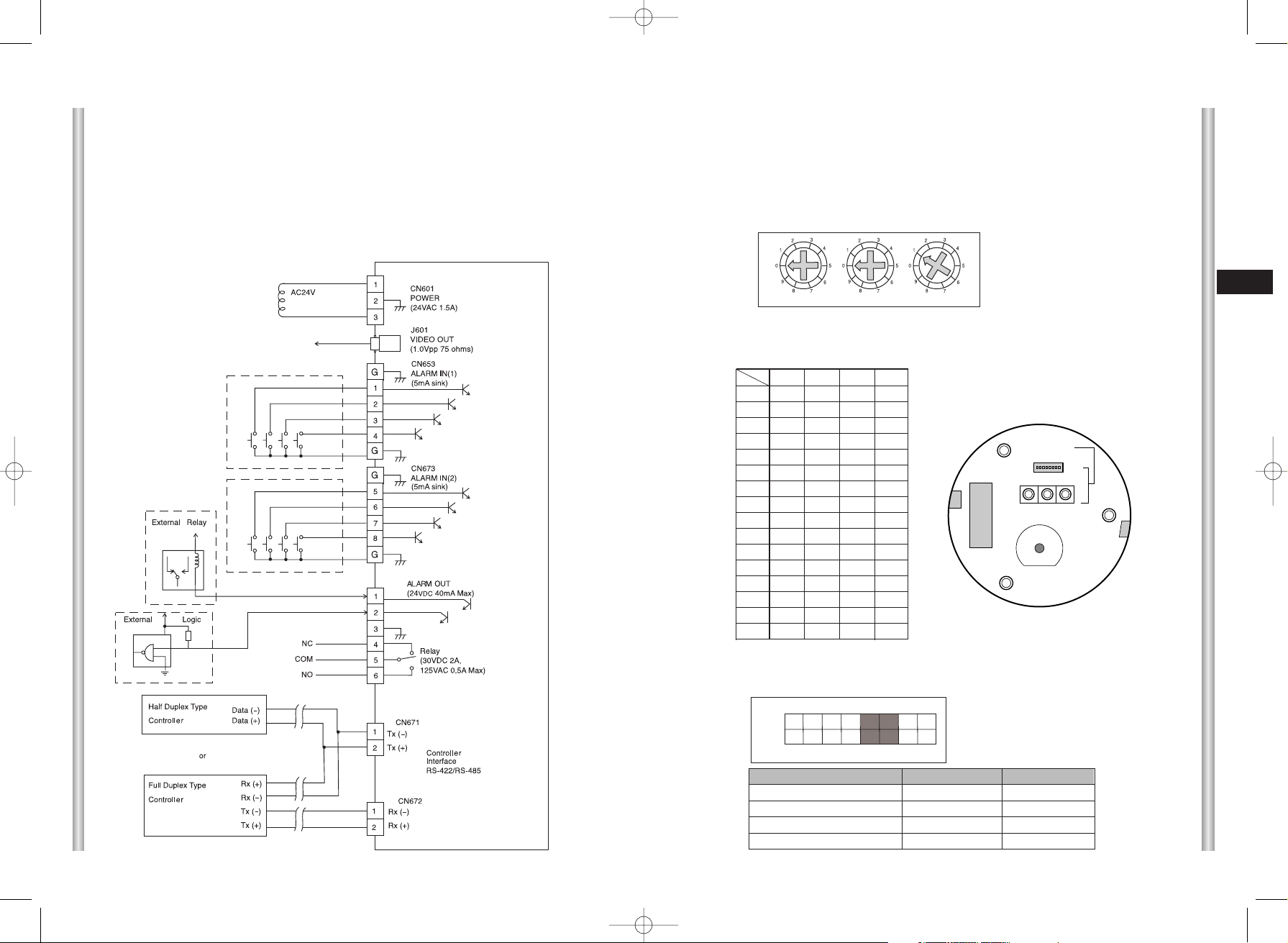
INITIAL SETTING
CAMERA ADDRESS SETUP
Use SW701, SW702, or 703 for Camera Address setup. You may allocate
up to 255 addresses by using SW701 to set the 3rd digit, SW702 the 2nd
digit, and SW703 the 1st digit.
EX) In case of Camera Address 1, see the following figure for setup.
Setting communication Protocol
Use number 1~4 PIN of SW704 to set communication Protocol.
Baud Rate Setting
Use PIN 5 and 6 of SW704.
SW701
SW702
SW703
1 2 3 4 5 6 7 8
ON
OFF
BAUD RATE
4800 BPS
9600 BPS
19200 BPS
38400 BPS
PIN 5
ON
OFF
ON
OFF
PIN 6
ON
ON
OFF
OFF
A : SAMSUNG HALF
B : SAMSUNG FULL
PIN1 PIN2 PIN3 PIN4
A OFF OFF OFF OFF
B ON OFF OFF OFF
C OFF ON OFF OFF
D ON ON OFF OFF
E OFF OFF ON OFF
F ON OFF ON OFF
G OFF ON ON OFF
H ON ON ON OFF
I OFF OFF OFF ON
J ON OFF OFF ON
K OFF ON OFF ON
L ON ON OFF ON
M OFF OFF ON ON
N ON OFF ON ON
O OFF ON ON ON
PONONONON
PIN
Comp
(x100) (x10) (x1)
SW704
ON
1 2 3 4 5 6 7 8
SW701 SW702 SW703
SEE INSTRUCTION MANUAL
(BOTTOM VIEW)
SW 704
ADAPTER CONNECTION
SCC-C6407 Adapter BOARD
The factory default setting is set to 9600BPS.
00600A-SCC-C6407-ENG 8/17/06 3:27 PM ˘ ` 1-9
2-1
E
1-11
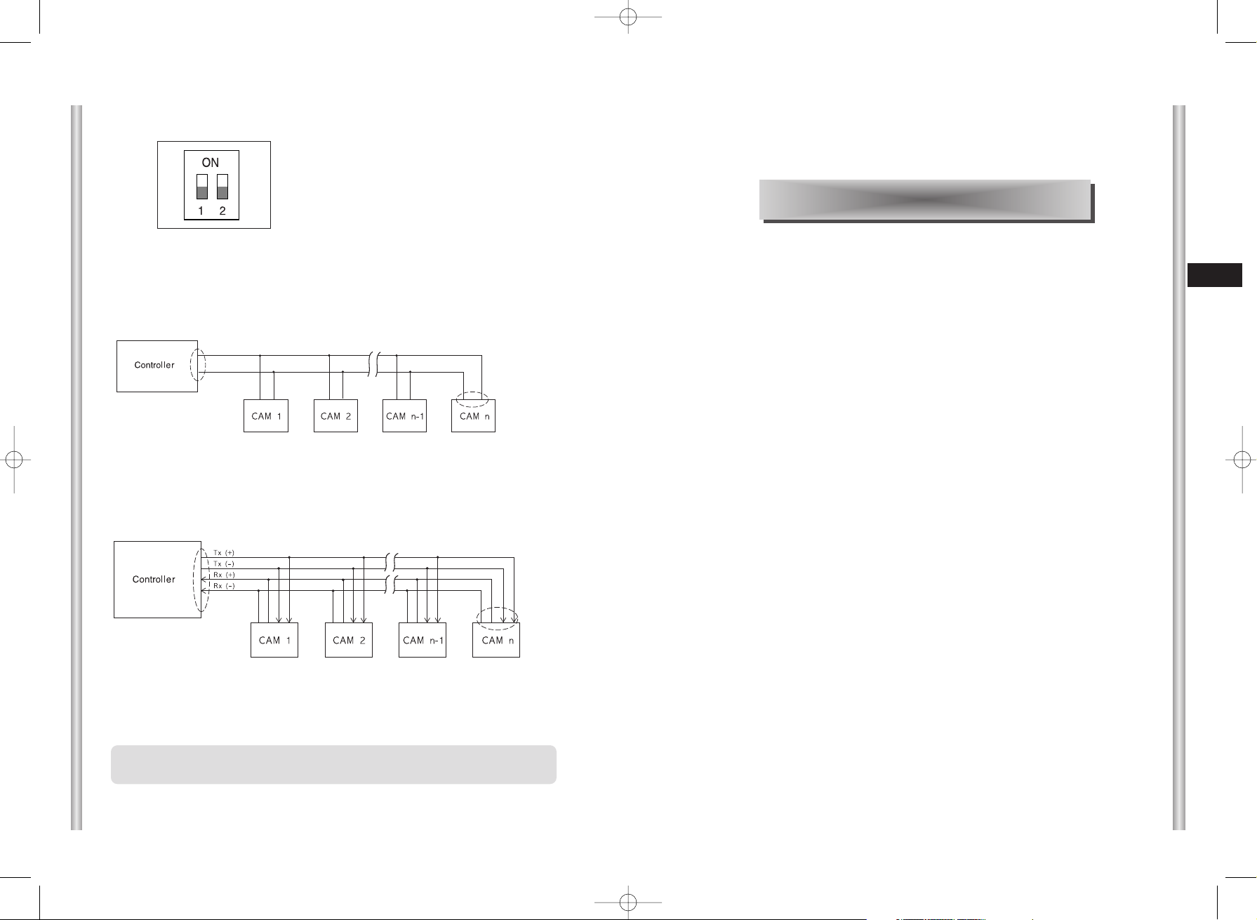
Setting RS-422A/RS-485 termination
As it is shown in the structure map, when Controller and RS-422A/RS485 is connected it should be terminated according to the Cable feature
of impedance on the each end of the transmitting line to transfer the
signals in long distance by controlling the reflection of the signals to the
lowest.
<RS-485 Half Duplex Organization>
n < 32
Termination
SW1-ON
Division
Termination: using numbers 1 and 2 PIN, turn to ON and it will be terminated.
<RS-422A/RS-485 Full Duplex Organization>
Division
Division
SW1-ON
SW2-ON
n < 32
In this chapter, we will check the contents of the package before
installing the SCC-C6407, and prepare a power adapter suitable for
the power supply system.
(Power Consumption: 22W; Voltage: AC24V, 1.5A)
Then, we will install the SCC-C6407 and connect the cables.
Chapter 2 SCC-C6407 Installation
❈
A communication error may occur if you connect multiple cameras
that are assigned the same address in the network.
00600A-SCC-C6407-ENG 8/17/06 3:27 PM ˘ ` 1-11
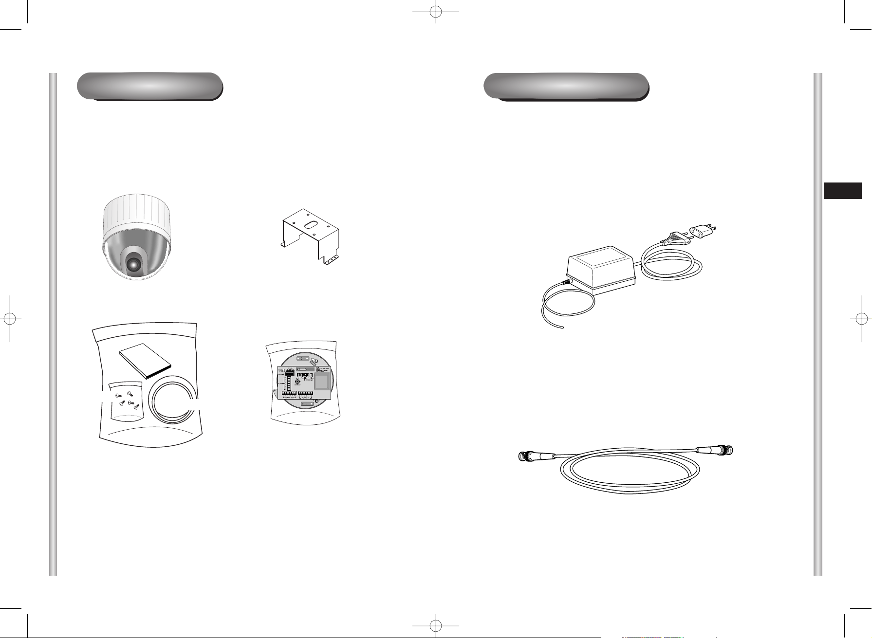
To install and use the SCC-C6407, the following cables should be
prepared.
Power Adapter Cable
The cable that plugs into the SCC-C6407 power input receptacle has the
rated voltage of AC24V, 1.5A.
Check the rated voltage before using the cable.
Video Cable
The SCC-C6407's cable is a BNC Cable for connecting the video-output
terminal to the video-input terminal of the monitor.
Preparing the Cables
2-3
E
2-2
SCC-C6407
Bracket anchor
Camera Holder
Adapter Board
Cover Body
Owner’s
Instructions
Screws
Before Installing
Checking Package Contents
Please check that all components listed below are included in the package:
00600A-SCC-C6407-ENG 8/17/06 3:27 PM ˘` 2-2
 Loading...