


10x Mini Smart
Dome Camera
SCC-C6323P
SCC-C6325P
SCC-C7325P
user manual
imagine the possibilities
Thank you for purchasing this Samsung product.
To receive more complete service,
please register your product at
www.samsungsecurity.com
ENG FRE
GER SPA
ITA
Safety information
CAUTION
RISK OF ELECTRIC SHOCK.
DO NOT OPEN
CAUTION: TO REDUCE THE RISK OF ELECTRIC SHOCK, DO NOT REMOVE REAR COVER. NO USER SERVICEABLE PARTS
INSIDE. REFER TO QUALIFIED SERVICE PERSONNEL..
This symbol indicates high voltage is present inside. It is dangerous to make any kind of
contact with any inside part of this product.
This symbol alerts you that important literature concerning operation and maintenance has
been included with this product.
WARNING
•
To prevent damage which may result in fi re or electric shock hazard, do not expose this appliance to rain or
moisture.
WARNING
1.
Be sure to use only the standard adapter that is specifi ed in the specifi cation sheet. Using any other adapter
could cause fi re, electrical shock, or damage to the product
2.
Incorrectly connecting the power supply or replacing battery may cause explosion, fi re, electric shock, or
damage to the product.
3.
Do not connect multiple cameras to a single adapter. Exceeding the capacity may cause abnormal heat
generation or fi re.
4.
Securely plug the power cord into the power receptacle. Insecure connection may cause fi re.
5.
When installing the camera, fasten it securely and fi rmly. A falling camera may cause personal injury.
6.
Do not place conductive objects (e.g. screwdrivers, coins, metal things, etc.) or containers fi lled with water
on top of the camera. Doing so may cause personal injury due to fi re, electric shock, or falling objects.
7.
Do not install the unit in humid, dusty, or sooty locations. Doing so may cause fi re or electric shock.
8.
If any unusual smells or smoke come from the unit, stop using the product. In such case, immediately
disconnect the power source and contact the service center. Continued use in such a condition may cause
fi re or electric shock.
9.
If this product fails to operate normally, contact the nearest service center. Never disassemble or modify
this product in any way. (SAMSUNG is not liable for problems caused by unauthorized modifi cations or
attempted repair.)
When cleaning, do not spray water directly onto parts of the product. Doing so may cause fi re or electric shock.
10.
If the camera is installed or rebooted after power failure when ambient temperature is below the freezing point,
11.
the dome cover is frosted. In this case, the frost will be disappeared after 3 hours after turning on the power.
(It is noted that lowest guaranteed operating temperature is -45º C (-49º F) without wind.)
2 – 10X MINI SMART DOME CAMERA

Safety information
CAUTION
Do not drop objects on the product or apply strong shock to it. Keep away from a location subject to
1.
excessive vibrationor magnetic interference.
Do not install in a location subject to high temperature (over 50°C), low temperature (below -10°C), or high
2.
humidity. Doing so may cause fi re or electric shock.
If you want to relocate the already installed product, be sure to turn off the power and then move or reinstall
3.
it.
Remove the power plug from the outlet when then there is a lightning. Neglecting to do so may cause fi re or
4.
damage to the product.
Keep out of direct sunlight and heat radiation sources. It may cause fi re.
5.
Install it in a place with good ventilation.
6.
Avoid aiming the camera directly towards extremely bright objects such as sun, as this may damage the
7.
CCD image sensor.
Apparatus shall not be exposed to dripping or splashing and no objects fi lled with liquids, such as vases,
8.
shall be placed on the apparatus.
The Mains plug is used as a disconnect device and shall stay readily operable at any time.
9.
ENG
English – 3
Important Safety Instructions
Read these instructions.
1.
Keep these instructions.
2.
Heed all warnings.
3.
Follow all instructions.
4.
Do not use this apparatus near water.
5.
Clean only with dry cloth.
6.
Do not block any ventilation openings. Install in accordance with the manufacturer’s instructions.
7.
Do not install near any heat sources such as radiators, heat registers, or other apparatus (including amplifi ers) that
8.
produce heat.
Do not defeat the safety purpose of the polarized or grounding-type plug. A polarized plug has two blades with
9.
one wider than the other. A grounding type plug has two blades and a third grounding prong. The wide blade or
the third prong is provided for your safety. If the provided plug does not fi t into your outlet, consult an electrician
for replacement of the obsolete outlet.
Protect the power cord from being walked on or pinched particularly at plugs, convenience
10.
receptacles, and the point where they exit from the apparatus.
Only use attachments/accessories specifi ed by the manufacturer.
11.
Use only with cart, stand, tripod, bracket, or table specifi ed by the manufacturer, or sold
12.
with the apparatus.
Unplug this apparatus when a card is used. Use caution when moving the cart/ apparatus
13.
combination to avoid injury from tip-over.
Refer all servicing to qualifi ed service personnel. Servicing is required when the apparatus has been damaged in
14.
any way, such as powersupply cord or plug is damaged, liquid has been spilled or objects have fallen into the
apparatus, the apparatus has been exposed to rain or moisture, does not operate normally, or has been dropped.
4 – 10X MINI SMART DOME CAMERA

Contents
Introduction
Features 7
Product & Accessories 8
Parts Name & Functions 10
Installation
DIP Switch Setup 13
Installation using Surface mount on the Ceiling 14
Installation using Ceiling Mount Bracket (SCC-C7325) 16
Installation using Wall Mount Bracket (SCC-C7325) 17
Cabling 19
Operation
Check points before operation 21
Preset and Pattern Function Pre-Check 21
Starting OSD Menu 21
Reserved Preset 21
Preset 22
Auto Pan 22
Pattern 22
Scan 23
Schedule 23
Other Functions 23
OSD Display of Main Screen 24
General Rules of Key Operation for Menu 25
Main Menu 25
System Information 25
Display Setup 25
English – 5
ENG

Contents
How to use OSD Menu
Privacy Zone Mask Setup 26
Motion Setup 26
Function Setup 27
PRESET Setup 28
Auto Pan Setup 29
Pattern Setup 30
Scan Setup 30
Schedule Setup 32
Camera Setup 33
System Setup 34
System Initialize 36
Specifi cations
Specifi cations 38
Dimension 41
6 – 10X MINI SMART DOME CAMERA

FEATURES
Camera Specifi cations
❖
CCD Sensor : 1/4” Interline Transfer CCD
•
Zoom Magnifi cation : x10 Optical Zoom, x10
•
Digital Zoom (Max x 100 Zoom)
Day & Night Function
•
Various Focus Mode: Auto-Focus / Manual Focus
•
/ Semi-Auto Focus.
Independent or General Camera Characteristic
•
Setup in Preset operation
Powerful Pan/Tilt Functions
❖
•
Max. 360°/sec high speed Pan/Tilt Motion
•
Using Vector Drive Technology, Pan/Tilt motions
are accomplished in a shortest path. As a result,
time to target view is reduced dramatically and the
video on the monitor is very natural to watch.
•
For jog operation using a controller, since ultra
slow speed 0.05°/sec can be reached, it is very
easy to locate camera to desired target view.
•
Owing to zoom-proportional pan/tilt speed,
camera can be moved to a desired position in
accurate manner even though zoom ratio is high.
Preset, Pattern, Auto Pan, Scan, Privacy
❖
Mask, Schedule and More…
MAX. 127 Presets are assignable and
•
characteristics of each preset can be set up
independently, such as White Balance, Auto
Exposure, Label and so on.
•
Max. 8 Auto Pan can be stored. This enables to
move camera repetitively between two preset
positions with designated speed.
Max. 4 of Patterns can be recorded and
•
executed. This enables for camera to track a
surveillance trajectory as closely as possible which
are recorded from operator’s motion of joystick.
Max. 8 Scan can be stored. To compose a
•
surveillance trajectory, the Group can have max.
20 entities of Preset/Pattern/Scan functions. This
enables for camera to move a combinations of
those functions repetitively.
•
Max. 4 Masks are settable independently to
protect privacy zone. The mask is arbitrary-sized
rectangular and locate any location in view space.
Introduction
•
7 rules of Schedule can be assigned by day and
time. Appropriate actions (such as Home, Preset,
Auto Pan, Pattern, Scan) can be defi ned for each
rule. Also, it is possible to make rule by Weekday
and Allday to simplify the rule.
PTZ(Pan/Tilt/Zoom) Control
❖
With RS-485 communication, max. 255 of
•
cameras can be controlled at the same time.
•
Pelco-D/ Pelco-P, Samsung protocol can be
selected as a control protocol in the current
version of fi rmware.
OSD(On Screen Display) Menu
❖
•
OSD menu is provided to display the status
of camera and to confi gure the functions
interactively.
•
Currently, 7 Languages are supported for
OSD Menu: [ENGLISH/ESPAÑOL/FRANÇAIS/
DEUTSCH/ITALIANO/РУССКИЙ/PORTUGUÊS]
•
The information such as Camera ID, Pan/Tilt/
Zoom/Direction, Alarm Input & Output, date/time,
current temperature and Preset can be displayed
on screen.
•
Each display item can be turned On or Off
independently.
Alarm I/O Functions
❖
2 alarm sensor Inputs and 1 relay output are
•
available.
To reject external electric noise and shock
•
perfectly, alarm sensor Input is decoupled with
photo coupler.
If an external sensor is activated, camera can be
•
set to move to the corresponding Preset position.
Relay output can be assigned to work with a
•
certain preset.
❖
Reserved Presets for Special Purpose
Besides regular 127 presets, direct calling of
•
reserved presets enables to set up many of
camera functions with without using OSD menu.
For more information, refer to “Reserved Preset” in
this manual.
ENG
English – 7
Introduction
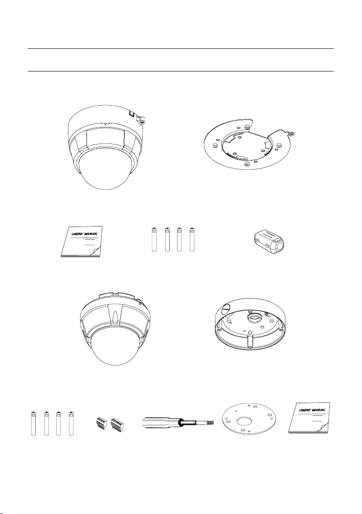
PRODUCT & ACCESSORIES
Product & Accessories (SCC-C6323)
❖
Main Product
•
Main Body Surface Mount Bracket
Accessory
•
Manual
Product & Accessories (SCC-C6325)
❖
Main Product
•
Main Body Surface Mount Bracket
Accessory
•
Screw & Plastic
Anchor (4Pcs)
Mount Bracket Option : Please use SADT-937WM for this purpose.Ú
8 – 10X MINI SMART DOME CAMERA
Terminal Block Torx Screw Driver Surface Mount
G
Screw & Plastic Anchor (4Pcs)
Core fi lter (PAL Option)
Gasket
Manual
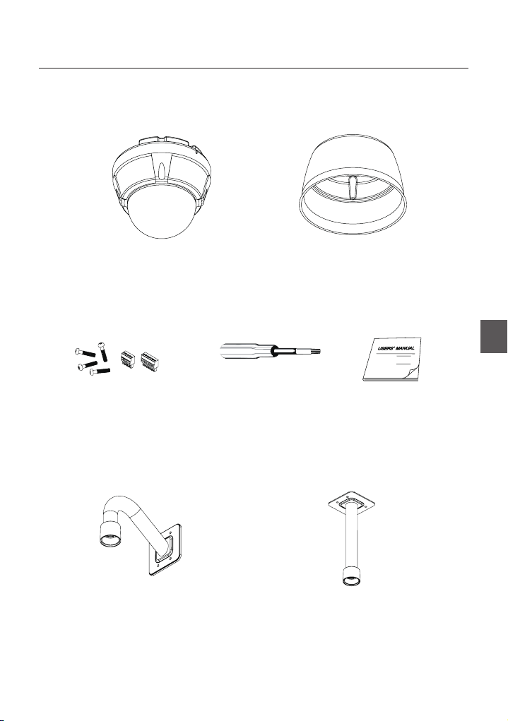
Product & Accessories (SCC-C7325)
❖
Main Product
•
Main Body Sun Shield Housing
Accessory
•
Introduction
ENG
Terminal Block
Mount Bracket Option
•
Torx Screw Driver Manual
Ceiling Mount Bracket (SADT-732CM)Wall Mount Bracket (SADT-732WM)
English – 9

Introduction
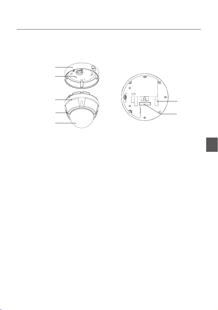
PARTS NAME & FUNCTIONS
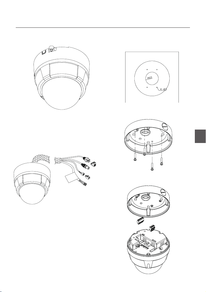
SCC-C6323❖
Surface Mount Bracket
Separating Slit
Dome Cover
Main Unit / Surface Mount Bracket Back of Main Unit
Surface Mount Bracket
•
This is used to install the camera directly on the
ceiling. After separating this cover fi rst and then
attach this directly to ceiling. Camera must be
assembled at the last stage.
Do not use this bracket when installing camera on
the wall with wall mount bracket or on the ceiling with
ceiling mount bracket.
Separating Slit
•
Using a coin, you can separate upper part lower
body of the dome.
Dome Cover
•
Do not detach protection vinyl from dome cover
before fi nishing all installation process to protect
dome cover from scratches or dust.
DIP Switch
•
Adjusts camera ID and protocols.
Cable Duct
•
When you want to install the camera on the surface
of hard ceiling, you need to handle the cable through
side of the dome. In this case, break the side wall bit
and make the cable pass through the cable duct.
DIP Switch
Cable Duct
10 – 10X MINI SMART DOME CAMERA
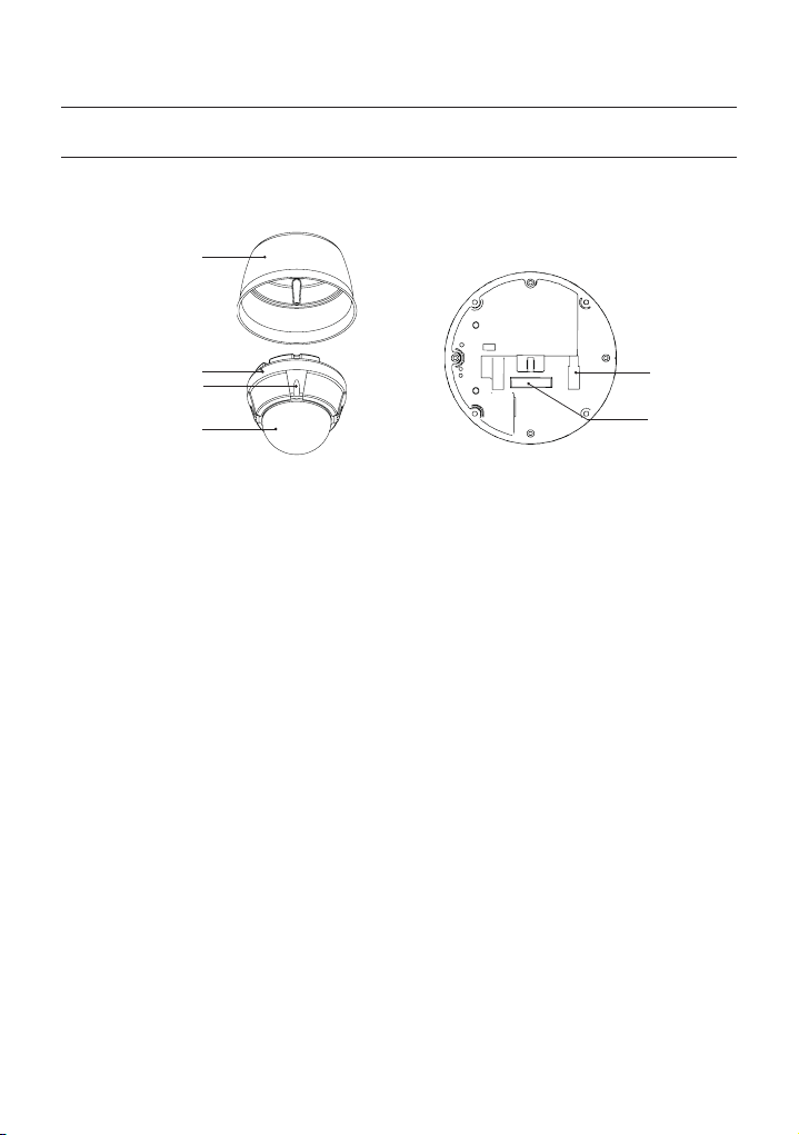
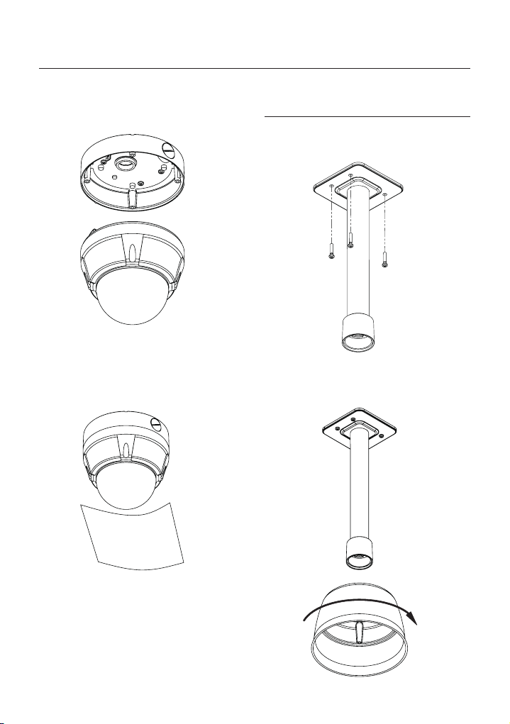
SCC-C6325❖
Surface Mount Bracket
Mounting Hole
Introduction
Main Body
Lockup Screw
Dome Cover
Main Unit / Surface Mount Bracket Back of Main Unit
Dome Cover
•
Do not remove the protection vinyl from dome cover
before fi nishing all installation process to protect
dome cover from scratches or dust.
Surface Mount Bracket
•
This is used to install the camera directly on the
ceiling. After separating this cover, mount this
bracket on to ceiling. Main body of the camera is
going to be assembled again in the last stage.
Do not use this bracket with wall mount bracket or
ceiling mount bracket.
Lockup Screw
•
Fixes main unit brackets like surface, wall, and
ceiling.
Cabling Terminal Block
•
During installation, Power, Video, Communication,
Alarm Input cables are connected on to this cabling
terminal block.
DIP Switch
•
Adjusts camera ID and protocols.
Cabling Terminal
Block
DIP Switch
ENG
English – 11
Introduction
PARTS NAME & FUNCTIONS
SCC-C7325❖
Sun Shield Housing
Main Body
Lockup Screw
Dome Cover
Main Unit / Surface Mount Bracket Back of Main Unit
Dome Cover
•
Do not remove the protection vinyl from dome cover
before fi nishing all installation process to protect
dome cover from scratches or dust.
Sun Shield Housing
•
Lockup Screw
•
Fixes main unit brackets like surface, wall, and
ceiling.
Cabling Terminal Block
•
During installation, Power, Video, Communication,
Alarm Input cables are connected on to this cabling
terminal block.
DIP Switch
•
Adjusts camera ID and protocols.
Cabling Terminal
Block
DIP Switch
12 – 10X MINI SMART DOME CAMERA
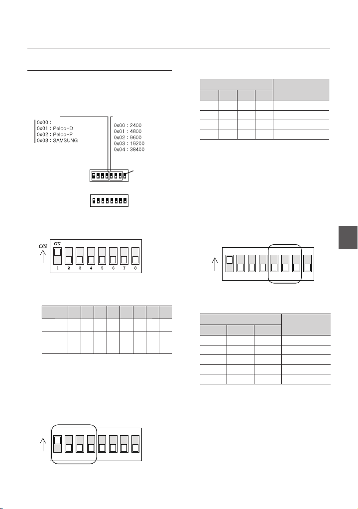
DIP SWITCH SETUP
123456
ON
ON
78
Before you install the camera, you should set the DIP
switches to confi gure the camera ID, Baud rate, and
communication protocol.
Protocol
Auto Select
Camera ID Setup
❖
ID number of camera is set using binary number.
•
The example is shown bellow.
Pin 12345678
ID Value 1 2 4 8 16 32 64 128
ex) ID=5
ex) ID=10onoff
The range of ID is 0~255. Factory default of
•
Camera ID is 1.
If you want to control a certain camera, you must
•
match the camera ID with Cam ID setting of DVR
or Controller.
Communication Protocol Setup
❖
ON
offonon
ON
Buad Rate
ID Setting (1~255)
offonoff
off
RS-485
Terminate
off
off
off
off
off
Installation
•
Select the appropriate Protocol with DIP switch
combination.
Switch State
Pin1 Pin2 Pin3 Pin4
OFF OFF OFF OFF Auto Protocol
ON OFF OFF OFF Pelco-D
OFF ON OFF OFF Pelco-P
ON ON OFF OFF Samsung
•
If you set the protocol as Auto Protocol, camera
will automatically recognize the kind of Protocol.
•
Auto Protocol supports Pelco-D and Samsung Protocol.
•
If you want to control using DVR or system
keyboard, their protocol must be identical to
camera. Otherwise, you can not control the camera.
•
If you changed camera protocol by changing DIP S/W,
the change will be effective after you reboot the camera.
•
Factory default of protocol is “Auto Protocol
Communication Baud rate Setup
❖
Select the appropriate Baud rate with DIP switch
•
combination.
Switch State
off
off
Pin5 Pin6 Pin7
OFF OFF OFF 2400 BPS
ON OFF OFF 4800 BPS
OFF ON OFF 9600 BPS
ON ON OFF 19200 BPS
OFF OFF ON 38400 BPS
•
Factory default of Baud rate is “9600 BPS”
Protocol
ENG
Protocol
123456
78
English – 13
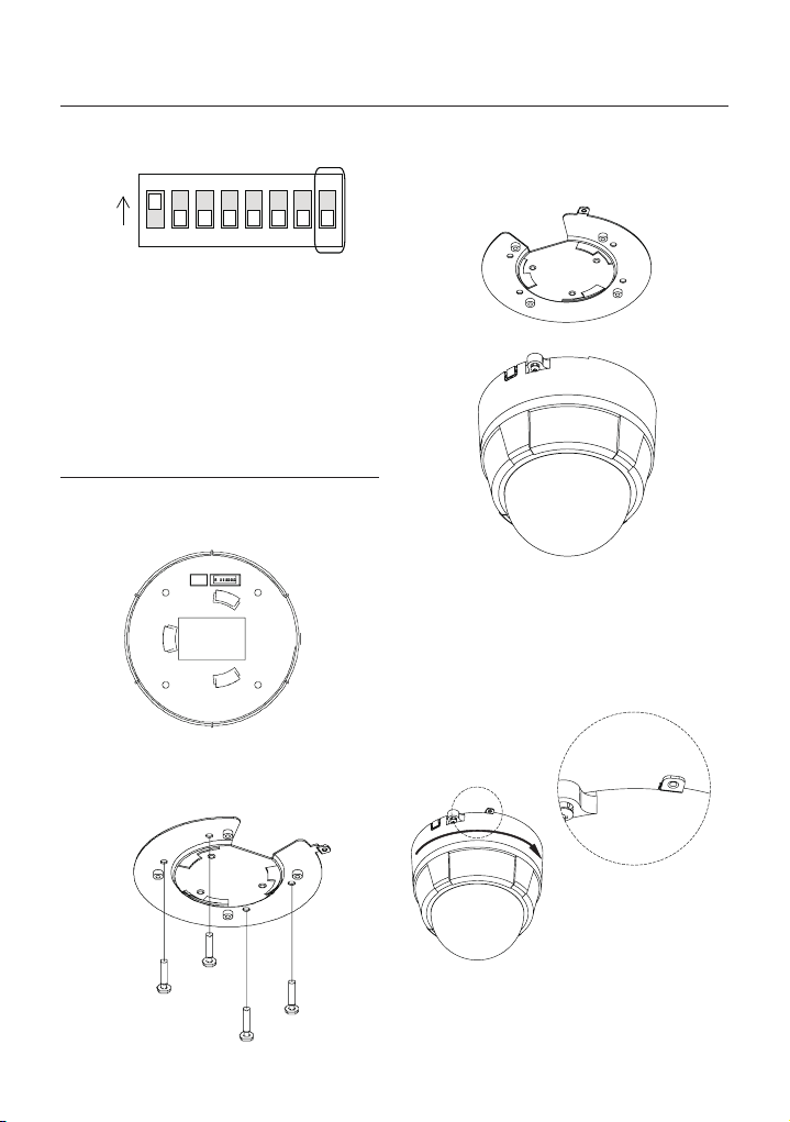
Installation
123456
ON
ON
78
RS-485 Termination Resistor
❖
Pin 8 is used for ON/OFF of RS-485 Termination.
•
Normally, it must be OFF state. Especially when
you have trouble with long Daisy chain style
connection, turn ON this termination switch of last
camera.
Pin 8 RS-485 Termination Resistor (On/Off)
–
INSTALLATION USING SURFACE
MOUNT ON THE CEILING
SCC-C6323
❖
① Setup DIP Switch (see previous page).
② Screw surface mount bracket to ceiling with 4
screws.
③ Placing lower body to Surface Mount bracket.
The cable must be properly handled into hole of
bracket or side of lower body.
④ Make sure stopper pin of bracket pin is located
the rightmost side of lower body groove as
shown in the picture. Press the dome and turn
clockwise till the pin is located leftmost side
of groove. Detach protection vinyl from dome
cover.
14 – 10X MINI SMART DOME CAMERA
G
Installation
⑤ Tighten locking screw.
⑥ Connect Video, communication, power cable
properly. (see next section)
SCC-C6325
❖
① To pass cables to upside of ceiling, please,
make about ũ60mm hole on the ceiling panel.
② Screw surface mount bracket to ceiling with
4 screws.
③ Wire cables to terminal block and connect the
terminal blocks to main unit.
ENG
English – 15
Installation
④ Screw main unit to surface mount bracket with
4 lock-up screws.
⑤ Detach protection vinyl from dome cover.
INSTALLATION USING CEILING
MOUNT BRACKET (SCC-C7325)
① Install ceiling mount bracket on the ceiling using
4 screws provided.
② Turn sunshield clockwise after locating it in the
pipe head of ceiling mount properly.
16 – 10X MINI SMART DOME CAMERA
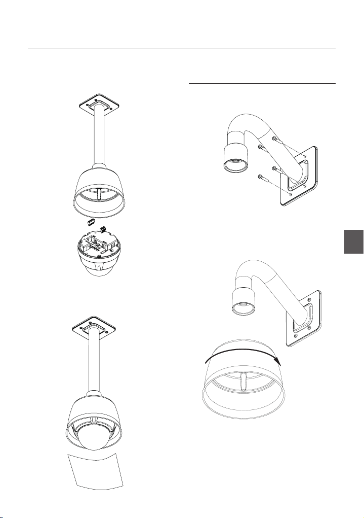
Installation
③ After wiring cables to terminals, plug the
terminals into the bottom of main unit. Then, fi x
the main unit with sunshield with 4 screws.
④ Detach protection vinyl from dome cover.
INSTALLATION USING WALL
MOUNT BRACKET (SCC-C7325)
① Use the 4 screws (provided) to secure the wall
mount bracket to the wall.
② Turn sunshield clockwise after locating it in the
pipe head of wall mount properly.
ENG
English – 17
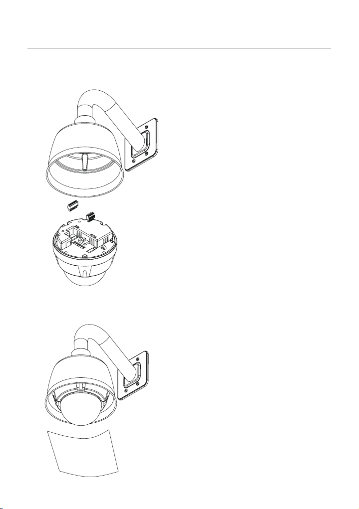
Installation
③ After wiring cables to terminals, plug the
terminals into the bottom of main unit. Then, fi x
the main unit with sunshield with 4 screws.
④ Detach protection vinyl from dome cover.
18 – 10X MINI SMART DOME CAMERA
Installation
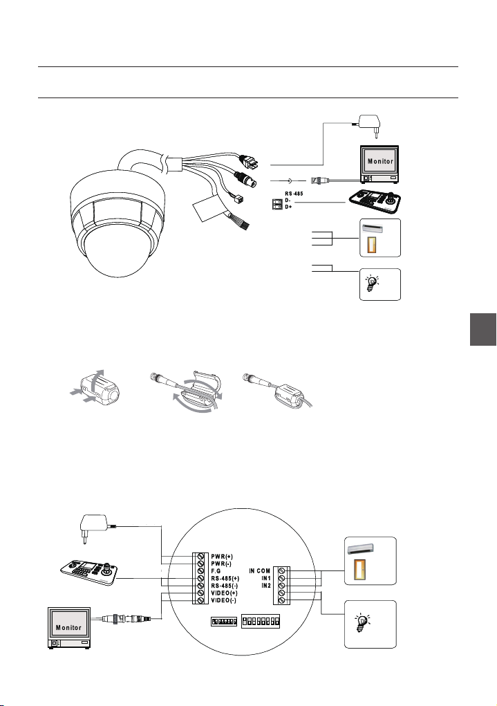
CABLING
SCC-C6323❖
Dual Voltage
DC 12V/AC 24V
BNC Video
Controller/DVR
1 (Black) : IN COM
2 (Yellow) : IN 1
3 (Brown) : IN 2
4 (Red) : Relay Out
5 (Orange) : Relay Out
Attaching the Core fi lter
❖
To reduce interference of electric wave. attach the core fi lter to BNC Cable (PAL Option)
•
Attach the core fi lter closer to the jack of the product.
•
Wind once!
BNC Cable ( PAL Option)
* Note: To attach the core fi lter to BNC Cable, roll the cable over core fi lter once.
* Note: Be careful not to damage the cable when attaching the core fi lter.
Sensors
Relay Out
IrDA
Sensor
Door
Switch
Lamp
ENG
SCC-C6325/ SCC-C7325❖
Dual Voltage
DC 12V/AC 24V
IrDA
Sensor
Door
Switch
Controller/DVR
BNC Video
Relay Out
Relay Out
Cabling Terminal Block
Sensors
Lamp
Relay Out
English – 19
Installation
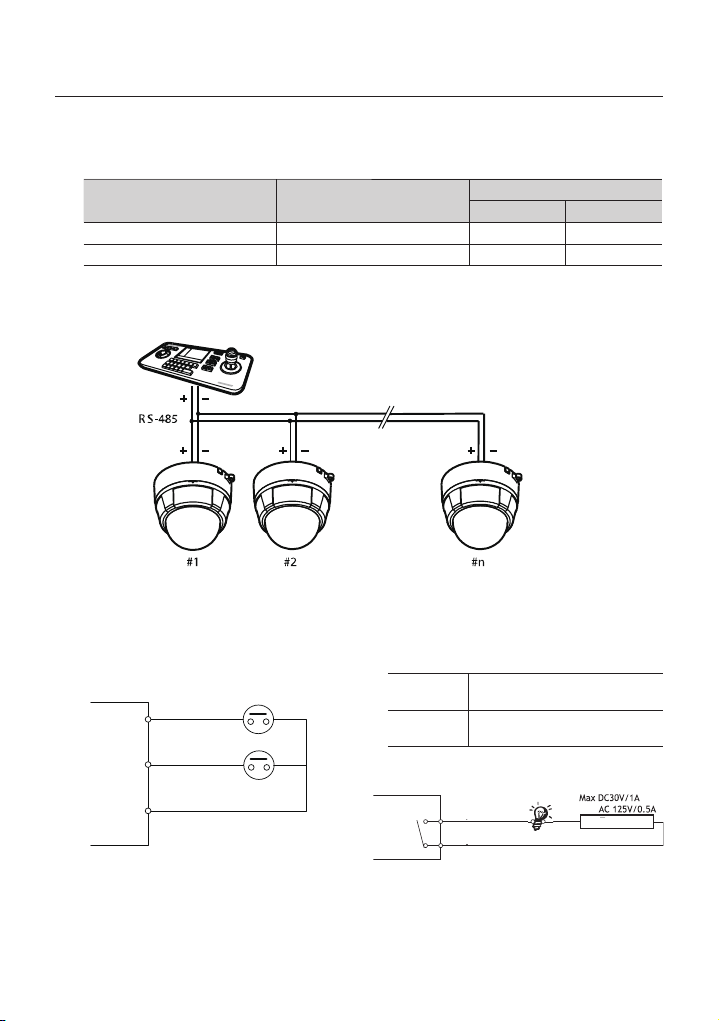
Power Connection
❖
Please, check the voltage and current capacity of rated power carefully. Rated power is indicated in the back of
•
main unit.
Power Mode
DC 12V DC 11V ~ 15V 8 W
AC24V AC 20V ~ 29V 10W
RS-485 Communication
❖
For PTZ control, connect this line to keyboard and DVR. To control multiple cameras at the same time, RS-485
•
communication lines of them is connected in parallel as shown below.
Video Connection
❖
Connect with BNC coaxial cable.
•
Alarm Input Connection
❖
Sensor Input
•
INTERNAL
INTERNAL
IN1
IN2
Input Voltage Range
Keyboard Controller DVR
If you want to use Alarm Input, the types of sensor
must be selected in OSD menu. The sensor types
are Normal Open and Normal. If sensor type is
not selected properly, the alarm can be activated
reversely.
Normal Open
(N.O)
Normal Close
(N.C)
Relay Output
•
Power Consumption
C6323/ C6325 C7325
Sensor output is turned ON when
sensor is activated
Sensor output is turned OFF when
sensor is activated
12W
21W
IN COM
It is noted that short circuit between GND and
Input pin means alarm activation.
20 – 10X MINI SMART DOME CAMERA
Internal
Relay Out
Relay Out
There are 4 Alarm Outputs and all of them are Relay
contact type. Therefore, you do not have to care about
polarity, AC/DC, and isolations between channels. Care
must be taken for the power capacity of relay contact
written above.
Power

Operation
CHECK POINTS BEFORE OPERATION
Before power is applied, please check the cables carefully.
•
The camera ID of the controller must be identical to that
•
of the camera to be controlled. The camera ID can be
checked in the System Information of OSD Menu.
If your controller supports multi-protocols, the protocol
•
must be changed to match to that of the camera.
If you changed camera protocol by changing DIP switch,
•
the change will be effective after you reboot the camera.
Since the operation method can be different for
•
each controller available, refer to the manual for your
controller if camera can not be controlled properly.
PRESET AND PATTERN
FUNCTION PRE-CHECK
Check how to operate Preset, Scan, Auto Pan and
•
Pattern function with controller or DVR in advance to
operate camera function using them. (refer to your
System keyboard Manual)
If controller or DVR has no pattern button or function,
•
use shortcut keys with preset numbers. For more
information, refer to “Reserved Preset” in this manual.
AUTO CALIBRATION
If the camera is continuously subjected to very high
•
temperature (over 50°C or 122°F) environment for a
long time, it is possible for the camera to lose focus.
As a result, you will get blurry image. In this case, it is
recommended to turn on “AUTO CALIBRATION” by
running Preset 165.
If you execute AUTO CALIBRATION, camera will
•
calibrate its focus at every 6 hours. To turn off this
function, please, Run Preset 166.
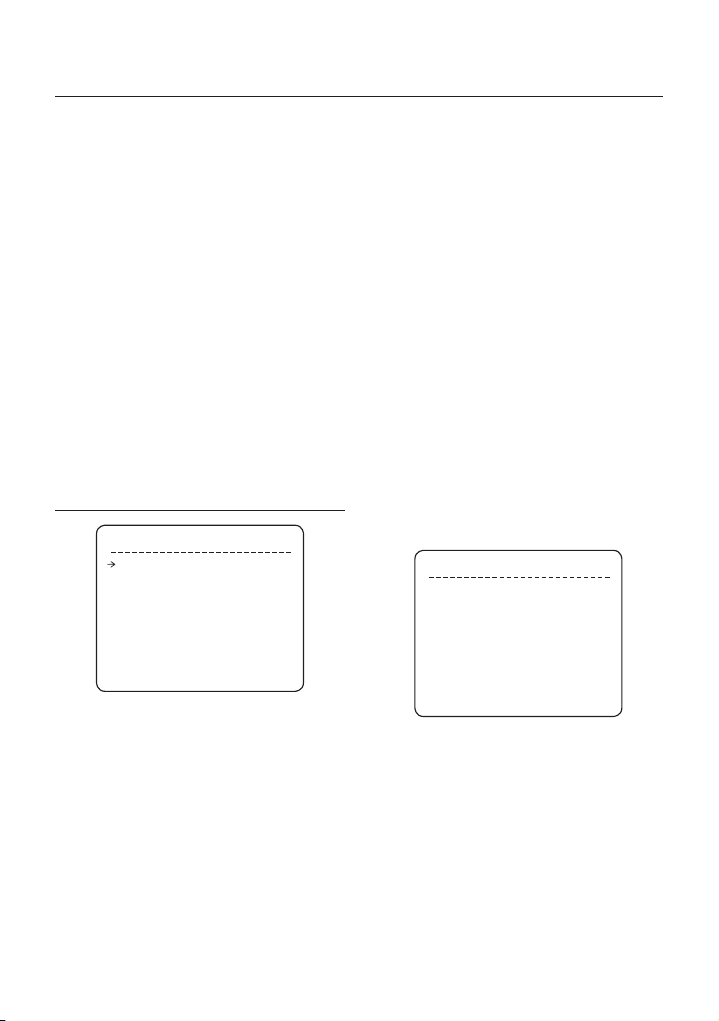
STARTING OSD MENU
Function
•
Using the OSD menu, Preset, Pattern, Auto Pan,
Scan and Alarm Input function can be confi gured for
each application.
Enter Menu
•
<Go Preset> [95]
RESERVED PRESET
Description
•
Some Preset numbers are reserved for direct access
to specifi c functions in OSD menu. These direct
commands via preset provide quick execution of
various functions using keyboard controller as well as
simplify the interface with DVR and IP equipments.
Function
•
<Go Preset> [95] : Enters into OSD menu
<Go Preset> [131~134] : Runs Pattern Function 1 ~ 4
<Go Preset> [141~148] : Runs Auto Pan Function 1 ~ 8
<Go Preset> [151~158] : Runs Scan Function 1 ~ 8
<Go Preset> [161] : Sets Relay Output to OFF
<Set Preset> [161] : Sets Relay Output to ON
<Go Preset> [165] : Auto Calibration ON
<Go Preset> [166] : Auto Calibration OFF
<Go Preset> [167] : Zoom Proportional Jog ON
<Set Preset>[167] : Zoom Proportional Jog OFF
<Go Preset> [170] : Sets Camera BLC Mode to OFF
<Go Preset> [171] :
<Go Preset> [174] : Sets Camera Focus Mode to
<Go Preset> [175] : Sets Camera Focus Mode to
<Go Preset> [176] : Sets Camera Focus Mode to
<Go Preset> [177] : Sets Day & Night Mode to
<Go Preset> [178] : Sets Day & Night Mode to
<Go Preset> [179] : Sets Day & Night Mode to DAY
<Go Preset> [190] : Sets OSD Display Mode to
<Go Preset> [191] : Sets OSD Display Mode to OFF
<Go Preset> [192] : Setting OSD Display Mode to
<Go Preset> [193] : Sets all Privacy Mask Display to
<Go Preset> [194] : Sets all Privacy Mask Display to
<Go Preset> [195] : Heater ON (Turn off after 5mins
<Go Preset> [196] : Heater OFF (Turn off and switch
<Go Preset> [197] : Fan ON (Turn off after 5mins
<Go Preset> [198] : Fan OFF (Turn off and switch to
<Go Preset>[200] : Digital Zoom ON
<Go Preset>[201] : Digital Zoom OFF
Sets Camera BLC Mode to HIGH
AUTO
Manual
SEMI-AUTO
AUTO1
NIGHT
AUTO (Except Privacy Mask)
(Except Privacy Mask)
ON (Except Privacy Mask)
OFF
ON
and switch to Auto mode)
to Manual mode)
and switch to Auto mode)
Manual mode)
English – 21
ENG
Operation
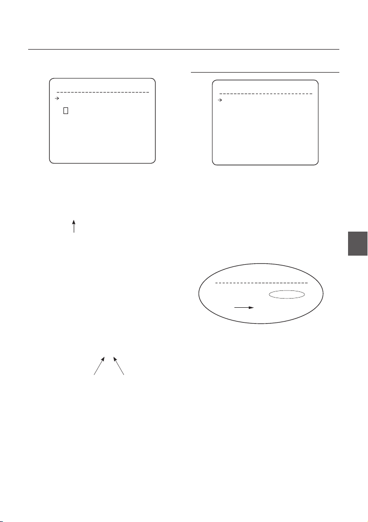
PRESET
Function
•
Max. 127 positions can be stored as Preset position.
The Preset number can be assigned from 1 to 128. It
is noted that preset “95” is reserved for starting OSD
menu.
Camera characteristics (i.e. White Balance, Auto
Exposure) can be set up independently for each
preset and they are adjusted by using OSD menu.
Four relay outputs can be controlled in conjunction
with one Preset.
Set Preset
•
<Set Preset> [1~128]
Run Preset
•
<Go Preset> [1~128]
Delete Preset
•
To delete Preset, use OSD menu.
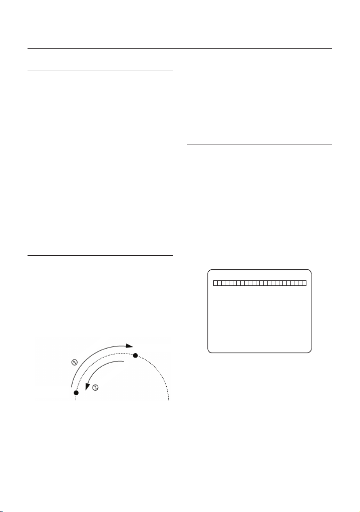
AUTO PAN
Function
•
By using Auto Pan function, you can make camera
to move between 2 Preset positions repeatedly.
When Auto Pan function runs, camera moves
from the preset assigned as the 1st point to the
preset assigned as the 2nd point in CW(Clockwise)
direction. Then camera moves from the preset
assigned as the 2nd point to the preset assigned as
the 1st point in CCW(Counterclockwise) direction.
2nd Preset
CW
Direction
Run Auto Pan
•
Method1) <Run Auto Pan> [Auto Pan NO.] [Enter]
Method2) <Go Preset> [Auto Pan NO.+140]
ex) Run Auto Pan 2 : <Go Preset> [142]]
Delete Auto Pan
•
To delete Auto Pan, use OSD menu.
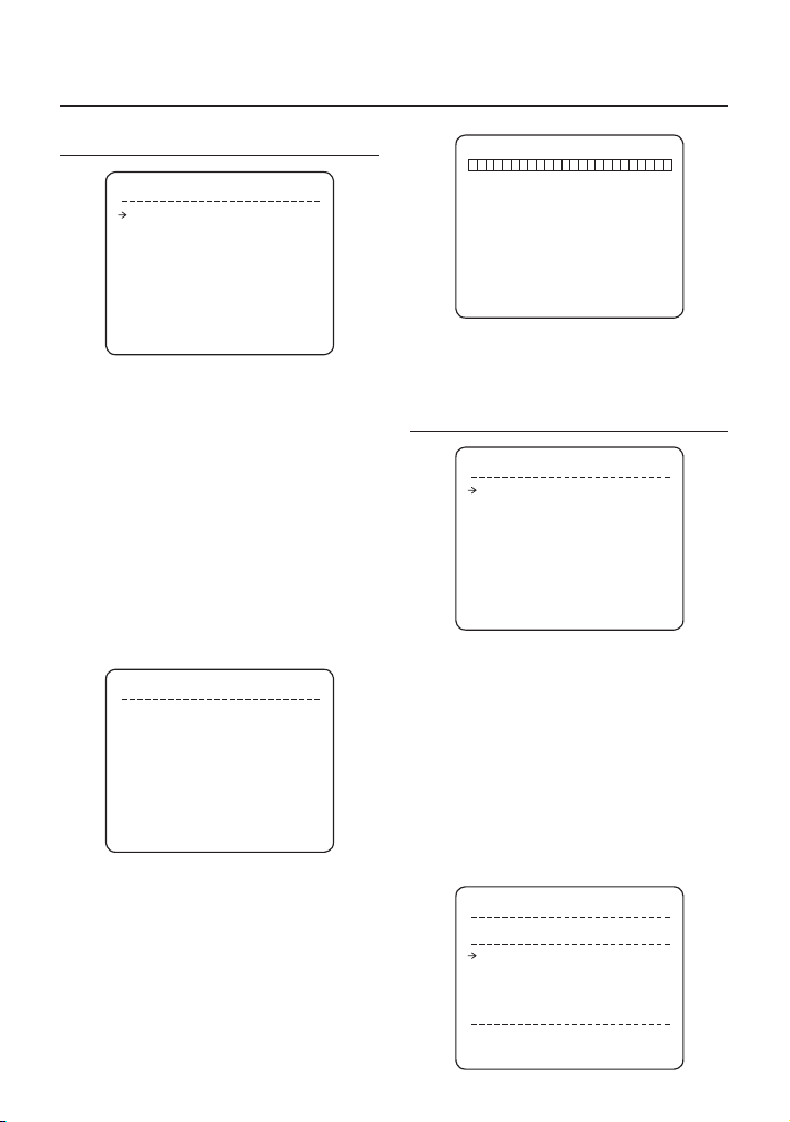
PATTERN
•
Function
Pattern Function enables to memorize the path (mostly
curve path) created by keyboard controller. By running
the pattern, the memorized path can be reconstructed
exactly as it memorized whenever required.
4 Patterns are available and Maximum 1200
communication commands can be stored in a pattern.
•
Set Pattern
Pattern can be created by one of following two
methods.
Method 1) <Set Pattern> [Pattern NO.]
–
Pattern editing screen is displayed as bellow.
EDIT PATTERN 1
[NEAR:SAVE / FAR:DELETE]
0/0/X1/N
1st Preset
In case that the preset assigned as the 1st point
is same as the preset assigned as the 2nd point,
camera turns on its axis by 360˚ in CW(Clockwise)
direction and then it turns on its axis by 360˚ in
CCW(Counterclockwise) direction.
Speed can be set up from 1˚/sec to 180˚/sec.
Set Auto Pan
•
To set Auto Pan, use OSD menu.
22 – 10X MINI SMART DOME CAMERA
CCW Direction
–
Movement by Joystick and preset movement
can be memorized in a pattern.
–
The rest memory size is displayed in progress
bar.
To save the recording, press NEAR key and to
–
cancel, press FAR key.
Method 2) OSD Using OSD Menu:
See the section “How to use OSD Menu”.
Run Pattern
•
Method 1) <Run Pattern> [Pattern NO.]
ex) Run Pattern 2 : <Run Pattern> [2]
Method 2) <Go Preset> [Pattern NO.+130]
ex) Run Pattern 2: <Go Preset> [132]
Delete Pattern
•
Use OSD menu to delete a Pattern.
When the pattern is saved or executed, the PAN/TILT
is operated with Auto Flip OFF mode.
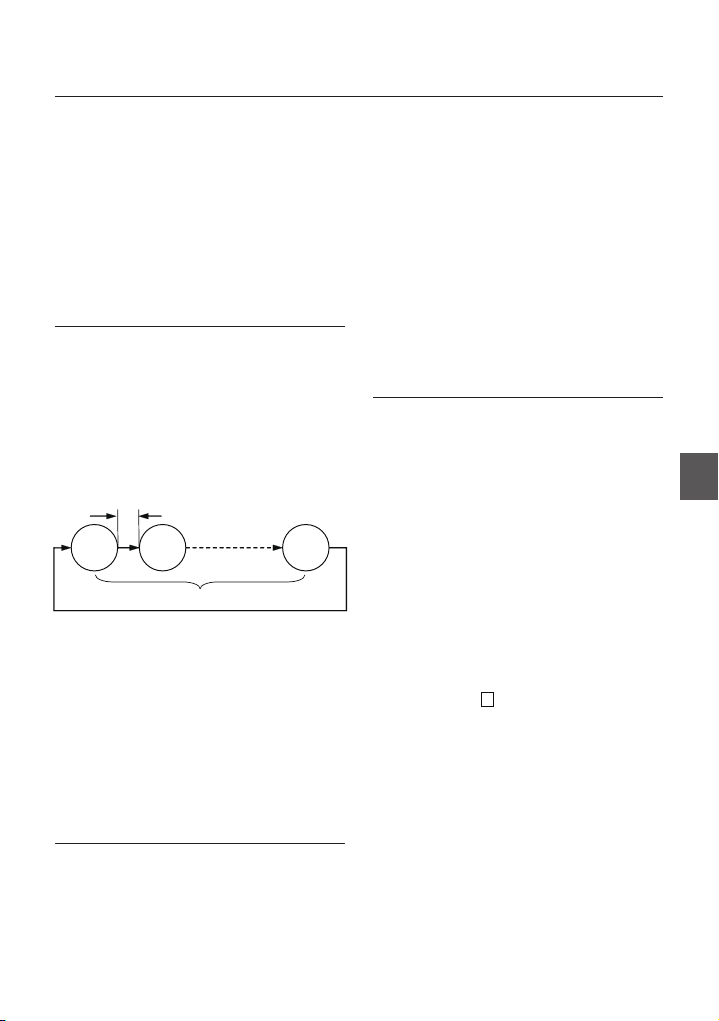
SCAN
•
Function
The Scan function allows running sequence of Presets,
Patterns and/or Auto Pans. Max 8 Scan can be stored.
Each Scan can have max 20 action entities which
can be preset, pattern or Auto Pan. Dwell time means
the time interval between actions and is adjustable in
the menu. Besides, there is an option number with
which Preset speed as well as the repetition number of
Pattern and Auto Pan can be set up.
Dwell Time
Set Scan
•
Preset 1
Pattern 5
Max 20 entities
Auto Pan 5
Use OSD Menu to create a Scan .
Run Scan
•
Method1) <Run Scan> [Scan No.]
ex) Run Scan 2 : <Run Scan> [2]
Method2) <Run Preset> [Scan No.+150]
ex) Run Scan 2 : <Run Preset> [152]
Delete Scan
•
Use OSD Menu to delete.
SCHEDULE
Function
•
The Schedule function allows running an appropriate
function like Preset, Auto Pan, Pattern, Scan, Home
move at designated day and time. For example, if you
setup a rule Tuesday at 9:00AM and Preset 1 (say
Main Gate), the camera will move to main gate every
Operation
Tuesday at 9:00AM. If you choose Weekday, camera
will move to Main gate everyday except weekend.
It is noted that due to the real time clock, the time data
will be kept regardless of blackout. The initial time and
day setup is essential to proper Schedule function.
Set Schedule
•
Use OSD Menu to create a Schedule
Run Schedule
•
Use OSD Menu of Schedule Master Enable
Delete Schedule
•
Use OSD Menu to delete.
OTHER FUNCTIONS
Preset Lock
•
This function is made to protect preset data from
unauthorized overwriting. If Preset Lock is ON,
Preset save command using Hot Key is disabled
while Preset save using OSD Menu is acceptable.
•
Power Up Action
This function enables to resume the last action
executed before power down. Most of actions such
as Preset, Pattern, Auto Pan and Scan are available
for this function but Jog actions are not available to
resume.
Auto Flip
•
In case that tilt angle arrives at the top of tilt orbit
(90°), zoom module camera keep moving to opposite
tilt direction (180°) to keep tracing targets. As soon
as zoom module camera passes through the top
of tilt direction (90°), images should be reversed
automatically and
function is set to OFF, tilt movement range is 0 ~ 90°.
Parking Action
•
This function enables to locate the camera to specifi c
position automatically if operator doesn’t operate the
controller for a while. The Park Time can be defi ned
as an interval from 1 minute to 4 hours.
Alarm Input
•
2 Alarm Inputs are used. If an external sensor
is activated, camera can be set to move to
corresponding preset position. It is noted that the
latest alarm input is effective if multiple sensors are
activated.
appears in screen. If this
F
ENG
English – 23
Operation
Privacy Zone Mask
•
To protect privacy, MAX. 4 Privacy Masks can be
created on the arbitrary position to hide objects such
as windows, shops or private house. With Spherical
Coordinates system, powerful Privacy Zone Mask
function is possible.
GENERAL/SPECIAL Image Setup
•
WB(White Balance) and AE(Auto Exposure) can
be set up independently for each preset. There
are 2 modes, “General” mode & “Special” mode.
The General mode means that WB or AE can be
set up totally and simultaneously for all presets in
“ZOOM CAMERA SETUP” menu. The Special mode
means that WB or AE can be set up independently
or separately for each preset in each preset setup
menu. Each Special WB/AE value should activate
correspondingly when camera arrives at each preset
location.
During jog operation, General WB/AE value should be
applied. All Special WB/AE value will not be changed
regardless of General WB/AE value change.
•
Semi Auto Focus
This mode enables to switch focus mode
automatically operation by operation. Manual focus
mode is selected during preset operation and Auto
focus mode is recovered if jog operation is started.
During Preset action, instead of auto focusing,
manual focus data stored when it is created will be
applied as soon as camera arrives to the preset.
This is helpful to get well-focused image in a short time.
P/T/Z INFORMATION
•
Current Pan/Tilt angle in degree, zoom magnifi cation
and a compass direction.
Camera ID
•
Current Camera ID(Address).
Action Title
•
Followings are possible Action Titles and their
meaning.
“SET PRESET ×××” When Preset ××× is stored
“PRESET ×××” When camera reach to
Preset ×××
“PATTERN ×” When Pattern × is in action
“AUPx/PRESET XXX” When Auto Pan x is in action
“UNDEFINED” When undefi ned function is
Preset Label
•
called to run
The Label stored for specifi c Preset.
Alarm Information
•
This information shows current state of Alarm Input.
The “I” means Input and “O” is output. If an Input is
ON state it will show the number of input. If an Input
is OFF state, ‘-’ will be displayed. In the same way
“O:1” means output 1 is ON “O:-“ is OFF.
Ex) When Point 2 of inputs are ON, and Output 1 is
On, OSD will show as below
I:-2 0:1
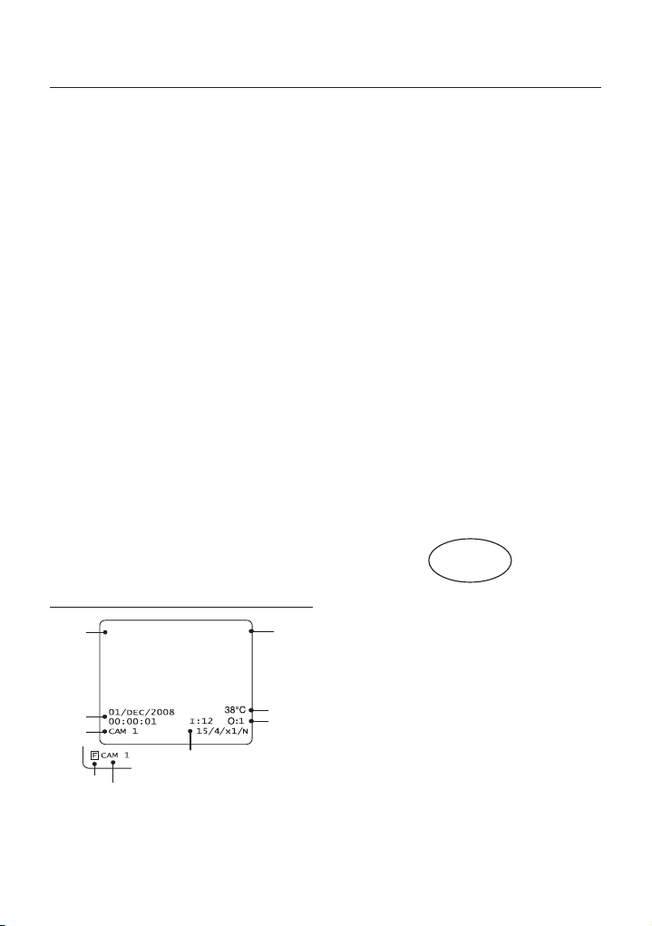
OSD DISPLAY OF MAIN SCREEN
Preset Lable 1
Date/Time
Camera ID
24 – 10X MINI SMART DOME CAMERA
LABEL12345 PRESET1
Image Flip
Camera ID
P/T/Z Information
Temperature
Alarm
Information
Action Title
Image Flip
•
Shows that images are currently reversed by Auto
Flip Function.
Temperature
•
Current Temperature: Boxed “C” and “F” means
Celsius and Fahrenheit respectively
•
Date/Time
Displays Current Date and Time.
How to use OSD Menu
GENERAL RULES OF KEY
OPERATION FOR MENU
The menu item surrounded with < > always means
•
it has its sub menu.
For all menu level, to go into sub menu, press NEAR or
•
ENTER key.
To go to up-one-level menu, press FAR key.
•
To move from items to item in the menu, use joystick
•
in the Up/Down or Left/Right.
To change a value of an item, use Up/Down of the
•
joystick in the controller.
NEAR or ENTER
Press
•
FAR key to cancel values.
key to save values and Press
MAIN MENU
ROOT MENU
<SYSTEM INFORMATION>
<DISPLAY SETUP>
<MOTION SETUP>
<FUNCTION SETUP>
<CAMERA SETUP>
<SYSTEM SETUP>
<SYSTEM INITIALIZE>
EXIT
•
SYSTEM INFORMATION
Shows System information such as current fi rmware
version and communication settings.
•
DISPLAY SETUP
Enable/Disable of OSD display on Main Screen.
•
MOTION SETUP
Setup for motion related settings
•
FUNCTION SETUP
Setup for various functions such as Preset, Auto
Pan, Pattern, Scan and Schedule.
•
CAMERA SETUP
Confi gure Camera related functions and data
•
SYSTEM SETUP
Confi gure for Basic system setup.
•
SYSTEM INITIALIZE
Initializes system confi guration and sets all data to
factory default confi guration.
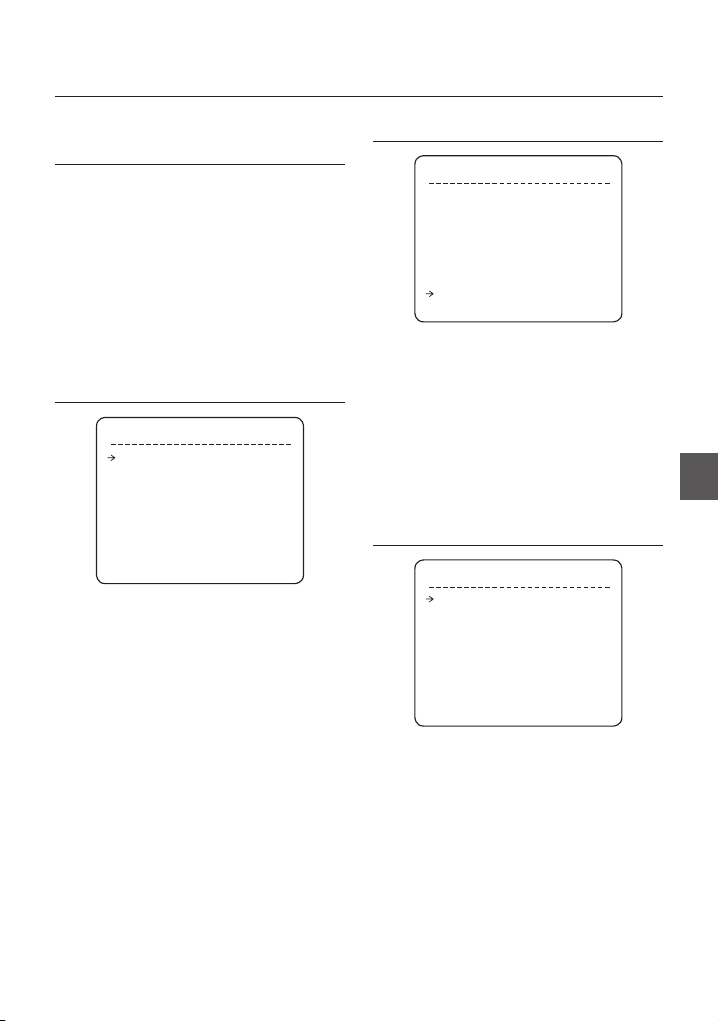
SYSTEM INFORMATION
SYSTEM INFORMATION
FIRMWARE VER 1.0250
COLOR SYSTEM NTSC
PROTOCOL SAMSUNG
BAUD RATE 9600
ADDRESS 255
BACK
EXIT
FIRMWARE VER.
•
Shows current fi rmware version of camera.
COLOR SYSTEM
•
Shows current analog video system of the camera.
PROTOCOL Shows current Protocol for PTZ
•
BAUD RATE Shows current Baud rate of PTZ
•
ADDRESS Shows current Camera ID for PTZ
•
control
control.
control.
DISPLAY SETUP
DISPLAY SETUP
CAMERA ID ON
PTZ INFORMATION AUTO
ACTION TITLE AUTO
RESET LABEL AUTO
ALARM I/O AUTO
DATE/TIME ON
<PRIVACY ZONE>
TEMPERATURE CELSIUS
BACK
EXIT
This menu defi nes Enable/Disable of OSD display on
Main Screen. If an item is set to be AUTO, the item is
displayed only when the value of it is changed.
CAMERA ID [ON/OFF]
•
PTZ INFORMATION [ON/OFF/AUTO]
•
ACTION TITLE [ON/OFF/AUTO]
•
PRESET LABEL [ON/OFF/AUTO]
•
ALARM I/O [ON/OFF/AUTO]
•
DATE/TIME [ON/OFF]
•
•
TEMPERATURE
[CELSIUS/FAHRENHEIT/OFF]
ENG
English – 25
How to use OSD Menu
❖
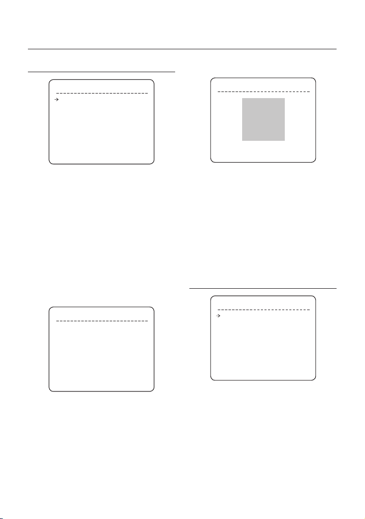
PRIVACY ZONE MASK SETUP
Privacy Zone Size Adjustment
PRIVACY ZONE
MASK NO. 1
UNDEFINED
DISPLAY OFF
CLEAR MASK CANCEL
<EDIT MASK>
BACK
EXIT
Select area in image to mask.
MASK NO. [1~4]
•
Select Mask number. If the selected mask has
already data, camera moves as it was set.
Otherwise, “UNDEFINED” will be displayed under
“Mask NO”.
DISPLAY [ON/OFF]
•
Sets if camera makes mask shows or not on images.
CLEAR MASK [CANCEL/OK]
•
Deletes data in the selected MASK NO.
Privacy Zone Area Setup
❖
EDIT MASK 1
MOVE TO TARGET POSITION
[NEAR:SELECT/FAR:CANCEL]
Move camera to area to mask. Then the menu to adjust
mask size will be displayed.
0/0/x1/N
EDIT MASK 1
:ADJUST MASK WIDTH]
[
:ADJUST MASK HEIGHT]
[
[NEAR:SELECT/ FAR:CANCEL]
Adjust mask size. Use joystick or arrow buttons to
adjust mask size.
(Left/Right) Adjusts mask width.
•
•
It is noted that during PAN/TILT control like jog
action, the object behind the privacy mask can be
disclosed in a short period of time.
To hide a certain zone completely regardless of high
speed PT motions, it is recommended that the size
of mask must be 20% bigger than original target size
(Up/Down) Adjusts mask height.
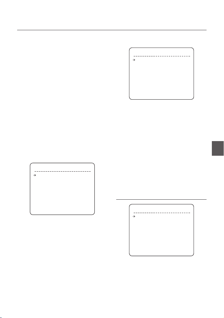
MOTION SETUP
MOTION SETUP
PRESET LOCK ON
PWR UP ACTION ON
AUTO FLIP ON
JOG MAX SPEED 140/SEC
JOG DIRECTION NORMAL
FRZ IN PRESET OFF
<PARKING ACTION SETUP>
<ALARM INPUT SETUP>
BACK
EXIT
Setup the general functions of Pan/Tilt motions.
•
PRESET LOCK [ON/OFF]
This function is made to protect preset data from
unauthorized overwriting. If Preset Lock is ON, it is
impossible to create and delete Preset, Auto Pan,
Pattern and Scan. It is only possible to run those
functions. To create and delete those functions, use
OSD menu.
•
POWER UP ACTION [ON/OFF]
Refer to “Other Functions” section.
26 – 10X MINI SMART DOME CAMERA
How to use OSD Menu
AUTO FLIP [ON/OFF]
•
Refer to “Other Functions” section.
JOG MAX SPEED [2°/sec ~360°/sec]
•
Sets maximum jog speed. Jog speed is inversely
proportional to zoom magnifi cation. As zoom
magnifi cation goes up, pan/tilt speed goes down.
JOG DIRECTION [INVERSE/NORMAL]
•
If you set this to ‘Normal’, the view in the screen is
moving same direction with jog tilting. If ‘Inverse’ is
selected, the view in the screen is moving reversely.
FREEZE IN PRESET [ON/OFF]
•
At start point of preset movement, camera starts
freezing the image of start point. Camera keeps
displaying the image of start point during preset
movement and does not display the images which
camera gets during preset movement. As soon as
camera stops at preset end point, camera starts
displaying live images which it gets at preset end
point.
This function availability should be different by
models.
Parking Action Setup
❖
PARKING ACTION SETUP
PARK ENABLE OFF
WATT TIME 00:10:00
PARK ACTION HOME
BACK
EXIT
If Park Enable is set to ON, camera runs assigned
function automatically if there is no PTZ command
during assigned “Wait Time”.
•
PARK ENABLE [ON/OFF]
•
WAIT TIME [5 seconds ~ 4 hour]
The time is displayed with “hh:mm:ss” format and
you can change this by 1 min unit.
•
PARK ACTION
Ex) If HOME is selected for Park Action, camera
will move to home position when there is no PTZ
command during assigned “Wait Time.”
[HOME/PRESET/PATTERN/
AUTO PAN/SCAN]
Alarm Input Setup
❖
ALARM INPUT SETUP
ALARM1 N.O PRESET1
ALARM2 N.C NOT USED
BACK
EXIT
Match the Alarm sensor input to one of Preset
positions. If an external sensor is activated, camera
will move to corresponding preset position when this
item is predefi ned.
ALARM TYPE
•
[Normal OPEN(N.O) / Normal CLOSE](N.C)]
Sets sensor input type.
ALARM ACTION
•
[NOT USED/HOME/PRESET 1~128/SCAN 1~8,
PATTERN1~4, SCAN 1~4]
For each Alarm input, you can assign
counteraction functions (Preset, Auto Pan, Pattern
and Scan).
FUNCTION SETUP
FUNCTION SETUP
<PRESET SETUP>
<AUTO PAN SETUP>
<PATTERN SETUP>
<SCAN SETUP>
<SCHEDULE SETUP>
BACK
EXIT
Confi gure 5 Special Functions with this menu
•
PRESET SETUP
127 Presets from the number 1 to 128 can be
assigned excluding preset 95 reserved for Menu.
ENG
English – 27
How to use OSD Menu
AUTO PAN SETUP
•
Up to 8 Auto Pans are available, which makes
camera to move slowly between two preset points.
PATTERN SETUP
•
Up to 4 patterns can be stored in the dome.
In this function, path data created by manual move
of Joystick are recorded and you can playback the
identical path automatically whenever required.
SCAN SETUP
•
Up to 8 Scans can be defi ned.
In a Scan, max 20 entities are assigned from any
combinations of Preset/Auto Pan/Pattern. If you run
a Scan, camera will execute each entry sequentially.
SCHEDULE SETUP
•
7 rules of Schedule can be assigned by day and
time. Appropriate actions (such as Home, Preset,
Auto Pan, Pattern and Scan) can be defi ned for
each rule. Also, it is possible to use Weekday and
Weekend in a rule to make it simple.
PRESET SETUP
PRESET SETUP
PRESET NO. 1
<EDIT SCENE>
<LABEL>
CLR PRESET CANCEL
CAM ADJUST GENERAL
ALARM OUT -
BACK
EXIT
•
PRESET Number [1~128]
If a selected preset is already defi ned, camera moves
to pre-defi ned position and preset characteristics
such as Label and Relay Outputs show on monitor.
If a selected preset is not defi ned, “UNDEFINED”
shows on monitor.
•
EDIT PRESET SCENE
Redefi ne current Preset scene position (i.e. PTZ).
•
EDIT PRESET LABEL
Edits Label to show on monitor when preset runs.
MAX. 10 alphabets are allowed.
•
CLEAR PRESET [CANCEL/OK]
Delete current Preset data
NORTH GATE
CAM ADJUST [GENERAL/SPECIAL]
•
WB(White Balance) and AE(Auto Exposure) can
be set up independently for each preset. There are
2 modes, “General” mode & “Special” mode. The
General mode means that WB or AE can be set up
globally for all presets in “CAMERA SETUP” menu.
The Special mode means that WB or AE can be set
up independently or separately for each preset in
each preset setup menu. Each Special WB/AE value
will be applied when camera arrives to the preset
location. During jog operation, General WB/AE value
should be applied.
All Special WB/AE value will not be affected by
General WB/AE value changes. If “Special’’ is
selected, Menu to set WB/AE shows on monitor.
Its default is GENERAL.
ALARM OUT
•
Relay Output can be linked with Preset run.
The character“-“means disable while the number “1”
representing each bit means ON.
Ex) If it is set to “1”, Output relay will be ON whenever
you call this Preset.
Edit Preset Scene
❖
EDIT SCENE - PRESET 1
MOVE TO TARGET POSITION
[NEAR:SELECT/ FAR:CANCEL]
① Using Joystick, move camera to desired
position.
② By pressing NEAR or ENTER key, save current
PTZ data.
③ Press FAR key to cancel.
0/0/x1/N
28 – 10X MINI SMART DOME CAMERA
Edit Preset Label
❖
How to use OSD Menu
AUTO PAN SETUP
LABEL - PRESET 1
[█ ]
--------- 1234567890 OK
ABCDEFGHIJ CANCEL
KLMNOPQRST
UVWXYZabcd
efghijklmn
opqrstuvwx
yz<>-/:.
----------
①
Edits label to show on monitor when camera
arrives at presets. In Edit Label menu, a reverse
rectangular is cursor. As soon as fi nishing
selecting alphabet, cursor moves to the next digit.
[█ ]
Current Cursor Position
② Using Left/Right/Up/Down of joystick, move to
an appropriate character from the Character set.
To choose that character, press the NEAR or
ENTER key.
--------- 1234567890
ABCDEFGHIJ
KLMNOPQRST
UVWXYZabcd
efghijklmn
opqrstuvwx
yz<>-/:.
----------
Back Space Char.Space Char.
If you want to use blank, choose Space
character (“ ”). If you want to delete a character
before, use back space character (“”).
③ If you complete the Label editing, move cursor
to “OK” and press NEAR or ENTER key to save
completed label. To abort current change, move
cursor to “Cancel” and press NEAR or ENTER
key.
AUTO PAN SETUP
APAN NO. 1
1ST POS. NOT USED
2ND POS. NOT USED
APAN SPEED
CLEAR APAN CANCEL
BACK
EXIT
APAN Number [1~8]
•
Selects Auto Pan number to edit. If a selected Auto
Pan has not defi ned, “NOT USED” is displayed in 1st
Position and 2nd Position
1ST POSITION [PRESET 1~128]
•
2ND POSITION
•
Set up the 2 position for Auto Pan function. If a
selected preset is not defi ned, “UNDEFINED” will be
displayed as shown below.
AUTO PAN SETUP
APAN NO. 1
1ST POS. PRESET5
2ND POS. NOT USED
UNDEFINED
When Auto Pan function runs, camera moves
from the preset assigned as the 1st point to the
preset assigned as the 2nd point in CW (Clockwise)
direction. Then camera moves from the preset
assigned as the 2nd point to the preset assigned as
the 1st point in CCW (Counterclockwise) direction.
In case that the preset assigned as the 1st point
is same as the preset assigned as the 2nd point,
camera turns on its axis by 360° in CW direction and
then it turns on its axis by 360° in CCW direction.
APAN SPEED [1°/sec ~180°/sec]
•
Sets Auto Pan speed from 1°/sec to 180°/sec.
CLEAR APAN [CANCEL/OK]
•
Deletes current Auto Pan data.
30/SEC
ENG
English – 29
How to use OSD Menu
PATTERN SETUP
PATTERN SETUP
PATTERN NO. 1
UNDEFINED
CLR PATTERN CANCEL
<EDIT PATTERN>
BACK
EXIT
PATTERN Number [1~4 ]
•
Selects Pattern number to edit.
If a selected pattern number is not defi ned,
“UNDEFINED” will be displayed under selected
pattern number.
CLEAR PATTERN [CANCEL/OK]
•
Deletes data in current pattern
EDIT PATTERN Starts editing pattern.
•
Edit Pattern
❖
① By using Joystick, move to start position with
appropriate zoom. To start pattern recording,
press NEAR or ENTER key. To exit this menu,
press FAR key.
EDIT PATTERN 1
MOVE TO START POSITION
[NEAR:START/ FAR:CANCEL]
② Move camera with joystick of controller or run
preset function to memorize the path (mostly
curve path) in a selected pattern. The total
memory size and the rest memory size is
displayed in the form of bar. Maximum 1200
communication commands can be stored in a
pattern.
30 – 10X MINI SMART DOME CAMERA
0/0/x1/N
EDIT PATTERN 1
[NEAR:SAVE / FAR:DELETE]
③
To save data and exit, press NEAR or ENTER key.
To cancel recording and delete record data,
press FAR key.
0/0/X1/N
SCAN SETUP
SCAN SETUP
SCAN NO. 1
UNDEFINED
CLEAR SCAN CANCEL
<EDIT SCAN>
BACK
EXIT
SCAN Number [1~8]
•
Selects Scan number to edit.
If a selected Scan number is not defi ned,
“UNDEFINED” will be displayed under selected Scan
number.
CLEAR SCAN [CANCEL/OK]
•
Deletes data in current Scan
EDIT SCAN Starts editing Scan.
•
Edit Scan
❖
① Press NEAR or ENTER key in “NO” list to start
Scan setup.
EDIT SCAN 1
NO. ACTION NO. DWELL OPT
1 NONE
2 NONE
3 NONE
4 NONE
5 NONE
SAVE
CANCEL [NEAR:EDIT]

How to use OSD Menu
② Note that MAX. 20 Functions are allowed in a
Scan. Move cursor up/down and press NEAR
or ENTER key to set up.
EDIT SCAN 1
NO. ACTION NO. DWELL OPT
1 NONE
2 NONE
3 NONE
4 NONE
5 NONE
SAVE [NEAR:EDIT ACT]
CANCEL [FAR :EDIT END]
③ Set up Action, Dwell time and Option. Note
that selected item is displayed in reverse. Move
cursor Left/Right to select items and move
cursor Up/Down to change each value.
EDIT SCAN 1
NO. ACTION NO. DWELL OPT
1 NONE
2 NONE
3 NONE
4 NONE
5 NONE
SAVE [:MOVE CURSOR]
CANCEL [:CHANGE VAL.]
ACTION NO.
•
[NONE/PRESET/AUTO PAN/PATTERN]
DWELL [1 second ~ 4 minutes]
•
Sets Dwell Time between functions
OPT
•
Option. It represents preset speed (2~360)
when preset is selected. It should be the
number of repetition (1~255) when Pattern or
Auto Pan is selected for Action
④
Set up items such as Action, NO., Dwell and
OPT.
EDIT SCAN 1
NO. ACTION NO. DWELL OPT
1 PRESET 1 00:03 360
2 NONE
3 NONE
4 NONE
5 NONE
SAVE [:MOVE CURSOR]
CANCEL [:CHANGE VAL.]
⑤ After fi nishing setting up an Action, press NEAR
or ENTER key to one-upper-level menu (Step
②). Move cursor Up/Down to select Action
number and repeat Step ② ~ Step ④ to edit
selected Scan.
EDIT SCAN 1
NO. ACTION NO. DWELL OPT
1 PRESET 1 00:03 360
2 NONE
3 NONE
4 NONE
5 NONE
SAVE [NEAR:EDIT ACT]
CANCEL [FAR :EDIT END]
⑥ After fi nishing setting up all Actions, press FAR
key to exit. Then cursor should be moved to
“SAVE.” Press NEAR or ENTER key to save
data.
EDIT SCAN 1
NO. ACTION NO. DWELL OPT
1 PRESET 1 00:03 360
2 NONE
3 NONE
4 NONE
5 NONE
SAVE
CANCEL
ENG
English – 31

How to use OSD Menu
SCHEDULE SETUP
SCHEDULE SETUP
MASTER ENABLE ON
DAY TIME ACT NO ON
1 UNDEFINED
2 UNDEFINED
3 UNDEFINED
4 UNDEFINED
5 UNDEFINED
6 UNDEFINED
7 UNDEFINED
BACK
MASTER ENABLE [ON/OFF]
•
Decide whether Schedule function is active or not.
CLEAR SCHEDULE [CANCEL/OK]
•
Delete all data in current Menu
EDIT SCHEDULE Start editing Schedule.
•
Edit Schedule
❖
① After move the Cursor to the number by using
Up/Down keys, press “Near”(Enter) Key to edit.
SCHEDULE SETUP
MASTER ENABLE ON
DAY TIME ACT NO ON
1 UNDEFINED
2 UNDEFINED
3 UNDEFINED
4 UNDEFINED
5 UNDEFINED
6 UNDEFINED
7 UNDEFINED
BACK
② Each fi eld can be selected by Left/Right keys
and the values in the fi eld are changed using
Up/Down keys.
SCHEDULE SETUP
MASTER ENABLE ON
DAY TIME ACT NO ON
1 MON 00:00 HOM OFF
2 UNDEFINED
3 UNDEFINED
4 UNDEFINED
5 UNDEFINED
6 UNDEFINED
7 UNDEFINED
BACK
The meaning of each value:
DAY Days: MON > TUE > WED> THU >
FRI > SAT > SUN
WKD: Weekday
ALL: All days(Everyday)
TIME 24hour Format
ACT PRS(Preset), AUP(Auto Pan),
PTN(Pattern), SCN(Scan),
HOM(Home)
ON/OFF Decide to make this rule effective or
not
If you fi nish a rule, press NEAR or ENTER key
to select another rule.
Repeat this procedure to fi ll up the schedule in
mind.
③ Example
–
The second rule means camera will move
to Preset 12 position at 7:35 on every
Wednesday.
SCHEDULE SETUP
MASTER ENABLE ON
DAY TIME ACT NO ON
1 MON 01:20 HOM ON
2 WEN 07:35 PRS 12 ON
3 THU 11:40 SCN 3 ON
4 SAT 15:17 PAT 1 ON
5 WEK 23:00 HOM ON
6 UNDEFINED
7 UNDEFINED
BACK
* Note: If there are rules confl icts to each other,
the higher number is, the higher priority has.
* Note: If you assign undefi ned function, there
will be no action.
32 – 10X MINI SMART DOME CAMERA

How to use OSD Menu
CAMERA SETUP
ZOOM CAMERA SETUP
FOCUS MODE SEMIAUTO
DIGITAL ZOOM ON
IMAGE FLIP OFF
<WHITE BALANCE SETUP>
<AUTO EXPOSURE SETUP>
BACK
EXIT
Setup the general functions of zoom camera module.
FOCUS MODE [AUTO/MANUAL/SEMIAUTO]
•
SEMIAUTO Mode
–
This mode exchanges focus mode automatically
between Manual Focus mode and Auto Focus
mode. Manual Focus mode activates in preset
operation and Auto Focus mode activates when jog
operation starts.
With Manual mode at presets, Focus data is
memorized in each preset in advance and camera
calls focus data in correspondence with presets as
soon as camera arrives at a preset.
DIGITAL ZOOM [ON/OFF]
•
Sets digital zoom function to ON/OFF. If this is set to
OFF, optical zoom function runs but zoom function
stops at the end of optical zoom magnifi cation.
IMAGE FLIP [ON/OFF]
•
To display Upside down image.
White Balance Setup
❖
WB MODE [AUTO/MANUAL]
•
In Manual mode, Red and Blue level can be set up
manually
Sets camera focus mode.
WB SETUP
WB MODE AUTO
- RED ADJUST ---
- BLUE ADJUST ---
BACK
EXIT
RED ADJUST [10~60]
•
BLUE ADJUST [10~60]
•
❖
Auto Exposure Setup
AE SETUP
BACKLIGHT OFF
DAY/NIGHT AUTO1
BRIGHTNESS 25
IRIS AUTO
SHUTTER ESC
AGC NORMAL
DNR MIDDLE
SENS-UP OFF
BACK
EXIT
BACKLIGHT [OFF/LOW/MIDDLE/HIGH]
•
Sets Backlight Compensation
DAY/NIGHT [AUTO1/AUTO2/DAY/NIGHT]
•
AUTO1 exchanges Day/Night mode faster than
AUTO2.
BRIGHTNESS [0~100]
•
Adjusts brightness of images. Iris, Shutter
Speed and Gain are adjusted automatically in
correspondence with this value.
IRIS [AUTO/MANUAL(0~100)]
•
If Iris is set to Auto, Iris should have highest priority
in adjusting AE and Shutter Speed should be
fi xed.
If Iris is set to Manual, Iris should be fi xed and Iris
has lower priority in adjusting AE, in comparison
with others.
SHUTTER Speed
•
[ESC/A. Flicker/Manual(×128~1/120000 sec)]
If Iris is set to Manual and Shutter Speed is set to
ESC, Shutter Speed should have highest priority.
If Shutter Speed is set to A. Flicker, to remove
Flicker, Shutter Speed should be set to 1/100 sec.
for NTSC and 1/120 for PAL.
AGC [OFF/NORMAL/HIGH]
•
Enhances image brightness automatically in case
that luminance level of image signal is too low.
DNR [OFF/LOW/MIDDLE/HIGH]
•
Enhances images by deducting noises when gain
level of images is too high.
ENG
English – 33

How to use OSD Menu
SENS-UP [AUTO(2~128)/OFF]
•
Activates Slow Shutter function when luminance
of image (signal) is too dark.
It is possible to set up the maximum number of
frames piled up one on another by Slow Shutter
function.
SYSTEM SETUP
SYSTEM SETUP
<DATE/TIME SETUP>
<RELAY TYPE>
<PASSWORD>
<SET HOME POSITION>
<SET NORTH DIRECTION>
LANGUAGE ENGLISH
<FAN/HEATER SETUP>
BACK
EXIT
SYSTEM SETUP
•
You can set up DATE/TIME, RELAY TYPE,
PASSWORD, HOME POSITION, NORTH POSITION.
<FAN/HEATER SETUP> menu is only available in
C7325 model.
DATE/TIME SETUP
DATE 01/JAN/2008(TUE)
TIME 00:00:01(H/M/S)
in the fi eld are changed using Up/Down keys. To
save the updated data, press the NEAR or ENTER
key again
It is noted that the range of date setup is limited from
01/JAN/2000 to 31/DEC/2037.
RELAY TYPE SETUP
RELAY1 NORMAL OPEN
BACK
EXIT
RELAY TYPE SETUP
•
Contact types of 1 Ch. RELAY OUTPUTS are
defi ned. (NORMAL OPEN / NORMAL CLOSE)
NORMAL OPEN
NORMAL CLOSE
EDIT PASSWORD
[█ ]
--------- 1234567890 OK
ABCDEFGHIJ CANCEL
KLMNOPQRST
UVWXYZabcd DISABLE
efghijklmn
opqrstuvwx
yz<>-/:.
BACK
EXIT
•
DATE
Date is displayed in dd/mmm/yyyy format. The day is
automatically calculated when you set the date.
•
TIME
Time is displayed in HH:MM:SS format.
•
DATE/TIME SETUP
After you press the NEAR or ENTER key, each fi eld
can be selected by Left/Right keys and the values
34 – 10X MINI SMART DOME CAMERA
PASSWORD SETUP
•
You can defi ne 4 characters long password. If this
function is set to ENABLE, it is required to type this
password whenever to enter OSD MENU.
It is noted that MASTER PSSWORD : “4321”

How to use OSD Menu
FAN/HEATER SETUP
FAN RUN TEMP 40°C
HEATER RUN TEMP 5°C
BACK
EXIT
FAN RUN TEMP
•
Above this temperature, the blower fan will start
automatically.
Range: 30°C ~ 80°C (86°F ~ 176°F)
HEATER RUN TEMP
•
Bellow this temperature, the Heater will be tuned on
automatically.
Range: -10°C ~ 20°C (14°F ~ 68°F)
FAN and HEATER are only available in C7325 model.
SET HOME POSITION
MOVE TO TARGET POSITION
[NEAR:SELECT/ FAR:CANCEL]
•
SET HOME POSITION
Home Position means the origin of PAN angle
calculation. The value of PAN angle displayed on the
screen is based on this Home Position.
By using Joystick, move the camera to the desired
position and press ENTER (NEAR/SAVE).
It is noted that Home is not effective to Tilt angle.
0/0/x1/N
If you change the location of Home position, all
horizontal locations of functions such as preset,
pattern, scan, auto pan, and privacy zone mask will
be shifted based on changed Home position.
* Set Home Position?
When you replace the camera block or the
orientation of camera is changed due to
maintenance operations, it is very diffi cult to
maintain same pan orientation. Therefore, all
function data depending on pan orientation such
as preset, pattern, scan, auto pan, and privacy
zone mask are not useful any more accordingly.
However, even in this case, you can reuse the data
if you redefi ne Set Home Position on the previous
Home position. It is recommendable to memorize
the target scene of current Home position.
SET NORTH DIRECTION
MOVE TO TARGET POSITION
[NEAR:SELECT/ FAR:CANCEL]
SET NORTH DIRECTION
•
You can set up North direction.
By using Joystick, move the camera to the desired
NORTH position and press ENTER (NEAR/SAVE).
The direction will be displayed in the screen
[PAN AXIS / TILT AXIS / ZOOM / DD]
DD is direction and will be displayed from:
N/NE/E/SE/S/SW/W/NW
0/0/x1/N
ENG
English – 35

How to use OSD Menu
LANGUAGE
•
You can select a preferred Language of OSD display
from 7 choices.
[ENGLISH/ ESPAÑOL/ FRANÇAIS/ DEUTSCH/
ITALIANO/ РУССКИЙ/ PORTUGUÊS]
After selecting a language, press ENTER(NEAR) key.
SYSTEM INITIALIZE
SYSTEM INITIALIZE
CLEAR ALL DATA NO
CLR DISPLAY SET NO
CLR CAMERA SET NO
CLR MOTION SET NO
CLR FUNCTION SET NO
REBOOT CAMERA NO
REBOOT SYSTEM NO
BACK
EXIT
CLEAR ALL DATA
•
Deletes all confi guration data such as display,
camera and motion setup and so on.
CLEAR DISPLAY SET
•
Initializes Display Confi guration
CLEAR CAMERA SET
•
Initializes Camera Confi guration
CLEAR MOTION SET
•
Initializes Motion Confi guration
CLEAR FUNCTION SET
•
Deletes Preset Data, Auto Pan Data, Pattern Data,
Scan Data and Schedule Data
REBOOT CAMERA
•
Reboots Zoom Camera module
REBOOT SYSTEM
•
Reboots Smart Dome Camera
Initial Confi guration Table
❖
Display Confi guration
•
Camera ID ON
PTZ Information AUTO
Action Title AUTO
Preset Label AUTO
Alarm I/O AUTO
Date/Time ON
Temperature CELSIUS
Set North Direction Pan 0°
Privacy Zone Undefi ned
Motion Confi guration
•
Preset Lock OFF
Power Up Action ON
Auto Flip ON
Jog Max Speed 140
Jog Direction NORMAL
Freeze In Preset OFF
Park Action OFF
Alarm I/O Action OFF
Communication Setup
•
Protocol AUTO
Baud Rate 9600
°/sec
36 – 10X MINI SMART DOME CAMERA

Camera Confi guration
•
Focus Mode SEMIAUTO
Digital Zoom ON
Image Flip OFF
White Balance AUTO
Back Light OFF
Day/Night AUTO1
Brightness 25
IRIS AUTO
Shutter ESC
AGC NORMAL
DNR MIDDLE
SENS-UP OFF
How to use OSD Menu
Function Data
•
Preset 1~128 Undefi ned
Auto Pan 1~8 Undefi ned
Pattern 1~4 Undefi ned
Scan 1~8 Undefi ned
Schedule 1~7 Undefi ned
ENG
English – 37

Specifi cations
SPECIFICATIONS
Model SCC-C6323N/P
Video Signal System NTSC PAL
Camera
Pan/Tilt
General
CCD 1/4’’ Interline Transfer CCD
Max. Pixels 811(H)×508(V) 410K 795(H)×596(V) 470K
Effective Pixels 768(H)×494(V) 380K 752(H)×582(V) 440K
Horizontal Res. 520 TV Line(Color), 570 TV Line(B/W)
S/N Ratio 50 dB (AGC Off)
Zoom ×10 Optical Zoom, ×10 Digital Zoom
Focal length F1.8, f=3.8~38mm
Min. illumination
Day & Night Auto / Day / Night(ICR)
Focus Auto / Manual / SemiAuto
Iris Auto / Manual
Shutter Speed x128 ~ 1/120000 sec, Anti Flicker less
AGC Normal / High / Off
White Balance Auto / Manual(Red, Blue Gain Adjustable)
BLC Low / Middle / High / Off
DNR Low / Middle / High / Off
Range
Pan/Tilt Speed
Preset 127 Preset (Label, Camera Image Setting)
Pattern 4 Pattern, 1200 commands(about 5 minute)/Pattern
Auto Pan 8 Auto Pan
Scan 8 Scan (20 action entities per Scan)
Other Functions Auto Flip, Auto Parking, Power Up Action etc.
Communication RS-485
Protocol Pelco-D, Pelco-P , Samsung selectable
Privacy Zone 4 Zone
Alarm Input 2 Input
Alarm Output 1 Relay Output
OSD
Rated Power** AC 24V / DC 12V Dual Voltage
Power Consumption AC24V (10W) / DC12V (8W)
Dimension
Weight about 0.6 Kg
Operating Temp. -10°C ~ 50°C
illumination Sens-up Color B/W (S/W)
50 IRE No 0.60 Lux 0.06 Lux
30 IRE No 0.36 Lux 0.036 Lux
15 IRE No 0.18 Lux 0.018 Lux
50 IRE 128 times 0.0047 Lux 0.00047 Lux
30 IRE 128 times 0.0028 Lux 0.00028 Lux
15 IRE 128 times 0.0014 Lux 0.00014 Lux
Pan : 0-360°(Endless)
Tilt : 0~90°
Manual : 0.05 ~ 360°/sec (proportional to zoom)
[ENGLISH/ESPAÑOL/FRANÇAIS/DEUTSCH/ITALIANO/
Preset : 360°/sec
Auto Pan : 1~ 180°/sec
Menu / PTZ information etc
Support 7 Languages:
РУССКИЙ/PORTUGUÊS]
Dome ø100.5
Housing ø142 × 126(H) mm
Appearance
❖
Main Unit
•
Specifi cations of this product can be
subjected to change without notice.
Check the voltage and current capacity
of rated power carefully.
38 – 10X MINI SMART DOME CAMERA

Specifi cations
Model SCC-C6325N/P
Video Signal System NTSC PAL
Camera
Pan/Tilt
General
CCD 1/4’’ Interline Transfer CCD
Max. Pixels 811(H)´508(V) 410K 795(H)´596(V) 470K
Effective Pixels 768(H)´494(V) 380K 752(H)´582(V) 440K
Horizontal Res. 520 TV Line(Color), 570 TV Line(B/W)
S/N Ratio 50 dB (AGC Off)
Zoom x10 Optical Zoom, x10 Digital Zoom
Focal length F1.8, f=3.8~38mm
Min. illumination
Day & Night Auto / Day / Night(ICR)
Focus Auto / Manual / SemiAuto
Iris Auto / Manual
Shutter Speed x128 ~ 1/120000 sec, Anti Flicker less
AGC Normal / High / Off
White Balance Auto / Manual(Red, Blue Gain Adjustable)
BLC Low / Middle / High / Off
DNR Low / Middle / High / Off
Range
Pan/Tilt Speed
Preset 127 Preset (Label, Camera Image Setting)
Pattern
Auto Pan 8 Auto Pan
Scan 8 Scan (20 action entities per Scan)
Other Functions Auto Flip, Auto Parking, Power Up Action etc.
Communication RS-485
Protocol Auto, Pelco-D, Pelco-P, Samsung selectable
Privacy Zone 4 Zone
Alarm Input 2 Input
Alarm Output 1 Relay Output
OSD
Rated Power** AC 24V / DC 12V Dual Voltage
Power Consumption AC24V (10W) / DC12V (8W)
Dimension
Weight about 1.85 Kg
Operating Temp. -10°C ~ 50°C
illumination Sens-up Color B/W (S/W)
50 IRE No 0.60 Lux 0.06 Lux
30 IRE No 0.36 Lux 0.036 Lux
15 IRE No 0.18 Lux 0.018 Lux
50 IRE 128 times 0.0047 Lux 0.00047 Lux
30 IRE 128 times 0.0028 Lux 0.00028 Lux
15 IRE 128 times 0.0014 Lux 0.00014 Lux
Pan : 0-360°(Endless)
Tilt : 0~180° (Auto Flip Mode) , 90°(Normal)
Manual : 0.05 ~ 360°/sec (proportional to zoom)
[ENGLISH/ESPAÑOL/FRANÇAIS/DEUTSCH/ITALIANO/
Preset : 360°/sec
Auto Pan : 1~ 180°/sec
4 Pattern, 1200 commands/Pattern
(about 5 minute in normal operations)
Menu / PTZ information etc
Support 7 Languages:
РУССКИЙ/PORTUGUÊS]
Dome ø115
Housing ø165 × 162(H) mm
Appearance
❖
Main Unit
•
Specifi cations of this product can be
subjected to change without notice.
Check the voltage and current capacity
of rated power carefully.
English – 39
ENG

Specifi cations
Model SCC-C7325N/P
Video Signal System NTSC PAL
Camera
Pan/Tilt
General
40 – 10X MINI SMART DOME CAMERA
CCD 1/4’’ Interline Transfer CCD
Max. Pixels 811(H)´508(V) 410K 795(H)´596(V) 470K
Effective Pixels 768(H)´494(V) 380K 752(H)´582(V) 440K
Horizontal Res. 520 TV Line(Color), 570 TV Line(B/W)
S/N Ratio 50 dB (AGC Off)
Zoom x10 Optical Zoom, x10 Digital Zoom
Focal length F1.8, f=3.8~38mm
Min. illumination
Day & Night Auto / Day / Night(ICR)
Focus Auto / Manual / SemiAuto
Iris Auto / Manual
Shutter Speed x128 ~ 1/120000 sec, Anti Flicker less
AGC Normal / High / Off
White Balance Auto / Manual(Red, Blue Gain Adjustable)
BLC Low / Middle / High / Off
DNR Low / Middle / High / Off
Range
Pan/Tilt Speed
Preset 127 Preset (Label, Camera Image Setting)
Pattern
Auto Pan 8 Auto Pan
Scan 8 Scan (20 action entities per Scan)
Other Functions Auto Flip, Auto Parking, Power Up Action etc.
Communication RS-485
Protocol Auto, Pelco-D, Pelco-P, Samsung selectable
Privacy Zone 4 Zone
Alarm Input 2 Input
Alarm Output 1 Relay Output
OSD
Rated Power** AC 24V / DC 12V Dual Voltage
Power Consumption
Dimension
Weight about 2.4 Kg
Operating Temp. -40°C ~ 50°C (Fan & Heater Built-in type)
illumination Sens-up Color B/W (S/W)
50 IRE No 0.60 Lux 0.06 Lux
30 IRE No 0.36 Lux 0.036 Lux
15 IRE No 0.18 Lux 0.018 Lux
50 IRE 128 times 0.0047 Lux 0.00047 Lux
30 IRE 128 times 0.0028 Lux 0.00028 Lux
15 IRE 128 times 0.0014 Lux 0.00014 Lux
Pan : 0-360°(Endless)
Tilt : 0~180° (Auto Flip Mode) , 90°(Normal)
Manual : 0.05 ~ 360°/sec (proportional to zoom)
[ENGLISH/ESPAÑOL/FRANÇAIS/DEUTSCH/ITALIANO/
Preset : 360°/sec
Auto Pan : 1~ 180°/sec
4 Pattern, 1200 commands/Pattern
(about 5 minute in normal operations)
Menu / PTZ information etc
Support 7 Languages:
РУССКИЙ/PORTUGUÊS]
AC24V: Heater Off(10W) / On(21W)
DC12V: Heater Off(8W) / On(12W)
Dome ø115
Housing ø200 × 206(H) mm
Appearance
❖
Ceiling Mount
•
Wall Mount
•
Specifi cations of this product can be
subjected to change without notice.
Check the voltage and current capacity
of rated power carefully.

DIMENSION
SCC-C6323❖ SCC-C6325❖
Specifi cations
Unit (mm)
ENG
PIPE THREAD
English – 41

Specifi cations
SCC-C7325❖
Wall Mount Bracket
•
Ceiling Mount Bracket
•
Unit (mm)
42 – 10X MINI SMART DOME CAMERA

Correct Disposal of This Product (Waste Electrical & Electronic Equipment)
(Applicable in the European Union and other European countries with separate collection systems)
This marking on the product, accessories or literature indicates that the product and its electronic accessories
(e.g. charger, headset, USB cable) should not be disposed of with other household waste at the end of their
working life. To prevent possible harm to the environment or human health from uncontrolled waste disposal,
please separate these items from other types of waste and recycle them responsibly to promote the sustainable
reuse of material resources.
Household users should contact either the retailer where they purchased this product, or their local government
office, for details of where and how they can take these items for environmentally safe recycling.
Business users should contact their supplier and check the terms and conditions of the purchase contract.
This product and its electronic accessories should not be mixed with other commercial wastes for disposal.

SCC-C6323P
SCC-C6325P
SCC-C7325P
10x Mini Smart Dome Camera
Manuel d’utilisation
FRE
Imaginez les possibilités
Nous vous remercions d’avoir choisi ce produit Samsung.
Pour bénéfi cier d’un service plus complet,
veuillez enregistrer votre produit sur le site
www.samsungsecurity.com

Informations relatives à la sécurité
ATTENTION
RISQUE DE ECHOC ELECTRIQUE
NEPAS OUVRIR
ATTENTION: POUR REDUIRE LES RISQUES DE CHOCS ELECTRIQUES, NE RETIREZ PAS LE COUVERCLE (OU LA PARTIE
ARRIERE) LES PIECES INTERIEURES NE SONT PAS ACCESSIBLES A L’UTILISATEUR. FAITES APPEL AU
PERSONNEL DE MAINTENANCE QUALIFIE.
Ce symbole indique la présence, dans cette unité, d’une tension élevée et avise des risques de
décharge électrique existants.
Ce symbole indique la présence, dans cette unité, d’une tension élevée et avise des risques de
décharge électrique existants.
ATTENTION
Afi n de réduire le risque d’incendie ou de décharge électrique, n’exposez pas cet appareil à la pluie ni à
•
l’humidité.
ATTENTION
Assurez-vous d’utiliser uniquement l’adaptateur standard spécifi é dans la fi che des caractéristiques
1.
techniques. Utiliser tout autre adaptateur peut provoquer des risques d’incendie ou des chocs électriques et
endommager le produit.
Un branchement incorrect de l’alimentation électrique ou un mauvais remplacement de la pile peut
2.
provoquer des risques d’incendie, des chocs électriques ou des dommages au produit.
Ne pas connecter plusieurs caméras à un seul adaptateur. Dépasser la capacité peut générer une chaleur
3.
anormale ou un risque d’incendie.
Branchez correctement le cordon d’alimentation dans la prise. Une mauvaise connexion peut provoquer des
4.
risques d’incendie.
Lors de l’installation de la caméra, attachez-la fermement et en toute sécurité. Une caméra qui tombe peut
5.
causer des blessures
Ne placez pas d’objets conducteurs (tournevis, pièces de monnaie, objets en métal, etc...par exemple) ou
6.
des récipients remplis d’eau sur la caméra. Cela peut causer des blessures dues au feu, au choc électrique
ou à la chute d’objets.
Ne pas installez l’appareil dans des lieux humides, poussiéreux ou couverts de suie. Cela peut provoquer
7.
des risques d’incendie ou des chocs électriques.
Si vous constatez une odeur ou une fumée inhabituelle provenant de l’appareil, arrêtez immédiatement son
8.
utilisation. Dans de tel cas, déconnectez immédiatement la source d’alimentation et contactez le centre de
maintenance. Si vous continuez à utiliser le produit dans de telle condition, cela peut provoquer des risques
d’incendie ou des chocs électriques.
9.
Si ce produit ne fonctionne pas normalement, contactez le centre de maintenance le plus proche. Ne
jamais démonter ou modifi er le produit de quelque manière que ce soit. (SAMSUNG n’est pas responsable
des problèmes causés par des modifi cations ou des tentatives de réparation non autorisées.)
2 – 10X MINI SMART DOME CAMERA

Informations relatives à la sécurité
Lors du nettoyage, ne pas diriger l’eau directement sur les pièces de l’appareil. Cela peut provoquer des
10.
risques d’incendie ou des chocs électriques.
Si la caméra est installée ou redémarrée après une panne de courant dans des conditions où la température
11.
ambiante est en dessous du point de congélation, le dôme de protection sera couvert de givre. Dans ce
cas, le givre disparaît 3 heures après la mise sous tension.
(Il est à noter que la température de fonctionnement la plus basse garantie est de -45˚ C (-49˚ F) en l’absence
de vent.)
MISE EN GARDE
Ne pas faire tomber des objets sur le produit ou lui faire subir des chocs. Eloignez le produit des
1.
emplacements soumis aux vibrations ou interférences magnétiques excessives.
Ne pas installer le produit à des emplacements soumis aux températures élevées (supérieures à 50 °C),
2.
aux températures faibles (inférieures à -10°C), ou à une humidité élevée. Cela peut provoquer des risques
d’incendie ou des chocs électriques.
Si vous désirez changer le produit de place, assurez-vous de le mettre hors tension, déplacez-le et
3.
réinstallez-le.
Débranchez le cordon d’alimentation de la prise lorsqu’il y a des éclairs. Ne pas appliquer cette consigne
4.
peut provoquer des risques d’incendie ou endommager le produit.
Eloignez le produit des rayons directs du soleil ou des sources de radiation de chaleur. Cela peut provoquer
5.
des risques d’incendie.
Installez le produit dans un lieu où la ventilation est suffi sante.
6.
Evitez de pointer la caméra directement vers des objets extrêmement brillants comme le soleil, cela peut
7.
endommager le capteur d’image CCD.
Veillez à éviter toute projection sur l’appareil et ne placez jamais de récipients contenant un liquide (ex. :
8.
vase) dessus.
9.
La prise d’alimentation fait offi ce de système de déconnexion ; elle doit donc rester disponible en
permanence.
FRE
Français – 3

Consignes de sécurité importantes
ATTENTION
Veuillez lire ces instructions.
1.
Conservez ces instructions.
2.
Prêtez attention à tous les avertissements.
3.
Veuillez suivre toutes les instructions.
4.
N’utilisez pas cet appareil à proximité de l’eau.
5.
Nettoyez-le avec un tissu sec.
6.
N’obstruez pas les ouvertures de ventilation. Procédez à l’installation conformément aux instructions du
7.
fabricant.
Ne pas installer l’appareil à proximité de sources de chaleur comme les radiateurs, les registres de chaleur
8.
et les autres appareils (incluant les amplifi cateurs) produisant de la chaleur.
Veillez à vous conformer aux sécurités des prises de terre et polarisées. Une prise dite polarisée est
9.
composée de deux fi ches, une plus large que l’autre. Une prise de terre est composée de deux fi ches et
d’une troisième fi che pour la terre. La troisième fi che, plus large que les deux autres, est fournie pour votre
sécurité. Si la prise qui vous est fournie ne correspond pas à votre prise murale, demandez à un électricien
de remplacer la prise obsolète.
Veillez à ce que personne ne marche ou se prenne les pieds dans le cordon d’alimentation et
10.
particulièrement au niveau des fi ches et des prises de courant et au niveau où ils se
situent.
N’utilisez que des accessoires ou des produits additionnels spécifi és par le fabricant.
11.
N’utilisez que des chariots, des pieds, trépieds, ou tables spécifi és par le fabricant ou
12.
vendus avec l’appareil.
Débranchez cet appareil. Si vous utilisez un chariot, faîtes attention lorsque que vous
13.
déplacez l’appareil et le chariot pour éviter les blessures causées par un renversement.
Veuillez faire appel au personnel qualifi é pour tous travaux de maintenance. Les travaux de maintenance
14.
sont nécessaires si l’appareil a été endommagé de quelque manière que ce soit, comme cordon
d’alimentation endommagé, liquide répandu, objets tombés sur l’appareil, appareil exposé à la pluie et à
l’humidité, il ne fonctionne pas normalement ou est tombé par terre.
4 – 10X MINI SMART DOME CAMERA

Table des matières
Introduction
Fonctions 7
Produit et Accessoires 8
nom des éléments et fonctions 10
Installation
Confi guration du Commutateur DIP 13
Installation par fi xation en surface au plafond 14
Installation à l’aide du support pour fi xation plafond (SCC-C7325) 16
Installation à l’aide du support pour fi xation murale (SCC-C7325) 17
Câblage 19
Fonctionnement
Vérifi cations avant mise en marche 21
Pré-controle du Préréglage Et de la Fonction Modèle 21
Étalonnage Automatique 21
Démarrage du Menu OSD 21
Préréglages réservés 21
Prérég. 22
Panoramique Automatique 22
Modèle 22
Balayage 23
Programmation 23
Autres Fonctions 23
Affi chage OSD sur L’écran Principal 24
Fonctionnement Général du Menu 25
Menu Principal 25
Info Système 25
Confi g Affi chage 25
FRE
Français – 5

Table des matières
Utilisation du menu OSD
Réglage de la Zone Masque de Confi dentialité 26
Confi g. Mouvement 26
Confi g Fonction 27
Confi g. Préréglée 28
Confi g. Pan Auto 29
Confi g Modèle 30
Confi g. Balayage 30
Confi g Programmation 32
Confi g Caméra 33
Confi guration Système 34
Initialiser Système 36
Caractéristiques techniques
Caractéristiques techniques 38
Dimensions 41
6 – 10X MINI SMART DOME CAMERA

FONCTIONS
Caractéristiques techniques de la caméra
❖
Capteur d’images CCD : Capteur CCD 1/4” à transfert
•
d’interligne
•
Zoom : zoom optique 10x, zoom numérique 10x
(zoom maxi. 100x)
•
Fonction Jour/Nuit
•
Plusieurs modes Focus (Mise au point) : Auto Focus
(Mise au point automatique)/ Manual Focus (Mise
au point manuelle)/ Semi-Auto Focus (Mise au point
semi-automatique).
•
Confi guration des caractéristiques indépendantes ou
générales de la caméra en fonctionnement de préréglage.
Fonctions Pan/Tilt (Panoramique/
❖
Horizontale-Verticale) puissantes
Mouvement Pan/Tilt (Panoramique/Horizontale-
•
Verticale) grande vitesse, maxi. 360°/s
Avec la technologie Vector Drive, les mouvements
•
Pan/Tilt (Panoramique/Horizontale-Verticale) sont
effectués selon le chemin le plus rapide. Le temps
d’accès à l’affi chage est par conséquent réduit de
façon signifi cative et les images vidéo sur le moniteur
sont très naturelles.
•
Pour actionner la molette à l’aide d’un contrôleur et
étant donné la possibilité d’atteindre la vitesse ultra
lente de 0,05°/s, il est très facile d’orienter la caméra
vers la vue cible souhaitée.
La vitesse de panoramique et d’inclinaison étant
•
proportionnelle au zoom, il est possible de déplacer la
caméra vers l’emplacement souhaité avec une grande
précision, même en cas de ratio de zoom élevé.
Préréglage, Modèle, Pan Auto, Balay.,
❖
Masque de confi dentialité, Confi guration, etc.
Il est possible d’affecter un nombre maximum de
•
127 préréglages et de confi gurer séparément les
caractéristiques des différents préréglages, tels que
Balance des blancs, Exposition auto, Étiquette, etc.
8 réglages Pan auto peuvent être enregistrés. Cela
•
permet de faire bouger la caméra de façon répétée
entre deux positions préréglées, à une vitesse choisie.
•
Seuls 4 Modèles au maximum peuvent être enregistrés
puis exécutés. Ceci permet à la caméra d’assurer le
suivi d’une trajectoire de surveillance d’aussi près que
possible des événements enregistrés via le maniement
du levier de commande par un opérateur.
Il est possible de stocker un maximum de 8 Balay.
•
Pour composer une trajectoire de surveillance, le
groupe peut disposer d’un total de 20 entités de
fonctions Prérég/Modèle/Balay. Ceci permet à
la caméra de déplacer ces fonctions de manière
répétitive en de multiples combinaisons.
Introduction
•
Il est possible de régler de manière indépendante
un maximum de 4 masques pour protéger la zone
de confi dentialité. Le masque est arbitrairement de
taille rectangulaire et situé dans un emplacement
quelconque de l’espace d’affi chage.
7 règles de programmation peuvent être attribuées pour
•
chaque jour et chaque heure. Des actions appropriées
(Accueil, Prérég., Balay., Modèle et Pan auto) peuvent être
défi nies pour chaque règle. Il est également envisageable
d’établir une règle selon les jours de la semaine ou pour
tous les jours afi n de simplifi er les choses.
Contrôle PTZ (Pan/Tilt/Zoom (Pan/
❖
Horizontal-Vertical/Zoom))
Grâce à la communication RS-485, il est possible de
•
contrôler simultanément 255 caméras.
•
Vous pouvez sélectionner le protocole Pelco-D,
Pelco-P ou Samsung comme protocole de contrôle
dans la version actuelle du micrologiciel.
Menu OSD (Affi chage à l’écran)
❖
Le menu OSD affi che l’état de la caméra et confi gure
•
les fonctions de manière interactive.
Actuellement, l’appareil prend en charge 7 langues
•
dans le menu Affi chage à l’écran : [ENGLISH/
ESPAÑOL/FRANÇAIS/DEUTSCH/ITALIANO/
РУССКИЙ/PORTUGUÊS]
•
Les informations suivantes peuvent être affi chées
à l’écran : ID caméra, Pan/Tilt/Zoom/Direction
(Pan/Horizontal-Vertical/Zoom/Direction), Alarm
Input & Output (Entrée et sortie alarme), Date/Heure,
Température actuelle et Prérég.
•
Chaque élément affi ché peut être sélectionné ou
désélectionné indépendamment des autres.
Fonctions E/S alarme
❖
2 entrées de capteur d’alarme et 1 sortie de relais
•
sont disponibles.
Le capteur d’entrée alarme peut être découplé avec
•
un photocoupleur pour diffuser de manière parfaite
les bruits et les chocs électriques externes.
Si un capteur externe est activé, la caméra peut être
•
réglée pour se déplacer vers la position Prérég.
Les sorties de relais peuvent être désignées pour
•
fonctionner avec un préréglage défi ni.
Préréglages réservés à des fonctions particulières
❖
Mis à part les 127 préréglages, la sélection en direct
•
de préréglages réservés permet de confi gurer un
grand nombre de fonctions liées à la caméra sans
passer par le menu Affi chage à l’écran. Pour de plus
amples informations, reportez-vous à la section
« Préréglage réservé » de ce manuel.
Français – 7
FRE

Introduction
PRODUIT ET ACCESSOIRES
Produit et Accessoires (SCC-C6323)
❖
Produit principal
•
Corps principal Support pour fi xation en surface
Accessoires
•
Manuel
Produit et Accessoires (SCC-C6325)
❖
Produit principal
•
Accessoires
•
Vis et bride d’ancrage
en plastique (4 pièces)
Option de support pour fi xation : Veuillez utiliser le support SADT-937WM à cet effet.Ú
8 – 10X MINI SMART DOME CAMERA
Corps principal Support pour fi xation en surface
Bornier de
connexion
Vis et bride d’ancrage en plastique (4 pièces)
G
Tournevis à
pointes à six lobes
Filtre principal (Option PAL)
Joint de fi xation
en surface
Manuel

Produit et Accessoires (SCC-C7325)
❖
Produit principal
•
Corps principal Boîtier parasoleil
Accessoires
•
Introduction
Bornier de
connexion
Option de support pour fi xation
•
Tournevis à
pointes à six lobes
Type de fi xation plafond (SADT-732CM)Modèle pour fi xation murale (SADT-732WM)
Manuel
Français – 9
FRE

Introduction
NOM DES ÉLÉMENTS ET FONCTIONS
SCC-C6323❖
Support pour fi xation en surface
Fente de séparation
Cache de Protection
Unité principale / Support pour fi xation en surface
Support pour fi xation en surface
•
Ceci sert à installer la caméra directement au plafond.
Une fois le couvercle détaché, fi xez ceci directement au
plafond. La caméra doit être montée en dernière étape.
N’utilisez pas ce support lorsque vous installez la
caméra sur le mur à l’aide du support pour fi xation
murale ou sur le plafond à l’aide du support pour
fi xation plafond.
Fente de séparation
•
Vous pouvez détacher la partie supérieure du corps
inférieur du dôme avec une pièce de monnaie.
Arrière de l’unité principale
Cache de protection
•
Ne retirez pas la feuille en vinyle du cache de protection
avant d’avoir complètement terminé l’installation ; il
permet de préserver le cache des rayures et de la
poussière.
Commutateur DIP
•
Règle l’ID et les protocoles de la caméra.
Conduit de câble
•
Pour installer la caméra à la surface d’un plafond en
dur, il faut introduire le câble dans la partie latérale du
dôme. Dans ce cas, pratiquez une brèche dans le mur
et faites-passer le câble par le conduit de câble.
Commutateur DIP
Conduit de câble
10 – 10X MINI SMART DOME CAMERA

SCC-C6325❖
Support pour fi xation en surface
Trou de fi xation
Introduction
Corps principal
Vis de serrage
Cache de Protection
Unité principale / Support pour fi xation en surface
Cache de protection
•
Ne retirez pas le vinyle de protection recouvrant le dôme
avant d’avoir terminé le processus d’installation afi n de
protéger le dôme des égratignures ou de la poussière.
Support pour fi xation en surface
•
Ceci sert à installer la caméra directement au plafond.
Après avoir détaché le couvercle, fi xez le support au
plafond. Le corps principal de la caméra sera assemblé
à nouveau à la dernière étape.
N’utilisez pas ce support avec le support pour fi xation
murale ou le support pour fi xation plafond.
Arrière de l’unité principale
Vis de serrage
•
Permet de fi xer les supports de l’unité principale en
surface, au mur et au plafond.
Bornier de connexion de câblage
•
Durant l’installation, les câbles liés à l’alimentation, la
vidéo, la communication et les entrées d’alarme doivent
être branchés sur ce bornier de connexion.
Commutateur DIP
•
Règle l’ID et les protocoles de la caméra.
Bornier de connexion de câblage
Commutateur DIP
FRE
Français – 11

Introduction
NOM DES ÉLÉMENTS ET FONCTIONS
SCC-C7325❖
Boîtier parasoleil
Corps principal
Vis de serrage
Cache de Protection
Unité principale / Support pour fi xation en surface
Cache de protection
•
Ne retirez pas le vinyle de protection recouvrant le dôme
avant d’avoir terminé le processus d’installation afi n de
protéger le dôme des égratignures ou de la poussière.
Boîtier parasoleil
•
Vis de serrage
•
Permet de fi xer les supports de l’unité principale en
surface, au mur et au plafond.
Arrière de l’unité principale
Bornier de connexion de câblage
•
Durant l’installation, les câbles liés à l’alimentation, la
vidéo, la communication et les entrées d’alarme doivent
être branchés sur ce bornier de connexion.
Commutateur DIP
•
Règle l’ID et les protocoles de la caméra.
Bornier de connexion de câblage
Commutateur DIP
12 – 10X MINI SMART DOME CAMERA

CONFIGURATION DU COMMUTATEUR DIP
123456
ON
ON
78
Avant d’installer la caméra, réglez d’abord les
commutateurs DIP afi n de confi gurer l’ID de caméra, son
débit binaire et le protocole de communication.
Protocole
Protocole automatique
Confi guration de l’ID caméra
❖
Le numéro ID de la caméra est fi xé par un nombre
•
binaire. Un exemple est présenté ci-dessous.
Broche 1 2 3 4 5 6 7 8
Valeur ID 1 2 4 8 16 32 64 128
ex) ID=5
ex) ID=10onoff
La plage d’ID s’étend de 0 à 255. La valeur par
•
défaut de l’ID caméra est 1.
Si vous désirez contrôler une caméra en particulier,
•
vous devez faire correspondre l’ID caméra avec le
réglage ID Cam du magnétoscope numérique ou du
dispositif de surveillance.
Confi guration du protocole de communication
❖
ON
ON
offonon
123456
Débit en bauds
Réglage ID (1 à 255)
offonoff
off
off
78
RS-485
Terminaison
off
off
off
off
off
off
Installation
•
Sélectionnez le protocole approprié en association
avec le commutateur DIP.
État du commutateur
Broche1 Broche2 Broche3 Broche4
OFF OFF OFF OFF Protocole automatique
ON OFF OFF OFF Pelco-D
OFF ON OFF OFF Pelco-P
ON ON OFF OFF Samsung
•
Si vous réglez le protocole en fonction automatique,
la caméra reconnaîtra automatiquement le type de
protocole.
•
Le protocole automatique prend en charge le Pelco-D et
le protocole Samsung.
•
Si vous souhaitez émettre des commandes en
utilisant le magnétoscope numérique ou le clavier de
contrôle, leur protocole doit être identique à celui de
la caméra. Si ce n’est pas le cas, vous ne pourrez
pas contrôler la caméra.
•
Si vous avez changé le protocole de la caméra en
modifi ant le logiciel DIP, le changement ne sera
effectif qu’après redémarrage de la caméra.
•
Le protocole par défaut est le protocole
automatique.
❖
Confi guration du débit en bauds de la
communication
Sélectionnez le débit en bauds approprié en
•
association avec le commutateur DIP.
État du commutateur
Broche5 Broche6 Broche7
OFF OFF OFF 2400 BPS
ON OFF OFF 4800 BPS
OFF ON OFF 9600 BPS
ON ON OFF 19200 BPS
OFF OFF ON 38400 BPS
•
débit en bauds par défaut est « 9600 bps ».
Protocole
Protocole
Français – 13
FRE

Installation
123456
ON
ON
78
Résistance de terminaison de RS-485
❖
La broche 8 sert à passer la terminaison RS-485
•
entre les états ON et OFF. Son état doit normalement
être défi ni sur OFF. Il est notamment recommandé
de choisir l’état ON pour le commutateur de
terminaison de la dernière caméra lorsque vous avez
des problèmes avec des longues guirlandes.
Broche 8 Résistance de terminaison de RS-
–
485 (On/off)
INSTALLATION PAR FIXATION EN
SURFACE AU PLAFOND
SCC-C6323
❖
①
Confi gurez le commutateur DIP (voir page précédente).
② Vissez au plafond le support pour fi xation en
surface à l’aide de 4 vis.
③ Positionnez la partie inférieure du corps de
l’appareil sur le support pour fi xation en surface.
Le câble doit être correctement introduit dans
l’orifi ce du support ou via l’un des côtés de la
partie inférieure du corps de l’appareil.
④ Vérifi ez que la tige de la butée de la broche du
support est située à l’extrême droite de la rainure
de la partie inférieure du corps de l’appareil, tel
qu’indiqué dans l’illustration. Appuyez sur le dôme
et tournez-le dans le sens des aiguilles d’une
montre jusqu’à ce que la tige soit positionnée à
l’extrême gauche de la rainure. Détachez le vinyle
de protection recouvrant le dôme.
14 – 10X MINI SMART DOME CAMERA
G

Installation
⑤ Resserrez la vis de serrage.
⑥ Connectez correctement les câbles de vidéo, de
communication et d’alimentation. (voir la section
suivante)
SCC-C6325
❖
① Pour faire passer les câbles à l’envers par rapport
au plafond, effectuez un trou de Ø 60 mm dans le
panneau du plafond.
② Vissez au plafond le support pour fi xation en
surface à l’aide de 4 vis.
③ Branchez les câbles dans le bornier de connexion
et reliez celui-ci à l’unité principale.
FRE
Français – 15

Installation
④ Vissez l’unité principale sur le support pour fi xation
en surface à l’aide de 4 vis de serrage.
⑤ Détachez le vinyle de protection recouvrant le
dôme.
INSTALLATION À L’AIDE DU
SUPPORT POUR FIXATION PLAFOND
(SCC-C7325)
① Fixez au plafond le support pour fi xation plafond à
l’aide des 4 vis fournies.
② Faites tourner le parasoleil dans le sens des
aiguilles d’une montre après l’avoir correctement
positionné à l’intérieur de la tête de la conduite du
support pour fi xation plafond.
16 – 10X MINI SMART DOME CAMERA

Installation
③ Après avoir branché les câbles sur le bornier
de connexion, connectez les borniers à l’unité
principale. Fixez ensuite l’unité principale au
parasoleil à l’aide de 4 vis.
④ Détachez le vinyle de protection recouvrant le
dôme.
INSTALLATION À L’AIDE DU
SUPPORT POUR FIXATION
MURALE (SCC-C7325)
① Utilisez les 4 vis (fournies) pour fi xer le support au
mur.
② Faites tourner le parasoleil dans le sens des
aiguilles d’une montre après l’avoir correctement
positionné à l’intérieur de la tête de la conduite du
support pour fi xation murale.
FRE
Français – 17

Installation
③ Après avoir branché les câbles sur le bornier
de connexion, connectez les borniers à l’unité
principale. Fixez ensuite l’unité principale au
parasoleil à l’aide de 4 vis.
④ Détachez le vinyle de protection recouvrant le
dôme.
18 – 10X MINI SMART DOME CAMERA

Installation
CÂBLAGE
SCC-C6323❖
Tension double CC
12 V / CA 24 V
Vidéo BNC
Contrôleur/DVR
1 (Noir) : IN COM
2 (Jaune) : IN 1
3 (Marron) : IN 2
4 (Rouge) : Sortie relais
5 (Orange) : Sortie relais
Fixation du fi ltre principal
❖
Pour réduire les interférences d’ondes électriques, il faut fi xer le fi ltre principal au câble BNC (option PAL).
•
Fixez le fi ltre principal au plus près de la fi che du produit.
•
* Remarque : Pour fi xer le fi ltre principal au câble BNC, enroulez le câble autour du fi ltre une seule fois.
* Remarque : Prenez garde de ne pas endommager le câble lors de la fi xation du fi ltre principal.
Embobinez le câble une seule fois !
Câble BNC (option PAL)
Interrupteur
porte
Capteurs
Voyant
Sortie relais
Capteur
IrDA
FRE
SCC-C6325/ SCC-C7325❖
Tension double CC 12
V / CA 24 V
Capteur
IrDA
Interrupteur
porte
Contrôleur/DVR
Vidéo BNC
Sortie relais
Sortie relais
Bornier de connexion de câblage
Capteurs
Voyant
Sortie relais
Français – 19

Installation
Branchement sur le secteur
❖
Veuillez vérifi er attentivement la tension et la puissance nominale. La puissance nominale est indiquée à l’arrière de
•
l’appareil.
Mode d’alimentation
Input Voltage Range
CC 12V CC 11V ~ 15V 8 W
CA 24V CA 20V ~ 29V 10W
Communication RS-485
❖
Pour le contrôle PTZ, connectez ce câble au clavier et au magnétoscope numérique. Pour contrôler plusieurs caméras
•
simultanément, les câbles de la communication RS 485 sont connectés en parallèle comme l’indique le schéma cidessous.
Contrôleur du clavier/Magnétoscope numérique
Connexion vidéo
❖
Effectuez la connexion avec un câble coaxial BNC.
•
Connexion entrée alarme
❖
Capteur entrée
•
INTERNE
INTERNAL
IN1
IN2
IN COM
Les capteurs sont en mode soit Ouverture norm., soit
Fermeture norm. Si le mode n’est pas sélectionné
correctement, l’alarme peut être activée dans l’autre
sens.
Ouverture
norm. (N.O)
Fermeture
norm. (N.C)
Sortie relais
•
Interne
Consommation d’énergie
C6323/ C6325 C7325
La sortie du capteur est activée (ON)
lorsque le capteur est activé.
La sortie du capteur est désactivée
(OFF) lorsque le capteur est activé.
CC maxi. 30 V/1 A
Sortie relais
Sortie relais
CA 125 V/0,5 A
ALIMENTATION
12W
21W
a Il est à noter qu’un court-circuit entre le GND et
la tige d’entrée est synonyme de l’activation de
l’alarme.
Si vous désirez utiliser l’entrée alarme, les modes de
capteur doivent être sélectionnés dans le menu OSD.
20 – 10X MINI SMART DOME CAMERA
Il existe 4 sorties alarme et toutes sont du type Contact
par relais. Vous n’avez donc pas à vous préoccuper de la
polarité, du courant alternatif ou continu et des isolations
entre les canaux. Faites attention à la capacité de tension
du contact par relais indiquée ci-dessus.

Fonctionnement
VÉRIFICATIONS AVANT MISE EN MARCHE
Avant d’alimenter l’appareil, contrôlez attentivement
•
l’état des câbles.
L’ID caméra du contrôleur doit être identique à celui de
•
la caméra à contrôler. Vous pouvez vérifi er l’ID caméra
dans la rubrique Info système du menu OSD.
Si votre contrôleur prend en charge les multi-protocoles,
•
le protocole doit être modifi é pour correspondre à celui
de la caméra.
Si vous avez changé le protocole de la caméra en
•
modifi ant le commutateur DIP, le changement ne sera
effectif qu’après redémarrage de la caméra.
La méthode de mise en marche pouvant varier selon les
•
contrôleurs, reportez-vous au manuel de votre contrôleur si
vous ne parvenez pas à utiliser la caméra correctement.
PRÉ-CONTROLE DU PRÉRÉGLAGE
ET DE LA FONCTION MODÈLE
•
Contrôlez le mode de fonctionnement des fonctions
Prérég., Balay., Pan auto et Modèle à l’aide du
contrôleur ou du magnétoscope numérique avant de
les utiliser avec la fonction caméra (reportez-vous au
manuel du clavier système)
•
Si le contrôleur ou le magnétoscope numérique n’ont ni
bouton, ni fonction modèle, utilisez les raccourcis clavier avec
les numéros préréglés. Pour plus d’informations, reportezvous à la section « Préréglages réservés » de ce manuel.
ÉTALONNAGE AUTOMATIQUE
•
Si la caméra est exposée à des températures élevées
(supérieure à 50°C) pendant une période prolongée, il
est possible qu’elle perde sa capacité de mise au point.
Par conséquent, les images seront brouillées. Dans
ce cas, il est recommandé de lancer l’ÉTALONNAGE
AUTOMATIQUE en activant le préréglage 165.
•
Si vous activez l’ÉTALONNAGE AUTOMATIQUE, la
mise au point de la caméra sera étalonnée toutes les
6 heures. Pour désactiver cette fonction, activez le
préréglage 166.
DÉMARRAGE DU MENU OSD
•
Fonction
Les fonctions Prérég., Modèle, Pan auto, Balay. et
Entrée alarme peuvent être confi gurées pour chaque
application à l’aide du menu OSD.
•
Entrez dans le menu
<Aller dans les Prérég.> [95]
PRÉRÉGLAGES RÉSERVÉS
Description
•
Certains numéros de Prérég sont réservés à l’accès
direct à des fonctions spécifi ques du menu Affi chage
à l’écran. Ces commandes directes via les préréglages
autorisent une exécution rapide de différentes fonctions
à l’aide du contrôleur de clavier et facilitent l’interface
avec le DVR et les équipements IP.
Fonction
•
<Aller dans les Prérég.> [95] : permet d’entrer dans le menu OSD
<Aller dans les Prérég.> [131~134] : permet d’activer la fonction Modèle 1 à 4
<Aller dans les Prérég.> [141~148] : permet d’activer la fonction Pan auto 1 à 8
<Aller dans les Prérég.> [151~158] : permet d’activer la fonction Balayage 1 à 8
<Aller dans les Prérég.> [161] : Règle la sortie relais sur OFF
<Déf. Prér.> [161] : Règle la sortie relais sur ON
<Aller dans les Prérég.> [165] : Calibration auto ON
<Aller dans les Prérég.> [166] : Calibration auto OFF
<Aller dans les Prérég.> [167] : zoom proportionnel IM.P.IM sur ON
<Déf. Prér.> [167] : zoom proportionnel IM.P.IM sur OFF
<Aller dans les Prérég.> [170] : permet de défi nir le mode C.CT.J de la caméra
<Aller dans les Prérég.> [171] : permet de défi nir le mode C.CT.J de la caméra
<Aller dans les Prérég.> [174] : permet de défi nir le mode Mise au point de la
<Aller dans les Prérég.> [175] : permet de défi nir le mode Mise au point de la
<Aller dans les Prérég.> [176] : permet de défi nir le mode Mise au point de la
<Aller dans les Prérég.> [177] : permet de défi nir le mode Jour/Nuit sur AUTO1
<Aller dans les Prérég.> [178] : permet de défi nir le mode Jour/Nuit sur NUIT
<Aller dans les Prérég.> [179] : permet de défi nir le mode Jour/Nuit sur JOUR
<Aller dans les Prérég.> [190] : permet de défi nir le mode d’affi chage OSD sur
<Aller dans les Prérég.> [191] : permet de défi nir le mode d’affi chage OSD sur
<Aller dans les Prérég.> [192] : permet de défi nir le mode d’affi chage OSD sur
<Aller dans les Prérég.> [193] : permet de défi nir l’affi chage des masques de
<Aller dans les Prérég.> [194] : permet de défi nir l’affi chage des masques de
<Aller dans les Prérég.> [195] : Réchauffeur ON (se désactive après 5 minutes
<Aller dans les Prérég.> [196] : Réchauffeur OFF (se désactive et passe en
<Aller dans les Prérég.> [197] : Ventilateur ON (se désactive après 5 minutes et
<Aller dans les Prérég.> [198] : Ventilateur OFF (se désactive et passe en mode
<Aller dans les Prérég.> [200] : zoom numérique sur ON
<Aller dans les Prérég.> [201] : zoom numérique sur OFF
sur OFF
sur ÉLEVÉ
caméra sur AUTO
caméra sur Manuel
caméra sur SEMIAUTO
AUTO (sauf pour les masques de confi dentialité)
OFF (sauf pour les masques de confi dentialité)
ON (sauf pour les masques de confi dentialité)
confi dentialité sur OFF
confi dentialité sur ON
et passe en mode Auto)
mode Manuel)
passe en mode Auto)
Manuel)
Français – 21
FRE
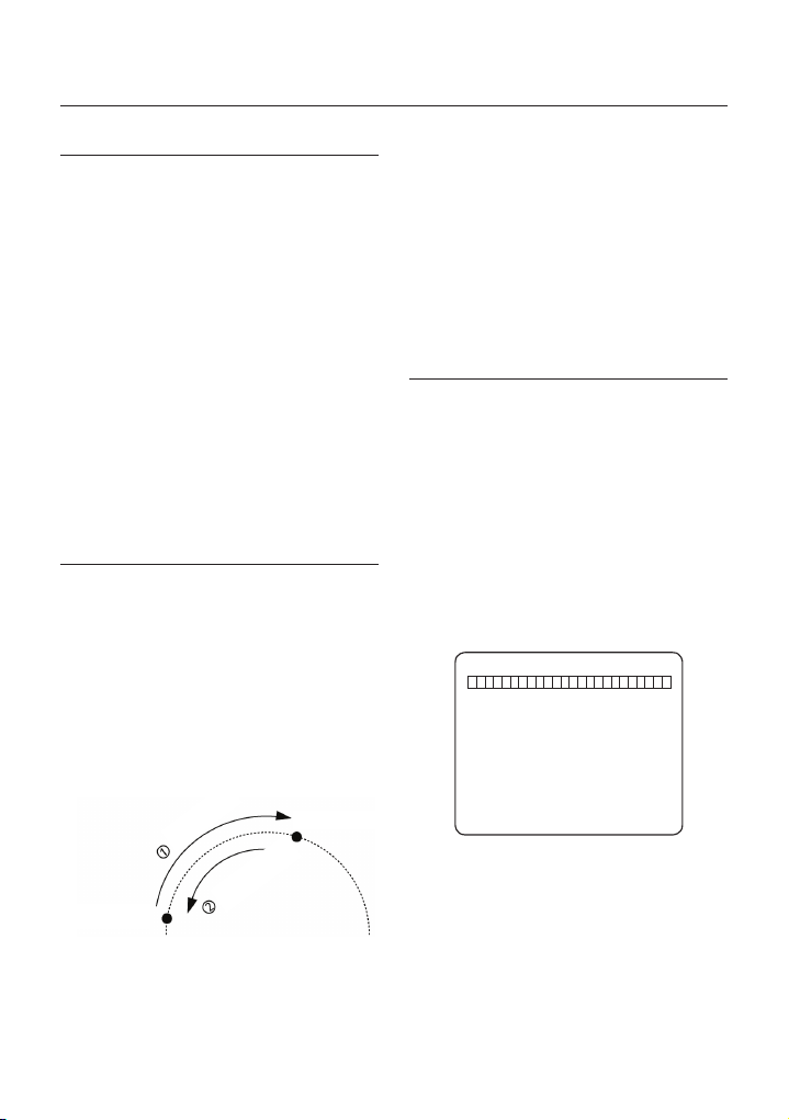
Fonctionnement
PRÉRÉG.
Fonction
•
Total de 127 positions pouvant être stockées comme des
préréglages.
Il est possible d’attribuer un numéro de préréglage compris
entre 1 et 128. Il est à noter que le préréglage « 95 » est
réservé au lancement du menu Affi chage à l’écran.
Les caractéristiques de la caméra (par ex., Balance des
blancs, Exposition auto) peuvent être confi gurées de
manière indépendante pour chaque préréglage puis
ajustées via le menu Affi chage à l’écran. Quatre sorties
de relais peuvent être activées conjointement avec un
Préréglage.
Défi nir un préréglage
•
<Déf. Prér.> [1~128]
Exécuter un préréglage
•
<Aller dans les Prérég.> [1~128]
Supprimer un préréglage
•
Pour supprimer un préréglage, utilisez le menu OSD.
PANORAMIQUE AUTOMATIQUE
Fonction
•
Grâce à la fonction Panoramique automatique, vous
pouvez faire en sorte que la caméra se déplace
alternativement entre 2 positions préréglées.
Lorsque la fonction Panoramique automatique est en
cours d’utilisation, la caméra se déplace depuis la position
préréglée désignée comme le premier point vers la position
préréglée désignée comme le second point, dans le sens
des aiguilles d’une montre. Puis la caméra se déplace
depuis la position préréglée désignée comme le second
point, vers la position préréglée désignée comme le
premier point, dans le sens inverse.
Sens des aiguilles
d’une montre
Sens inverse des
Premier préréglage
Dans le cas où la première et la seconde positions
préréglées sont les mêmes, la caméra tourne sur son
axe dans le sens des aiguilles d’une montre en suivant
un angle de 360°, puis revient à sa position initiale dans
le sens inverse des aiguilles d’une montre.
La vitesse de rotation peut aller de 1°/s à 180°/s.
22 – 10X MINI SMART DOME CAMERA
aiguilles d’une montre
Second préréglage
Réglage du Panoramique automatique
•
Pour régler le Panoramique automatique, utilisez le
menu OSD.
•
Exécution du Panoramique automatique
Méthode 1) <Activ. Pan Auto> [N° Pan Auto] [Entrée]
Méthode 2) <<Aller dans les Prérég.> [N° Pan Auto+140]
ex. : Exécution Pan auto 2 : <Aller dans les Prérég.> [142]
•
Supprimer le Panoramique automatique
Pour supprimer le Panoramique automatique, utilisez le
menu OSD.
MODÈLE
•
Fonction
La fonction Modèle permet de mémoriser le chemin
(trajectoire courbe généralement) créé par le contrôleur
de clavier. En exécutant le modèle, la trajectoire
mémorisée peut être reproduite à l’identique selon les
besoins.
4 modèles sont disponibles et jusqu’à 1200 commandes de
communication peuvent être enregistrées dans un modèle.
•
Réglage du modèle
Le modèle peut être créé avec l’une des deux
méthodes suivantes.
Méthode 1) <Rég. Modèle> [N° Modèle]
–
L’écran de modifi cation de modèle s’affi che comme
montré ci-dessous.
MODIF MODÈLE 1
[PRÈS:SAUVEG/LOIN:ANNUL]
–
Il est possible d’enregistrer dans un modèle un mouvement
effectué avec le joystick ou un mouvement préréglé.
La taille de la mémoire restante s’affi che dans la barre
–
de progression.
Pour enregistrer l’enregistrement, appuyez sur la touche
–
PRÈS ; pour l’annuler, appuyez sur la touche LOIN.
Méthode 2) Utilisation du menu OSD : Consultez le
chapitre « Utilisation du menu OSD ».
0/0/X1/N

Fonctionnement
Exécution du modèle
•
Méthode 1) <Exéc. Modèle> [N° Modèle]
ex.) Exécution du modèle 2 : <Exéc. Modèle> [2]
Méthode 2) <Aller dans les Prérég.> [N° Modèle+130]
ex.) Exécution du modèle 2 : <Aller dans les Prérég.> [132]
•
Suppression du modèle
Utilisez le menu OSD pour supprimer un modèle.
Quand le MODÈLE est enregistré/exécuté, le PAN/
TILT (PANORAMIQUE/HORIZONTAL-VERTICAL)
s’effectue en mode FLIP AUTO OFF.
BALAYAGE
•
Fonction
La fonction Balayage permet de lancer la séquence des
fonctions Prérég., Modèle et/ou Panoramiques automatiques. 8
balayages peuvent être enregistrés. Chaque balayage peut avoir
jusqu’à 20 entités d’action qui peuvent être un préréglage, un
modèle ou un panoramique automatique. Le temps de passage
est l’intervalle de temps entre les actions. Il est réglable via le
menu. Par ailleurs, il existe un numéro d’option qui permet
de confi gurer la vitesse de préréglage ainsi que le nombre de
répétitions relatives aux fonctions Modèle et Pan auto.
Temps de passage
•
Réglage du balayage
Modèle 5Préréglage 1
20 entités maxi.
Utilisez le menu OSD pour créer un balayage.
•
Exécution du balayage
Méthode 1) <Exéc. Balay.> [N° Balay.]
ex.) Exécution du balayage 2 : <Exéc. Balay.> [2]
Méthode 2) <Exécuter un préréglage> [N° Balay.+150]
ex.) Exécution du balayage 2 : <Exécuter un préréglage> [152]
Suppression d’un balayage
•
Utilisez le menu OSD pour supprimer un balayage.
PROGRAMMATION
Fonction
•
La fonction Programmation permet de lancer une fonction
particulière telle que Prérég., Panoramique automatique,
Balay., Modèle, Accueil à un jour et une heure donnés. Si vous
confi gurez par exemple une règle pour le mardi 9h00 avec le
Préréglage 1 (Portail principal), la caméra s’orientera vers le
Balayage 5
portail principal tous les mardis à 9h00. Si vous choisissez Jour
de semaine, la caméra s’orientera vers le portail principal tous
les jours, sauf le week-end.
Notez que grâce à l’heure en temps réel, les données
concernant l’heure seront conservées même en cas de panne
de courant. Le réglage initial de la date et de l’heure est donc
essentiel à une bonne utilisation de la fonction Programmation.
Réglage de la Programmation
•
Utilisez le menu OSD pour créer une programmation.
Exécution d’une programmation
•
Utilisez le menu OSD dans Activer maître programmation
Suppression d’une programmation
•
Utilisez le menu OSD pour supprimer une programmation.
AUTRES FONCTIONS
Verrouil. prér.
•
Cette fonction est conçue pour protéger les données
préréglées contre toute suppression non autorisée. Si la
fonction Verrouil. prér. est défi nie sur ON, la commande
d’enregistrement des préréglages par la touche de raccourci
est désactivé, tandis que l’enregistrement via le menu OSD
reste possible.
•
Mise sous tension
Cette fonction permet de revenir à la dernière action exécutée
par l’appareil avant que celui-ci ne soit éteint. La plupart des
actions telles que Prérég., Modèle, Panoramique automatique et
Balay. sont disponibles avec cette fonction mais il est impossible
de revenir aux actions faisant appel à l’image par image.
•
Flip auto
Si l’angle horizontal/vertical arrive au bout de l’orbite tilt (90°),
la caméra du module zoom continue son déplacement dans
la direction horizontale/verticale opposée (180°) pour continuer
à suivre les cibles. Dès que la caméra du module zoom
dépasse l’extrémité de la direction horizontale/verticale (90°),
les images sont inversées automatiquement et la lettre
apparaît à l’écran. Si cette fonction est désactivée, la plage du
mouvement horizontal/vertical s’étend de 0 à 90°.
•
Action parc.
Cette fonction permet de placer automatiquement la caméra
dans une position défi nie si l’opérateur n’effectue aucune action
pendant un certain laps de temps. Vous pouvez défi nir l’intervalle
de temps de la fonction Parc. entre 1 minute et 4 heures.
•
Alarm Input (Entrée alarme)
2 entrées d’alarme sont utilisées. Si un capteur externe est
activé, la caméra peut être réglée pour se déplacer vers la
position Prérég. Notez que, dans le cas où plusieurs capteurs
sont activés, c’est l’entrée d’alarme la plus récente qui est
effi cace.
F
Français – 23
FRE

Fonctionnement
Zone Masque de confi dentialité
•
Afi n de préserver la vie privée, 4 masques de confi dentialité
peuvent être créés dans une position aléatoire pour cacher
certains objets tels que fenêtres, magasins ou maisons privées.
Grâce au système de coordonnées sphériques, la fonction
Zone Masque de confi dentialité est très effi cace.
Confi guration de l’image GÉNÉRAL/SPÉCIAL
•
BAL BLANCS (Balance des blancs) et EXP AUTO (exposition
automatique) peuvent être réglées indépendamment pour
chaque préréglage. Il existe deux modes : Général et Spécial.
Le mode Général signifi e que la fonction BAL BLANCS ou EXP
AUTO peut être réglée entièrement et simultanément pour tous
les préréglages dans le menu « CONFIG ZOOM CAMÉRA ».
Le mode Spécial signifi e que la fonction BAL BLANCS ou EXP
AUTO peut être réglée indépendamment ou séparément pour
chaque réglage dans chaque menu de confi guration préréglée.
Chaque valeur BAL BLANCS/EXP AUTO Spécial doit être activée
lorsque la caméra arrive à l’emplacement préréglé correspondant.
Pendant le fonctionnement image par image, la valeur BAL
BLANCS/EXP AUTO Général doit être appliquée. La valeur
BAL BLANCS/EXP AUTO Spécial ne sera pas modifi ée même
si la valeur BAL BLANCS/EXP AUTO Général est modifi ée.
•
Mise au point semi-automatique
Ce mode permet de changer automatiquement de mode
de mise au point, opération par opération. Le mode de
mise au point manuel est sélectionné durant l’opération
de préréglage et le mode de mise au point automatique
est réactivé dès le début du maniement de la molette.
Durant l’action de préréglage, ce n’est pas la fonction de
mise au point automatique mais les données stockées
de la mise au point manuelle, dès lors qu’elles ont été
créées, qui sont appliquées lorsque la caméra passe en
mode préréglage. Ceci est utile pour obtenir rapidement
des images à la mise au point réussie.
AFFICHAGE OSD SUR L’ÉCRAN
PRINCIPAL
Préréglage étiquette 1
Date/Heure
ID caméra
24 – 10X MINI SMART DOME CAMERA
ÉTIQUETTE12345 PRÉRÉG1
Flip image
ID caméra
Informations P/T/Z
Titre action
Température
Informations
d’alarme
Informations P/T/Z
•
Angle Pan/Horizontal-Vertical actuel en degrés,
agrandissement au zoom et direction.
ID caméra
•
ID caméra actuel (adresse).
Titre action
•
Les exemples donnés ci-dessous sont des titres
d’action possibles, avec leur signifi cation.
« DÉF. PRÉR. ××× »
« PRÉRÉG ××× » Lorsque la caméra atteint le
« MODÈLE × » Lorsque le Modèle × est en
« AUP×/PRÉRÉG ××× »
« NON DÉF. »
•
Étiquette prérég.
Lorsque le Prérégl ××× est
stocké
Prérégl ×××
cours d’exécution
Lorsque Pan auto x est en
cours d’exécution
Lorsqu’une fonction indéfi nie
est appelée pour être exécutée
L’étiquette enregistrée pour un préréglage spécifi que.
•
Informations d’alarme
Ces informations affi chent l’état actuel de l’entrée alarme.
La lettre « I » se rapporte à l’entrée et la lettre « O » à
la sortie. Si l’état d’une entrée est ON, le numéro de
l’entrée s’affi che. Si l’état d’une entrée est OFF, « - »
s’affi che. De la même façon « O :1 » signifi e que la sortie
1 est ON, « O-:- » qu’elle est OFF.
Exemple) Lorsque le point 2 des entrées est ON et que
la sortie 1 est On, alors l’OSD affi che :
I:-2 0:1
•
Flip image
Montre que les images sont actuellement inversées par
la fonction Flip auto.
•
Température
Température actuelle : « C » et « F » signifi ent
respectivement Celsius et Fahrenheit.
Date/Heure
•
Affi che la date et l’heure actuelles.

Utilisation du menu OSD
FONCTIONNEMENT GÉNÉRAL
DU MENU
Les éléments du menu encadrés par < > ont toujours
•
un sous-menu.
Pour accéder au sous-menu depuis n’importe quel
•
niveau de menu, appuyez sur PRÈS ou sur la touche
ENTRÉE.
•
Pour accéder au menu du niveau supérieur, appuyez
sur la touche LOIN.
Pour vous déplacer d’élément en élément dans le
•
menu, utilisez le joystick dans le menu Haut/Bas ou
Gauche/Droite.
Pour modifi er la valeur d’un élément, utilisez Haut/Bas
•
du joystick dans le contrôleur.
Appuyez sur PRÈS ou sur la touche ENTRÉE pour
•
enregistrer les valeurs et sur la touche LOIN pour les
annuler.
MENU PRINCIPAL
MENU RACINE
<INFO SYSTEME>
<CONFIG AFFICHAGE>
<CONFIG. MOUVEMENT>
<CONFIG FONCTION>
<CONFIG CAMÉRA>
<CONFIGURATION SYSTÈME>
<INITIALISER SYSTÈME>
QUIT.
•
INFO SYSTÈME
Affi che les informations système telles que la version du
micrologiciel actuel et les réglages de communication.
•
CONFIG AFFICHAGE
Active/Désactive l’affi chage OSD sur l’écran principal.
CONFIG. MOUVEMENT
•
Confi guration des réglages liés au mouvement
CONFIG FONCTION
•
Confi guration des diverses fonctions telles que Prérég.,
Panoramique auto, Modèle, Balay. et Programmation.
CONFIG CAMÉRA
•
Confi guration des fonctions et des données liées à la caméra
CONFIGURATION SYSTÈME
•
Confi guration du système de base.
INITIALISER SYSTÈME
•
Initialise la confi guration système et règle toutes les
données selon la confi guration par défaut.
INFO SYSTÈME
INFO SYSTEME
V. MICROLOGIC. 1.0250
SYST COULEURS NTSC
PROTOCOLE SAMSUNG
DÉBIT EN BAUDS 9600
ADRESSE 255
RETOUR
QUIT.
V. MICROLOGICIEL
•
Affi che la version actuelle du micrologiciel de la caméra.
SYST. COULEURS
•
Affi che le système de vidéo analogue actuel de la caméra.
PROTOCOLE Affi che le protocole actuel pour le
•
DÉBIT EN BAUDS Affi che le débit en bauds du
•
ADRESSE Affi che l’ID caméra actuel pour le
•
contrôle PTZ
contrôle PTZ.
contrôle PTZ
CONFIG AFFICHAGE
CONFIG AFFICHAGE
ID CAMÉRA ON
INFO PTZ AUTO
TITRE ACTION AUTO
ÉTIQUETTE PRÉRÉG.
E/S ALARME AUTO
DATE/HEURE ON
<ZONE CONFIDENT.>
TEMPÉRATURE CELSIUS
RETOUR
QUIT.
Ce menu défi nit l’activation/désactivation de l’affi chage
OSD sur l’écran principal. Si un élément est en mode
AUTO, il est affi ché seulement quand sa valeur est
modifi ée.
•
ID CAMÉRA [ON/OFF]
•
INFO PTZ [ON/OFF/AUTO]
•
TITRE ACTION [ON/OFF/AUTO]
•
ÉTIQUETTE PRÉRÉG. [ON/OFF/AUTO]
•
E/S ALARME [ON/OFF/AUTO]
•
DATE/HEURE [ON/OFF]
•
TEMPÉRATURE
AUTO
[CELSIUS/FAHRENHEIT/OFF]
Français – 25
FRE

Utilisation du menu OSD
❖
RÉGLAGE DE LA ZONE MASQUE
DE CONFIDENTIALITÉ
ZONE CONFIDENT.
N° MASQUE 1
NON DÉF.
AFFICHAGE OFF
EFFACER MASQ. ANNULER
<ÉDITER MASQUE>
RETOUR
QUIT.
Sélectionnez une zone dans l’image à masquer.
N° MASQUE [1 à 4]
•
Sélectionnez le numéro de masque. Si le masque
sélectionné possède déjà des données, la caméra
se place selon le réglage effectué. Sinon, NON DÉF
s’affi che sous le « N° masque ».
AFFICHER [ON/OFF]
•
Défi nit si la caméra applique ou non des masques sur
l’image.
EFFACER MASQ. [ANNULER/OK]
•
Efface les données dans le N° de masque sélectionné.
Confi guration de la zone de confi dentialité
❖
ÉDITER MASQUE 1
DÉPLACER VERS POS. CIBLE
[PRÈS:SÉLECT/LOIN:ANNUL]
Déplace la caméra vers la zone à masquer. Puis le menu
pour l’ajustement de la taille du masque s’affi che.
26 – 10X MINI SMART DOME CAMERA
0/0/x1/N
Ajustement de la taille de la zone de
confi dentialité
ÉDITER MASQUE 1
ÅÆ:
RÉGLER LARG. MASQUE
[
ÇÈ:
RÉGLER HAUT. MASQUE
[
[PRÈS:SÉLECT/LOIN:ANNUL]
Ajustez la taille du masque. Utilisez le joystick ou les
fl èches pour ajuster la taille du masque.
ÅÆ(Gauche/Droit) Ajuste la largeur du masque.
•
ÇÈ
(Haut/Bas) Ajuste la hauteur du masque.
•
Il est à noter que durant un contrôle PAN/TILT, comme
par exemple en actionnant la molette, l’objet situé
derrière le masque de confi dentialité peut être dévoilé
au bout d’un court moment.
Pour cacher complètement une zone défi nie
indépendamment des mouvements PT grande vitesse,
il est recommandé de choisir une taille de masque
supérieure de 20% à la taille de la cible de départ.
CONFIG. MOUVEMENT
CONFIG. MOUVEMENT
VERROUIL. PRÉR. ON
MISE SS TENSION ON
FLIP AUTO ON
VIT MAX IM.P.IM 140/S
DIRECT. IM.P.IM NORMAL
GELER EN PRÉREG OFF
<CONFIG ACTION PARC.>
<CONFIG ENTRÉE ALARME>
RETOUR
QUIT.
Confi gure les fonctions générales des mouvements
Panoramique/Horizontal-vertical.
•
VERROUIL. PRÉR. [ON/OFF]
Cette fonction permet de protéger les données de
préréglage contre tout risque d’écrasement.
Lorsque la fonction Verrouil. prér. est spécifi ée sur ON,
il est impossible de créer et de supprimer les options
Prérég, Pan auto, Modèle et Balay. Celles-ci peuvent
uniquement être exécutées. Pour créer et supprimer
ces fonctions, il faut utiliser le menu Affi chage à l’écran.
]
]

Utilisation du menu OSD
MISE SOUS TENSION [ON/OFF]
•
Reportez-vous à la section « Autres fonctions ».
•
FLIP AUTO [ON/OFF]
Reportez-vous à la section « Autres fonctions ».
•
VIT MAX IM.P.IM [2°/s ~360°/s]
Règle la molette en vitesse maximale. La vitesse
de la molette est inversement proportionnelle à
l’agrandissement de zoom. Plus le grossissement
du zoom est important, plus la vitesse Pan/tilt
(Panoramique/Horizontal-Vertical) est basse.
DIRECT. IM.P.IM [INVERS./NORMAL]
•
Si vous optez pour le réglage « Normal », l’affi chage
à l’écran se déplace dans la même direction que
l’orientation horizontale/verticale image par image. Si vous
choisissez « Inverse », l’affi chage sur l’écran est inversé.
•
GEL EN PRÉRÉG. [ON/OFF]
La caméra gèle l’image du point de départ du
mouvement préréglé. La caméra continue d’affi cher
l’image du point de départ pendant qu’elle effectue le
mouvement préréglé et n’affi che pas les images qu’elle
obtient pendant ce mouvement. Dès que la caméra
s’arrête au point de fi n préréglé, la caméra commence à
affi cher en direct les images du point de fi n préréglé.
La disponibilité de cette fonction peut varier selon les
modèles.
Confi g Action parc.
❖
CONFIG ACTION PARC.
ACTIVER PARC. OFF
TEMPS ATT. 00:10:00
ACTION PARC. ACCUEIL
RETOUR
QUIT.
Si la fonction Activer parc. est défi nie sur ON, la caméra
effectue automatiquement les fonctions assignées si aucune
commande PTZ n’est lancée pendant le « Temps att. ».
ACTIVER PARC. [ON/OFF]
•
TEMPS ATT. [5 secondes à 4 heures]
•
L’heure s’affi che au format « hh:mm:ss » et peut être
réglée par incrément d’1 minute.
•
ACTION PARC
Exemple : si ACCUEIL est sélectionné pour Action
[
ACCUEIL/PRÉRÉG./MODÈLE/
PAN AUTO/BALAY.
parc., la caméra reviendra à la position
d’accueil lorsqu’aucune commande PTZ
n’est lancé pendant le « Temps att. ».
]
Confi g entrée alarme
❖
CONFIG ENTRÉE ALARME
ALARME1 O.N PRÉRÉG1
ALARME2 F.N NON UTIL.
RETOUR
QUIT.
Faites correspondre le capteur alarme avec une
des positions préréglées. Si un capteur externe est
activé, la caméra se déplace vers la position préréglée
correspondante lorsque cet élément est prédéfi ni.
TYPE ALARME
•
[OUVERTURE norm.(O.N) / FERMETURE norm(F.N)]
Défi nit le type d’entrée du capteur.
ACTION ALARME
•
[NON UTIL./ACCUEIL/PRÉRÉG. 1~128/PANAUTO
1~8, MODÈLE1~4, BALAY. 1~4]
Pour chaque entrée alarme, vous pouvez assigner
des fonctions de neutralisation (Prérég., Pan auto,
Modèle, Balay.).
CONFIG FONCTION
CONFIG FONCTION
<CONFIG. PRÉRÉGLÉE>
<CONFIG. PAN AUTO>
<CONFIG MODÈLE>
<CONFIG. BALAYAGE>
<CONFIG PROGRAMMATION>
RETOUR
QUIT.
Confi gurez 5 fonctions spéciales à l’aide de ce menu.
•
CONFIG. PRÉRÉGLÉE
127 préréglages allant du numéro 1 au numéro 128
peuvent être assignés, à l’exception du numéro 95 qui
est réservé au menu.
•
CONFIG. PAN AUTO
8 pans auto sont disponibles, permettant de déplacer la
caméra lentement entre deux points préréglés.
Français – 27
FRE

Utilisation du menu OSD
CONFIG MODÈLE
•
4 modèles peuvent être enregistrés dans le dôme.
Avec cette fonction, les données de chemin créées par
le mouvement manuel du joystick sont enregistrées et
vous pouvez les rejouer automatiquement quand cela
est nécessaire.
CONFIG. BALAYAGE
•
Un maximum de 8 balayages peut être défi ni.
Lors d’un balayage, 20 entités peuvent être assignées
à partir de n’importe quelle combinaison de Prérég./
Panoramique automatique/Modèle. Si vous lancez
un balayage, la caméra exécutera chaque entrée
successivement.
CONFIG PROGRAMMATION
•
7 règles de programmation peuvent être attribuées
pour chaque jour et chaque heure. Des actions
appropriées (Accueil, Prérég., Balayage, Modèle et
Pan auto) peuvent être défi nies pour chaque règle. Il
est également possible d’utiliser Jour de semaine et
Weekend dans une règle pour la simplifi er.
CONFIG. PRÉRÉGLÉE
CONFIG. PRÉRÉGLÉE
N° PRÉRÉGLAGE 1
<MODIFIER SCÈNE>
ÉTIQUET.
>
<
EFF. PRÉRÉG. ANNULER
RÉGLAGE CAM GÉNÉRAL
SORTIE ALARME ----
RETOUR
QUIT.
NORTH GATE
EFFACER LE PRÉRÉGLAGE [ANNULER/OK]
•
Supprimez les données préréglées actuelles
RÉGLAGE CAM [GÉNÉRAL/SPÉCIAL]
•
BAL BLANCS (Balance des blancs) et EXP AUTO
(exposition automatique) peuvent être réglées
indépendamment pour chaque préréglage. Il existe
deux modes : Général et Spécial. Le mode Général
signifi e que la fonction BAL BLANCS ou EXP AUTO
peut être réglée entièrement et simultanément pour tous
les préréglages dans le menu « CONFIG CAMÉRA ».
Le mode Spécial signifi e que la fonction BAL BLANCS
ou EXP AUTO peut être réglée indépendamment
ou séparément pour chaque réglage dans chaque
menu de confi guration préréglée. Chaque valeur BAL
BLANCS/EXP AUTO Spécial doit être activée lorsque la
caméra arrive à l’emplacement préréglé correspondant.
Pendant le fonctionnement image par image, la valeur
BAL BLANCS/EXP AUTO Général doit être appliquée.
La valeur BAL BLANCS/EXP AUTO Spécial ne sera pas
modifi ée même si la valeur BAL BLANCS/EXP AUTO
Général est modifi ée. Si « Spécial » est sélectionné, le
menu de réglage BAL BLANCS/EXP AUTO s’affi che à
l’écran. La valeur par défaut est GÉNÉRAL.
SORTIE ALARME
•
La sortie relais peut être liée à la fonction Exé préreg.
Le caractère « - » indique la désactivation et le numéro «
1 » représentant chaque bit signifi e ON (Activation).
Ex) Lorsque ceci est réglé sur « 1 », le relais de sortie
est activé (ON) dès que vous appelez ce préréglage.
Modifi er la scène préréglée
❖
MODIFIER SCÈNE - PRÉRÉG 1
•
N° PRÉRÉGLAGE [1 à 128]
Si un préréglage sélectionné est déjà défi ni, la
caméra se déplace sur la position prédéfi nie et les
caractéristiques préréglées telles que Étiquet. et
Sorties de relais s’affi chent à l’écran. Si le préréglage
sélectionné n’est pas défi ni, « NON DÉF. » s’affi che à
l’écran.
•
MODIFIER LA SCÈNE PRÉRÉGLÉE
Redéfi nissez la position de la scène préréglée actuelle
(c.-à-d. PTZ).
•
MODIFIER L’ÉTIQUETTE PRÉRÉGLÉE
Permet de modifi er l’étiquette à affi cher à l’écran lors
de l’activation du préréglage. Un maximum de 10
caractères alphabétiques est autorisé.
28 – 10X MINI SMART DOME CAMERA
DÉPLACER VERS POS. CIBLE
[PRÈS:SÉLECT/LOIN:ANNUL]
① À l’aide du joystick, déplacez la caméra sur la
position souhaitée.
② En appuyant sur PRÈS ou sur la touche ENTRÉE,
vous sauvegardez les données PTZ en cours.
③ Appuyez sur la touche LOIN pour annuler.
0/0/x1/N

Modifi er l’étiquette préréglée
❖
Utilisation du menu OSD
CONFIG. PAN AUTO
MODIF. ÉTIQUET. - PRÉRÉG 1
[█ ]
--------- 1234567890 OK
ABCDEFGHIJ ANNULER
KLMNOPQRST
UVWXYZabcd
efghijklmn
opqrstuvwx
yz<>-/:.
----------
①
Permet de modifi er l’étiquette à affi cher à l’écran
lorsque la caméra atteint les préréglages. Dans
le menu Modifi er l’étiquette, un rectangle inversé
correspond au curseur. Une fois la sélection des
lettres terminée, le curseur se déplace sur le
chiffre suivant.
[█ ]
Position actuelle du curseur
② En utilisant les fl èches Gauche/Droite/Haut/Bas
du joystick, accédez au caractère souhaité dans
le jeu de caractères. Pour choisir ce caractère,
appuyez sur PRÈS ou sur la touche ENTRÉE.
--------- 1234567890
ABCDEFGHIJ
KLMNOPQRST
UVWXYZabcd
efghijklmn
opqrstuvwx
yz<>-/:.
----------
Caractère espace arrièreCaractère espace.
Pour insérer un espace, utilisez le caractère espace
(“ ”) . Si vous souhaitez supprimer un caractère,
utilisez le caractère espace arrière ().
③ Lorsque vous avez terminé la modifi cation de
l’étiquette, déplacez le curseur sur « OK » et
appuyez sur PRÈS ou sur la touche ENTRÉE
pour sauvegarder l’étiquette ainsi complétée. Pour
abandonner les changements en cours, déplacez
le curseur sur « Annuler » et appuyez sur PRÈS ou
sur la touche ENTRÉE.
CONFIG. PAN AUTO
N° PAN AUTO 1
ÈRE
POS. NON UTIL.
1
ÈRE
POS. NON UTIL.
2
VIT PAN AUTO 30/S
EFF PAN AUTO ANNULER
RETOUR
QUIT.
NUMÉRO PAN AUTO [1 à 8]
•
Permet de sélectionner le numéro Pan auto à modifi er.
Si la fonction Panoramique automatique sélectionnée
n’a pas été défi nie, « NON UTIL. » s’affi che en première
et deuxième positions.
1ÈRE POSITION [PRÉRÉG. 1 à 128]
•
2ÈME POSITION
•
Confi gurez les deux positions de la fonction Panoramique
automatique. Si un préréglage sélectionné n’est pas défi ni,
« NON DÉF. » s’affi che comme indiqué ci-dessous.
CONFIG. PAN AUTO
N° PAN AUTO 1
ÈRE
POS. PRÉRÉG5
1
ÈRE
POS. NON UTIL.
2
NON DÉF.
Lorsque la fonction Panoramique automatique est
en cours d’utilisation, la caméra se déplace depuis la
position préréglée désignée comme le premier point
vers la position préréglée désignée comme le second
point, dans le sens des aiguilles d’une montre. Puis
la caméra se déplace depuis la position préréglée
désignée comme le second point, vers la position
préréglée désignée comme le premier point, dans le
sens inverse.
Dans le cas où la première et la seconde positions
préréglées sont les mêmes, la caméra tourne sur son
axe dans le sens des aiguilles d’une montre en suivant
un angle de 360°, puis elle revient à sa position initiale
dans le sens inverse des aiguilles d’une montre.
VIT PAN AUTO [1°/s à 180°/s]
•
Permet de régler la vitesse Pan Auto de 1°/s à 180°/s.
EFF PAN AUTO [ANNULER/OK]
•
Permet d’effacer les données Pan auto actuelles.
Français – 29
FRE

Utilisation du menu OSD
CONFIG MODÈLE
CONFIG MODÈLE
N° MODÈLE 1
NON DÉF.
EFF MODÈLE ANNULER
<MODIF MODÈLE>
RETOUR
QUIT.
N° MODÈLE [1 à 4]
•
Permet de sélectionner le numéro de modèle à modifi er.
Si un numéro de modèle sélectionné n’est pas défi ni, «
NON DÉF. » s’affi che sous celui-ci.
EFF MODÈLE [ANNULER/OK]
•
Permet d’effacer les données du modèle actuel.
MODIF MODÈLE
•
Permet de démarrer la modifi cation du modèle.
Modif modèle
❖
① Grâce au joystick, accédez à la position de
départ à l’aide du zoom approprié. Pour lancer
l’enregistrement du modèle, appuyez sur PRÈS
ou sur la touche ENTRÉE. Pour quitter ce menu,
appuyez sur la touche LOIN.
MODIF MODÈLE 1
RETOUR DÉPART
[PRÈS:DÉP./LOIN:ANNULER]
② Déplacez la caméra à l’aide du joystick du
contrôleur ou lancez la fonction préréglée pour
mémoriser la trajectoire (généralement incurvée)
dans un modèle sélectionné. La taille globale
de la mémoire et la taille de la mémoire restante
s’affi chent sous forme de barre. Jusqu’à 1200
commandes de communication peuvent être
enregistrées dans un modèle.
30 – 10X MINI SMART DOME CAMERA
0/0/x1/N
MODIF MODÈLE 1
[PRÈS:SAUVEG/LOIN:ANNUL]
③
Pour enregistrer les données et quitter l’application,
appuyez sur PRÈS ou sur la touche ENTRÉE. Pour
annuler l’enregistrement et supprimer les données
enregistrées, appuyez sur la touche LOIN.
0/0/X1/N
CONFIG. BALAYAGE
CONFIG. BALAYAGE
N° BALAYAGE 1
NON DÉF.
EFF BALAYAGE ANNULER
<MODIFIER BALAYAGE>
RETOUR
QUIT.
N° BALAYAGE [1 à 8]
•
Permet de sélectionner le numéro de balayage à modifi er.
Si un numéro de balayage sélectionné n’est pas défi ni, «
NON DÉF. » s’affi che sous celui-ci.
•
EFF BALAYAGE [ANNULER/OK]
Permet d’effacer les données du balayage actuel.
•
MODIFIER BALAYAGE Permet de démarrer la
Modifi er balayage
❖
① Appuyez sur PRÈS ou sur la touche ENTRÉE
dans la liste « N° » pour lancer la confi guration de
la fonction Balay.
MODIFIER BALAYAGE 1
N° ACTION N° PASS. OPT
1 AUCUN
2 AUCUN
3 AUCUN
4 AUCUN
5 AUCUN
SAUVEG
ANNULER [PRÈS:MODIF]
modifi cation du balayage.

Utilisation du menu OSD
②
Notez qu’un maximum de 20 fonctions est autorisé
lors d’un balayage. Déplacez le curseur vers le haut/
bas et appuyez sur PRÈS ou sur la touche ENTRÉE
pour effectuer la confi guration.
MODIFIER BALAYAGE 1
N° ACTION N° PASS. OPT
1 AUCUN
2 AUCUN
3 AUCUN
4 AUCUN
5 AUCUN
SAUVEG [PRÈS:MODIF ACT]
ANNULER [LOIN:FIN MODIF]
③ Confi gurez l’action, le temps de passage et
l’option. Notez que l’élément sélectionné s’affi che
à l’envers. Déplacez le curseur vers la droite/
gauche pour sélectionner les éléments et vers le
haut/bas pour modifi er la valeur.
MODIFIER BALAYAGE 1
N° ACTION N° PASS. OPT
1 AUCUN
2 AUCUN
3 AUCUN
4 AUCUN
5 AUCUN
SAUVEG [ÅÆ:DÉPL. CURS.]
ANNULER [ÇÈ:MODIF. VAL.]
N° ACTION
•
[AUCUN/PRÉRÉG./PANORAMIQUE
AUTOMATIQUE/MODÈLE]
PASS. [1 seconde à 4 minutes]
•
Permet de confi gurer le temps de passage entre
les fonctions.
OPT
•
Option. Représente la vitesse préréglée (2 à 360)
lorsque le préréglage est sélectionné. Elle doit
correspondre au nombre de répétitions (1 à 255)
lorsque Modèle ou Panoramique automatique
est sélectionné pour Action.
④ Confi gurez les éléments tels que Action, N°, Pass.
et OPT.
MODIFIER BALAYAGE 1
N° ACTION N° PASS. OPT
1 PRÉRÉG 1 00:03 360
2 AUCUN
3 AUCUN
4 AUCUN
5 AUCUN
SAUVEG [ÅÆ:DÉPL. CURS.]
ANNULER [ÇÈ:MODIF. VAL.]
⑤ Une fois que vous avez terminé de confi gurer
une Action, appuyez sur PRÈS ou sur la touche
ENTRÉE pour accéder au menu de niveau
supérieur suivant (étape ②). Déplacez le curseur
vers le Haut/Bas pour sélectionner le numéro
d’action et répétez les étapes ② à ④ pour modifi er
le balayage sélectionné.
MODIFIER BALAYAGE 1
N° ACTION N° PASS. OPT
1 PRÉRÉG 1 00:03 360
2 AUCUN
3 AUCUN
4 AUCUN
5 AUCUN
SAUVEG [PRÈS:MODIF ACT]
ANNULER [LOIN:FIN MODIF]
⑥ Une fois le réglage de toutes les actions terminé,
appuyez sur la touche LOIN pour quitter
l’application. Déplacez ensuite le curseur sur «
SAUVEG ». Appuyez sur PRÈS ou sur la touche
ENTRÉE pour sauvegarder les données.
MODIFIER BALAYAGE 1
N° ACTION N° PASS. OPT
1 PRÉRÉG 1 00:03 360
2 AUCUN
3 AUCUN
4 AUCUN
5 AUCUN
SAUVEG
ANNULER
FRE
Français – 31
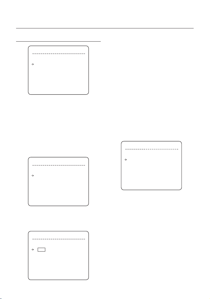
Utilisation du menu OSD
CONFIG PROGRAMMATION
CONFIG PROGRAMMATION
ACTIVER MAÎTRE ON
J. HEURE ACT N° ON
1 NON DÉF.
2 NON DÉF.
3 NON DÉF.
4 NON DÉF.
5 NON DÉF.
6 NON DÉF.
7 NON DÉF.
RETOUR
ACTIVER MAÎTRE [ON/OFF]
•
Choisissez d’activer ou non la fonction de programmation.
EFFACER LA PROGRAMMATION [ANNULER/OK]
•
Effacez toutes les données du menu actuel.
MODIFIER LA PROGRAMMATION
•
Permet de lancer la modifi cation de la programmation.
Modifi er la programmation
❖
① Déplacez le curseur sur le numéro à l’aide des
touches vers le haut/bas et appuyez sur la touche
PRÈS (Entrée) pour effectuer une modifi cation.
CONFIG PROGRAMMATION
ACTIVER MAÎTRE ON
J. HEURE ACT N° ON
1 NON DÉF.
2 NON DÉF.
3 NON DÉF.
4 NON DÉF.
5 NON DÉF.
6 NON DÉF.
7 NON DÉF.
RETOUR
② Chaque champ peut être sélectionné à l’aide
des touches droite/gauche et les valeurs dans
les champs peuvent être modifi ées à l’aide des
touches haut/bas.
CONFIG PROGRAMMATION
ACTIVER MAÎTRE ON
J. HEURE ACT N° ON
1 LUN 00:00 ACC OFF
2 NON DÉF.
3 NON DÉF.
4 NON DÉF.
5 NON DÉF.
6 NON DÉF.
7 NON DÉF.
RETOUR
Signifi cation de chaque valeur :
J. Jours : LUN MAR MER JEU
VEN SAM DIM
WKD: jour de la semaine
TT: tous les jours
HEURE Format 24 heures
ACT PRR (préréglage), PAU (pan auto),
MOD (modèle), BAL (balayage), ACC
(accueil)
ON/OFF Choisissez d’activer ou de désactiver
cette règle.
Lorsque vous avez terminé une règle, appuyez
sur PRÈS ou sur la touche ENTRÉE pour en
sélectionner une autre.
Répétez cette procédure pour remplir la
programmation.
③ Exemple
–
La deuxième règle signifi e que la caméra se
déplacera sur la position 12 préréglée à 7h35
chaque mercredi.
CONFIG PROGRAMMATION
ACTIVER MAÎTRE ON
J. HEURE ACT N° ON
1 LUN 01:20 ACC ON
2 MER 07:35 PRR 12 ON
3 JEU 11:40 BAL 3 ON
4 SAM 15:17 MOD 1 ON
5 WKD 23:00 ACC ON
6 NON DÉF.
7 NON DÉF.
RETOUR
* Remarque : si plusieurs règles sont en confl it, le
numéro le plus élevé est prioritaire.
* Remarque : si vous attribuez une fonction non
défi nie, aucune action n’en découlera.
32 – 10X MINI SMART DOME CAMERA
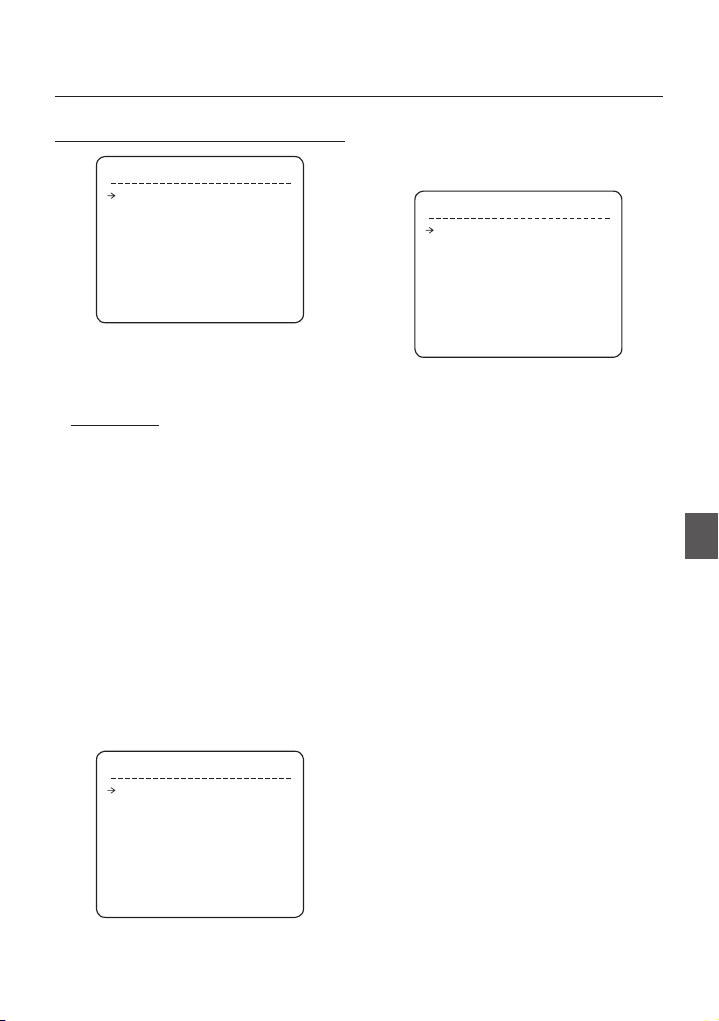
Utilisation du menu OSD
CONFIG CAMÉRA
CONFIG ZOOM CAMÉRA
M. MISE AU PT SEMIAUTO
ZOOM NUMÉRIQUE
FLIP IMAGE OFF
<CONFIG BALANCE BLANCS>
<CONFIG. EXPOS AUTO>
RETOUR
QUIT.
Confi gurez les fonctions générales de la caméra du module zoom.
M. MISE AU PT [AUTO/MANUEL/SEMIAUTO]
•
Mode SEMIAUTO
–
Ce mode permet de basculer automatiquement le mode
de mise au point entre les modes Mise au point manuelle
et Mise au point automatique. Le mode Mise au point
manuelle s’active pendant le fonctionnement préréglé et
le mode Mise au point automatique s’active pendant le
fonctionnement image par image.
Lors du préréglage du mode manuel, les données de mise
au point sont préalablement enregistrées pour chaque
préréglage et la caméra appelle les données correspondant
aux préréglages dès qu’elle atteint un préréglage.
ZOOM NUMÉRIQUE [ON/OFF]
•
Permet de régler la fonction de zoom numérique
sur ON/OFF. Si elle est réglée sur OFF, la fonction
de zoom optique se lance mais s’arrête à la fi n de
l’agrandissement à l’aide du zoom optique.
FLIP IMAGE [ON/OFF]
•
Pour affi cher l’image à l’envers.
Confi g balance blancs
❖
CONFIG BAL BL
MODE BAL BLANCS
RÉGLAGE ROUGE
-
- RÉGLAGE BLEU ---
RETOUR
QUIT.
MODE BAL BLANCS [AUTO/MANUEL]
•
En mode Manuel, le niveau du rouge et du bleu peut
être réglé manuellement.
ON
Permet de régler le mode de mise au
point de la caméra.
AUTO
---
•
•
Confi g. expos auto
❖
•
•
•
•
•
•
•
RÉGLAGE ROUGE [10~60]
RÉGLAGE BLEU [10~60]
CONF EXP AUTO
RÉTROÉCL OFF
JOUR/NUIT AUTO1
LUMINOSITÉ 25
IRIS AUTO
OBTURAT. ECH
AGC NORMAL
DNR MOYEN
SENS + OFF
RETOUR
QUIT.
RÉTROÉCL [OFF/BAS/MOYEN/ÉLEV]
Règle la compensation du rétroéclairage
JOUR/NUIT [AUTO1/AUTO2/JOUR/NUIT]
AUTO1 change le mode Jour/Nuit plus rapidement
qu’AUTO2.
LUMINOSITÉ [0~100]
Permet de régler la luminosité des images. Le
diaphragme, la vitesse de l’obturateur et le gain sont
réglés automatiquement en fonction de cette valeur.
IRIS (DIAPHRA) [AUTO/MANUEL(0~100)]
Si l’option Diaphra est réglée sur Auto, le diaphragme
sera prioritaire par rapport aux réglages Exp auto et
Vit obturat.
Lorsque l’option Diaphra est spécifi ée sur Manuel,
il faut régler le diaphragme. Celui-ci a dès lors
une moindre priorité pour le réglage Exp auto que
d’autres options.
VITESSE DE L’OBTURATEUR
[ECH/PRT PAPIL/MANUEL(×128~1/120000 s)]
Si l’option Diaphra est réglée sur Manuel et Vit obturat.
sur ECH, la fonction Vit obturat. deviendra prioritaire.
Lorsque l’option Vit obturat. est réglée sur Prt papil,
qui permet d’éliminer le papillotement, la fonction Vit
obturat. doit être spécifi ée sur 1/100 s en mode NTSC
et sur 1/120 en mode PAL.
AGC [OFF/NORMAL/ÉLEV]
Permet d’augmenter automatiquement la luminosité
de l’image lorsque le niveau de luminance du signal
de l’image est trop faible.
DNR [OFF/BAS/MOYEN/ÉLEV]
Améliore les images en réduisant les bruits lorsque le
niveau de gain des images est trop élevé.
Français – 33
FRE

Utilisation du menu OSD
SENS + [AUTO(2~128)/OFF]
•
Active la vitesse lente de l’obturateur lorsque la
luminance de l’image (signal) est trop obscure.
Il est possible de confi gurer le nombre maximum
d’images empilées l’une sur l’autre via la fonction Vit
obturat. lente.
CONFIGURATION SYSTÈME
CONFIG DATE/HEURE
•
Après avoir appuyé sur PRÈS ou sur la touche
ENTRÉE, vous pouvez sélectionner les champs à l’aide
des touches directionnelles gauche/droite et en modifi er
les valeurs via les touches directionnelles haut/bas.
Pour sauvegarder les données mises à jour, appuyez à
nouveau sur PRÈS ou sur la touche ENTRÉE.
Notez que la plage de réglage de la date s’étend du
01/JAN/2000 au 31/DEC/2037.
CONFIGURATION SYSTÈME
<CONFIG DATE/HEURE>
<TYPE RELAIS>
<MOT DE PASSE>
<RÉG POSITION ACCUEIL>
<RÉG POSITION NORD>
LANGUE ENGLISH
<CONF VEN/RÉCHAUF>
RETOUR
QUIT.
•
CONFIGURATION SYSTÈME
Vous pouvez confi gurer les fonctions suivantes :
DATE/HEURE, TYPE RELAIS, MOT DE PASSE, POS
ACCUEIL, POSITION NORD.
Le menu <CONF VEN/RÉCHAUF> n’est disponible que
sur le modèle C7325.
CONFIG DATE/HEURE
DATE 01/JAN/2008(MAR)
HEURE 00:00:01(H/M/S)
RETOUR
QUIT.
•
DATE
La date s’affi che au format jj/mmm/aaaa. Le jour est
automatiquement calculé lorsque vous défi nissez une
date.
•
HEURE
L’heure s’affi che au format HH:MM:SS.
CONFIG TYPE RELAIS
REL.1 OUVERTURE NORM.
RETOUR
QUIT.
CONFIG TYPE RELAIS
•
Un contact de type 1 SORTIES DE RELAIS est défi ni.
(OUVERTURE NORM. / FERMETURE NORM.)
OUVERTURE NORM.
FERMETURE NORM.
EDIT PASSWORD
[█ ]
--------- 1234567890 OK
ABCDEFGHIJ ANNULER
KLMNOPQRST
UVWXYZabcd DISABLE
efghijklmn
opqrstuvwx
yz<>-/:.
CONFIGURATION DU MOT DE PASSE
•
Vous pouvez défi nir un mot de passe de 4 caractères.
Si cette fonction est réglée sur ACTIVER, vous devrez
toujours saisir ce mot de passe pour accéder au menu
OSD.
MOT DE PASSE MAÎTRE : « 4321 »
34 – 10X MINI SMART DOME CAMERA

Utilisation du menu OSD
CONF VEN/RÉCHAUF
TEMP EXÉ VEN 40°C
TEMP EXÉ RÉCHAU 5°C
RETOUR
QUIT.
TEMP EXÉ VEN
•
Au-dessus de cette température, le ventilateur souffl ant
démarre automatiquement.
Plage : 30°C ~ 80°C (86°F ~ 176°F)
TEMP EXÉ RÉCHAU
•
Au-dessous de cette température, le réchauffeur est
activé automatiquement.
Plage : -10°C ~ 20°C (14°F ~ 68°F)
Les options VEN et RÉCHAU ne sont disponibles que
sur le modèle C7325.
RÉG POSITION ACCUEIL
DÉPLACER VERS POS. CIBLE
[PRÈS:SÉLECT/LOIN:ANNUL]
•
RÉG POSITION ACCUEIL
La position ACCUEIL correspond à l’origine du calcul
de l’angle PANORAMIQUE. La valeur PANORAMIQUE
affi chée à l’écran est basée sur la position ACCUEIL.
En utilisant le joystick, déplacez la caméra sur la position
souhaitée et appuyez sur ENTRÉE (PRÈS/SAUVEG).
Notez que la position Accueil n’est pas activée avec
l’angle Horizontal/Vertical.
Si vous changez l’emplacement de Pos Accueil, les
emplacements horizontaux des fonctions telles que
Prérég, Modèle, Balay., Pan auto et Masq. zone
confi dent. seront changés conformément au nouvel
emplacement de Pos Accueil.
0/0/x1/N
* Rég Position Accueil ?
En cas de remplacement du bloc caméra ou de
changement d’orientation de la caméra en raison
d’opérations de maintenance, il est très diffi cile de
conserver la même orientation de panoramique.
Pour cette raison, les données liées aux fonctions
qui dépendent de l’orientation du panoramique,
telles que Prérég, Modèle, Balay., Pan auto et Masq.
zone confi dent. ne sont plus utiles en conséquence.
Cependant, même dans ce cas, vous pourrez
réutiliser les données si vous redéfi nissez Rég
Position Accueil sur la position précédente de Pos
Accueil. Il est recommandé de mémoriser la scène
cible de la position actuelle de Pos Accueil.
RÉG POSITION NORD
DÉPLACER VERS POS. CIBLE
[PRÈS:SÉLECT/LOIN:ANNUL]
RÉG POSITION NORD
•
Vous pouvez confi gurer la position nord.
En utilisant le joystick, déplacez la caméra sur la position
NORD souhaitée et appuyez sur ENTRÉE (PRÈS/
SAUVEG).
La direction s’affi che à l’écran.
[AXE PANORAMIQUE / AXE VERTICAL-
HORIZONTAL / ZOOM / DD]
DD correspond à la direction et s’affi che sous la forme
suivante :
N/NE/E/SE/S/SO/O/NO
LANGUE
•
Vous pouvez sélectionner une langue préférée
d’affi chage à l’écran parmi un choix de 7 langues.
[ENGLISH/ ESPAÑOL/ FRANÇAIS/ DEUTSCH/
ITALIANO/ РУССКИЙ/ PORTUGUÊS]
Après avoir sélectionné une langue, appuyez sur la
touche ENTRÉE (PRÈS).
0/0/x1/N
FRE
Français – 35

Utilisation du menu OSD
Tableau de confi guration initiale
INITIALISER SYSTÈME
INITIALISER SYSTÈME
EFF TTES DONNÉES NO
EFF RÉG ÉCRAN NO
EFF RÉG CAMÉRA NO
EFF MOUVEMENT NO
EFF RÉG FONCTION NO
REDÉMARRER CAMÉRA NO
REDÉMARRER SYSTÈME NO
RETOUR
QUIT.
EFF TTES DONNÉES
•
Permet de supprimer toutes les données de
confi guration telles que l’écran,
la caméra, la confi guration des mouvements, etc.
EFF RÉG ÉCRAN
•
Permet d’initialiser la confi guration de l’écran
EFF RÉG CAMÉRA
•
Permet d’initialiser la confi guration de la caméra
EFF RÉG MOUVEMENT
•
Permet d’initialiser la confi guration des mouvements
EFF RÉG FONCTION
•
Permet de supprimer les données préréglées, les
données panoramiques automatiques, les données de
modèle, les données de balayage et les données de
programmation
REDÉMARRER CAMÉRA
•
Permet de redémarrer la caméra du module zoom
REDÉMARRER SYSTÈME
•
Redémarre la caméra Smart Dome
❖
Confi guration de l’affi chage
•
ID caméra ON
Info PTZ AUTO
Titre action AUTO
Étiquette prérég. AUTO
E/S alarme AUTO
Date/Heure ON
Température CELSIUS
Rég position nord Pan 0°
Zone confi dent. Non déf.
Confi guration des mouvements
•
Verrouil. prér. OFF
Mise sous tension ON
Flip auto ON
Vit max im.p.im 140°/s
Direct. im.p.im NORMAL
Gel en préréglage OFF
Action parc OFF
Action E/S alarme OFF
Confi guration de la communication
•
Protocole AUTO
Débit en bauds 9600
36 – 10X MINI SMART DOME CAMERA

Utilisation du menu OSD
Confi guration caméra
•
M. Mise au pt SEMIAUTO
Zoom numérique ON
Flip image OFF
Balance des blancs AUTO
Rétroécl OFF
Jour/Nuit AUTO1
Luminosité 25
Diaphra AUTO
Obturat. ECH
AGC NORMAL
DNR MOYEN
Augmentation de la sensibilité OFF
Données de fonction
•
Préréglage 1 à 128 Non déf.
Panoramique automatique 1 à 8 Non déf.
Modèle 1 à 4 Non déf.
Balayage 1 à 8 Non déf.
Programmation 1 à 7 Non déf.
FRE
Français – 37

Caractéristiques techniques
CARACTÉRISTIQUES TECHNIQUES
Modèle SCC-C6323N/P
Système de signaux vidéo
CCD
Nbre de pixels maxi
Nombre de pixels réels
Résolution horizontale
Rapport signal/bruit
Longueur focale
Luminosité minimale
Caméra
Jour/Nuit
Focus
Diaphragme
Vitesse de l’obturateur
AGC (Controle
Automatique du Gain)
Balance des blancs
BLC
DNR
Plage
Vitesse panoramique/
Panoramique/
Horizontal-
Généralités
horizontale-verticale
Vertical
Préréglage
Modèle
Panoramique
automatique
Balay.
Autres fonctions
Communication
Protocole
Zone confi dent.
Entrée d’alarme
Sortie d’alarme
OSD
Puissance nominale**
Consommation
Dimensions
Poids
Température de fonctionnement
Zoom
Capteur CCD 1/4” à transfert d’interligne
811(H)×508(V) 410K 795(H)×596(V) 470K
768(H)×494(V) 380K 752(H)×582(V) 440K
520 ligne TV(Couleur), 570 ligne TV(NB)
Zoom optique 10x , zoom numérique 10x
Luminosité
50 IRE N° 0.60 Lux 0.06 Lux
30 IRE N° 0.36 Lux 0.036 Lux
15 IRE N° 0.18 Lux 0.018 Lux
50 IRE 128 Fois 0.0047 Lux 0.00047 Lux
30 IRE 128 Fois 0.0028 Lux 0.00028 Lux
15 IRE 128 Fois 0.0014 Lux 0.00014 Lux
x128 ~ 1/120000 s, Protection contre papillotements
Manuel : 0,05 à 360°/s (proportionnelle au zoom)
Panoramique automatique : 1 à 180°/s
127 préréglages (réglage de l’étiquette, de l’image de caméra)
4 modèles, 1200 commandes (environ 5 minutes/modèle)
8 balayages (20 entités d’action par balayage)
Flip auto, parking auto, mise sous tension, etc.
Auto, Pelco-D, Pelco-P, sélectionnable par Samsung
Prise en charge de 7 langues : [ENGLISH /ESPAÑOL /
FRANÇAIS /DEUTSCH/ITALIANO /РУССКИЙ /PORTUGUÊS]
Dôme ø100.5
Boîtier ø142 × 126(H) mm
38 – 10X MINI SMART DOME CAMERA
NTSC PAL
50 dB (AGC Off)
F1.8, f=3.8~38mm
Augmentation
de la sensibilité
Auto / Manuel / SemiAuto
Auto / Manuel (gain rouge, bleu réglable)
Bas / Moyen / Élev / Off
Bas / Moyen / Élev / Off
Panoramique : 0-360°(sans fi n)
Horizontal-Vertical : 0~90°
8 panoramiques automatiques
Tension double CA 24 V / CC 12 V
AC24V (10W) / DC12V (8 W)
Couleur NB (C/B)
Auto / Jour / Nuit (ICR)
Auto / Manuel
Normal / Élev / Off
Prérég. : 360°/s
RS-485
4 zones
2 entrées
1 sorties de relais
Menu / Info PTZ, etc.
environ 0.6 Kg
-10°C à 50°C
Apparence
❖
Unité principale
•
Les caractéristiques de cet appareil sont
susceptibles d’être modifi ées sans préavis.
Vérifi ez attentivement la tension nominale et la
capacité de l’alimentation électrique.

Caractéristiques techniques
Modèle SCC-C6325N/P
Système de signaux vidéo
CCD
Nbre de pixels maxi
Nombre de pixels réels
Résolution horizontale
Rapport signal/bruit
Longueur focale
Luminosité minimale
Caméra
Jour/Nuit
Focus
Diaphragme
Vitesse de l’obturateur
AGC (Controle
Automatique du Gain)
Balance des blancs
BLC
DNR
Plage
Vitesse panoramique/
Vertical
horizontale-verticale
Préréglage
Modèle
Panoramique
automatique
Balay.
Autres fonctions
Communication
Protocole
Zone confi dent.
Entrée d’alarme
Sortie d’alarme
OSD
Puissance nominale**
Consommation
Dimensions
Poids
Température de
fonctionnement
Panoramique/
Horizontal-
Généralités
Zoom
NTSC PAL
Capteur CCD 1/4” à transfert d’interligne
811(H)×508(V) 410K 795(H)×596(V) 470K
768(H)×494(V) 380K 752(H)×582(V) 440K
520 ligne TV(Couleur), 570 ligne TV(NB)
Zoom optique 10x , zoom numérique 10x
Luminosité
50 IRE N° 0.60 Lux 0.06 Lux
30 IRE N° 0.36 Lux 0.036 Lux
15 IRE N° 0.18 Lux 0.018 Lux
50 IRE 128 Fois 0.0047 Lux 0.00047 Lux
30 IRE 128 Fois 0.0028 Lux 0.00028 Lux
15 IRE 128 Fois 0.0014 Lux 0.00014 Lux
x128 ~ 1/120000 s, Protection contre papillotements
Auto / Manuel (gain rouge, bleu réglable)
Inclinaison : 0~180° (Mode Flip auto), 90°(Normal)
Manuel : 0,05 à 360°/s (proportionnelle au zoom)
Panoramique automatique : 1 à 180°/s
127 préréglages (réglage de l’étiquette, de l’image de caméra)
4 modèles, 1 200 commandes par modèle
(près de 5 minutes en mode de fonctionnement normal)
8 balayages (20 entités d’action par balayage)
Flip auto, parking auto, mise sous tension, etc.
Auto, Pelco-D, Pelco-P, sélectionnable par Samsung
Prise en charge de 7 langues : [ENGLISH /ESPAÑOL /
FRANÇAIS /DEUTSCH/ITALIANO /РУССКИЙ /PORTUGUÊS]
Tension double CA 24 V / CC 12 V
Dôme ø115
Boîtier ø165 × 162(H) mm
50 dB (AGC Off)
F1.8, f=3.8~38mm
Augmentation
de la sensibilité
Auto / Manuel / SemiAuto
Bas / Moyen / Élev / Off
Bas / Moyen / Élev / Off
Panoramique : 0-360°(sans fi n)
8 panoramiques automatiques
AC24V (10W) / DC12V (8W)
Couleur NB (C/B)
Auto / Jour / Nuit (ICR)
Auto / Manuel
Normal / Élev / Off
Prérég. : 360°/s
RS-485
4 zones
2 entrées
1 sorties de relais
Menu / Info PTZ, etc.
environ 1.85 Kg
-10°C à 50°C
Apparence
❖
Unité principale
•
Les caractéristiques de cet appareil sont
susceptibles d’être modifi ées sans préavis.
Vérifi ez attentivement la tension nominale et l
a capacité de l’alimentation électrique.
Français – 39
FRE
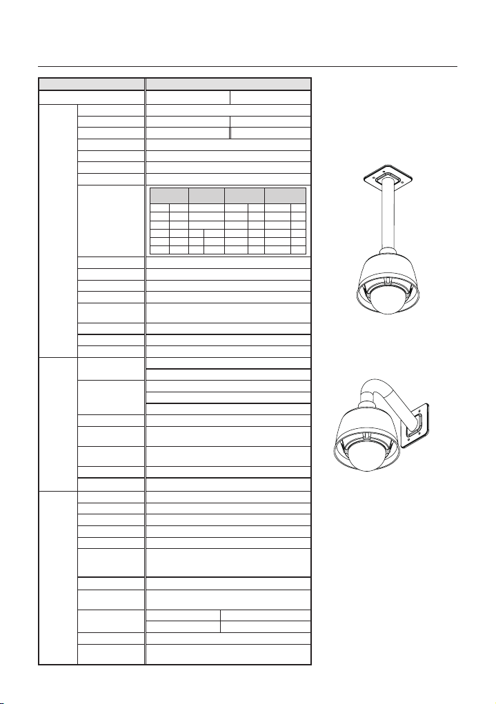
Caractéristiques techniques
Modèle SCC-C7325N/P
Système de signaux vidéo
CCD
Nbre de pixels maxi
Nombre de pixels réels
Résolution horizontale
Rapport signal/bruit
Zoom
Longueur focale
Luminosité minimale
Caméra
Jour/Nuit
Focus
Diaphragme
Vitesse de l’obturateur
AGC (Controle
Automatique du Gain)
Balance des blancs
BLC
DNR
Plage
Vitesse panoramique/
Vertical
horizontale-verticale
Préréglage
Modèle
Panoramique
automatique
Balay.
Autres fonctions
Communication
Protocole
Zone confi dent.
Entrée d’alarme
Sortie d’alarme
OSD
Puissance nominale**
Consommation
Dimensions
Poids
Température de
fonctionnement
Panoramique/
Horizontal-
Généralités
40 – 10X MINI SMART DOME CAMERA
NTSC PAL
Capteur CCD 1/4” à transfert d’interligne
811(H)×508(V) 410K 795(H)×596(V) 470K
768(H)×494(V) 380K 752(H)×582(V) 440K
520 ligne TV(Couleur), 570 ligne TV(NB)
50 dB (AGC Off)
Zoom optique 10x , zoom numérique 10x
F1.8, f=3.8~38mm
Augmentation
Luminosité
de la sensibilité
50 IRE N° 0.60 Lux 0.06 Lux
30 IRE N° 0.36 Lux 0.036 Lux
15 IRE N° 0.18 Lux 0.018 Lux
50 IRE 182 Fois 0.0047 Lux 0.00047 Lux
30 IRE 182 Fois 0.0028 Lux 0.00028 Lux
15 IRE 182 Fois 0.0014 Lux 0.00014 Lux
Auto / Manuel / SemiAuto
x128 ~ 1/120000 s, Protection contre papillotements
Auto / Manuel (gain rouge, bleu réglable)
Bas / Moyen / Élev / Off
Bas / Moyen / Élev / Off
Panoramique : 0-360°(sans fi n)
Inclinaison : 0~180° (Mode Flip auto), 90°(Normal)
Manuel : 0,05 à 360°/s (proportionnelle au zoom)
Panoramique automatique : 1 à 180°/s
127 préréglages (réglage de l’étiquette, de l’image de caméra)
4 modèles, 1 200 commandes par modèle
(près de 5 minutes en mode de fonctionnement normal)
8 panoramiques automatiques
8 balayages (20 entités d’action par balayage)
Flip auto, parking auto, mise sous tension, etc.
Auto, Pelco-D, Pelco-P, sélectionnable par Samsung
Prise en charge de 7 langues : [ENGLISH /ESPAÑOL /
FRANÇAIS /DEUTSCH/ITALIANO /РУССКИЙ /PORTUGUÊS]
Tension double CA 24 V / CC 12 V
AC24V : Réchauffeur désactivé (10 W) / activé (21 W)
DC12V : Réchauffeur désactivé (8 W) / activé (12 W)
Dôme ø115
Boîtier ø200 × 206(H) mm
-40°C à 50°C (Type de ventilateur et de réchauffeur intégrés)
Couleur NB (C/B)
Auto / Jour / Nuit (ICR)
Auto / Manuel
Normal / Élev / Off
Prérég. : 360°/s
RS-485
4 zones
2 entrées
1 sorties de relais
Menu / Info PTZ, etc.
environ 2.4 Kg
Apparence
❖
Fixation plafond
•
Fixation murale
•
Les caractéristiques de cet appareil sont
susceptibles d’être modifi ées sans préavis.
Vérifi ez attentivement la tension nominale et l
a capacité de l’alimentation électrique.

Caractéristiques techniques
DIMENSIONS
SCC-C6323❖ SCC-C6325❖
Unité (mm)
FRE
TUBE FILETÉ
Français – 41

Caractéristiques techniques
SCC-C7325❖
Support de fi xation murale
•
Support pour fi xation plafond
•
Unité (mm)
42 – 10X MINI SMART DOME CAMERA

Les bons gestes de mise au rebut de ce produit
(Déchets d’équipements électriques et électroniques)
(Applicable dans les pays de l’Union Européenne et dans d’autres pays européens pratiquant le tri sélectif)
Ce symbole sur le produit, ses accessoires ou sa documentation indique que ni le produit, ni ses accessoires
électroniques usagés (chargeur, casque audio, câble USB, etc.) ne peuvent être jetés avec les autres déchets
ménagers. La mise au rebut incontrôlée des déchets présentant des risques environnementaux et de santé
publique, veuillez séparer vos produits et accessoires usagés des autres déchets. Vous favoriserez ainsi le
recyclage de la matière qui les compose dans le cadre d’un développement durable.
Les particuliers sont invités à contacter le magasin leur ayant vendu le produit ou à se renseigner auprès
des autorités locales pour connaître les procédures et les points de collecte de ces produits en vue de leur
recyclage.
Les entreprises et professionnels sont invités à contacter leurs fournisseurs et à consulter les conditions
de leur contrat de vente. Ce produit et ses accessoires ne peuvent être jetés avec les autres déchets
professionnels et commerciaux.
AB82-02247A

SCC-C6323P
SCC-C6325P
SCC-C7325P
Smart Dome Kamera mit
10facher Geschwindigkeit
Benutzerhandbuch
GER
Erleben Sie die Möglichkeiten
Danke, dass Sie sich für dieses Produkt von Samsung entschieden haben.
Um den vollständigen Service zu erhalten,
registrieren Sie Ihr Produkt unter
www.samsungsecurity.com

Sicherheitsinformationen
VORSICHT
GEFAHR EINES
ELEKTROSCHOCKSNICHT ÖFFNEN
VORSICHT: NICHT DIE RÜCKSEITIGE ABDECKUNG ÖFFNEN, ABDECKUNG (ODER RÜCKSEITE) NICHT ABNEHMEN. KEINE
VOM BENUTZER ZU WARTENDE TEILE INNEN. WENDEN SIE SICH AN QUALIFIZIERTESKUNDENDIENSTPERSONAL
Dieses Symbol zeigt an, dass bei diesem Gerät gefährliche Spannung Elektroschock zur
Folge haben kann.
Dieses Symbol zeigt an, dass wichtige Betriebs- und Wartungsanleitungen in dem Prospekt
enthalten sind, der mit diesem Gerät geliefert wird.
WARNUNG
Setzen Sie dieses Gerät nicht Regen oder Feuchtigkeit aus, um die Gefahr eines Brands oder Elektroschocks
•
zu reduzieren.
WARNUNG
Achten Sie darauf, nur den im Datenblatt angegebenen Standard- Adapter zu verwenden. Die Verwendung
1.
eines anderen Adapters kann Brand, Elektroschock oderSchäden am Produkt verursachen.
Falscher Anschluss des Netzkabels oder Austausch der Batterie kann Explosion, Brand, Elektroschock oder
2.
Schäden am Produkt zur Folge haben.
Schließen Sie nicht mehrere Kameras an einen einzelnen Adapter an. Überschreiten der Kapazität kann
3.
abnormale Wärme oder Brand erzeugen.
Schließen Sie das Netzkabel sicher an die Steckdose an. Ein ungesicherter Anschluss kann einen Brand
4.
verursachen.
Wenn Sie die Kamera installieren, befestigen Sie sie sicher und fest.Eine herunterfallende Kamera kann
5.
Körperverletzungen verursachen.
Stellen Sie keine leitenden Gegenstände (z.B. Schraubendreher, Münzen, Metallgegenstände, usw.)
6.
oder Behälter mit Wasser auf die Kamera. Dies kann sonst Körperverletzungen aufgrund von Brand,
Elektroschock oder herunterfallenden Gegenständen verursachen.
Installieren Sie das Gerät nicht an feuchten, staubigen oder rußigen Standorten. Dies führt sonst zu Brand
7.
oder Elektroschock.
Verwenden Sie das Produkt nicht weiter, wenn eine ungewöhnliche Geruchs- oder Rauchentwicklung
8.
auftritt. Ziehen Sie in diesem Fall sofort den Netzstecker und wenden Sie sich an den Kundendienst.
Wenn Sie das Gerät unter diesen Bedingungen weiterhin verwenden, kann Brand oder Elektroschock
resultieren.
9.
Wenn dieses Produkt nicht einwandfrei funktioniert, wenden Sie sich an den nächstgelegenen
Kundendienst. Zerlegen oder modifi zieren Sie dieses Produkt nie in irgendeiner Weise. (SAMSUNG haftet
nicht für Schäden, die durch unbefugte Änderungen oder Reparaturversuche verursacht werden.)
2 – 10X MINI SMART DOME CAMERA

Sicherheitsinformationen
Spritzen Sie während der Reinigung kein Wasser direkt auf die Produktteile. Dies führt sonst zu Brand oder
10.
Elektroschock.
Wenn die Kamera bei einer Umgebungstemperatur unter dem Gefrierpunkt (0 °C) nach einem Stromausfall
11.
installiert oder neu gestartet wird, ist die Kuppelabdeckung vereist. Das Eis wird 3 Stunden nach
Inbetriebnahme wieder abgetaut sein.
(Beachten Sie, dass die garantierte Mindestbetriebstemperatur bei -45° C liegt (-49° F) ohne Wind).
VORSICHT
Lassen Sie keine Gegenstände auf das Produkt fallen oder setzen Sie es keinen starken Stößen aus. Halten
1.
Sie sich fern von Standorten die übermäßiger Erschütterung oder magnetischer Beeinfl ussung ausgesetzt
sind.
Installieren Sie das Gerät nicht an einem Standort, der hohen Temperaturen (über 50°C), niedrigen
2.
Temperaturen (unter -10°C) oder hoher Feuchtigkeit ausgesetzt ist. Dies führt sonst zu Brand oder
Elektroschock.
Wenn Sie das bereits installierte Gerät versetzen möchten, achten Sie darauf, die Stromversorgung
3.
abzuschalten und es dann erst zu versetzen und erneut zu installieren.
Ziehen Sie den Netzstecker bei Gewitter. Nichtbeachtung kann Brand oder Schäden am Gerät verursachen.
4.
Halten Sie das Gerät fern von direktem Sonnenlicht und anderen Wärmestrahlungsquellen. Dies kann sonst
5.
zu Brand führen.
Installieren Sie das Gerät an einem Ort mit guter Belüftung.
6.
Zielen Sie mit der Kamera nicht direkt in Richtung extrem heller Gegenstände wie zum Beispiel die Sonne,
7.
da dies den CCDBildsensor beschädigen kann.
Das Gerät darf nicht mit Wasser oder anderen Flüssigkeiten in Berührung kommen.
8.
Außerdem dürfen keine mit Flüssigkeiten gefüllten Behälter, wie beispielsweise Vasen, darauf abgestellt
werden.
9.
Der Netzstecker sollte jederzeit in Reichweite und zugänglich sein, da er aus der Steckdose entfernt werden
muss, um das Gerät vollständig abzuschalten.
GER
Deutsch – 3

Wichtige Sicherheitshinweise
Lesen Sie diese Anweisungen.
1.
Bewahren Sie sie auf.
2.
Beachten Sie alle Warnungen.
3.
Befolgen Sie alle Anweisungen.
4.
Verwenden Sie dieses Gerät nicht in der Nähe von Wasser.
5.
Reinigen Sie es nur mit einem trockenen Lappen.
6.
Blockieren Sie keine Belüftungsöffnungen. Installieren Sie es gemäß den Herstelleranweisungen.
7.
Installieren Sie das Gerät nicht in der Nähe von Wärmequellen wie beispielsweise von Radiatoren, Heizkörpern
8.
oder anderen Geräten (einschließlich Verstärkern), die Wärme erzeugen.
Bitte achten Sie darauf, die Schutzvorrichtung des gepolten bzw.
9.
geerdeten Steckers nicht zu beschädigen. Ein gepolter Stecker verfügt über zwei Stifte, von denen einer breiter
als der andere ist. Ein geerdeter Stecker hat zwei Stifte und einen Erdungsstift. Der breite Stift oder der dritte Stift
ist für Ihre Sicherheit vorgesehen. Wenn der vorgesehene Stecker nicht in Ihre Steckdose passt, wenden Sie sich
an einen Elektriker, um die veraltete Steckdose austauschen zu lassen.
Schützen Sie das Netzkabel so, dass nicht darauf getreten wird, und dass es insbesondere an den Steckern
10.
oder passenden Steckdosen bzw. der Stelle, an der das Kabel das Gerät verlässt, nicht
abgeklemmt wird.
Verwenden Sie nur die vom Hersteller angegebenen Zusatzgeräte/Zubehörteile.
11.
Verwenden Sie diese nur mit dem vom Hersteller angegebenen Wagen, Ständer, Stativ,
12.
Aufl age oder Tisch, oder die mit dem Gerät zusammen verkauft wurden.
Ziehen Sie den Netzstecker dieses Geräts. Geben Sie Acht bei der Verwendung eines
13.
Wagens, wenn Sie die Wagen-/Gerätekombination verschieben, um Verletzungen durch
Herunterfallen zu vermeiden.
Überlassen Sie alle Wartungsarbeiten qualifi ziertem Kundendienstpersonal.
14.
Wartungsarbeiten sind erforderlich, wenn das Gerät in irgendeiner Weise beschädigt wurde, wie zum Beispiel ein
beschädigtes Netzkabel oder Stecker, verschüttete Flüssigkeiten oder Gegenstände, die in das Gerät gefallen
sind, das Gerät Regen oder Feuchtigkeit ausgesetzt wurde, nicht normal funktioniert oder fallen gelassen wurde.
4 – 10X MINI SMART DOME CAMERA

Inhalt
Einführung
Leistungsmerkmale 7
Produkt und zubehör 8
Bezeichnung und funktionen der komponenten 10
Montage
DIP-Schalter einstellen 13
Montage mit deckenhalterung 14
Montage mit Wandhalterung (SCC-C7325) 16
Montage mit Wandhalterung (SCC-C7325) 17
Verkabelung 19
Betrieb
Prüfpunkte vor inbetriebnahme 21
Voreinstellungs- und musterfunktion vorprüfen 21
Autokalibrierung 21
Bildschirmanzeigemenü starten 21
Reservierte voreinstellungen 21
Voreinstellung 22
Auto-Pan 22
Muster 22
Scan 23
Zeitplan 23
Weitere funktionen 23
Bildschirmanzeige des hauptbildschirms 24
Allgemeine regeln der tastenverwendung in den menüs 25
Hauptmenü 25
Systeminformationen 25
Bildschirmeinstellungen 25
GER
Deutsch – 5

Inhalt
Bildschirmanzeigemenü verwenden
Masken für privatbereiche einstellen 26
Bewegungseinstellungen 26
Einstellungen für funktionen 27
Voreinstellungen einrichten 28
Einstellungen für auto-pan 29
Einstellungen für muster 30
Einstellungen Scan 30
Einstellungen für zeitpläne 32
Kameraeinstellungen 33
Systemeinstellungen 34
System initialisieren 36
Technische Daten
Technische Daten 38
Abmessungen 41
6 – 10X MINI SMART DOME CAMERA

Einführung
LEISTUNGSMERKMALE
Technische Daten der Kamera
❖
CCD-Sensor : 1/4” Interline Transfer CCD
•
Vergrößerung : 10 × optischer Zoom, 10 × digitaler
•
Zoom (max. Zoom : 100 ×)
Tag/Nacht-Funktion
•
Verschiedene Fokusmodi: Autofokus / manueller
•
Fokus / halbautomatischer Fokus
Freie oder allgemeine Kameraeinstellungen bei
•
voreingestelltem Betrieb
Leistungsstarke Schwenk-/Neigefunktionen
❖
Schwenk-/Neigebewegung in Hochgeschwindigkeit
•
mit max. 360°/s
Mit der „Vector Drive“-Technologie werden
•
Schwenk-/Neigebewegungen auf dem kürzesten
Weg ausgeführt. Dadurch wird die Ausrichtung auf
die Zielansicht enorm beschleunigt, und das Video
auf dem Monitor wirkt besonders natürlich.
Zum Jog-Betrieb mithilfe eines Controllers; da eine
•
äußert geringe Geschwindigkeit von 0,05°/Sek.
erreicht werden kann, ist es sehr einfach, die Kamera
zum gewünschten Ziel hin auszurichten.
Aufgrund der Schwenk-/Neigegeschwindigkeit,
•
die gleich der Zoomgeschwindigkeit ist, kann
die Kamera trotz hoher Zoomrate genau zur
gewünschten Position bewegt werden.
Voreinstellung, Muster, Auto-Pan, Scan,
❖
Privatbereichsmaske, Zeitplan und
weitere Funktionen
MAX. 127 Voreinstellungen können zugewiesen
•
werden; die Merkmale der einzelnen Voreinstellungen,
z. B. Weissabgleich, automatische Belichtungszeit,
Name, etc., können frei festgelegt werden.
Für das automatische Schwenken (Auto-Pan)
•
können bis zu 8 Einstellungen gespeichert werden.
Dadurch kann die Kamera bei gewünschter
Geschwindigkeit wiederholt von einer voreingestellten
Positionen zur anderen bewegt werden.
Max. 4 Muster können gespeichert und ausgeführt
•
werden. Dadurch kann die Kamera eine engstmögliche
Überwachungsbahn ziehen, die durch die Bewegung
des Joysticks durch den Bediener aufgezeichnet wird.
Max. 8 Scans können gespeichert werden. Zur Erstellung
•
einer Überwachungsbahn kann die Gruppe über max.
Funktionseinheiten Vrst/Muster/Scan verfügen.
Dadurch kann sich die Kamera wiederholt aufgrund einer
Kombination aus diesen Funktionen bewegen.
Max. 4 Masken können zur Wahrung des
•
Privatbereichs beliebig festgelegt werden. Die Maske
ist ein Rechteck mit einer frei wählbaren Größe und
kann für jeden Bereich des Überwachungsraumes
eingerichtet werden.
Es können 7 Zeitplanregeln nach Tag und Uhrzeit festgelegt
•
werden. Für jede Regel lassen sich geeignete Aktionen
(z. B. Ausgangsposition, Voreinstellung, Scan, Muster
oder Auto-Pan) defi nieren. Zur Vereinfachung ist es auch
möglich, als Regel Wochentag und Täglich festzulegen.
Steuerung der PTZ- (Schwenk-/ Neige-/
❖
Zoom-) Funktion
Mit der RS-485-Kommunikation ist die gleichzeitige
•
Steuerung von bis zu 255 Kameras möglich.
In der aktuellen Firmware-Version stehen die
•
Protokolle Pelco-D, Pelco-P und Samsung als
Steuerprotokolle zur Auswahl.
Menü der Bildschirmanzeige
❖
Das Bildschirmanzeigemenü dient der Anzeige des
•
Kamerastatus und der interaktiven Konfi guration von
Funktionen.
Zurzeit werden vom Bildschirmmenü 7 Sprachen
•
unterstützt : [ENGLISH/ESPAÑOL/FRANÇAIS/
DEUTSCH/ITALIANO/РУССКИЙ/PORTUGUÊS]
Am Bildschirm werden Informationen wie Kamera-
•
ID, Pan/Tilt/Zoom/Richtung, Alarmeingang und
-ausgang, Datum/Zeit, aktuelle Temperatur und
Voreinstellungen angezeigt.
Jedes Anzeigeelement kann einzeln ein- oder
•
ausgeblendet werden.
Alarm-E/A-Funktionen
❖
2 Eingänge für Alarmsensoren und 1 Relais-Ausgang
•
sind verfügbar.
Um externes elektrisches Rauschen und elektrischen
•
Schlag zu verhindern, ist der Alarmsensoreingang
vom Fotokoppler entkoppelt.
Die Kamera kann so eingestellt werden, dass
•
sie bei Aktivierung eines externen Sensors in die
entsprechende Voreinstellungsposition bewegt wird.
Relais-Ausgänge können bestimmten
•
Voreinstellungen zugeordnet werden.
Reservierte Voreinstellungen für spezielle
❖
Funktionen
Neben den normalen 127 Voreinstellungen
•
können Sie durch direktes Aufrufen der
reservierten Voreinstellungen auf viele
Kamerafunktionen zugreifen, ohne das
Bildschirmmenü verwenden zu müssen. Für
weitere Informationen lesen Sie bitte in diesem
Handbuch unter „Reservierte Voreinstellungen“
nach.
Deutsch – 7
GER

Einführung
PRODUKT UND ZUBEHÖR
Produkt und zubehör (SCC-C6323)
❖
Hauptprodukt
•
Hauptgehäuse Halterung
Zubehör
•
Benutzerhandbuch
Produkt und zubehör (SCC-C6325)
❖
Hauptprodukt
•
Hauptgehäuse Halterung
Zubehör
•
Schrauben &
Plastikdübel (4 Stk.)
Befestigungsmöglichkeiten für Halterung: Verwenden Sie bitte zu diesem Zweck den Teil SADT-937WM.Ú
8 – 10X MINI SMART DOME CAMERA
Anschlussblock
Schrauben & Plastikdübel (4 Stk.)
Kreutzschlitzschraubenzieher
G
Befestigungsdichtung
Kernfi lter (PAL-Option)
Benutzerhandbuch

Produkt und zubehör (SCC-C7325)
❖
Hauptprodukt
•
Hauptgehäuse Sonnenschutzgehäuse
Zubehör
•
Einführung
Anschlussblock
Befestigungsmöglichkeiten für Halterung
•
Kreutzschlitzschraubenzieher Benutzerhandbuch
Deckenhalterung (SADT-732CM)Wandhalterung (SADT-732WM)
GER
Deutsch – 9

Einführung
BEZEICHNUNG UND FUNKTIONEN DER KOMPONENTEN
SCC-C6323❖
Halterung
Trennschlitz
Kuppelabdeckung
Haupteinheit / Halterung Rückseite der Haupteinheit
Halterung
•
Diese wird zur Montage der Kamera direkt an der
Decke verwendet. Entfernen Sie zuerst die Abdeckung
und befestigen Sie die Halterung direkt an der Decke.
Die Kamera darf erst zuletzt montiert werden.
Verwenden Sie diese Halterung nicht zur
Kameramontage an der Wand, zur Wandmontage
ist die Wandhalterung und zur Deckenmontage die
Deckenhalterung zu verwenden.
•
Trennschlitz
Der obere Teil der Kuppel kann vom unteren mit
einer Münze getrennt werden.
Kuppelabdeckung
•
Entfernen Sie die Schutzfolie erst dann von der
Kuppelabdeckung, wenn die Montage vollständig
beendet ist, damit die Kuppel vor Kratzern und
Schmutz geschützt wird.
DIP-Schalter
•
Zur Einstellung der Kamera-ID und der Protokolle.
Kabeleinlass
•
Wenn Sie die Kamera an der Oberfl äche einer festen
Decke montieren möchten, müssen Sie das Kabel
durch diese Seite der Kuppel einführen. Brechen Sie
in diesem Fall ein kleines Stück des Seitenteils aus
und führen Sie das Kabel über den Kabeleinlass ein.
DIP-Schalter
Kabeleinlass
10 – 10X MINI SMART DOME CAMERA

Einführung
SCC-C6325❖
Halterung
Schraubloch
Hauptgehäuse
Verriegelungsschraube
Kuppelabdeckung
Haupteinheit / Halterung Rückseite der Haupteinheit
Kuppelabdeckung
•
Entfernen Sie den Plastikschutz von der
Kuppelabdeckung erst dann, wenn alle
Montagevorgänge abgeschlossen sind, damit die
Kuppel vor Kratzern oder Staub geschützt ist.
Halterung
•
Dieses wird zur Montage der Kamera direkt an der
Decke verwendet. Nach Entfernung der Abdeckung
befestigen Sie diese Halterung an der Decke. Das
Hauptgehäuse der Kamera darf wieder erst zuletzt
montiert werden.
Verwenden Sie diese Halterung nicht mit der
Halterung zur Wand- bzw. Deckenbefestigung.
Verriegelungsschraube
•
Fixiert die Wand- bzw. Deckenhalterung der
Haupteinheit.
Anschlussblock für Kabel
•
Im Zuge der Montage werden die Kabel für Strom,
Video, Kommunikation und Alarm an diesem
Anschlussblock angeschlossen.
DIP-Schalter
•
Zur Einstellung der Kamera-ID und der Protokolle.
Anschlussblock
für Kabel
DIP-Schalter
GER
Deutsch – 11

Einführung
BEZEICHNUNG UND FUNKTIONEN DER KOMPONENTEN
SCC-C7325❖
Sonnenschutzgehäuse
Hauptgehäuse
Verriegelungsschraube
Kuppelabdeckung
Haupteinheit / Halterung Rückseite der Haupteinheit
Kuppelabdeckung
•
Entfernen Sie den Plastikschutz von der
Kuppelabdeckung erst dann, wenn alle
Montagevorgänge abgeschlossen sind, damit die
Kuppel vor Kratzern oder Staub geschützt ist.
Sonnenschutzgehäuse
•
Verriegelungsschraube
•
Fixiert die Wand- bzw. Deckenhalterung der
Haupteinheit.
Anschlussblock für Kabel
•
Im Zuge der Montage werden die Kabel für Strom,
Video, Kommunikation und Alarm an diesem
Anschlussblock angeschlossen.
DIP-Schalter
•
Zur Einstellung der Kamera-ID und der Protokolle.
Anschlussblock
für Kabel
DIP-Schalter
12 – 10X MINI SMART DOME CAMERA

DIP-SCHALTER EINSTELLEN
123456
ON
ON
78
Bevor Sie die Kamera montieren, sollten Sie die
DIP-Schalter einstellen, um Kamera-ID, Baudrate und
Kommunikationsprotokoll zu konfi gurieren.
Protokoll
Auto Select
Kamera-ID einstellen (1~255)
❖
Kamera-ID einstellen
Baudrate
RS-485
Abschluss
Montage
•
Wählen Sie über die Kombination der DIP-Schalter
das gewünschte Protokoll aus.
Schalterzustand
Pin1 Pin2 Pin3 Pin4
AUS AUS AUS AUS Auto-Protokoll
EIN AUS AUS AUS PELCO-D
AUS EIN AUS AUS PELCO-P
EIN EIN AUS AUS SAMSUNG
Wenn Sie „Auto-Protokoll“ wählen, erkennt die
•
Kamera das Protokoll automatisch.
Auto-Protokoll unterstützt die Protokolle Pelco-D und
•
Samsung.
Wenn Sie die Kamera über den DVR oder die
•
Systemtastatur steuern möchten, müssen die
entsprechenden Protokolleinstellungen dem Protokoll
der Kamera entsprechen. Andernfalls ist keine
Kamerasteuerung möglich.
Das mit den DIP-Schaltern geänderte Kameraprotokoll
•
wird erst nach einem Neustart der Kamera wirksam.
•
Werkseitig ist für die Kamera das Auto-Protokoll eingestellt.
Communication Baud rate Setup
❖
Protokoll
Die Kamera-ID wird als Folge von Binärzahlen eingestellt
•
(siehe Beispiel unten).
Pin 12345678
ID-Wert 1 2 4 8 16 32 64 128
ex) ID=5
ein
aus
aus
ein
ein
aus
ex) ID=10
•
Der einstellbare ID-Bereich ist 0–255. Werkseitig
ist die Kamera-ID auf 1 eingestellt.
•
Wenn Sie eine bestimmte Kamera steuern
möchten, müssen die Kamera-ID und die
entsprechenden Einstellungen am DVR oder
Controller übereinstimmen.
Kommunikationsprotokoll einstellen
❖
ON
ON
123456
aus
ein
aus
aus
78
aus
aus
aus
aus
aus
aus
Wählen Sie über die Kombination der DIP-Schalter
•
die gewünschte Baudrate aus.
Schalterzustand
Pin5 Pin6 Pin7
AUS AUS AUS 2400 BPS
EIN AUS AUS 4800 BPS
AUS EIN AUS 9600 BPS
EIN EIN AUS 19200 BPS
AUS AUS EIN 38400 BPS
•
Die werkseitig eingestellte Baudrate ist 9600 bit/s.
Protokoll
Deutsch – 13
GER

Montage
123456
ON
ON
78
RS-485-Abschlusswiderstand
❖
Mit Pin 8 wird der RS-485-Abschlusswiderstand
•
ein-/ausgeschaltet.
Der standardmäßige Zustand ist AUS. Wenn
jedoch ein Problem aufgrund einer langen
Reihenschaltungsverbindung (Daisy Chain) auftritt,
schalten Sie den Abschlusswiderstand der letzten
Kamera auf EIN.
Pin 8 RS-485-Abschlusswiderstand (Ein/Aus)
MONTAGE MIT DECKENHALTERUNG
SCC-C6323
❖
①
Einstellung der DIP-Schalter (siehe vorherige Seite).
② Montieren Sie die Halterung mit 4 Schrauben an
der Decke.
③
Halten Sie den unteren Gehäuseteil an die Halterung.
Das Kabel muss sorgfältig in das Loch der Halterung
oder an der Seite des unteren Gehäuseteils
eingeführt werden.
④ Stellen Sie sicher, dass sich der Anschlagstift
der Konsole ganz rechts an der Öffnung des
unteren Gehäuseteils befi ndet. Erfassen Sie die
Kuppel und drehen Sie sie im Uhrzeigersinn
solange, bis der Stift sich ganz links an
der Öffnung befi ndet. Entfernen Sie den
Plastikschutz von der Kuppelabdeckung.
14 – 10X MINI SMART DOME CAMERA
G
 Loading...