

Samsung SCC-C4333, SCC-C4235, SCC-C4335 User Manual
512X POWER ZOOM CAMERA
SCC-С4233(P)/С4333(P)/
С4235(P)/С4335(P)
User Manual
ENG RUS POL

SafetyPrecautions
CAUTION
RISK OF ELECTRIC SHOCK.
DO NOT OPEN.
CAUTION: TO REDUCE THE RISK OF ELECTRIC SHOCK,
DO NOT REMOVE COVER (OR BACK)
NO USER-SERVICEABLE PARTS INSIDE
REFER SERVICING TO QUALIFIED SERVICE PERSONNEL
This symbol indicates that
dangerous voltage consisting
a risk of electric shock is
present within this unit.
This symbol indicates
that there are important
operating and maintenance
instructions in the literature
accompanying this unit.
WARNING
• To reduce the risk of re or electric
shock, do not expose this appliance
to rain or moisture.
WARNING
1. Be sure to use only the standard
adapter that is specied in the
specication sheet. Using any
other adapter could cause re,
electrical shock, or damage to
the product.
2. Incorrectly connecting the power
supply or replacing battery may
cause explosion, re, electric
22
shock, or damage to the product.
3. Do not connect multiple cameras
to a single adapter. Exceeding
the capacity may cause
abnormal heat generation or re.
4.
Securely plug the power cord into
the power receptacle. Insecure
connection may cause re.
5. When installing the camera,
fasten it securely and rmly.
A falling camera may cause
personal injury.
6. Do not place conductive objects
(e.g. screwdrivers, coins, metal
things, etc.) or containers lled
with water on top of the camera.
Doing so may cause personal
injury due to re, electric shock,
or falling objects.
7.
Do not install the unit in humid,
dusty, or sooty locations. Doing so
may cause re or electric shock.
8. If any unusual smells or smoke
come from the unit, stop using
the product. In such case,
immediately disconnect the
power source and contact the
service centre. Continued use in
such a condition may cause re
or electric shock.

3
ENG
9. If this product fails to operate
normally, contact the nearest
service centre. Never
disassemble or modify this
product in any way. (SAMSUNG
is not liable for problems caused
by unauthorized modications or
attempted repair.)
10. When cleaning, do not spray
water directly onto parts of the
product. Doing so may cause re
or electric shock.
as sun, as this may damage the
CCD image sensor.
8. Apparatus shall not be exposed
to dripping or splashing and no
objects lled with liquids, such
as vases, shall be placed on the
apparatus.
9. The Mains plug is used as a
disconnect device and shall stay
readily operable at any time.
CAUTION
1. Do not drop objects on the
product or apply strong shock
to it. Keep away from a location
subject to excessive vibration or
magnetic interference.
2. Do not install in a location
subject to high temperature (over
122°F), low temperature (below
14°F), or high humidity. Doing so
may cause re or electric shock.
3. If you want to relocate the
already installed product, be
sure to turn off
the power and then move or
reinstall it.
4.
Remove the power plug from the
outlet when then there is a lightning.
Neglecting to do so may cause re
or damage to the product.
5. Keep out of direct sunlight and
heat radiation sources. It may
cause re.
6. Install it in a place with good
ventilation.
7. Avoid aiming the camera directly
towards extremely bright objects
such

ImportantSafetyInstructions
1. Read these instructions.
2. Keep these instructions.
3. Heed all warnings.
4.
Follow all instructions.
5.
Do not use this apparatus near water.
6. Clean only with dry cloth.
7. Do not block any ventilation openings.
Install in accordance with the manufacturer’s instructions.
8. Do not install near any heat sources such as radiators, heat registers, or
other apparatus (including ampliers) that produce heat.
9. Do not defeat the safety purpose of the polarized or grounding-type
plug. A polarized plug has two blades with one wider than the other. A
grounding type plug has two blades and a third grounding prong. The
wide blade or the third prong is provided for your safety. If the provided
plug does not t into your outlet, consult an electrician for replacement of
the obsolete outlet.
10. Protect the power cord from being walked on or pinched particularly at
plugs, convenience receptacles, and the point where they exit from the
apparatus.
11. Only use attachments/accessories specied by the manufacturer.
12. Use only with cart, stand, tripod, bracket, or table specied by the
manufacturer, or sold with the apparatus.
13. Unplug this apparatus. When a cart is used, use caution when moving
the cart/apparatus combination to avoid injury from tip-over.
14. Refer all servicing to qualied service personnel. Servicing is required
when the apparatus has been damaged in any way, such as powersupply cord or plug is damaged, liquid has been spilled or objects have
fallen into the apparatus, the apparatus has been exposed to rain or
moisture, does not operate normally, or been dropped.24. Wall or Ceiling
Mounting – The product should be mounted to a wall or ceiling only as
recommended by the manufacturer.
4

5
ENG
Contents
Safety Precautions ...... 2
Important Safety
Instructions ..................... 4
Overview ........................... 6
Special Features ........... 7
Part Names and
Functions ......................... 8
Installation ....................... 11
Before Installation ......... 11
Checking the contents
of the package .................. 11
Things to keep in mind during
installation and use .............11
Installing the Camera ... 12
Power Adapter Cable........ 12
Video Cable ...................... 12
Connecting the Cables
.. 13
Camera Setup ................ 16
CAMERA ID ........................ 17
IRIS ...................................... 17
WDR... ............................. 18
ALC... ............................... 18
MANU... ........................... 19
SHUTTER ......................... 19
AGC ................................... 20
MOTION ............................ 21
WHITE BAL ...................... 21
FOCUS MODE ................. 23
MOTION DET ................... 24
DAY/NIGHT ...................... 26
DAY... ............................... 27
NIGHT... ........................... 27
AUTO... ............................ 28
EXT .................................. 29
PRIVACY ........................... 29
SPECIAL ........................... 30
LANGUAGE ..................... 31
VIDEO SET ...................... 31
RS-485 ............................. 32
ZOOM SPEED ................. 33
DIGITAL ZOOM ............... 33
DISPLAY ZOOM .............. 34
SYSTEM INFO ................ 34
CTRL TYPE ..................... 35
V-SYNC ............................ 35
PRESET ............................ 36
Product
Specifications ................ 37

Overview
This enriched WDR (Wide Dynamic Range) Day/Night camera can
clearly implement both dark and bright parts on the screen with the
dual shutter.
When a bright object such as window occupies a part of the
screen, it appears white in conventional cameras. But using the
state-of-the-art WDR function that this camera provides, you can
see the clear image. This Day/Night camera activates the colour
mode when in the illumination over the normal value. Otherwise it
activates B/W (Black/White) mode by removing the IR cut function,
which can improve the sensitivity for identifying objects even in a
dark area. It also incorporated the low speed shutter and Sens-Up
(Uses the field accumulation method) functions to enhance the low
illumination feature.
This camera can be mainly used in the dark places such as
basement parking lots under comparatively low illumination. In
daytime, it displays the colour screen with a horizontal resolution of
540 lines but at night, it uses the Day/Night feature along with the
Sens-Up function to identify objects in a dark area. You can also
connect the infrared ray emission equipment to this camera.
Moreover, this camera has more various functions for surveillance.
White Balance function that provides accurate colour rendition under
any light conditions. Auto Focus function that automatically tracks
and focuses on the moving subject. Privacy Zone function to hide
a special area for privacy protection. RS485/ Wired remote control
function.
Note
SCC-C4233(P)/C4333(P) does not support for WDR function.
SCC-C4233(P)/C4235(P) does not support for V-SYNC function.
6

7
ENG
Special Features
High Sensitivity
It implements images of high sensitivity using the up-to-date
Super-HAD IT CCD(SCC-C4233(P)/C4333(P))/ExView-HAD PS
CCD(SCC-C4235(P)/C4335(P)).
WDR
The WDR function of this camera is the state-of-the-art technology
that can effectively enlarge the range for screen gain. It is mainly
used for taking photos for window scenes inside a building. Using
this technology, you can clearly see both indoor and outdoor
images, and can enjoy the excellent picture quality, which is
enabled by automatically adjusting the WDR level.
Note
SCC-C4233(P)/C4333(P) does not support for WDR function.
Low Illumination
It uses the digital signal technologies such as low illumination and
Day/Night functions that make your camera identify objects even in
the worst environment.
Superior Backlight Adjustment
When an object has a bright illumination or sunlight behind it, this
camera automatically improves the shaded object picture quality.
Digital Power Synchronization
The full digital Line Lock function directly adjusts the vertical
camera synchronization to enhance the operation ability and
reliability of this camera.
Note
SCC-C4233(P)/C4235(P) dose not support for Line Lock function.
High Resolution
This camera has realized high resolution of 540 lines using the
top-notch full digital image processing and special algorithm technologies.
Output Signal Setting
You can set the following Video output signals: Image reversion
(Horizontal, Vertical, or both), Privacy, Horizontal/Vertical profiling,
POSI/NEGA function, and digital zooming.
White Balance
It uses to automatically adjust light levels to improve colour balance
depending on the illumination.
Auto Focus
It enables to capture clear images by adjusting the automatic focus
on the subject movement.

PartNamesandFunctions
SCC-C4233(P)/C4235(P) SCC-C4333(P)/C4335(P)
1 Input/Output Connector
This connector has input and output jacks for RS-485 control
signals.
RS-485 DATA+
Jack for connection to RS-485 DATA+ signal line.
RS-485 DATA-
Jack for connection to RS-485 DATA- signal line.
1. ALARM OUT
Alarm out jack for motion detection. (Open Collector, On Gnd)
2. GND
Grounding jack.
3. 5V OUT
Power supply jack for RS-485 JIG. Use within typical DC +5V
100mA.
4. DAY/NIGHT IN
This is a function to receive the external DAY/NIGHT signal from
the sensor(option) and convert the signal into BW.
8

9
ENG
5-7. ZOOM/ FOCUS REMOTE terminals
This port is used for ZOOM/FOCUS, MENU CONTROL, HOME
RETURN, and ONEAF by using an external controller.
Depending on the input condition, 4 modes, A, B, C, and D are
available. (SPECIAL - CTRL TYPE)
(Operation Voltage Range : +3V~+13V, -3V~-13V)
1) When the voltage is supplied to either ZOOM or FOCUS port
Function
*1
Code
Tele(Up)
A -6V +6V -6V +6V
B -6V +6V +6V -6V
C +6V -6V -6V +6V
D
+6V -6V +6V -6V
Wide(Down)
ZOOM Port FOCUS Port
Near(Left) Far(Right)
*1: During MENU OFF, controls ZOOM/FOCUS and during
MENU ON, changes the direction, Up/Down/Left/Right
SETUP switch.

2) When the voltage is supplied to both ports
Function
Code
ENTER/AF *2 HOME RETURN *3
ZOOM Port
FOCUS Port
ZOOM Port
FOCUS Port
A -6V -6V +6V +6V
B -6V +6V +6V -6V
C +6V -6V -6V +6V
D
+6V +6V -6V -6V
* 2 : For short voltage supply during MENU OFF, executes
ONEAF and for more than 2 second
* 3 : For more than 2 second long voltage supply, moves to the
PRESET 0(HOME) position.
2 SETUP Switch
This switch is used to set the function or property. When this switch
is pressed for at least 2 seconds, the Setup menu appears.
n
[Left/Right] movement or changing the displayed value: By
pressing this switch left or right, you can move left or right on
the menu or change the displayed value.
n
[Up/Down] movement: By pressing this switch up or down, you
can move up or down on the menu.
n
Setting: When you press this switch in the menu, the selected
value or function is confirmed. To enter a submenu, press this
button.
3 Power Display LED
When the power is normally connected, the red LED lights.
4 Video OUT Jack
This is connected to the Video Input jack of the monitor and it
outputs the Video signals.
5 Power Connection Jack
This is connected to the Power cable.
10
11
ENG
Installation
Before Installation
❚
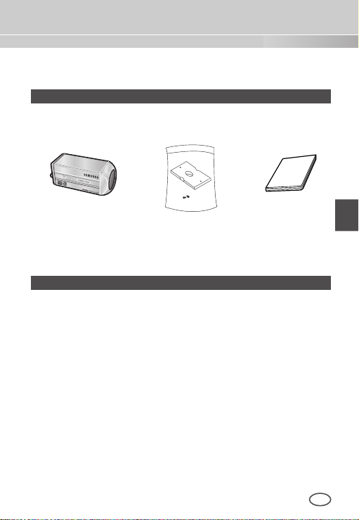
Checking the contents of the package
Make sure that the following items are included in the package.
Camera Camera Holder
(Power Adapter)
2 Screws
Things to keep in mind during installation and use
n
Do not disassemble the camera on your own.
n
Always be careful when handling the camera. Do not strike the
camera by your fists or shake it. Please be careful not to be
careless when storing and operating it.
n
Do not place or operate the camera in any wet environment
such as rain or wet surfaces.
n
Do not clean the camera with rough sandpaper. Please always
use a dry cloth when cleaning it.
n
Put the camera in a cool area free from direct sunlight.
Otherwise, the camera may be damaged.
User's Manual

Installing the Camera
❚
To install and use the camera, rst prepare the following cables.
Power Adapter Cable (sold separately)
The requirements for the power adapter, which connects to the
camera’s POWER IN terminal, are as follows:
- SCC-C4233(P)/C4235(P) : DC 12V 600mA
- SCC-C4333(P)/C4335(P) : AC 24V 300mA
DC 12V 600mA
Video Cable
Use a BNC cable, such as the one shown below, to connect the
camera’s VIDEO OUT to the monitor.
12
 Loading...