

Page 1
320X POWER ZOOM WDR CAMERA
SCC-C4207(P)/C4307(P)
Part : AB68-00544A(00)
Printed in China
Owner’s Instructions
Gebrauchsanleitung
Guide d’utilisation
Guía del usuario
Istruzioni per l’uso
✽ Be sure to read the "Safety Precautions" in this manual
to ensure correct use and operation of this product.
E
D
F
Es
I
Page 2
Important Safety Instructions
Safety Precautions
1. Read these instructions.
2. Keep these instructions.
3. Heed all warnings.
4. Follow all instructions.
5. Do not use this apparatus near water.
6. Clean only with dry cloth.
7. Do not block any ventilation openings, Install in
accordance with the manufacturer's instructions.
8. Do not install near any heat sources such as radiators,
heat registers, or other apparatus (including amplifiers) that
produce heat.
9. Do not defeat the safety purpose of the polarized or
grounding- type plug. A polarized plug has two blades with
one wider than the other.
A grounding type plug has two blades and a third
grounding prong.
The wide blade or the third prong are provided for your
safety. If the provided plug does not fit into your outlet,
consult an electrician for replacement of the obsolete
outlet.
10. Protect the power cord from being walked on or pinched
particularly at plugs, convenience receptacles, and the
point where they exit from the apparatus.
11. Only use attachments/accessories specified by the
manufacturer.
12. Use only with cart, stand, tripod, bracket, or table specified
by the manufacturer, or sold with the apparatus.
13. Unplug this apparatus. When a cart is used, use caution
when moving the cart/apparatus combination to avoid
injury from tip-over.
14. Refer all servicing to qualified service personnel. Servicing
is required when the apparatus has been damaged in any
way, such as power-supply cord or plug is damaged, liquid
has been spilled or objects have fallen into the apparatus
the apparatus has been exposed to rain or moisture, does
not operate normally, or has been dropped.
1
The purpose of safety precautions is to prevent accidental
injury or property damage. Always observe all safety
precautions.
❖ The precautions are divided into "Warnings" and
"Cautions" as distinguished below:
Warning
Ignoring this precaution
may result in death or
serious injury.
Caution
Ignoring this precaution
may result in injury or
damage to property.
Warnings
1. Be sure to use only the standard adapter which is
specified in the specification sheet.
Using any other adapter could cause fire, electrical
shock, or damage to the product.
2. Check the external connection terminals first before
connecting the power source and signal wires.
Connect the alarm signal wires to the alarm terminals.
Connect the DC12V power adapter to the SCCC4207(P) power input, making
sure that the currect polarity is observed.
Connect the DC12V or AC24V power adapter to the
SCC-C4307(P) power input.
3. Do not connect multiple cameras to a single adapter.
(Exceeding the capacity may cause abnormal heat
generation or fire.)
E
2
Page 3

4. Securely plug the power cord into the power receptacle.
(A loose connection may result in fire.)
5. When mounting the camera on a wall or ceiling, fasten it
safely and securely. (A falling camera may cause
personal injury.)
6. Do not place conductive objects (e.g., screwdrivers,
coins, and metal things) or containers filled with water on
top of the camera.
(Serious injury may result from fire, electrical shock, or
falling objects.)
7. Do not install the unit in humid, dusty, or sooty locations.
(Doing so may cause fire or electrical shock.)
8. If any unusual smells or smoke come from the unit, stop
using the product. In such case, immediately disconnect
the power source and contact the service center.
(Continued use in such a condition may cause fire or
electrical shock.)
9. If this product fails to operate normally, contact the store
of purchase or your nearest service center. Never
disassemble or modify this product in any way.
(Problems caused by unauthorized user disassembly or
repairs are not covered by your warranty.)
10. When cleaning, do not spray water directly onto parts of
the product. (Doing so may cause fire or electrical
shock.) Gently wipe the surface with a dry cloth. Never
use detergents or chemical cleaners on the product, as
this may result in discoloration of surface or cause
damage to the finish.
Cautions
1. Do not drop objects on the product or apply strong shock
to it. Keep away from a location subject to excessive
vibration or magnetic interference.
2. Do not install in a location subject to high temperature,
low temperature, or high humidity. (Doing so may cause
fire or electrical shock.)
3. Avoid a location which is exposed to direct sunlight, or
near heat sources such as heaters or radiators.
(Neglecting to do so may result in a risk of fire.)
4. If you want to relocate the already installed product, be
sure to turn off the power before moving or reinstalling it.
5. Install in a well-ventilated location.
6. Remove the power plug from the outlet when there is a
lightning storm. (Neglecting to do so may cause fire or
damage to the product.)
E
3
4
Page 4

FCC Statement
This device complies with Part 15 of the FCC Rules.
Operation is subject to the following two conditions:
(1) This device may not cause harmful interference, and
(2)
This device must accept any interference received,
including interference that may cause undesired operation.
Note:
This equipment has been tested and found to comply with
the limits for Class B digital devices, pursuant to Part 15 of
the FCC rules. These limits are designed to provide
reasonable protection against harmful interference in a
residential installation. This equipment generates, uses and
can radiate radio frequency energy and, if not installed and
used in accordance with the instructions, may cause harmful
interference to radio communications. However, there is no
guarantee that interference will not occur in a particular
installation. If this equipment does cause harmful
interference to radio or television reception, which can be
determined by turning the equipment off and on, the user is
encouraged to try to correct the interference by one or more
of the following measures:
- Reorient or relocate the receiving antenna
- Increase the separation between the equipment and
receiver
- Connect the equipment into an outlet on a circuit different
from that to which the receiver is connected
- Consult the dealer or an experienced radio/TV technician
for help Use of shielded cable is required to comply with
Class B limits in Subpart B of Part 15 of the FCC rules.
Do not make any changes or modifications to the
equipment unless otherwise specified in the manual.
If such changes or modifications should be made, you
could be required to stop operation of the equipment.
Contents
1. Overview.............................................................7
2. Part Names and Functions ...............................8
3. Installation........................................................11
Checking the Package Contents .......................11
Preparing the Cables ........................................12
Connecting the Cables ......................................13
4. Navigating the Setup Menu.............................15
Structure of the Setup Menu .............................15
- CAMERA ID.....................................................16
- IRIS..................................................................16
- SHUTTER........................................................20
- AGC/MOTION ................................................21
- WHITE BAL .....................................................22
- FOCUS MODE ................................................23
- MOTION DET ..................................................23
- COLOR / BW...................................................25
- PRIVACY.........................................................27
- SPECIAL .........................................................28
- PRESET ..........................................................31
- EXIT.................................................................32
5. Product Specification .....................................33
E
5
6
Page 5
Overview
REMOTE RS-485 PWR IN
1
This is a state-of-art WDR zoom camera which employed the
x32 zoom lens and digital zoom IC to monitor up to 320 times
as large as an original image.
SCC-C4207(P)/C4307(P) has the following functions.
●
WDR for distinct photographing of both bright and dark
parts of an image.
●
DAY/NIGHT to raise the sensitivity by automatic
conversion into the White & Black mode at night or in poor
illumination environment.
●
Low - Light Surveillance function that enables image
capture even under extremely low light conditions.
●
White Balance function that provides accurate color
rendition under any light conditions.
●
BLC function that enables effective back light
compensation even under a spotlight or a very bright
incident light.
●
Auto Focus function that automatically tracks and focuses
on the moving subject.
●
Privacy Zone function to hide a special area for privacy
protection.
●
RS485/ Wired remote control function.
Broadcast System
●
SCC-C4207/4307 : NTSC System
●
SCC-C4207P/4307P : PAL System
Power System/Power Consumption
●
SCC-C4207(P): DC 12V/5.5W
●
SCC-C4307(P): AC 24V, DC 12V/6W
7
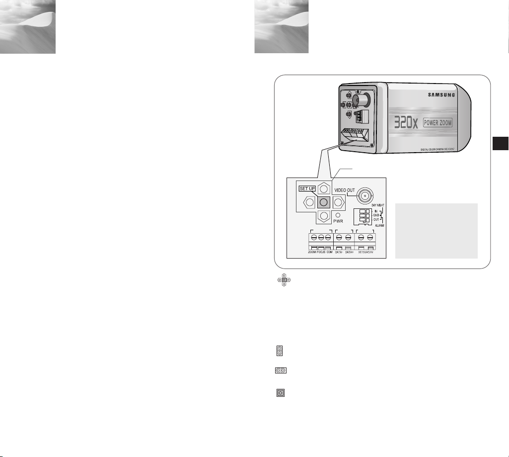
Part Names and Functions
2
SET-UP button
Instead of “POWER”, “DC IN”
is writtern in SCC-C4207(P).
Instead of “POWER”, “PWR
IN” and instead of “GND”,
“DC12&AC24V” is writtern in
SCC-C4307(P).
SET-UP button
The function of the SET-UP button varies depending on
whether you are currently in Normal Operation mode (i.e.,
the Setup Menu is not displayed) or Setup Menu mode.
In Normal Operation Mode
✔
- UP/ DOWN buttons : Use as the ZOOM Tele button
and the ZOOM Wide button respectively.
- LEFT/ RIGHT buttons : Use as the FOCUS Near
button and the FOCUS Far button respectively.
- SET- UP button: Use to enter the Setup Menu.
Hold the SET- UP button for longer than 3 seconds to
enter the Setup Menu.
Press the [SET UP] switch shortly (within 1 sec.) to
start the AF function.
E
8
Page 6
In Setup Menu Mode
✔
- UP/ DOWN buttons: Use to move the cursor up or down.
- LEFT/ RIGHT buttons: Use to move the cursor left or
right, or to sequentially view the values that can be
assigned to a parameter.
- ENTER button: Use to select a Sub Menu item, and to
accept the current value.
ZOOM/ FOCUS REMOTE terminals
This port is used for ZOOM/FOCUS, MENU CONTROL,
HOME RETURN, and AF by using an external controller.
Depending on the input condition, 4 modes, A, B, C, and
D are available. (SPECIAL - CTRL TYPE)
(Operation Voltage Range : +3V~+13V, -3V~-13V)
When the voltage is supplied to either ZOOM or FOCUS port,
1)
Code
Function
❖ 1
A
B
C
D
TELE(Up)
ZOOM Port
-6V
-6V
+6V
+6V
WIDE(Down)
+6V
+6V
-6V
-6V
NEAR(Left)
FOCUS Port
-6V
+6V
-6V
+6V
❖ 1: During MENU OFF, controls ZOOM/FOCUS and
during MENU ON, changes the direction, Up, Down,
Left, and Right.
2) When the voltage is supplied to both ports
Code
Function
A
B
C
D
ENTER/AF ❖ 2
ZOOM Port
-6V
-6V
+6V
+6V
FOCUS Port
-6V
+6V
-6V
+6V
HOME RETURN ❖ 3
ZOOM Port
+6V
+6V
-6V
-6V
FOCUS Port
❖ 2: For short voltage supply during MENU OFF,
executes AF and for more than 2 second
❖ 3: For more than 2 second long voltage supply, moves
to the PRESET 0(HOME) position.
FAR(Right)
+6V
-6V
+6V
-6V
+6V
-6V
+6V
-6V
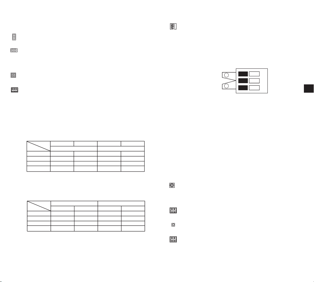
DAY/NIGHT External Signal Input & Alarm Signal
Output
This is a function to receive the external DAY/NIGHT
signal from the sensor(option) and convert the signal into
BW. An alarm signal is output from this terminal when the
MOTION DET mode is activated or BW mode is activated.
DAY/NIGHT IN
ALARM OUT
GND
1
2
Connect an external sensor to the DAY/NIGHT terminal
as shown in
then connect any external device such as
➀
a buzzer or lamp to the ALARM terminal as shown in ➁.
The ALARM output terminal is an open collector with the
following capacity: DC 16V and 100mA.
OFF : Open contact
ON : Below 100mA
The DAY/NIGHT input terminal has the input of DC 5V
pull-up and over 0.2mA.
OFF : Open contact
ON : Closed contact
VIDEO OUT terminal
Connect the monitor's VIDEO IN. The video signal from
the camera is transmitted to the monitor via this terminal.
RS485 terminal
RS485 remote control terminal.
Power LED
Lights when power is on.
POWER IN terminal
Plug in the power adapter here.
E
109
Page 7
Installation
3
Preparing the Cables
Before Installation
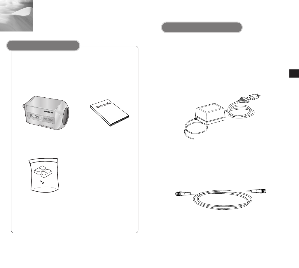
Checking the Package Contents
Make sure that the following accessories are included in
the package.
SCC-C4207(P)/4307(P)
Mount Adapter
Screw (2)
Terminal Block
User's Guide
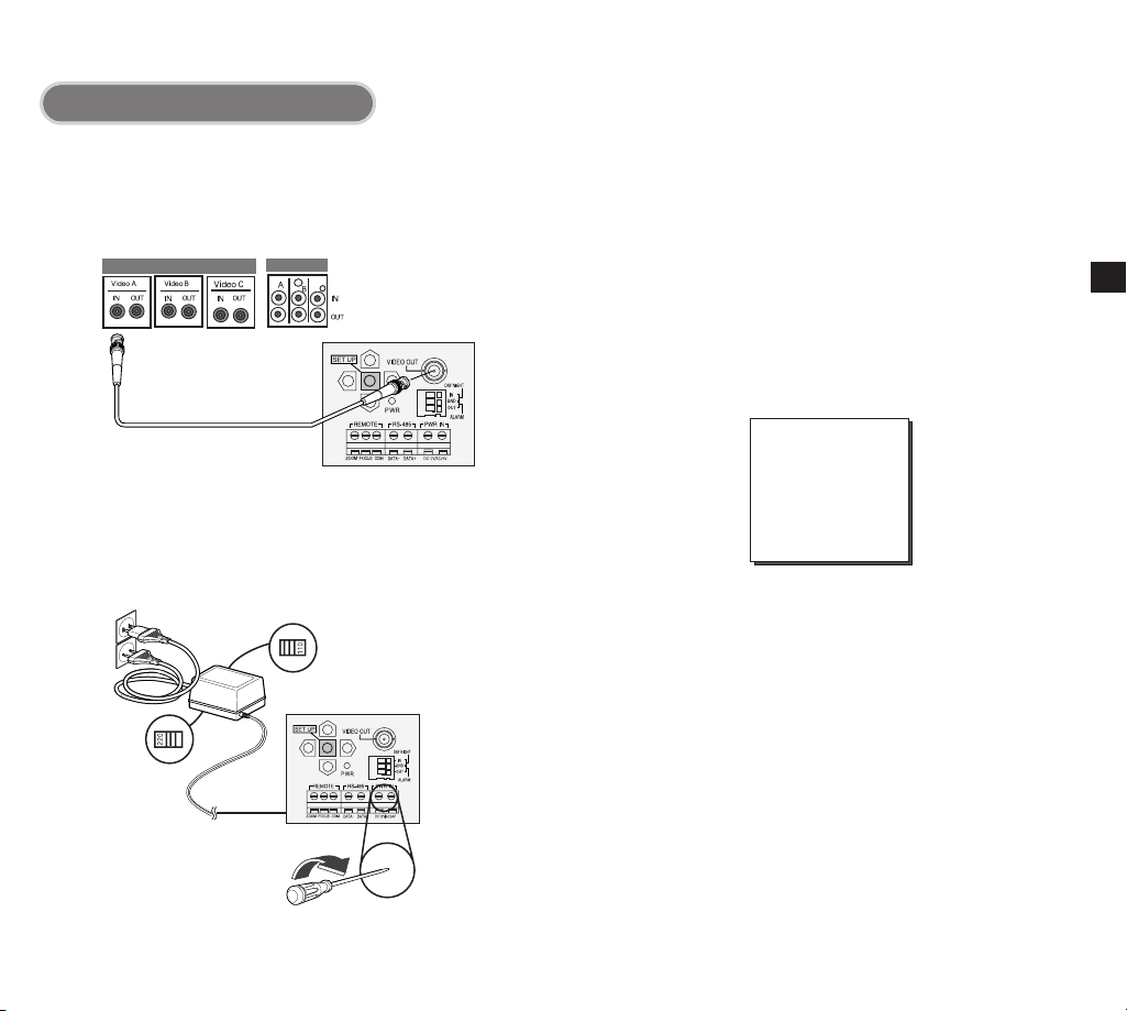
To install and use the camera, first prepare the following
cables.
The requirements for the power adapter, which connects to
the camera's POWER IN terminal, are as follows:
●
SCC-C4207(P) : DC12V 600mA
●
SCC-C4307(P) : AC24V 300mA
Video Cable
Use a BNC cable, such as the one shown below, to connect
the camera's VIDEO OUT to the monitor.
DC12V 600mA
E
11
12
Page 8
Connecting the Cables
1. Connect one end of the BNC cable to the VIDEO OUT.
2. Connect the other end of the BNC cable to the VIDEO IN
of the monitor.
Video terminals on the back
of the monitor
BNC cable
3.
Plug in the power adapter. Use a "minus" screwdriver to
connect one part of the power adapter, which consists of
two lines, to the POWER terminal of the camera as follows :
POWER SELECTION switch
underneath the power adapte
POWER SELECTION
switch underneath the
power adapte
4. Determine the type of power supply and set the POWER
SELECTION switch accordingly. Next, plug the power
adapter into a wall outlet.
The requirements for the power adapter for each model are
as follows:
●
SCC-C4207(P) : DC12V 600mA
●
SCC-C4307(P) : AC24V 300mA
DC12V 600mA
5. If the camera operates normally, the following screen will
be displayed for 5 seconds and then disappears.
SAMSUNG PROTOCOL
ADDRESS 0
TYPE
BAUD RATE 9600
LENS OK
ROM VER 1.000
EEP VER 1.000
❖
ROM VER and EEP VER may change without notice.
6. The requirements for RS485 control is as follows :
●
Signaling Speed: 9600 bps
●
Data Bit : 8 bits
●
Stop Bit : 1 bit
●
Parity Bit : none
RS-485, HALF
E
13
14
Page 9
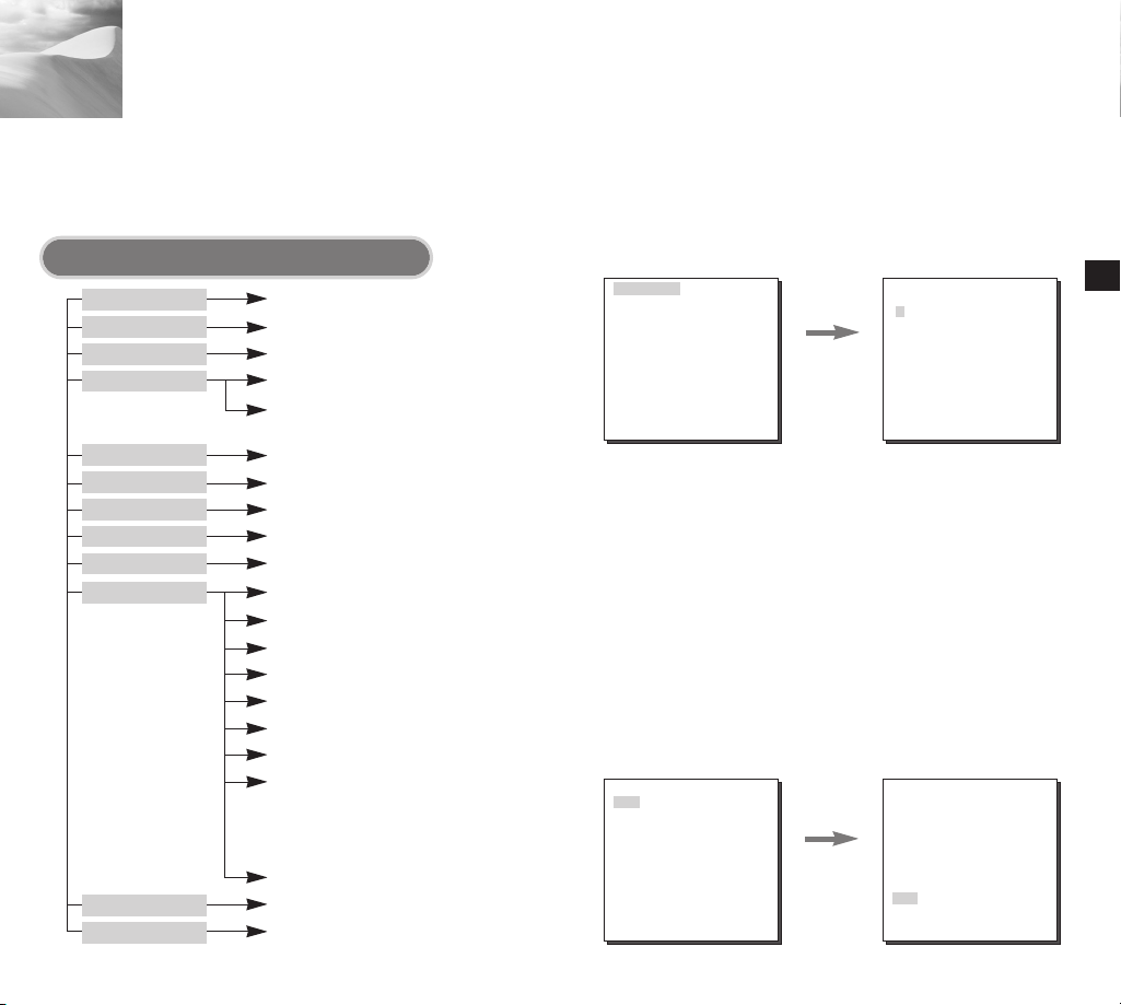
Navigating the Setup Menu
4
In this chapter, we will take a look at the menu system of the
SCC-C4207(P),C4307(P). First, we will take a look at the
structure of the Setup Menu and then describe the functions
of each menu item in the menu.
Structure of the Setup Menu
CAMERA ID
IRIS
SHUTTER
AGC/MOTION
WHITE BAL
FOCUS MODE
MOTION DET
COLOR/BW
PRIVACY
SPECIAL
PRESET
EXIT
15
❖ V-SYNC menu is only available in SCC-C4307.
OFF/ON...
ALC.../WDR.../MANU...
OFF/1/100 ~ 1/10K/AUTO X2~X160
OFF/LOW/HIGH(AGC)
S.SLOW/SLOW/NORMAL/
FAST/F.FAST(MOTION)
ATW1/ATW2/AWC/MANU...
ONEAF/MF
OFF/ON...
COLOR.../BW.../AUTO.../EXT...
OFF/ON...
...
POSI/NEGA +/DIS OFF
REVERSE OFF
DETAIL ( 1)-IY-LEVEL ( 0)|-------C-LEVEL ( 0)|--------
OTHER SET ...
LANGUAGE/CTRL TYPE/
RS-485/SYSTEM INFO/
V-SYNC(❖)
RET
...
CAMERA ID
❙
In the CAMERA ID menu, you may designate the CAMERA
ID to be displayed in the monitor connected to a camera. Set
the CAMERA ID menu to ON... and press [ENTER] and the
CAMERA ID setup submenu will appear. The CAMERA ID
may be created by up to 20 digits by using alphabets,
numbers, and some special texts served by the submenu
screen. You may locate the designated CAMERA ID on your
own by using the LOCATION... submenu.
CAMERA ID ON...
IRIS ALC...
SHUTTER OFF
AGC LOW
WHITE BAL ATW1
FOCUS MODE ONEAF
MOTION DET OFF
COLOR/BW COLOR...
PRIVACY OFF
SPECIAL ...
PRESET ...
EXIT QUIT
IRIS
❙
ALC
✔
Press the
ENTER
button.
(CAMERA ID)
ABCDE F GH I JKL
MNO PQ R S TUVWX
YZ0 1 2345 6 789
. ; ! - +*() /
SP
❿❿➛➛
SP
LOCATION...
RET
......................
Select ALC... from the IRIS menu and press [ENTER]
and the BLC(Back Light Compensation) setup submenu
will appear. If you use a general camera to photograph a
subject under backlight or bright illumination, the subject
will be shown dark on the monitor due to the backlight.
BLC(Back Light Compensation) is used to prevent such a
backlight problem to secure distinct images under bright
illumination. Using the [Left, Right] keys, you can set up
BOTTOM…, TOP…, LEFT…, RIGHT…, CENTER… 5
preset areas and the USER…function that can directly
set the areas. For example, for the items in the BLC
menu, you can confirm the preset BOTTOM area by
pressing [ENTER] key in the BOTTOM… status.
CAMERA ID OFF
IRIS ALC...
SHUTTER OFF
AGC LOW
WHITE BAL ATW1
FOCUS MODE ONEAF
MOTION DET OFF
COLOR/BW COLOR...
PRIVACY ...
SPECIAL ...
PRESET ...
EXIT QUIT
Press the
ENTER
button.
(IRIS/ALC)
BLC OFF
LEVEL (00) ----I---RET
E
16
Page 10
(IRIS/ALC)
Press the
BLC BOTTOM...
LEVEL (0) ----I---RET
ENTER
button.
For items in the BLC menu, the user can set the size and location of
the BLC area by pressing [ENTER] key after put the cursor on
USER… using the [Left, Right] key. For SIZE items, you can use the
[Up, Down, Left, Right] key to designate the SIZE, and then press the
[ENTER] key. You can set the location for areas using the [Up, Down,
Left, Right] key in the LOCATION.
WDR
✔
WDR(Wide Dynamic Range) enlarges the advantage of a
screen, mostly effective photographing both indoor and
outdoor subjects simultaneously. In short, both subjects
can be distinctly revived. Select WDR... and press
[ENTER] to set up WDR LEVEL and FLICKERLESS.
CAMERA ID OFF
IRIS WDR...
SHUTTER OFF
AGC LOW
WHITE BAL ATW1
FOCUS MODE ONEAF
MOTION DET OFF
COLOR/BW COLOR...
PRIVACY OFF
SPECIAL ...
PRESET ...
EXIT QUIT
Press the
ENTER
button.
(IRIS/WDR)
LEVEL1 L --- I --- H
LEVEL2 L --- I --- H
FLICKERLESS OFF
RET
E
(IRIS/ALC)
SIZE
Press the
BLC USER...
LEVEL (0) ----I---RET
SIZE
ENTER
button.
LOCATION
SIZE
Press the
ENTER
LOCATION
button.
LOCATION
Use [Left, Right] key in the LEVEL menu to control the video
output level(brightness).
- LEVEL 1 : Controls the shutter speed while WDR
operates.
- LEVEL 2 : Controls the whole brightness while WDR
operates.
- FLIKERLESS : This is for preventing flicker on the
screen when NTSC system is used in 50HZ power
supply region and PAL system is used in 60HZ power
supply region. That is to prevent shaking on the screen
resulted from the discordance of the vertical sync
frequency and the flicker frequency of the illumination.
While this menu is ON, the electronic shutter is fixed to
1/100sec (NTSC) or 1/120 sec (PAL).
1817
Page 11
MANU
✔
When you press [ENTER] key after selecting MANU in the
IRIS item, an additional screen appears in which you can set
manually opening or closing the IRIS.
CAMERA ID OFF
IRIS MANU...
SHUTTER OFF
AGC LOW
WHITE BAL ATW1
FOCUS MODE ONEAF
MOTION DET OFF
COLOR/BW COLOR...
PRIVACY ...
SPECIAL ...
PRESET ...
EXIT QUIT
Press the
ENTER
button.
(MANUAL)
LEVEL (00) ----I---RET
SHUTTER
❙
In the SHUTTER menu, you may determine the fast
electronic shutter speed or slow AUTO shutter speed. The
fast electronic shutter supports 7 speeds from 1/100(1/120)
sec. to 1/10K sec. to photograph a bright and quick moving
image. The slow AUTO shutter supports about 10 speed
from x2 to x160 to make an image projected to the screen
more distinct and brighter by selecting the slow shutter
speed. If you want the camera to sense the brightness and
adjust the shutter speed accordingly, select a menu
commencing with Slow AUTO Shutter. When SHUTTER is
set to AUTO, AGC will be replaced with MOTION.
CAMERA ID OFF
IRIS ALC...
SHUTTER OFF
AGC LOW
WHITE BAL ATW1
FOCUS MODE ONEAF
MOTION DET OFF
COLOR/BW COLOR.. .
PRIVACY OFF
SPECIAL ...
PRESET ...
EXIT QUIT
E
19
If you keep pressing and ➞ in the SHUTTER menu, the
➞
speed will change in the following sequence.
➞
OFF ➞ AUTOX2 ➞ AUTOX4 ➞ AUTOX6 ➞ AUTOX8 ➞
AUTOX12 ➞ AUTOX16 ➞ AUTOX20 ➞ AUTOX40 ➞ AUTOX80
➞ AUTOX160 ➞ OFF ➞ 1/100(120) ➞ 1/250 ➞ 1/500 ➞ 1/1000
➞ 1/2000 ➞ 1/4000 ➞ 1/10K ➞ OFF
❖ When the IRIS mode is set to WDR, only the following
modes are available.
OFF ➞ AUTOX2 ➞ AUTOX4 ➞ AUTOX6 ➞ AUTOX8 ➞
➞
AUTOX12 ➞ AUTOX16 ➞ AUTOX20 ➞ AUTOX40 ➞ AUTOX80
➞ AUTOX160 ➞ OFF
20
Page 12
AGC/MOTION
❙
In the AGC (Automatic Gain Control) option, you can specify
whether to automatically control the GAIN when the obtained
video is below a certain level of brightness because it was
recorded under insufficient lighting. To automatically control
the GAIN, set the AGC option to LOW or HIGH. Otherwise,
set it to OFF. If the you set the AGC option to LOW, the
maximum GAIN of the AGC will be set to low, and if set to
HIGH, the maximum GAIN will be set to high.
If the SHUTTER option is set to an auto low-speed, the AGC
option will change to the MOTION option. In the MOTION
option, use the LEFT and RIGHT buttons to select from S.S,
SLOW, NORMAL, FAST, and F.F.
CAMERA ID OFF
IRIS ALC...
SHUTTER OFF
AGC LOW
WHITE BAL ATW1
FOCUS MODE ONEAF
MOTION DET OFF
COLOR/BW COLOR...
PRIVACY OFF
SPECIAL ...
PRESET ...
EXIT QUIT
<AGC>
CAMERA ID ON...
IRIS ALC...
SHUTTER AUTOX2
MOTION S.SLOW
WHITE BAL ATW1
FOCUS MODE ONEAF
MOTION DET OFF
COLOR/BW COLOR...
PRIVACY OFF
SPECIAL ...
PRESET ...
EXIT QUIT
<MOTION>
WHITE BAL
❙
You can select one of four modes for white balance adjustment as
follows:
- ATW1/ATW2(Auto-Tracing White Balance Mode): In these
modes, the color temperature is monitored continuously and
thereby white balance is set automatically. The following are the
approximate supported color temperature ranges in these modes.
ATW1 : 2500K ~ 9300K(✻1)
ATW2 : 2000K ~ 10000K(Mode recommended for sodium
lighting)(✻2)
E
✻ 1. If the color temperature is out of this range in ATW1 mode,
proper white balance may not be obtained. In that case,
select ATW2 mode.
✻ 2. In ATW2 mode, if one color is dominated in the shooted area,
the color can be displayed differently. Therefore, select the
mode which is appropriate for the environment.
- AWC(Auto-Tracing White Balance Control): In this mode, accurate
white balance is obtained by pressing [ENTER] while having a
white paper in front of the camera. White Balance data will be
maintained after set it once. AWC mode is best in locations where
the color temperature of light source is constant.
- MANU : If WHITE BAL menu is set to MANU mode, the user can
set the white Balance considering the current illumination. Select
MANU item and press [ENTER], the sub screen where you can
select Manual White Balance will be shown. Use the left/right
keys to select 3200K, 5600K or OFF(USER) mode in the
PRESET menu.
3200K : Set color temperature to 3200K
✔
5600K : Set color temperature to 5600K
✔
USER : Choose out a proper value from the RED and BLUE
✔
graph for color and temperature setup.
(MANU)
21
PRESET OFF(USER)..
RED (80) ----I---BLUE (80) ----I---RET
22
Page 13
FOCUS MODE
❙
In the FOCUS MODE MENU, the Focus method can be set
to ONEAF(One Auto Focus), or MF(Manual Focus).
ONEAF : In the ONEAF mode, it automatically sets the
✔
focus after the zoom moves, and operates as the
same in the MF mode if the zoom does not move.
MF : You can manually adjust the focus.
✔
CAMERA ID OFF
IRIS ALC...
SHUTTER OFF
AGC LOW
WHITE BAL ATW1
FOCUS MODE ONEAF
MOTION DET OFF
COLOR/BW COLOR.. .
PRIVACY OFF
SPECIAL ...
PRESET ...
EXIT QUIT
❖
The ONEAF setting can be selected only when OFF,
1/100(1/120)~1/10K, AUTO X2 is selected for the SHUTTER
menu. Any Other SHUTTER setting(AUTO X4~AUTO X160)
causes MF to be selected automatically for the FOCUS
MODE menu.
❖
ONEAF function may not possible withe types of objects listed
below. For such objects, focus manually.
- High intensity objects or objects illuminated with low lighting
- Obejects shot through wet or dirty glass
- Pictures that are a mixture of distant and nearby objects
- White alls and other single-color objects
- Venetian blinds and other horizontally striped objects
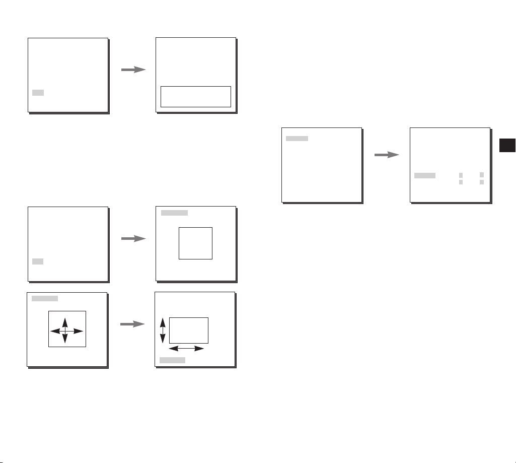
MOTION DET
❙
MOTION DET detects any motion. Set up this function
during no human movement to detect break-in. Once
detected, an ALARM signal will be given for 5 seconds. As
MOTION DET detects any motion, so it can set up the
motion detection sensitivity. Select ON... and press [ENTER]
and the MOTION DET submenu screen will appear.
23
CAMERA ID OFF
IRIS ALC...
SHUTTER OFF
AGC LOW
WHITE BAL ATW1
FOCUS MODE ONEAF
MOTION DET ON...
COLOR/BW COLOR.. .
PRIVACY ...
SPECIAL ...
PRESET ...
EXIT QUIT
Press the
ENTER
button.
(MOTION DET)
AREA PRESET...
SENSITIVITY L---I---H
RET
If you select ON and press the ENTER button, the MOTION
DET screen will come up. You can set the AREA to which the
Motion Detection function will be applied to either PRESET or
USER. If you set the AREA option to PRESET, the Motion
Detection function will be applied to the areas preset as factory
defaults. If you set the AREA option to USER and press the
ENTER button, you can change the area size and position and
select the area where you want to apply the Motion Detection
function. You can specify the size of the area by using the UP,
DOWN, LEFT, and RIGHT buttons. If the area is not flashing,
press the ENTER button. When the area starts flashing, use the
UP, DOWN, LEFT and RIGHT buttons to specify the location of
the area. Use the ENTER button and the UP, DOWN, LEFT,
and RIGHT buttons to specify the size of the area and to
position the area. Press the ENTER button again to exit the
AREA setting menu. You can use the SENSITIVITY option to
set the motion detection sensitivity. The higher the setting, the
more sensitive the motion detection.
(MOTION DET)
Press the
ENTER
AREA USER...
SENSITIVITY L---I---H
RET
❖
MOTION detection function operates based on the
button.
SIZE
LOCATION
brightness change within the setup region. Therefore,
erroneous operation may occur depending on the brightness
difference between the background and the object that is
being taken, or the status of the area setup, etc.
24
E
Page 14
COLOR / BW
❙
COLOR/BW turns IR(Infrared) Filter on or off. In the poor
illumination environment, turns IR Filter off to raise the
sensitivity to the same level as an black-and-white camera while
in the good illumination environment, turns it on to convert to the
COLOR mode in the normal screen condition to lower the
sensitivity.
COLOR
✔
This is the IR Filter ON mode with a normal color screen.
You can press the [Enter] key to set the COLOR GAIN
LEVEL. And when the AGC function is on, you can set the
AGC COLOER LEVEL.
CAMERA ID OFF
IRIS ALC...
SHUTTER OFF
AGC LOW
WHITE BAL ATW1
FOCUS MODE ONEAF
MOTION DET OFF
COLOR/BW COLOR...
PRIVACY ...
SPECIAL ...
PRESET ...
EXIT QUIT
BW...
✔
Press the
ENTER
button.
(COLOR)
GAIN (0)I-------AGC COLOR (0)----I---RET
This is the IR Filter OFF mode, black-and-white (with the
same sensitivity as a black-and-white camera). Select BW...
and press [Enter] and the BW submenu will appear. You
may determine to sent out BURST signals by ON or OFF
setting in this submenu.
❖
WHITE BAL will be marked --- so that setup is unavailable.
CAMERA ID OFF
IRIS ALC...
SHUTTER OFF
AGC LOW
WHITE BAL --FOCUS MODE ONEAF
MOTION DET OFF
COLOR/BW BW...
PRIVACY OFF
SPECIAL ...
PRESET ...
EXIT QUIT
Press the
ENTER
button.
(BW)
BURST OFF
RET
AUTO...
✔
Depending on illumination, it is automatically switched to
the COLOR or BW mode. In the poor illumination
environment, turns IR Filter off to convert to the Black-andWhite mode for better sensitivity and in the good
illumination environment, turns it on to convert to the
COLOR mode for worse sensitivity. Select AUTO and press
[Enter] and the AUTO BW submenu will appear to control
the BW level. Depending on ON or OFF, the BURST signal
may output or no. It also sets up the duration for conversion
and the brightness level for the conversion from the COLOR
mode to the BW mode. Duration options are 10Sec.,
30Sec., 1Min., and 5Min.. In the BW mode, the WHITE BAL
menu will be marked --- to make setup unavailable.
CAMERA ID OFF
IRIS ALC...
SHUTTER OFF
AGC --WHITE BAL ATW1
FOCUS MODE ONEAF
MOTION DET OFF
COLOR/BW AUTO...
PRIVACY OFF
SPECIAL ...
PRESET ...
EXIT QUIT
Press the
ENTER
button.
(AUTO)
BURST ON
LEVEL MEDIUM
DURATION S ---I--- L
RET
- ALARM ON : It sends out signals through the ALARM output
port in the BW mode.
ALARM OFF : The ALARM output port is synchronized with the
MOTION DET finction regardiess of the COLOR/BW mode.
- BURST ON : The color burst signal is output together with
black and white composite video signal.
BURST OFF : The color burst signal is not output.
-
LEVEL : You can set the brightness level that changes from
COLOR mode to BW mode in 3 steps : LOW, MEDIUM, and HIGH.
- DWELL TIME : Set the HOLDING time for switching
between COLOR and BW mode depending the changes in
the amount of light. You can set the HOLDING time to 10sec
(S), 30sec, 60sec, or 300sec( L).
❖ In AUTO mode, AGC will operates in high speed mode, and
you cannot change it manually, as it is indicated by "---".
E
25
26
Page 15
EXT...
✔
This menu automatically converts the COLOR Mode into
the BW Mode or vice versa depending on illumination with
an external sensor. If you select the EXIT menu and press
the [Enter] key, the EXTERNAL BW submenu will appear
on the menu screen. You will be able to send out the
BURST signal by turning on or off in this menu.
CAMERA ID OFF
IRIS ALC...
SHUTTER OFF
AGC LOW
WHITE BAL ATW1
FOCUS MODE ONEAF
MOTION DET OFF
COLOR/BW EXT...
PRIVACY OFF
SPECIAL ...
PRESET ...
EXIT QUIT
PRIVACY
❙
Press the
ENTER
button.
(EXTERNAL BW)
BURST ON
RET
This function designates an area that may violate PRIVACY
and hides it when the camera shoots a screen including the
area to protect Privacy. Up to 8 PRIVACY ZONEs are
available for setup. After PRIVACY menu setup, press
ENTER to enter the PRIVACY MAP screen. Now, press
UP/DOWN/LEFT/RIGHT key to choose one out of PRIVACY
0~7 and press ENTER to enter the PRIVACY setup menu.
CAMERA ID OFF
IRIS ALC…
SHUTTER OFF
AGC --WHITE BAL ATW1
FOCUS MODE ONEAF
MOTION DET OFF
COLOR/BW AUTO…
PRIVACY OFF
SPECIAL …
PRESET …
EXIT QUIT
Press the
ENTER
button.
(PRIVACY MAP)
0 1 2 3
4 5 6 7
RET
27
PRIVACY NO. 0
POSITION SET ON...
Press the
ENTER
SIZE …
LOCATION …
button.
EXIT QUIT
You shall set up the position of ZOOM/FOCUS in the
PRIVACY ZONE area from the POSITION SET menu. Press
E
UP/DOWN/LEFT/RIGHT key to size the PRIVACY ZONE
area from the SIZE menu. Press UP/DOWN/LEFT/RIGHT
key to locate the PRIVACY ZONE area from the LOCATION
menu.
❖
The rim of the screen cannot be hidden by the
PRIVACY ZONE area. Please be careful for setup.
SPECIAL
❙
In SPECIAL menu, you can set the settings related to the
VIDEO signals and various additional functions.
CAMERA ID OFF
IRIS ALC...
SHUTTER OFF
AGC LOW
WHITE BAL ATW1
FOCUS MODE ONEAF
MOTION DET OFF
COLOR/BW COLOR...
PRIVACY OFF
SPECIAL ...
PRESET ...
EXIT QUIT
Press the
ENTER
button.
(SPECIAL)
POSI/NEGA +
DIS OFF
REVERSE OFF
DETAIL (0)--IY-LEVEL (0)I-------C-LEVEL (0)I-------OTHER SET ...
RET
- POSI/NEGA : Output as it is or mirror the video brightness signal.
- DIS : Digital Image Stabilization. Compensates hand shivering
errors.
❖ It is recommended to deactivate the DIS function in the
no vibration environment.
- REVERSE : Mirrors video signals horizontally, vertically, or both.
- DETAIL : Controls the horizontal or vertical distinction.
- Y-LEVEL : It is used to set the levels for the Sync signal and the
entire brightness signal of the video signal.
28
Page 16

- C-LEVEL: It is used to set the levels for the Burst signal
and the entire colour signal of the video signal.
- OTHER SET
In OTHER SET menu, you can adjust LANGUAGE, CTRL
TYPE, ZOOM SPEED, D-ZOON, RS-485, SYSTEM
INFO..., and V-SYNC function, etc. When you press
[ENTER] key from OTHER SET menu, the OTHER SET
additional menu screen appear.
(SPECIAL)
POSI/NEGA +
DIS OFF
REVERSE OFF
DETAIL (0)--IY-LEVEL (0)I-------C-LEVEL (0)I-------OTHER SET ...
RET
❖
V-SYNC menu is only available in SCC-C4307.
(OTHER SET)
LANGUAGE ENGLISH
CTRL TYPE A
ZOOM SPEED 4
D-ZOOM OFF
RS-485 ...
SYSTEM INFO ...
V-SYNC INT
RET
- LANGUAGE : Selects English/French/German/Spanish/
Italian OSD menu.
- CTRL TYPE : By inputting the wire remote port, you may
set up the mode, A, B, C, or D.
Code
Item
Tele
A
B
C
D
-6V
-6V
+6V
+6V
Wide
+6V
+6V
-6V
-6V
Far
+6V
-6V
+6V
-6V
Near
-6V
+6V
-6V
+6V
- ZOOM SPEED : Use [Left, Right] key in the ZOOM SPEED
menu to set the speed as follows.
- ZOOM SPEED 1 : About 17Sec. from X 1 to X 32(Slowest)
- ZOOM SPEED 2 : About 10Sec. from X 1 to X 32(Slow)
- ZOOM SPEED 3 : About 6Sec. from X 1 to X 32(Fast)
- ZOOM SPEED 4 : About 3Sec. from X 1 to X 32(Fastest)
- D-ZOOM : Sets up the Digital Zoom magnification ratio up
to x10.
- RS-485 : Sets up RS-485 Communication Protocol,
29
Address, and Baud Rate.
(OTHER SET)
LANGUAGE ENGLISH
CTRL TYPE A
ZOOM SPEED 4
D-ZOOM OFF
RS-485 ...
SYSTEM INFO ...
V-SYNC INT
RET
Press the
ENTER
button.
(RS-485)
PROTOCOL SAMSUNG
BAUD RATE 9600
ADDRESS 0
RET
- SYSTEM INFO : You can confirm settings related to the
RS-485 communication, product serial number, and the
software version.
(OTHER SET)
LANGUAGE ENGLISH
CTRL TYPE A
ZOOM SPEED 4
D-ZOOM OFF
RS-485 ...
SYSTEM INFO ...
V-SYNC INT
RET
Press the
ENTER
button.
(SYSTEM INFO)
ROM VER 1.000
EEP VER 1.000
PROTOCOL SAMSUNG
ADDRESS 0
TYPE RS-485, HALF
BAUD RATE 9600
SERIAL NO 000000000000000
RET
- V-SYNC : INT shall be selected to use internal
synchronization. LINE... is used to synchronize several
camera phases for the multi camera operation by using an
external signal(AC signal). As there may be a slight deviation
between sets, adjusts PHASE to overcome this handicap.
When you use AC power source, V-SYNC is available.
Select LINE... and press [ENTER] and the PHASE control
submenu will appear. The PHASE control ranges from -106H
to +106H as for NTSC and from -138H to +138H as for PAL.
❖
When a DC power is supplied, V-SYNC menu will be displayed
as --- and you cannot make any settings.
(OTHER SET)
LANGUAGE ENGLISH
CTRL TYPE A
ZOOM SPEED OFF
D-ZOOM OFF
RS-485 ...
SYSTEM INFO ...
V-SYNC LINE...
RET
Press the
ENTER
button.
(LINE LOCK)
PHASE (-106)----I---RET
30
E
Page 17

PRESET
❙
Select the PRESET menu and press [ENTER] and the
PRESET MAP submenu screen will appear.
(PRESET MAP)
0 H 1 2 3 4
56789
10 11 12 13 14
15 16 17 18 19
20 21 22 23 24
25 26 27 28 29
30 31 RET
HOME RETURN OFF
EXIT QUIT
Press the
ENTER
button.
PRESET NO. 0
POSITION SET ...
PRESET ID OFF
EXIT QUIT
Select the PRESET number and press [ENTER] and the
above screen will appear.
POSITION SET :
✔
Memorizes the position of ZOOM or
FOCUS.
PRESET ID :
✔
Designates the ID on the basis of the
PRESET position as the CAMERA ID.
❖ HOME RETURN automatically returns to the HOME
position should there is no key input for a certain time.
The HOME position is set to PRESET 0 if it is saved or
Off if not.
HOME RETURN Time Setup
➞
OFF ➞ 1MIN ➞ 2MIN ➞ 3~60MIN ➞ 2 HOUR ➞ 3~12 HOUR
EXIT
❙
The EXIT menu is used to terminate the CAMERA SETUP
menu.
QUIT : Select to ignore any changes you have made and
✔
restore the previously saved settings.
SAVE : Select to save the settings that have been
✔
changed so far.
PRESET : Ignores any change and returns to the default of
✔
the CAMERA menu as set for the product delivery.
CAMERA ID OFF
IRIS ALC...
SHUTTER OFF
AGC LOW
WHITE BAL ATW1
FOCUS MODE ONEAF
MOTION DET OFF
COLOR/BW COLOR...
PRIVACY OFF
SPECIAL ...
PRESET ...
EXIT QUIT
E
31
32
Page 18

Product Specification
5
SCC-C4207/C4307
Item Description
Product Type
Power Supply
Voltage
Power Consumption
Broadcast System
Imaging Device
Effective Pixe
Scanning Method
Line Frequency
Synchronization
Method
Resolution
S/N Ratio
Minimum Scene
Illumination
Dynamic Range
Color Temp.
Signal Output
Lens
Remote Control
Alarm
Operating Temp.
Operating Humidity
Dimensions
Weight
Zoom Lens Built-in WDR Color Camera(NTSC TYPE)
- SCC-C4207 : DC 12V±10%
- SCC-C4307
- SCC-C4207 : 5.5W
- SCC-C4307 : 6W
- NTSC Standard Color System
- 1/4 inch WDR compatible Exview HAD CCD
- 768(H) x 494(V)
- 525 Line, 2:1 Interlace
- SCC-C4207
Horizontal : 15,734 Hz (INT)
Vertical : 59.94 Hz (INT)
- SCC-C4307
Horizontal : 15,734 Hz(INT), 15,750 Hz(L/L)
Vertical : 59.94 Hz(INT), 60 Hz(L/L)
-SCC-C4207 : Internal Only
-SCC-C4307 : Internal/Line-Lock
- 480 TV Lines
- 50dB(AGC OFF)
- Color : 0.2Lux (SENS UP X4) 0.005Lux (SENS UP X160)
B/W : 0.07Lux (SENS UP X4) 0.002Lux (SENS UP X160)
-
- Max 128
- ATW1/ATW2/AWC/Manual MODE
(3200K, 5600K, R/B Gain Adjustment)
- Composite Video Out : 1.0 Vp-p 75ohms/BNC
32x Zoom Lens in a single unit
-
- Focal length : 3.55 to 113 mm
- Aperture : F1.69(Wide), F4.17(Tele)
- Auto Focus
- Tele/Wide(ZOOM), Near/Far(FOCUS),
Iris Open/Close
- Alarm Output: 1 Out (Motion Detection)
-10°C ~ +50°C
- ~90%
- SCC-C4207 : 59.5 X 60.5 X 115.7 mm
- SCC-C4307 : 59.5 X 60.5 X 149.9 mm
- SCC-C4207 : 390g
- SCC-C4307 : 515g
: DC 12V±10%
AC 24V±10% (60Hz±0.3Hz)
Remark
SCC-C4207P/C4307P
Item Description
Product Type
Power Supply
Voltage
Power Consumption
Broadcast System
Imaging Device
Effective Pixe
Scanning Method
Line Frequency
Synchronization
Method
Resolution
S/N Ratio
Minimum Scene
Illumination
Dynamic Range
Color Temp.
Signal Output
Lens
Remote Control
Alarm
Operating Temp.
Operating Humidity
Dimensions
Weight
Zoom Lens Built-in WDR Color Camera(PAL TYPE)
- SCC-C4207P : DC 12V±10%
- SCC-C4307P
- SCC-C4207P : 5.5W
- SCC-C4307P : 6W
- PAL Standard Color System
- 1/4 inch WDR compatible Exview HAD CCD
- 752(H) x 582(V)
- 625 Line, 2:1 Interlace
- SCC-C4207P
Horizontal : 15,625 Hz (INT)
Vertical : 50 Hz (INT)
- SCC-C4307P
Horizontal : 15,625 Hz(INT), 15,625 Hz(L/L)
Vertical : 50 Hz(INT), 50 Hz(L/L)
-SCC-C4207P : Internal Only
-SCC-C4307P : Internal/Line-Lock
- 480 TV Lines
- 50dB(AGC OFF)
- Color : 0.2Lux (SENS UP X4) 0.005Lux (SENS UP X160)
B/W : 0.07Lux (SENS UP X4) 0.002Lux (SENS UP X160)
-
- Max 128
- ATW1/ATW2/AWC/Manual MODE
(3200K, 5600K, R/B Gain Adjustment)
- Composite Video Out : 1.0 Vp-p 75ohms/BNC
32x Zoom Lens in a single unit
-
- Focal length : 3.55 to 113 mm
- Aperture : F1.69(Wide), F4.17(Tele)
- Auto Focus
- Tele/Wide(ZOOM), Near/Far(FOCUS),
Iris Open/Close
- Alarm Output: 1 Out (Motion Detection)
-10°C ~ +50°C
- ~90%
- SCC-C4207 : 59.5 X 60.5 X 115.7 mm
- SCC-C4307 : 59.5 X 60.5 X 149.9 mm
- SCC-C4207 : 390g
- SCC-C4307 : 515g
: DC 12V±10%
AC 24V±10% (50Hz±0.3Hz)
Remark
E
33
34
Page 19
Correct Disposal of This Product
(Waste Electrical & Electronic
Equipment)
(Applicable in the European Union and other European
countries with separate collection systems)
This marking shown on the product or its literature, indicates
that it should not be disposed with other household wastes at
the end of its working life. To prevent possible harm to the
environment or human health from uncontrolled waste
disposal, please separate this from other types of wastes and
recycle it responsibly to promote the sustainable reuse of
material resources.
Household users should contact either the retailer where they
purchased this product, or their local government office, for
details of where and how they can take this item for
environmentally safe recycling.
Business users should contact their supplier and check the
terms and conditions of the purchase contract. This product
should not be mixed with other commercial wastes for
disposal.
Memo
Page 20
320X POWER ZOOM WDR KAMERA
SCC-C4207(P)/C4307(P)
Gebrauchsanleitung
D
✽ Die “Sicherheitshinweise” in diesem Handbuch sorgfältig
lesen, damit Sie dieses Produkt korrekt benutzen und
betreiben können.
Page 21
Sicherheitshinweise
Ziel dieser Information ist es, den ordnungsgemäßen Gebrauch
dieses Geräts sicherzustellen und dadurch Gefahren oder
Sachbeschädigungen zu vermeiden. Bitte befolgen Sie alle
Anweisungen.
❖
Die Hinweise sind in “Achtung” und “Warnung” wie unten geteilt.
Warnung
Die Nichtbeachung eines
Warnhinweises kann zum
Tode oder zu schweren
Verletzungenführen.
Achtung
Die Nichtbeachtung eines mit
Achtung gekennzeichneten
Hinweises kann zu Verletzungen
und Sachschaden führen.
Warnung
1. Achten Sie darauf, daß Sie nur den mitgelieferten Adapter
verwenden. Die Verwendung eines anderen Adapters als des
mitgelieferten kann Feuer, einen Stromschlag oder die
Beschädigung des Geräts verursachen.
Beim Anschließen der Netz- und Signalkabel müßen Sie
2.
zuerst die externen Anschlußbuchsen überprüft werden.
Schließen Sie die Alarmsignalkabeladern an die
Alarmanschlüße an.
Der DC12V Netzadapter an die
anschließen und achten Sie dabei auf die richtige Polarität.
Schließen Sie der DC12V oder AC24V Netzadapter an den
SCC-C4307(P)
3. Schließen Sie nicht mehrere Kameras an einen Adapter an.
(Wird die Kapazität überschritten, kann es zu einer anormalen
Wärmeentwicklung oder Feuer verursachen.)
4. Stecken Sie das Neztkabel fest in die Steckdose ein.
(Ein loser Anschluß kann Feuer verursachen.)
Stromeingang an.
SCC-C4207(P)
Netzsteckdose
5. Bei der Wand - oder Deckeninstallation bringen Sie die
Kamera sicher und fest an.
(Fällt die Kamera herunter, kann es zur Verletzung von
Personen kommen.)
6. Plazieren Sie keine leitfähigen Gegenstände (wie z.B.
Schraubenzieher, Münzen und metallene Objekte) oder mit
Wasser gefüllte Behälter auf der Kamera.
(Das kann zur Verletzung von Personen durch Feuer,
Stromschlag oder herunterfallende Gegenstände führen.)
7. Die Kamera darf nicht an einem rußigen, staubigen oder
feuchten Ort installiert werden.
(Andernfalls besteht die Gefahr eines Brandes oder
Stromschlags.)
8. Beim Auftreten eines ungewöhnlichen Geruchs oder einer
Rauchentwicklung, die vom Gerät ausgehen, ziehen Sie
unverzüglich das Netzkabel aus der Steckdose und wenden
Sie sich an Ihr Kundendienstzentrum.
(Die Fortsetzung des Gebrauchs kann in diesem Fall zu
Feuer oder einem elektrischen Schlag führen.)
9. Sollte das Gerät nicht störungfrei funktionieren, setzen Sie
sich mit Ihrem Händler oder dem nächsten
Kundendienstzentrum in Verbindung. Das Gerät darf niemals
in keiner Weise zerlegt oder modifiziert werden.
(Keine Haftung für die Probleme übernimmt werden, die durch
unbefugte Abänderungen oder einen Reparaturversuch
herbeigeführt sind.)
10. Beim Reinigen darf Wasser niemals direkt auf die Geräteteile
gelangen. (Andernfalls besteht die Gefahr eines Brandes oder
Stromschlags.)Die Oberfläche kann mit einem trockenen
Tuch abgewischt werden. Verwenden Sie für das Gerät keine
Reinigungsmittel oder chemischen Reiniger, da sich durch
solch Mittel die Farbe ablösen und der Oberflächenüberzug
beschädigt werden kann.
D
1
2
Page 22
Inhalt
Achtungen
1. Lassen Sie keine Gegenstände auf das Gerät fallen, und
setzen Sie es einen starken Stößen aus. Setzen Sie die
Kamera keinen Starken Vibrationen oder magnetischen
Störfeldern aus.
2. Die Kamera darf nicht an Orten mit hohen Temperaturen
bzw .tiefen Temperaturen oder hoher Luftfeuchtigkeit
installiert werden.
(Andernfalls besteht die Gefahr eines Brandes oder
Stromschlags.)
3. Installieren Sie das Gerät nicht in der Nähe von
Wärmequellen, wie z.B. einem Heizgerät oder Heizkärper,
und an Orten, an denen es direktem Sonnenlicht
ausgesetzt ist. (Hier besteht Feuergefahr.)
4. Wenn Sie die bereits installierte Kamera an einen anderen
Ort verlegen wollen, achten Sie darauf, die Kamera
auszuschalten, bevor Sie sie abnehmen oder neu
installieren.
5. Die Installation sollte an einer gut belüfteten Stelle erfolgen.
6. Ziehen Sie bei einem Gewitter den Netzstecken.
(Die Nichtbeachtung kann zu Feuer oder einer
Beschädigung des Geräts führen.)
1. Übersicht ................................................................................ 5
2. Bezeichnung der Teile und ihrer Funktionen ..................... 6
3. Installation ............................................................................... 9
Überprüfung des Lieferumfangs ........................................... 9
Vorbereitung der Kabel ....................................................... 10
Anschluß der Kabel ............................................................. 11
4. Übersicht über das Einstellmenu ....................................... 12
Aufbau des Einstellmenus ................................................... 12
- KAMERA ID ....................................................................... 15
- BLENDE ............................................................................ 15
- SHUTTER ........................................................................ 17
- AGC/BEWEGUNG............................................................. 18
- WEISSABGL ..................................................................... 19
- FOKUS MODE................................................................... 20
- AKTIVITAET ...................................................................... 20
- FARBE/S/W ....................................................................... 22
- PRIVAT .............................................................................. 24
- SPEZIAL ............................................................................ 25
- PRESET ............................................................................ 28
- AUSGANG ........................................................................ 29
Produkt Spezifikation
5.
........................................................30
D
3 4
Page 23
Ü
REMOTE RS-485 PWR IN
1
bersicht
Dieses ist eine State-Of-Art WDR Zoom Kamera, die das
x32 Objektiv Zoom und Digital Zoom IC einsetzte, um bis
320mal so groß wie ein ursprüngliches Bild zu überwachen.
SCC-C4207(P)/4307(P) hat die folgenden Funktionen.
●
WDR für das eindeutige Fotografieren der hellen und
dunklen Teile eines Bildes.
●
COLOR/BW, durch automatische Umwandlung in den
weißen und schwarzen Modus nachts oder in schlechtes
Beleuchtung Umgebung, um die Empfindlichkeit zu
erhöhen.
●
Die Low - Light - Überwachungsfunktion ermöglicht die
Aufnahme bewegter Objekte bei sehr geringer Beleuchtung.
●
Die Weße Abgleichsfunktion sorgt für eine exakte
Farbwiedergabe bei einer beliebigen Lichtquelle.
●
Die GLK-funktion erlaubt eine wirkungswolle Gegenlicht
Kompensation auch an Orten mit einem Scheinwerfer oder
starkem Lichteinfall.
●
Die Autofokus Funktion verfolgt und fokussiert automatisch die
bewegte Objekte.
●
Privat Zone Funktion, die den bestemmten Bereich für das
Privatleben nicht sichtbar lässt,
●
RS485/ Wired remote control function.
Übertragung System
●
SCC-C4207/4307 : NTSC
●
SCC-C4207P/4307P : PAL
System
System
Power System / Power Verbrauch
●
SCC-C4207(P): DC 12V/5.5W
●
SCC-C4307(P): AC 24V, DC 12V/6W
5
Bezeichnung der Teile und ihrer
2
Funktionen
Bouton SET-UP
“POWER”ist gleich “DC IN”bei
SCC-C4207(P)
gleich “PWR IN”ber
SCC-C4307(P).
“GND” und “+12V”ist gleich
“DC12&AC24V”bei
SCC-C4307(P).
SET-UP Taste
Die Funktion der SET-UP Taste ändern sich je nachdem, ob sich
die Kamera gerade in der Normalbetriebsart (wo das
Einstellmenu nicht auf dem Bildschirm angezeigt wird) oder
Setup Menu Mode befindet.
In normaler Betriebsmode
✔
Die Richtungstasten AUF/AB : Diese Tasten fungiert als
ZOOM Tele Taste und als ZOOM Breit Taste.
Die Richtungstasten LINKS/RECHTS: Diese Tasten fungiert
als FOKUS Weit Taste und FOKUS Nah Taste.
Setup Taste : Diese Taste ist für das Einstellmenu.
Die SETUP Taste länger als 3 Sekunden drücken bleiben,
das Setup Menu zu befinden.
Drücken Sie kurz (1 Sek. lang) die Taste [SET UP]
(Einstellungen), um die AF-Funktion (Autofokus) zu starten.
. “POWER”ist
6
D
Page 24
In Setup Menu Mode
✔
Die Richtungstasten AUF/AB : Mit diesen Tasten wird der Cursor
auf - und abwärts bewegt.
Die Richtungtasten LINKS/RECHTS : Mit diesen Tasten wird der
Cursor nach links oder rechts bewegt oder werden die Werte, die in
jedem Einstellmenu zugewiesen werden können, der Reihe nach
angezeigt.
Die Taste ENTER : Mit dieser Taste wird ein Einstellmenu mit dem
jeweiligen Untermenu ausgewählt und der aktuelle Wert akzeptiert.
ZOOM/FOKUS FERN - anschlußklemme
Dieses Port wird für ZOOM/FOKUS, MENÜ CONTROL, HOME
RETURN und AF mit der Verwendung von externem Steuergerät
verwendet.
Abhängig von dem Eingang Zustand sind 4 Modi, A, B, C und D
verfügbar. (SPEZIELL - CTRL TYP)
(Betrieb Spannungsbereich: +3V~+13V, -3V~-13V)
1)
Wenn die Spannung entweder an ZOOM- oder FOKUS Port geliefert wird
Artikel
TELE(Oben)
❖ 1
Code
A
B
C
D
❖
1: Während MENÜ AUS steuert ZOOM/FOKUS und während
ZOOM Port
-6V
-6V
+6V
+6V
BREIT(Unter)
+6V
+6V
-6V
-6V
NAH(Links)
FOKUS Port
-6V
+6V
-6V
+6V
FERN(Rechts)
+6V
-6V
+6V
-6V
MENÜ EIN ändert die Richtung, oben, unten, links und
rechts.
2) Wenn die Spannung an beide Ports geliefert wird
Artikel
Code
A
B
C
D
❖
2: Für kurze Spannungsversorgung während des MENÜ
ENTER/AF ❖ 2
ZOOM Port
-6V
-6V
+6V
+6V
FOKUS Port
-6V
+6V
-6V
+6V
HOME RETURN ❖ 3
ZOOM Port
+6V
+6V
-6V
-6V
FOKUS Port
+6V
-6V
+6V
-6V
AUS, führt AF und für mehr als 2 Sekunden durch
❖
3: Für mehr als 2 Sekunden lang Spannungsversorgung
bewegt sich zu der PRESET 0(HOME) Position.
TAG/NACHT Außensignal Input & ALARM Signal
Ausgabe
Diese Funktion empfangt das außen TAG/NACHT Signal
von dem Außenlicht Sensor (Option) und zum SW
umwandeln lassen. Ein Alarm signal ist ein Ausgang von
diesem Terminal wenn die AKTIVITAET Mode aktiviert ist,
oder die S/W Mode aktiviert.
DAY/NIGHT IN
ALARM OUT
GND
1
2
Ein Außensensor zum TAG/NACHT Terminal anschließen,
wie Nummer ➀zeigt. Die Außerengerate wie ein Summer
oder eine Lampe zum ALARM Terminal anschließen, wie
Nummer ➁zeigt. Der ALARM Ausgabe Terminal ist ein
offene Einnehmer mit dem folgenden Fassungsvermogen ;
DC 16V und 100 mA
AUS : Offener Kontakt
EIN : Unter 100mA
Der TAG/NACHT Input Terminal hat ein Input DC 5V Pullup, uber 0.2mA.
AUS : Offener Kontakt
EIN : Geschloßener KOntakt
VIDEO OUT Anschlußklemme
Schließen Sie VIDEO IN in Monitor an. Das Videosignal
von der Kamera wird zum Monitor über diese Klemme
getragen.
RS485 Anschlußklemme
RS485 Fernbedienungsklemme
POWER LED
Bei POWER auf EIN leuchtet.
POWER IN Anschlußklemme
Der Netzadapter hier anschließen.
D
87
Page 25

Installation
3
Vorbereitung der Kabel
Vor der Installation
Überpüfung des Lieferumfangs
Überprüfen Sie bitte, ob die folgenden Zubehörteile im
Lieferumfang enthalten sind.
SCC-C4207(P)/4307(P)
Montier-adapter
Schrauben(2)
Anschlußklemme
Block
Bedienungsanleitung
Folgende Kabel werden für die Installation und den Einsatz der
Kamera benötigt.
Der Netzadapter, der an die POWER IN Buchse der Kamera
angeschloßen wird, sind wie folgt :
●
SCC-C4207(P)
●
SCC-C4307(P)
Video Kabel
Das Kabel, das den VIDEO OUT der Kamera mit dem Monitor
verbindet, ist ein BNC Kabel.
: DC 12V 600mA
: AC 24V 300mA
DC 12V 600mA
D
9
10
Page 26

Anschluß der Kabel
1. Schließen Sie zuerst das eine Ende des BNC Kabels an den
VIDEO OUT an.
2. Schließen Sie als nächstes das andere Ende des BNC Kabels
an die VIDEO IN des Monitors an.
Videobuchse auf der Hinterseite
des Monitors BNC Kabel
BNC Kabel
3. Schließen Sie dann den Netzadapter an. Verwenden Sie einen
“Schlitz” Schraubenzieher, um das zweiadrige Ende des
Netzadapterkabels an den POWER Anschlußklemme der
Kamera wie folgt anzuschließen
POWER AUSWAHL schaltet
unter den Netzadapter um.
POWER AUSWAHL
schaltet unter den
Netzadapter um.
4. Wählen Sie die Art der Stromquelle, die Sie benutzen wollen,
und stellen Sie die entsprechende POWER AUSWAHL Taste
ein. Stecken Sie anschließend den Netzadpter am Wand-ablauf
ein.
Der Netzadapter für jedes Model sind wie folgt :
●
SCC-C4207(P)
●
SCC-C4307(P)
: DC 12V 600mA
: AC 24V 300mA
DC 12V 600mA
5. Wenn die Kamera normal funktioniert, erscheint der folgende
Bildschirm und wird nach 5 Sekunden wieder ausgeblendet.
SAMSUNG PROTOKOL
ADDRESSE 0
TYPE
BAUD RATE 9600
ROM VER 1.000
EEP VER 1.000
❖
ROM VER (ROM-VERSION) und EEP VER (EEP-VERSION)
RS-485, HALB
können ohne vorherige Ankündigung geändert werden.
6. Bei der RS485-Steuerung überprüfen Sie bitte Folgendes :
●
Kommunikations-geschwindigkeit : 9600 bps
●
Daten Bit : 8 Bits
●
Stopp Bit : 1 Bit
●
Parität Bit : None
D
11
12
Page 27

Übersicht über das Einstellmenu
4
In diesem Kapitel, wir werden einen Überblick über dem Menu
System des
SCC-C4207(P),C4307(P)
geben.Zuerst, wir werden
einen Überblick über den Aufbau der Einstellmenu und ihrer
Funktionen des jeden Menu Artikels geben.
Aufbau des Einstellmenu
❖ Das Menü V-SYNC ist nur im Modell SCC-C4307 verfügbar.
KAMERA ID
❙
Im KAMERA ID Menü können die KAMERA ID kennzeichnen, um im Monitor
der an eine Kamera angeschlossen wird, angezeigt zu werden. Stellen Sie das
KAMERA ID Menü auf EIN ein... und betätigen Sie die [EINGABE] Taste und
dann wird das KAMERA ID Einstellung Submenü angezeigt. Die KAMERA ID
kann durch bis 20 Stellen hergestellt werden, indem Sie Alphabete, Zahlen und
etwas spezielle Texte verwenden, die durch den Submenü Schirm gedient
werden. Sie können die gekennzeichnete KAMERA ID auf Ihre Eigene
lokalisieren, indem Sie das POSITION... Submenü verwenden.
KAMERA ID EIN ...
BLENDE ALC...
SHUTTER AUS
AGC WENI G
WEISSABGL ATW1
FOKUS MODE EINAF
AKTIVITAET AUS
FARBE/S/W FARBE...
PRIVAT AUS
SPEZIAL ...
PRESET ...
AUSGANG VERL
BLENDE
❙
ALC
✔
Die ENTER
Taste
drücken.
KAMERA ID)
A B C D E F G H I J K L
M N O P Q R S T U V W X
Y Z 0 1 2 3 4 5 6 7 8 9
. ; ! - + * ( ) /
SP
❿❿➛➛
SP
POSITION...
RUE
.....................
D
Wählen Sie ALC... vom BLENDE Menü aus und betätigen Sie die
[EINGABE] Taste, und dann wird das BLC(Gegenlicht Kompensation)
Einstellung Submenü angezeigt. Wenn Sie eine allgemeine Kamera
verwenden, um einen Gegenstand unter Gegenlicht oder Helle
Beleuchtung zu fotografieren, wird der Gebenstand wegen der Gegenlicht
dunkel auf dem Monitor dargestellt. BLC(Gegenlicht Kompensation) wird
verwendet, um solche Gegenlicht Probleme zu verhindern, und damit um
eindeutiger Bilder unter helle Beleuchtung zu sichern.
Über die Tasten [Links, Rechts] erreichen Sie die fünf voreingestellten
Bereiche OBEN…, UNTEN…, LINKS…, RECHTS… und MITTE… sowie
die Funktion BENUTZER… zur Direkteinstellung der Bereiche. Im Menü
BLC können Sie beispielsweise den Einstellungsbereich OBEN bestätigen,
indem Sie im Untermenü OBEN… die Taste [EINGABE] drücken.
KAMERA ID AUS
BLENDE ALC...
SHUTTER AUS
AGC WENI G
WEISSABGL ATW1
FOKUS MODE EINAF
AKTIVITAET AUS
FARBE/S/W FARBE...
PRIVAT AUS
SPEZIAL ...
PRESET ...
AUSGANG VERL
Die ENTER
Taste
drücken.
(BLENDE/ALC)
BLC AUS
PEGEL ( 0) ----I---RUE
1413
Page 28
(BLENDE/ALC)
Die ENTER
BLC OBEN...
PEGEL (0) ----I---RUE
Taste
drücken.
Um für Elemente im Menü BLC Größe und Position des
BLC-Bereichs festzulegen, positionieren Sie mit den Tasten
[Links, Rechts] den Cursor auf BENUTZER…, und drücken
Sie [EINGABE]. Um über GROESSE die Größe festzulegen,
verwenden Sie die Tasten [Oben, Unten, Links, Rechts],
und drücken Sie anschließend [EINGABE]. Um die Position
von Bereichen festzulegen, benutzen Sie im Untermenü
POSITION die Tasten [Oben, Unten, Links, Rechts].
(BLENDE/ALC)
BLC BENUTZER...
PEGEL (0) ----I---RUE
GROESSE
POSITION
Die ENTER
Taste
drücken.
Die ENTER
Taste
drücken.
GROESSE
POSITION
GROESSE
POSITION
WDR
✔
WDR(Wide Dynamik Range) vergrößert den Vorteil eines
Schirmes, meistens wirkungsvoll die Gegenstände, die im Innen
oder Außen sind, gleichzeitig zu fotografieren. Kurz gesagt
können beide Gegenstände deutlich wieder auferstanden
werden. Wählen Sie WDR...aus und betätigen Sie die
[EINGABE] Taste, um WDR PEGEL und FLIMMERFREI
einzustellen.
KAMERA ID AUS
BLENDE WDR...
SHUTTER AUS
AGC WENI G
WEISSABGL ATW1
FOKUS MODE EINAF
AKTIVITAET AUS
FARBE/S/W FARBE...
PRIVAT AUS
SPEZIAL ...
PRESET ...
AUSGANG VERL
Die ENTER
Taste
drücken.
(BLENDE/WDR)
PEGEL1 L --- I --- H
PEGEL2 L --- I --- H
FLIMMERFREI AUS
RUE
- PEGEL 1 : Die SHUTTER GESCHWINDIGKEIT mit der WDR
Funktion anpassen.
- PEGEL 2 : Die Helligkeit mit der WDR Funktion anpassen.
- FLIMMERFREI : Dieser Regler soll das Flimmern des Bildes
auf dem Monitor bei 60 Hz verhindern. Ein wackelndes Bild
kann durch die Unstimmigkeit der V SYNC ( Frequenz) und
der Ausleuchtung entstehen. Wenn der Regler auf Position
EIN steht, betragt die festgelegte Verschlusszeit 1/120 pro
Sekunde.
D
Verwenden Sie
und ➞im Pegel Menü, um den Video
➞
Ausgang Pegel(Helligkeit) zu steuern.
1615
Page 29

MANU
✔
Wenn Sie im Untermenü BLENDE auf MANU gehen und die
Taste [ENTER] drücken, wird ein zusätzlicher Bildschirm
angezeigt, über den Sie das Öffnen und Schließen der
BLENDE manuell einstellen können.
KAMERA ID AUS
BLENDE MANU...
SHUTTER AUS
AGC WENIG
WEISSABGL ATW1
FOKUS MODE EINAF
AKTIVITAET AUS
FARBE/S/W FARBE...
PRIVAT ...
SPEZIAL ...
PRESET ...
AUSGANG VERL
Die ENTER
Taste
drücken.
(MANUEL)
PEGEL (00) ----I---RUE
SHUTTER
❙
Im SHUTTER Menü können Sie die schnelle elektronische Shutter
Geschwindigkeit oder langsame Auto Shutter Geschwindigkeit
feststellen. Der schnelle elektronische Shutter unterstützt stützt 7
Geschwindigkeiten von 1/100(1/120) Sek. zu 1/10K Sek., um ein
helles und schnelles bewegliches Bild zu fotografieren. Der
langsame Auto Shutter unterstützt Ca. 10 Geschwindigkeit von x2
bis x160, um ein Bild deutlicher und heller zu beabsichtigen, indem
Sie die langsame Shutter Geschwindigkeit auswählen. Wenn Sie
die Kamera die Helligkeit abfragen und die Shutter Geschwindigkeit
dementsprechend justieren möchten, wählen Sie ein Menü aus,
das mit dem langsamen Auto Shutter beginnt. Wenn SHUTTER auf
D
AUTO eingestellt wird, wird AGC mit BEWEGUNG ersetzt.
KAMERA ID AUS
BLENDE ALC...
SHUTTER AUS
AGC WENI G
WEISSABGL ATW1
FOKUS MODE EINAF
AKTIVITAET AUS
FARBE/S/W FARBE...
PRIVAT AUS
SPEZIAL ...
PRESET ...
AUSGANG VERL
17
Wenn Sie
und ➞
im SHUTTER Menü gedrückt halten, wird
➞
die Geschwindigkeit in der folgenden Reihenfolge geändert.
➞
AUS ➞ AUTOX2 ➞ AUTOX4 ➞ AUTOX6 ➞ AUTOX8 ➞
AUTOX12 ➞ AUTOX16 ➞ AUTOX20 ➞ AUTOX40 ➞ AUTOX80
➞ AUTOX160 ➞ AUS ➞ 1/100(120) ➞ 1/250 ➞ 1/500 ➞ 1/1000
➞ 1/2000 ➞ 1/4000 ➞ 1/10K ➞ AUS
❖ Wenn der BLENDE Modus auf WDR eingestellt wird, sind
nur die folgenden Modi verfügbar.
AUS ➞ AUTOX2 ➞ AUTOX4 ➞ AUTOX6 ➞ AUTOX8 ➞
➞
AUTOX12 ➞ AUTOX16 ➞ AUTOX20 ➞ AUTOX40 ➞ AUTOX80
➞ AUTOX160 ➞ AUS
18
Page 30

AGC/BEWEGUNG
❙
Sie können angeben, ob die AGC (Automatische Verstärkung
Kontrolle) Option aktiviert werden soll, wenn das erhaltene Videobild
unter einer bestimmten Helligkeit-stufe liegt, weil es bei
unzureichenden Licht Verhältnissen aufgenommen wurde.Der GAIN
automatisch zu kontrollieren, stellen Sie die Option AGC zu WENIG
oder HOCH ein. Anderenfalls, zu AUS einstellen. Wenn Sie die AGC
Option zu WENIG einstellen, der maximum GAIN des AGC wird auf
Niedrig eingestellt und wenn Sie es HOCH einstellen, der maximum
GAIN wird auf Hoch eingestellt. Wenn Die Option SHUTTER zu einer
Auto Low Speed eingestellt ist, wird die Option AGC zur BEWEGUNG
Option wechseln. In der BEWEGUNG Option, mit den Tasten LINKS
und RECHTS können Sie von S.LANG, LANG, NORM, SCHN und
S.SCHN auswählen.
KAMERA ID AUS
BLENDE ALC...
SHUTTER AUS
AGC WENI G
WEISSABGL ATW1
FOKUS MODE EINAF
AKTIVITAET AUS
FARBE/S/W FARBE...
PRIVAT AUS
SPEZIAL ...
PRESET ...
AUSGANG VERL
<AGC>
KAMERA ID AUS
BLENDE ALC...
SHUTTER AUS
BEWEGUNG NORM
WEISSABGL ATW1
FOKUS MODE EINAF
AKTIVITAET AUS
FARBE/S/W FARBE...
PRIVAT AUS
SPEZIAL ...
PRESET ...
AUSGANG VERL
MOTION
>
<
WEISSABGL
❙
Für den Weißlichtabgleich sind drei Einstellungen wie folgt möglich:
-
ATW1/ATW2 (Automatischer Weißabgleich) : In diesem Modus wird
die Farbtemperatur ständig gemessen und der Weißabgleich erfolgt
automatisch. Die unterstützten Farbtemperaturen sind wie folgt.
ATW1 : 2500K ~ 9300K(✻1)
ATW2 : 2000K ~ 10000K (Modus für künstliche Beleuchtung)(✻2)
✻ 1. Wenn die Farbtemperatur außerhalb des Bereiches im ATW1
Modus liegt, kann kein optimaler Weißabgleich erfolgen.
In diesem Fall wählen Sie den ATW2 Modus.
✻ 2. Im ATW2 Modus, kann eine größere einfarbige Fläche im
D
Bild zu Farbfehlern führen. Wählen Sie somit den
entsprechenden Modus für die jeweilige Umgebung.
- AWC : In diesem Modus erfolgt der Weißabgleich in dem Sie ein
weißes Blatt Papier vor die Kamera halten und die (ENTER)
Taste betätigen. Der Weißabgleich wird somit einmal
eingemessen.
Der AWC Modus ist besonders in Bereichen mit stetig gleicher
Ausleuchtung geeignet.
- MANU : In diesem Modus kann der Weißabgleich manuell
eingestellt werden, entsprechend den Umgebungsbedingungen.
Wählen Sie MANU aus und drücken Sie die (ENTER) Taste. Die
Farbtemperatur kann nun angepasst werden. Verwenden Sie die
links/rechts Taste zur Auswahl 3200K, 5600K oder OFF
(BENUTZER) Modus im PRESET Menü.
3200K : Stellt die Farbe Temperatur auf 3200K ein.
✔
5600K : Stellt die Farbe Temperatur auf 5600K ein.
✔
BENUTZER : Wählen Sie einen Wert vom ROT und BLAU
✔
Steuerstab aus, um die Farbe Temperatur
einzustellen.
(WEISSABGL/MANUEL)
19
PRESET AUS(BENUTZER)..
ROT (80)----I---BLAU (80)----I---RUE
20
Page 31

FOKUS MODE
❙
Im FOKUS MODE-Menü kann die Fokussierung auf
EINAF(One Auto Fokus) oder MF(Manuelle Fokus)
eingestellt werden.
EINAF : Im Modus ONEAF wird der Fokus nach Änderungen
✔
der Zoomeinstellung automatisch gesetzt und
funktioniert genauso wie im Modus MF (Manueller
Fokus), wenn der Zoom nicht geändert wird.
MF : Sie können manuell die Mode Fokus einstellen.
✔
KAMERA ID AUS
BLENDE ALC...
SHUTTER AUS
AGC WENI G
WEISSABGL ATW1
FOKUS MODE EINAF
AKTIVITAET AUS
FARBE/S/W FARBE...
PRIVAT AUS
SPEZIAL ...
PRESET ...
AUSGANG VERL
❖ Die Einstellung EINAF kann nur gewählt werden, wenn im Menü SHUTTER
die Option AUS, 1/100 (1/120) bis 1/10K oder AUTO X2 ausgewählt ist.
Wenn im Menü SHUTTER eine andere Einstellung ausgewählt wird (z. B.
AUTO X4 bis AUTO X160), wird im Menü FOKUS MODE automatisch der
Modus MF aktiviert.
❖ Die automatische Fokuseinstellung mit EINAF funktioniert in den
nachstehend aufgeführten Aufnahmesituationen möglicherweise nicht.
Verwenden Sie in diesen Fällen den manuellen Fokus.
- Aufnahmen von sehr hellen oder schwach beleuchteten Objekten
- Aufnahmen von Objekten hinter nassem oder verschmutztem Glass
- Aufnahmen von weit entfernten und nahegelegenen Objekten in einem Bild
- Aufnahmen von weißen Wänden oder anderen einfarbigen Objekten
- Aufnahmen von Jalousien oder anderen horizontal gestreiften Objekten
AKTIVITAET
❙
AKTIVITAET ermittelt jede mögliche Bewegung. Stellen Sie diese
Funktion während keiner menschlichen Bewegung ein, um des
Einbruches zu ermitteln. Sobald ermittelt, wird ein ALARM Signal für 5
Sekunden dauert. Als AKTIVITAET jede mögliche Bewegung ermittelt,
also kann die Bewegung Detektion empfindlich eingestellt werden.
Wählen Sie auf EIN... aus und betätigen Sie die [EINGABE], und dann
wird der AKTIVITAET Submenü Schirm angezeigt.
21
KAMERA ID AUS
BLENDE ALC...
SHUTTER AUS
AGC WENI G
WEISSABGL ATW1
FOKUS MODE EINAF
AKTIVITAET AUS
FARBE/S/W FARBE...
PRIVAT AUS
SPEZIAL ...
PRESET ...
AUSGANG VERL
Die ENTER
Taste
drücken.
(AKTIVITAET)
BEREICH PRESET...
EMPF LI ------ H
RUE
Wenn Sie auf EIN wählen und ENTER drücken, wird das
AKTIVITAET Bild eingeblendet. Sie können BEREICH einstellen, in
dem die Bewegungsmelder-funktion zu PRESET oder BENUTZER
angewendet wird. Wenn Sie die Option EREICH zu PRESET
D
angeben wird die Bewegungsmelder-funktion auf den Bereich Preset
als werkseitige Standardeinstellung. Wenn Sie die Option BEREICH
auf BENUTZER einstellen und ENTER drücken, können Sie die
Bereichgröße und die Position ändern und die Bereich wählen wo Sie
die Bewegungsmelder-funktion anwenden möchten.Sie können die
Größe des Bereichs mit den Tasten AUF, AB, LINKS und RECHTS
angeben. Drücken Sie die Taste ENTER , wenn der Bereich nicht
blinkt. Wenn er beginnt zu blinken, können Sie jetzt mit den Tasten
AUF, AB, LINKS und RECHTS die Position des Bereichs
festlegen.Mit der Taste ENTER und die Tasten AUF, AB, LNKS und
RECHTS können Sie die Gräßen und die Position des Bereichs
festlegen. durch erneutes Drücken von ENTER verlassen Sie die
Menu BEREICH. Sie können ödie Option EMPFINDLICH verwenden,
die Bewegungsmelder-empfindlichkeit einzustellen. Je höher die
Einstellung, desto empfindlicher der Bewegungsmelder.
(AKTIVITAET)
Die ENTER
Taste
BEREICH USER...
EMPF LI ------ H
RUE
❖
Die Funktion MOTION DETECTION (AKTIVITAET) wird durch
drücken.
GROESSE
POSITION
Helligkeitswechsel innerhalb des Einstellungsbereichs aktiviert. Je
nach Helligkeitsunterschied zwischen dem Hintergrund und dem
aufgenommenem Objekt, dem Status des Einstellungsbereichs und
anderen Faktoren kann die Kamera versehentlich aktiviert werden.
22
Page 32

FARBE S/W
❙
FARBE/S/W stellt IR(Infrarot) Filter an oder ab. In schlechter
Beleuchtung Umgebung stellt IR Filter ab, um die Empfindlichkeit
zum gleichen Niveau wie eine Schwarzweiß Kamera zu erhöhen,
während es in guter Beleuchtung Umgebung, anstellt, um den
Farbe Modus in normalen Schirmzustand zu umwandeln, um die
Empfindlichkeit zu senken.
FARBE
✔
Dieses ist IR Filter EIN Modus mit einem normalen Farbe
Schirm. Zum Einstellen von FARBE GAIN PEGEL drücken
Sie die Taste [ENTER]. Wenn zudem die Funktion AGC
aktiviert ist, können Sie den Wert für AGC FARBE PEGEL
einstellen.
KAMERA ID AUS
BLENDE ALC...
SHUTTER AUS
AGC WENIG
WEISSABGL ATW1
FOKUS MODE EINAF
MOTION DET AUS
FARBE/S/W FARBE...
PRIVAT ...
SPEZIAL ...
PRESET ...
AUSGANG VERL
S/W...
✔
Die ENTER
Taste
drücken.
(FARBE)
GAIN (0)I-------AGC FARBE (0)----I---RUE
Dieses ist der IR Filter AUS Modus, Schwarzweiß (mit der
gleichen Empfindlichkeit wie eine Schwarzweiß Kamera).
Wählen Sie S/W... aus und betätigen Sie die [ENTER] Taste,
und dann wird das S/W Submenü angezeigt. Sie können
feststellen, um BURST Signale auszusenden, indem Sie EIN
oder AUS in diesem Submenü einstellen.
❖ WEISSABGLEI wird gekennzeichnet --- damit
Einstellung nicht verfügbar ist.
KAMERA ID AUS
BLENDE ALC...
SHUTTER AUS
AGC WENI G
WEISSABGL --FOKUS MODE EINAF
AKTIVITAET AUS
FARBE/S/W S/W.. .
PRIVAT AUS
SPEZIAL ...
PRESET ...
AUSGANG VERL
Die ENTER
Taste
drücken.
(S/W)
FARBTRAGER AUS
RUE
23
AUTO...
✔
Abhängig von Beleuchtung wird es automatisch zum FARBE
oder S/W Modus geschaltet. In der schlechten Beleuchtung
Umgebung, stellt IR Filter ab, um im Schwarzweiß Modus für
bessere Empfindlichkeit umzuwandeln, und in der guten
Beleuchtung Umgebung, stellt es an, um im Farbe Modus für
schlechtere Empfindlichkeit umzuwandeln. Wählen Sie AUTO
aus und betätigen Sie die [EINGABE], und dann wird AUTO
S/W Submenü angezeigt, um dem S/W Pegel zu steuern.
Abhängig von EIN oder AUS, kann das BURST Signal
ausgeben oder nicht. Es stellt auch die Dauer für Umwandlung
und das Helligkeit Pegel für die Umwandlung vom FARBE
Modus zum S/W Modus ein. Dauer Option sind 10Sek.,
30Sek., 1Min. und 5Min.. Im S/W Modus wird das
WEISSABGLEICH Menü gekennzeichnet --- um Einstellung
nicht verfügbar zu machen.
KAMERA ID AUS
BLENDE ALC...
SHUTTER AUS
AGC --WEISSABGL ATW1
FOKUS MODE EINAF
AKTIVITAET AUS
FARBE/S/W AUTO...
PRIVAT AUS
SPEZIAL ...
PRESET ...
AUSGANG VERL
Die ENTER
Taste
drücken.
- ALARM EIN : Es sendet die Signale durch die ALARM
Ausgangsbuchse in der S/W Mode.
- ALARM AUS : Die ALARM Ausgangs-buchse ist mit der
AKTIVITAET Funktion ohne Rusicht auf der FARBE S/W Mode
synchronisiert.
- FARBTRAGER EIN : Das Farbe Bruch Signal ist mit dem Schwarz
und Weiss bildeten Videosignal zusammen ausgegeben.
- FARBTRAGER AUS : Das Farbe Bruch Signal ist nicht ausgegeben.
- PEGEL : Sie konnen die Helligkeitsstufe einstellen, die von der
FARBE Mode zur S/W Mode in 3 Stufen andert: WENIG, MITTEL
und HOCH.
- SCHWELLZEIT : Die HOLDING ZEIT fur die Schaltung zwischen der
FARBE und der SW Mode je nach der Anderung in der Lichtsmenge
einstellen. Sie konnen die HOLDING ZEIT in 10Sek (S), 30Sek,
60Sek oder 300 Sek (L) einstellen.
❖
In der AUTO Mode, wird AGC in der hohen Speedmode
(AUTO)
ALARM AUS
FARBTRAGER EIN
PEGEL WENIG
ZEITRAUM S--I-L
RUE
betreiben und Sie konnen nicht es manuell andern, wie es bei
“---” angezeigt wird.
D
24
Page 33

EXT...
✔
Dieses Menu umwandelt die FARBE Mode in der SW Mode
automatisch oder umgekehrt je nach der Beleuchtung mit dem
außeren Sensor. Wenn Sie das EXT Menu wahlen und die
Taste [ENTER] drucken, wird das EXTERNAL S/W Untermenu
auf dem Menubild erscheinen. Sie konnen das BRUCH Signal
drehend auf EIN oder AUS in diesem Menu aussenden.
KAMERA ID AUS
BLENDE ALC...
SHUTTER AUS
AGC WENI G
WEISSABGL ATW1
FOKUS MODE EINAF
AKTIVITAET AUS
FARBE/S/W AUTO...
PRIVAT AUS
SPEZIAL ...
PRESET ...
AUSGANG VERL
PRIVAT
❙
Die ENTER
Taste
drücken.
(EXTERN S/W)
FARBTRAGER EIN
RUE
Diese Funktion bestimmt einen Bereich, der PRIVATLEBEN
verletzen kann und versteckt ihn, um Privatleben zu schützen,
wenn die Kamera einen Schirm einschließlich des Bereichs
aufnimmt. Bis zu den 8 PRIVAT Zonen sind für die Einstellung
verfügbar. Nach der PRIVAT Menü Einstellung, betätigen Sie
EINGABE, um den PRIVAT ZONE Schirm zu kommen. Dann
betätigen Sie die OBEN/ UNTEN/ LINKS/ RECHTS Tasten, um
eins aus PRIVAT 0~7 auszuwählen und dann betätigen Sie
EINGABE, um das PRIVATZONE PROG Menü zu kommen.
KAMERA ID AUS
BLENDE ALC…
SHUTTER AUS
AGC --WEISSABGL ATW1
FOKUS MODE EINAF
AKTIVITAET AUS
FARBE/S/W AUTO…
PRIVAT AUS
SPEZIAL …
PRESET …
AUSGANG VERL
Die ENTER
Taste
drücken.
(PRIVAT KARTE)
0 1 2 3
4 5 6 7
RUE
25
PRIVAT NR. 0
POSITIONS PROG EIN
GROESSE …
Die ENTER
POSITION …
Taste
drücken.
AUSGANG VERL
Sie stellen die Position von ZOOM/FOKUS im PRIVAT ZONE
Bereich vom POSITION PROG Menü auf. Betätigen Sie OBEN/
UNTEN/ LINKS/ RECHTS Tasten, um die Größe von PRIVAT
ZONE Bereich im GRÖSSE Menü einzustellen. Betätigen Sie
OBEN/ UNTEN/ LINKS/ RECHTS Tasten, um den PRIVAT
ZONE Bereich vom POSITION Menü zu lokalisieren.
❖
Die Rand des Schirmes kann nicht durch den PRIVAT
ZONE Bereich versteckt werden. Nehmen Sie sich bitte
für die Einstellung in Acht.
SPEZIAL
❙
Im Menü SPEZIAL können Sie die Einstellungen für die
Video-Signale sowie verschiedene Zusatzfunktionen anpassen.
KAMERA ID AUS
BLENDE ALC...
SHUTTER AUS
AGC WENIG
WEISSABGL ATW1
FOKUS MODE EINAF
AKTIVITAET AUS
FARBE/S/W FARBE...
PRIVAT AUS
SPEZIAL ...
PRESET ...
AUSGANG VERL
Die ENTER
Taste
drücken.
(SPEZIAL)
POSI/NEGA +
DIS AUS
REVERS AUS
DETAIL (0 )--IY-PEGEL (0)I-------C-PEGEL (0)I-------WEITERE PROG ...
RUE
- POSI/NEGA : gibt aus, wie es ist, oder spiegelt das Video
Helligkeit Signal.
- DIS : Digital Image Stabilisation. Gleicht Handzitternde
Störungen aus.
❖
Es wird empfohlen, DIS Funktion unter keine Ersch
ütterung Umgebung zu deaktivieren.
- REVERSE : Spiegelt Videosignale horizontal, vertikal oder beide.
- DETAIL : Steuert der horizontale oder vertikale Unterschied.
- Y-PEGEL : Hier können Sie den Pegel für das
Synchronisationssignal und für die Gesamthelligkeit
des Videosignals einstellen.
26
D
Page 34

- C-PEGEL : Hier können Sie den Pegel für das Burst-Signal
und für das gesamte Farbsignal des Videosignals
einstellen.
- WEITERE PROG
Im Menü WEITERE PROG können Sie unter anderem die
Optionen SPRACHE, CTRL TYPE, ZOOM GESCH, D-ZOOM,
RS-485, SYSTEM INFO… oder V-SYNC einstellen.
(SPEZIAL)
POSI/NEGA +
DIS AUS
REVERS AUS
DETAIL (0)--IY-PEGEL (0)I-------C-PEGEL (0)I-------WEITERE PROG ...
RUE
(WEITERE PROG)
SPRACHE DEUTSCH
CTRL TYPE A
ZOOM GESCH 4
D-ZOOM AUS
RS-485 ...
SYSTEM INFO ...
V-SYNC INT
RUE
❖ Das Menü V-SYNC ist nur im Modell SCC-C4307
verfügbar.
- SPRACHE : Wählt Englisch/Französisch/Deutsch/Spanisch/
Italienisch OSD Menü aus.
- CTRL TYPE : Indem Sie das verdraht Remote Port eingeben,
können Sie den Modus, A, B, C oder D einstellen.
Code
Artikel
Tele
A
B
C
D
-6V
-6V
+6V
+6V
Breit
+6V
+6V
-6V
-6V
Weit
+6V
-6V
+6V
-6V
Nah
-6V
+6V
-6V
+6V
- ZOOM GESCH : Verwendet [Left,Right] key im Zoom
Geschwindigkeit Menü, wie folgt einzustellen.
-ZOOM GESCH 1 : Ca. 17Sek. von X 1 zu X 32(langsamste)
-ZOOM GESCH 2 : Ca 10Sek. von X 1 zu X 32(langsam)
-ZOOM GESCH 3 : Ca 6Sek. von X 1 zu X 32(schnell)
-ZOOM SPEED 4 : Ca 3Sek. von X 1 zu X 32(schnellste)
- D-ZOOM : Stellt das Digital Zoom Vergrößerung Ratio bis zum
x10 ein.
- RS-485 : Stellt RS-485 Kommunikationsprotokoll, Adresse und
Baudrate ein.
27
(WEITERE PROG)
SPRACHE DEUTSCH
CTRL TYPE A
ZOOM GESCH 4
D-ZOOM AUS
RS-485 ...
SYSTEM INFO ...
V-SYNC INT
RUE
Die ENTER
Taste
drücken.
(RS-485)
PROTOKOLL SAMSUNG
BAUD RATE 9600
ADRESSE 0
RUE
- SYSTEM INFO : Sie können die Einstellungen für die
RS-485-Kommunikation, die Seriennummer des Geräts und die
Softwareversion bestätigen.
(WEITERE PROG)
SPRACHE DEUTSCH
CTRL TYPE A
ZOOM GESCH 4
D-ZOOM AUS
RS-485 ...
SYSTEM INFO ...
V-SYNC INT
RUE
Die ENTER
Taste
drücken.
(SYSTEM INFO)
ROM VER 1.000
EEP VER 1.000
PROTOKOLL SAMSUNG
ADRESSE 0
TYPE RS-485, HALB
BAUD RATE 9600
S/N: 000000000000000
RUE
D
- V-SYNC : INT wird ausgewählt, um interne Synchronisierung zu verwenden.
LINIE... wird verwendet, um mehrere Kameraphasen für den MultiKamerabetrieb zu synchronisieren, indem man ein externes Signal(AC Signal)
verwendet. Während es eine geringfügige Abweichung zwischen Sätzen
geben kann, justieren Sie PHASE, um dieses Handikap zu überwinden. Wenn
Sie AC Power Quelle verwenden, ist V-SYNC verfügbar. Wählen Sie LINIE...
aus und betätigen Sie die [ENTER], und dann wird das PHASE Steuer
Submenü angezeigt. Die PHASE Steuerung reicht von -106H zu +106H was
NTSC anbetrifft und von -138H zu +138H was PAL anbetrifft.
❖ Bei Gleichstromversorgung wird das Menü V-SYNC mit
dem Symbol --- angezeigt, und Sie können keine
Einstellungen vornehmen.
(WEITERE PROG)
SPRACHE DEUTSCH
CTRL TYPE A
ZOOM GESCH 4
D-ZOOM AUS
RS-485 ...
SYSTEM INFO ...
V-SYNC LINIE...
RUE
Die ENTER
Taste
drücken.
(LINIE LOCK)
FASE (- 106)I-------RUE
28
Page 35

PRESET
❙
Wählen Sie das PRESET Menü aus und betätigen Sie die
[EINGABE], und dann wird der PRESET KARTE Submenü
Schirm angezeigt.
(PRESET KARTE)
0 H 1 2 3 4
56789
10 11 12 13 14
15 16 17 18 19
20 21 22 23 24
25 26 27 28 29
30 31 RUE
HOME ZURÜCK AUS
AUSGANG VERL
Die ENTER
Taste
drücken.
PRESET NO. 0
POSITIONS PROG ...
PRESET ID AUS
AUSGANG VERL
Wählen Sie die PRESET NUMMER aus und betätigen Sie
die [EINGABE] Taste, und dann wird der oben genannten
Schirm angezeigt.
POSITION PROG.:
✔
Merkte sich die Position von ZOOM
oder von FOKUS.
PRESET ID:
✔
Kennzeichnet die ID auf der Grundlage von
PRESET Position; wie die KAMERA ID.
❖
HOME RETURN geht automatisch zur Ausgangsposition,
und sollte dort kein Taste Eingabe geben, während einer
bestimmten Zeit. Die HOME Position wird auf PRESET 0
einstellt, wenn es gespeichert wird, oder aus wenn es
nicht.
AUSGANG
❙
Das AUSGANG Menü wird verwendet, um das Kamera
Einstellung Menü zu beenden.
VERL : Übergeht alle von Ihnen vorgenommenen Veränderungen
✔
und stellt das vorherig gespeicherte Einstellmenu wieder her.
SICHERN : Speichert die Einstellungen, die bisher verändert
✔
worden sind.
✔
PRESET :
Ignoriert jede mögliche Änderung und geht zur
Default Einstellung vom KAMERA Menü, wie die
Fabrikeinstellung.
KAMERA ID AUS
BLENDE ALC...
SHUTTER AUS
AGC WENI G
WEISSABGL ATW1
FOKUS MODE EINAF
AKTIVITAET AUS
FARBE/S/W FARBE...
PRIVAT ...
SPEZIAL ...
PRESET ...
AUSGANG VERL
D
HOME RETURN Zeit Einstellung
➞
AUS ➞ 1MIN ➞ 2MIN ➞ 3~60MIN ➞ 2 HOUR ➞ 3~12 HOUR
29
30
Page 36

Produkt Spezifikation
5
SCC-C4207/C4307
Parameter Beschreibung
Produkt Typ
Spannungsquelle
Leistungsaufnahme
Fernsehnorm
Bildaufnehmer
Effektive Pixel
Abtastverfahren
Zeilenfrequenz
Synchronisationsverfa
hren
Auflösung
S/N Abstand
Minimum Szenen
Beleuchtung
Dynamic Range
Farbe Temp.
Signalausgang
Objektiv
Remote Control
Alarm
Betriebstemp.
Betriebsfeuchtigkeit
Abmessungen
Gewicht
Zoom Objektiv eingebaute WDR Farbe Kamera(NTSC TYP)
-
SCC-C4207 : DC 12V±10%
-
SCC-C4307 : DC 12V±10%
- SCC-C4207 : 5.5W
- SCC-C4307 : 6W
-
- 1/4 Zoll WDR kompatibles ExAnsicht HAD CCD
- 768(H) x 494(V)
-
- SCC-C4207
- SCC-C4307
-SCC-C4207 : Intern Nur
-SCC-C4307 : Intern/Zeilen
- 480
- 50dB(AGC AUS)
-Farbe : 0.2 Lux 0.005 Lux(Sens Up x 160)
-S/W : 0.07 Lux 0.002 Lux(Sens Up x 160)
- MAX 128
- ATW1/ATW2/AWC/Manuelles MODUS
-
- 32fach Zoom in einziger Einheit
- Brennweite : 3.55 - 113 mm
- Öffnung : F1.69 (Weit), F4.17 (Tele)
- Selbst fokus
- Tele/BREIT(ZOOM), Nah/Fern(FOKUS),
-
-10°C ~ +50°C
- ~90%
- SCC-C4207 : 59.5 X 60.5 X 115.7 mm
- SCC-C4307 : 59.5 X 60.5 X 149.9 mm
- SCC-C4207 : 390g
- SCC-C4307 : 515g
AC 24V±10% (60Hz±0.3Hz)
NTSC Standard Farbe System
525 Zeilen, 2:1 Zeilensprung
Horizontal : 15,734 Hz (INT)
Vertical : 59.94 Hz (INT)
Horizontal : 15,734 Hz (INT), 15,750 Hz (L/L)
Vertical : 59.94 Hz (INT), 60 Hz (L/L)
Fernsehzeilen
(3200K, 5600K, R/B Gain Anpassung)
Composite-Videoausgang : 1.0 Vp-p 75 ohms/BNC
Blende Öffnen/Schließen
Alarm-Ausgang : 1 Ausgang (Bewegungserkennung)
Bemerkung
SCC-C4207P/C4307P
Parameter Beschreibung
Produkt Typ
Spannungsquelle
Leistungsaufnahme
Fernsehnorm
Bildaufnehmer
Effektive Pixel
Abtastverfahren
Zeilenfrequenz
Synchronisationsverfa
hren
Auflösung
S/N Abstand
Minimum Szenen
Beleuchtung
Dynamic Range
Farbe Temp.
Signalausgang
Objektiv
Remote Control
Alarm
Betriebstemp.
Betriebsfeuchtigkeit
Abmessungen
Gewicht
Zoom Objektiv eingebaute WDR Farbe Kamera(PAL TYP)
-
SCC-C4207P : DC 12V±10%
-
SCC-C4307P : DC 12V±10%
- SCC-C4207P : 5.5W
- SCC-C4307P : 6W
-
PAL Standard Farbe System
- 1/4 Zoll WDR kompatibles ExAnsicht HAD CCD
- 752(H) x 582(V)
-
625 Zeilen, 2:1 Zeilensprung
- SCC-C4207P
Horizontal : 15,625 Hz (INT)
Vertical : 50 Hz (INT)
- SCC-C4307P
Horizontal : 15,625 Hz (INT), 15,625 Hz (L/L)
Vertical : 50 Hz (INT), 50 Hz (L/L)
-SCC-C4207P : Intern Nur
-SCC-C4307P : Intern/Zeilen
- 480
- 50dB(AGC AUS)
-Farbe: 0.2 Lux 0.005 Lux(Sens Up x 160)
-S/W : 0.07 Lux 0.002 Lux(Sens Up x 160)
- MAX 128
- ATW1/ATW2/AWC/Manuelles MODUS
(3200K, 5600K, R/B Gain Anpassung)
Composite-Videoausgang : 1.0 Vp-p 75 ohms/BNC
-
- 32fach Zoom in einziger Einheit
- Brennweite : 3.55 - 113 mm
- Öffnung : F1.69 (Weit), F4.17 (Tele)
- Selbst fokus
- Tele/BREIT(ZOOM), Nah/Fern(FOKUS),
Blende Öffnen/ Schließen
Alarm-Ausgang: 1 Ausgang (Bewegungserkennung)
-
-10°C ~ +50°C
- ~90%
- SCC-C4207 : 59.5 X 60.5 X 115.7 mm
- SCC-C4307 : 59.5 X 60.5 X 149.9 mm
- SCC-C4207 : 390g
- SCC-C4307 : 515g
AC 24V±10% (50Hz±0.3Hz)
Fernsehzeilen
Bemerkung
D
31
32
Page 37

Korrekte Entsorgung dieses
Produkts (Elektromüll)
(Anzuwenden in den Ländern der Europäischen Union und
anderen euroäischen Ländern mit einem separaten
Sammelsystem)
Die Kennzeichnung auf dem Produkt bzw. auf der
dazugehörigen Literatur gibt an, dass es nach seiner
Lebensdauer nicht zusammen mit dem normalen
Haushaltsmüll entsorgt werden darf. Entsorgen Sie dieses
Gerät bitte getrennt von anderen Abfällen, um der Umwelt
bzw. der menschlichen Gesundheit nicht durch unkontrollierte
Müllbeseitigung zu schaden. Recyceln Sie das Gerät, um die
nachhaltige Wiederverwertung von stofflichen Ressourcen zu
fördern.
Private Nutzer sollten den Händler, bei dem das Produkt
gekauft wurde, oder die zuständigen Behörden kontaktieren,
um in Erfahrung zu bringen, wie sie das Gerät auf
umweltfreundliche Weise recyceln können.
Gewerbliche Nutzer sollten sich an Ihren Lieferanten wenden
und die Bedingungen des Verkaufsvertrags konsultieren.
Dieses Produkt darf nicht zusammen mit anderem
Gewerbemüll entsorgt werden.
Hinweis
Page 38

CAMERA WDR ZOOM PUISSANT 320X
SCC-C4207(P)/C4307(P)
Guide d’utilisation
F
✽ Veuillez lire attentivement les ‘précautions de sécurité’
de ce manuel afin d’assurer une utilisation et un
fonctionnement corrects de l’appareil.
Page 39

Précautions de sécurité
Les précautions de sécurité sont des mesures à prendre pour
éviter toute blessure accidentelle ou un dommage sur l’appareil.
Veuillez toujours respecter toutes les précautions.
❖
Ces précautions comportent les mention ‘Avertissement’ et
‘Attention’ comme indiqué ci-dessous :
Avertissement
Ignorer cette précaution
peut provoquer une
blessure sérieuse voir
mortelle.
Attention
Ignorer cette précaution peut
provoquer une blessure ou
un endommagement de
l’appareil.
Avertissement
1. IN’utilisez que l’adaptateur standard précisé sur la feuille
de spécifications. L’utilisation d’un adaptateur d’un autre
type peut provoquer un incendie, un choc électrique ou un
dommage sur l’appareil.
2. IVérifiez d’abord les terminaux de connexions externes
avant de connecter le cordon d’alimentation et les câbles
signaux. Connectez les câbles signaux d’alarme aux
terminaux d’alarme. Connectez l’adaptateur de puissance
12V CC à l’entrée d’alimentation de
SCC-C4207(P)
Connectez l’adaptateur de puissance 12V CC ou 24V CA à
l’entrée d’alimentation de
3. INe connectez pas de multiples caméras à un seul
adaptateur. (Une capacité excessive peut provoquer un
échauffement anormal ou un incendie.)
en respectant la polarité.
SCC-C4307(P)
.
4. Branchez solidement le cordon d’alimentation sur le secteur.
(Une connexion lâche peut provoquer un incendie.)
5. Lors d’une installation mural ou au plafond, fixez solidement la
caméra en toute sécurité. (Une chute de la caméra peut
provoquer une blessure personnelle.)
6. Ne placez pas d’objets conducteurs (tournevis, pièces de
monnaie ou objets métalliques) ou des conteneurs remplis
d’eau au-dessus de la caméra. (Des blessures sérieuses
peuvent être provoquées par un incendie, un choc électrique
ou une chute d’objets.)
7. N’installez pas l’appareil dans des endroits humides,
poussiéreux ou couverts de suie. (Ceci peut provoquer un
incendie ou un choc électrique.)
8. En cas d’émission d’odeur ou de fumée inhabituels hors de
l’appareil, arrêtez immédiatement son fonctionnement et
débranchez le cordon d’alimentation. Contactez ensuite le
centre de service. (Une utilisation en continu dans ces
conditions peut provoquer un incendie ou un choc électrique.)
9. Si l’appareil ne fonctionne pas correctement, contactez le
centre d’achat ou votre centre de service le plus proche. En
aucun cas, vous ne devez démonter ni modifier l’appareil.
(Les problèmes causés par le démontage ou la réparation par
une personne non autorisée ne sont pas couverts par votre
garantie.)
10. Lors d’un nettoyage, évitez de vaporiser de l’eau directement
sur les parties de l’appareil. (Ceci peut provoquer un incendie
ou un choc électrique). Essuyez doucement la surface avec
un tissu sec. N’appliquez jamais de détergent ou de nettoyant
chimique sur l’appareil, car ceci peut provoquer une
décoloration endommager la surface.
F
1
2
Page 40

Sommaire
Attention
1. Ne faites pas tomber d’objet sur l’appareil et ne lui donnez
pas de choc. L’emplacement de l’appareil doit être éloigné
des l’interférences magnétique ou de vibration excessive.
2. N’installez pas l’appareil dans un endroit humide ou à une
température trop haute ou trop basse.
(Ceci peut provoquer un incendie ou un choc électrique.)
3. Evitez un emplacement exposé aux rayonnements direct
du soleil ou proche des sources de chaleur telles que les
radiateurs.
(Ne pas respecter ceci risque de provoquer un incendie.)
4. Si vous voulez déplacer un appareil déjà installé, n’oubliez
pas de le mettre hors tension avant le déplacement et la
réinstallation.
5. Installez l’appareil dans un endroit bien aéré.
6. Retirez la prise de courant lors d’un orage accompagné
d’éclairs. (Ne pas respecter ceci risque de provoquer un
incendie ou un dommage sur l’appareil.)
1. Introduction ............................................................................. 5
2. Noms et fonctions des composants .................................... 6
3. Installation ............................................................................... 9
Vérification du contenu de l’emballage ................................. 9
Préparation des câbles ........................................................ 10
Connexion des câbles ......................................................... 11
4. Utilisation du menu Setup ................................................... 13
Structure du menu Setup .................................................... 13
- CAMERA ID ...................................................................... 14
- IRIS .................................................................................... 14
- SHUTTER ......................................................................... 18
-
CAG/MOUVEMENT
BAL BLANCS
-
-
MODE FOCUS
DET MOUVE
-
-
COULEUR/N&B
PRIVEE
-
-
SPECIAL
PRESET
-
-
SORTIE
Spécifications techniques
5.
............................................................................. 24
.......................................................................... 26
........................................................................... 29
............................................................................ 30
........................................................ 19
.................................................................. 20
................................................................ 21
.................................................................... 21
............................................................... 23
................................................ 31
F
3 4
Page 41

Introduction
REMOTE RS-485 PWR IN
1
Les SCC-C4207(P)/4307(P) sont des caméras WDR zoom
ultramodernes dotées d’un objectif zoom x32 et d’un circuit
intégré avec zoom numérique permettant une surveillance
jusqu’à 320 fois plus étendue par rapport à l’image originale.
Les caméras SCC-C4207(P)/4307(P) offrent les fonctions
suivantes :
●
La fonction WDR pour une photographie distante aussi
bien du côté lumineux que le côté sombre d’une image.
●
La fonction COULEUR/NB afin d’augmenter la sensibilité
de la conversion automatique vers le mode Noir & Blanc
dans la nuit ou dans des conditions de faible éclairage.
●
Fonction ‘Surveillance en basse luminosité’ qui permet de
capturer une image même sous un éclairage extrêmement
faible.
●
Fonction ‘Balance des blancs’ qui offre une interprétation
précise des couleurs sous n’importe quel éclairage.
●
Fonction ‘CJOUR’ qui permet une compensation efficace du
contre-jour même sous un spot ou un éclairage sur scène très
lumineux.
●
Fonction ‘Focalisation automatique’ qui suit et focalise le sujet
mobile.
●
La Fonction Zone Privée permettant de verrouiller une zone
spécifique en vue de protéger la vie privée.
●
Fonction ‘RS485 / Contrôle à distance câblé’.
Système de diffusion
●
SCC-C4207/4307
●
SCC-C4207P/4307P
: Système NTSC
: Système PAL
Système d’alimentation / Consommation électrique
●
SCC-C4207(P)
●
SCC-C4307(P)
: 12V CC / 5.5W
: 24V CA, 12V CC / 6W
5
Noms et fonctions des composants
2
Bouton SET-UP
A la place de ‘POWER’,
‘DC IN’ est écrit sur
SCC-C4207(P).
A la place de ‘POWER’ et ‘GND’,
‘PWR IN’ et ‘DC12&AC24V’ sont
écrits sur
SCC-C4307(P).
Bouton SET-UP
La fonction du bouton SET-UP varie selon le mode actuel : mode
de fonctionnement normal (i.e., le menu Setup n’est pas affiché)
ou mode de menu Setup.
En mode de fonctionnement normal :
✔
- Boutons Haut / Bas : Utilisez-les comme le bouton ‘ZOOM
Tele’ et le bouton ‘ZOOM Wide’ respectivement.
- Boutons Gauche / Droite : Utilisez-les comme le bouton
‘FOCUS Near’ et le bouton ‘FOCUS Far’ respectivement.
- Bouton SET-UP : Utilisez-le pour accéder au menu Setup.
Appuyez sur le bouton SET-UP pendant plus de 3
secondes pour entrer dans le menu Setup.
Appuyez brièvement sur l'interrupteur [SET UP]
(CONFIGURATION) pour lancer la fonction AF (Mise au
point automatique).
6
F
Page 42

En mode de menu Setup :
✔
- Boutons Haut / Bas : Utilisez-les pour déplacer le curseur vers le
haut ou le bas.
- Boutons Gauche / Droite : Utilisez-les pour déplacer le curseur
vers la gauche ou la droite, ou pour voir séquentiellement les
valeurs qui peuvent être assignées à un paramètre.
- Bouton Entrée : Utilisez-le pour sélectionner le menu Setup et
pour accepter la valeur actuelle.
Terminaux à distance ZOOM / FOCUS
Ce port est utilisé pour les fonctions ZOOM/FOCUS, CONTROLE
MENU, RETOUR ACCUEIL et AF (AutoFocus) au moyen d’un
contrôleur externe. Selon la condition d’entrée, quatre modes
(A, B, C et D) sont disponibles (TYPE SPECIAL - CTRL)
(Plage de tension de fonctionnement : +3V à +13V, -3V à -13V)
1. Lorsque la tension est fournie à l’un des ports ZOOM et FOCUS.
Code
A
B
C
D
Article
❖ 1
TELE (Haut)
Port ZOOM
-6V
-6V
+6V
+6V
LARGE (Bas)
+6V
+6V
-6V
-6V
PROCHE (Gauche)
Port FOCUS
-6V
+6V
-6V
+6V
LOIN (Droit)
+6V
-6V
+6V
-6V
❖ 1: Vous pouvez régler les fonctions ZOOM/FOCUS
pendant que le MENU est réglé sur OFF, et changer
les directions Haut, Bas, Gauche et Droit pendant
que le MENU est réglé sur ON.
2) Lorsque la tension est fournie aux deux ports.
Code
A
B
C
D
Article
ENTRE/AF ❖ 2
Port ZOOM
-6V
-6V
+6V
+6V
Port FOCUS
-6V
+6V
-6V
+6V
RETOUR ACCUEIL ❖ 3
Port ZOOM
+6V
+6V
-6V
-6V
Port FOCUS
+6V
-6V
+6V
-6V
❖ 2: Pour une brève tension pendant que le MENU est
réglé sur OFF, exécutez la fonction AF pendant plus
de 2 secondes.
❖ 3: Pour une tension prolongée de plus de 2 secondes,
allez en position PRESET 0 (ACCEUIL).
Entree de signal externe JOUR/NUIT & sortie de signal
d’alarme
C’est une fonction qui permet de recevoir le signal externe
JOUR/NUIT emis par un detecteur de luminosite externe (option)
et de changer le mode de fonctionnement en noir et blanc.
Un signal d’alarme est emis de ce terminal lorsque le mode DET
MOUVE ou N&B est active.
DAY/NIGHT IN
ALARM OUT
Reliez le detecteur externe au terminal JOUR/NUIT comme le
GND
1
2
F
montre la figure ➀puis reliez l’equipement externe tel que
sonnerie ou lampe au terminal d’alarme comme le montre la figure
.
➁
La sortie d’alarme est un collecteur ouvert de puissance :
inferieur DC 16V/ inferieur 100mA.
OFF : contact ouvert
ON : inferieur a 100mA
L’entree JOUR/NUIT est de DC 5V pull-up et superieur a 0,2mA.
OFF : contact ouvert
ON : contact ferme
Terminal VIDEO OUT
Il est connecté à VIDEO IN du moniteur et le signal vidéo émis de
la caméra est transmis au moniteur via ce terminal.
Terminal RS485
Terminal de contrôle à distance RS485.
LED de tension
EIle s’allume lorsque l’appareil est sous tension.
Terminal POWER IN
Branchez ici l’adaptateur.
87
Page 43

Installation
3
Préparation des câbles
Avant installation
Vérification du contenu de l’emballage
Assurez-vous que les accessoires suivants sont inclus dans
l’emballage.
SCC-C4207(P)/4307(P)
Support
d’installation
Vis (2)
Bloc terminal
Guide d’utilisation
Avant d’installer et d’utiliser la caméra, préparez les câbles
suivants.
Les caractÉristiques de l’adaptateur qui sera connectÉ au terminal
POWER IN de la camera sont les suivantes :
●
SCC-C4207(P)
●
SCC-C4307(P)
Câble Vidéo
Utilisez un câble BNC comme indiqué ci-dessous pour connecter la
sortie VIDEO OUT de la caméra au moniteur.
: 12V CC 600mA
: 24V CA 300mA
12V CC 600mA
F
9
10
Page 44

Connexion des câbles
1. Connectez une extrémité du câble BNC à la sortie VIDEO OUT.
2. Connectez l’autre extrémité du câble BNC à l’entrée VIDEO IN
du moniteur.
Terminaux vidéo au dos
du moniteur
Câble BNC
3. Branchez l’adaptateur d’alimentation. Utilisez un tournevis ‘négatif’
pour connecter une partie de l’adaptateur d’alimentation qui est
composé de deux lignes, au terminal POWER de la caméra
comme le montre la figure ci-dessous :
Bouton de sélection de
puissance en dessous de
l’adaptateur
Bouton de sélection de
puissance en dessous
de l’adaptateur
4. Vérifiez la tension d’alimentation et réglez le bouton pour
l’adaptation. Ensuite, branchez l’adaptateur sur le secteur
mural.
Les caractÉristiques de l’adaptateur pour chaque modele sont les
suivantes :
●
SCC-C4207(P)
●
SCC-C4307(P)
: 12V CC 600mA
: 24V CA 300mA
12V CC 600mA
5. Si la caméra fonctionne correctement, l’écran suivant s’affichera
pendant 5 secondes avant de disparaître.
SAMSUNG PROTOCOLO
ADRESSE 0
TYPE
VITASSE 9600
OBJECTIF OK
EEP VER 1.000
ROM VER 1.000
❖
Les fonctions ROM VER (VERS ROM) et EEP VER (VERS EEP)
RS-485, DEMI
sont susceptibles de changer sans que vous en soyez averti.
6. Les caractÉristiques pour le contrôle RS485 sont les suivantes :
●
Vitesse de transmission : 9600 bps
●
Bits des données : 8 bits
●
Bits d’arrêt : 1 bit
●
Bits de parité : aucun
F
11
12
Page 45

Utilisation du menu Setup
4
Ce chapitre contient des informations sur l’utilisation du menu
système de
SCC-C4207(P),C4307(P)
. Après une observation
globale de la structure du menu Setup, prenez connaissance des
fonctions de chaque article de ce menu.
Structure de menu Setup
❖
Le menu V-SYNC n'est disponible que sur le modèle SCC-C4307(P).
13
CAMERA ID
❙
Dans le menu ID CAMERA, vous pouvez sélectionner le nom de caméra
à afficher sur le moniteur connecté à une caméra. Réglez le menu ID
CAMERA sur ON... et appuyez sur le bouton [Entrée] pour afficher le
sous-menu de configuration du ID CAMERA.
Le nom de caméra peut être composé de 20 caractères au maximum
incluant des lettres, des chiffres et quelques caractères spéciaux
supportés par l’écran de sous-menu. Vous pouvez positionner le nom de
caméra sélectionné selon votre souhait à l’aide du sous-menu POSITION.
CAMERA ID O N...
IRIS ALC...
SHUTTER OFF
CAG LOW
BAL BLANCS BA1
MODE FOCUS UNAF
DET MOUVE OFF
COULEUR/N&B COULEUR...
PRIVEE OFF
SPECIAL ...
PRESET ...
SORTIE QUITTER
IRIS
❙
ALC
✔
Appuyez sur
le bouton
Entrée.
(CAMERA ID)
A B C D E F G H I J K L
M N O P Q R S T U V W X
Y Z 0 1 2 3 4 5 6 7 8 9
. ; ! - + * ( ) /
SP SP
POSITION...
RET
.....................
F
Sélectionnez ALC... depuis le menu IRIS et appuyez sur [Entrée]
pour afficher le sous-menu de configuration CJOUR (Compensation
contre-jour). Si vous utilisez une caméra standard pour photographier
un sujet en contre-jour ou sous un éclairage lumineux, le sujet risque
d’apparaître sombre sur le moniteur dû à l’effet de contre-jour. La
fonction CJOUR contribue à résoudre le problème de contre-jour et à
sécuriser ainsi les images distantes prises sous un éclairage fort. A
l’aide des touches [Gauche, droite], vous pouvez régler les cinq zones
préréglées HAUT…, BAS…, GAUCHE…, DROIT…, CENTRE… et
la fonction UTIL… qui permet de définir directement les zones. Par
exemple, pour les éléments du menu CJOUR (Compensation du
contre-jour), vous pouvez vérifier la zone HAUT préréglée en
appuyant sur la touche [Entrée] de l’état HAUT…
CAMERA ID OFF
IRIS ALC...
SHUTTER OFF
CAG LOW
BAL BLANCS BA1
MODE FOCUS UNAF
DET MOUVE OFF
COULEUR/N&B COULEUR...
PRIVEE OFF
SPECIAL ...
PRESET ...
SORTIE QUITTER
Appuyez sur
le bouton
Entrée.
(IRIS/ALC)
CJOUR ON
NIVEAU (0) ----I---RET
14
Page 46

(IRIS/ALC)
Appuyez sur
CJOUR HAUT...
NIVEAU (0) ----I---RET
le bouton
Entrée.
Pour les éléments du menu CJOUR (Compensation du contrejour), l'utilisateur peut régler la taille et déterminer
l'emplacement de la zone CJOUR en appuyant sur la touche
[Entrée] après avoir placé le curseur sur UTIL… à l'aide de la
touche [Droite, gauche]. Pour les éléments TAILLE, vous
pouvez utiliser les touches [Haut, bas, gauche, droite] pour
déterminer la taille, puis appuyez sur la touche [Entrée]. Dans
POSITION, vous pouvez régler l'emplacement des zones à
l'aide des touches [Haut, bas, gauche, droite].
(IRIS/ALC)
CJOUR UTIL...
NIVEAU (0)----I---RET
TAILLE
Appuyez sur
le bouton
Entrée.
TAILLE
POSITION
TAILLE
WDR
✔
WDR (Wide Dynamic Range) augmente la capacité d’un
écran, permettant une photographie efficace des sujets aussi
bien de l’intérieur que de l’extérieur. En bref, les deux sujets
peuvent être séparément ranimés. Sélectionnez WDR... et
appuyez sur [Entrée] pour configurer le NIVEAU WDR et
FLICKERLESS (Stabilisation de l’image).
CAMERA ID OFF
IRIS WDR...
SHUTTER OFF
CAG LOW
BAL BLANCS BA1
MODE FOCUS UNAF
DET MOUVE OFF
COULEUR/N&B COULEUR...
PRIVEE OFF
SPECIAL ...
PRESET ...
SORTIE QUITTER
Appuyez sur
le bouton
Entrée.
(IRIS/WDR)
NIVEAU1 L --- I --- H
NIVEAU2 L --- I --- H
ANTI-BATTEMENT ON
RET
- NIVEAU1 : Vous pouvez régler la vitesse du SHUTTER lors
du fonctionnement du WDR.
- NIVEAU 2 :Vous pouvez régler la luminosité globale lors du
fonctionnement du WDR.
- ANTI-BATTEMENT : Ce bouton est utilise pour eviter la
vacillation de l’ecran lorsque le systeme NTSC est utilise
avec une alimentation 50HZ ou lorsque le systeme PAL est
utilise avec une alimentation 60HZ. Ceci permet d’empecher
les secousses a l’ecran dues a la discordance entre la
frequence de synchronisation verticale et la frequence de
vacillation de l’eclairage. Lorsque ce bouton est positionne
sur ON, l’obturateur electrique est fixe sur 1/100sec (NTSC)
ou 1/120 sec (PAL).
F
Appuyez sur
le bouton
POSITION
Utilisez et➞dans le menu NIVEAU pour contrôler le niveau de
➞
Entrée.
POSITION
sortie vidéo (luminosité).
1615
Page 47

MANU
✔
Si vous appuyez sur la touche [Entrée] après avoir
sélectionné MANU dans l'élément IRIS, un écran
supplémentaire s'affiche, vous permettant ainsi d'effectuer les
réglages manuellement en ouvrant ou fermant la fonction
IRIS.
CAMERA ID OFF
IRIS MANU...
SHUTTER OFF
CAG BAS
BAL BLANCS BA1
MODE FOCUS UNAF
DET MOUVE OFF
COULEUR/N&B COULEUR...
PRIVEE ...
SPECIAL ...
PRESET ...
SORTIE QUITTER
Appuyez sur
le bouton
Entrée.
(MANUEL)
NIVEAU (00) ----I---RET
SHUTTER
❙
Dans le menu
SHUTTER
, vous pouvez définir la vitesse de
l’obturateur électronique rapide ou la vitesse d’obturateur
automatique lent. L’obturateur électronique rapide supporte
7 vitesses à savoir de 1/100(1/120) sec à 1/10K sec pour
photographier une image lumineuse ayant des mouvements
rapides. L’obturateur automatique supporte environs 10
vitesses différentes entre x2 et x160 pour rendre une image
projetée à l’écran plus nette et lumineuse en sélectionnant
une vitesse d’obturateur lente. Si vous souhaitez que la
caméra détecte la luminosité et ajuste la vitesse d’obturateur
selon la luminosité, sélectionnez un menu commençant par
Obturateur AUTO Lent. Lorsque le menu
SHUTTER
est réglé
sur AUTO, la fonction CAG est remplacé par la fonction
MOUVE.
CAMERA ID OFF
IRIS ALC...
SHUTTER OFF
CAG LOW
BAL BLANCS BA1
MODE FOCUS UNAF
DET MOUVE OFF
COULEUR/N&B COULEUR...
PRIVEE OFF
SPECIAL ...
PRESET ...
SORTIE QUITTER
F
17
Lorsque vous appuyez en continu sur et ➞ dans le menu
➞
OBTURATEUR, la vitesse change dans l’ordre suivant :
➞
OFF ➞ AUTOX2 ➞ AUTOX4 ➞ AUTOX6 ➞ AUTOX8 ➞
AUTOX12 ➞ AUTOX16 ➞ AUTOX20 ➞ AUTOX40 ➞ AUTOX80
➞ AUTOX160 ➞ OFF ➞ 1/100(120) ➞ 1/250 ➞ 1/500 ➞ 1/1000
➞ 1/2000 ➞ 1/4000 ➞ 1/10K ➞ OFF
❖ Lorsque le mode IRIS est réglé sur WDR, seules les
modes suivantes sont disponibles.
OFF ➞ AUTOX2 ➞ AUTOX4 ➞ AUTOX6 ➞ AUTOX8 ➞
➞
AUTOX12 ➞ AUTOX16 ➞ AUTOX20 ➞ AUTOX40 ➞ AUTOX80
➞ AUTOX160 ➞ OFF
18
Page 48

CAG/MOUVEMENT
❙
Dans l’option CAG (Automatic Gain Control), vous pouvez régler le
contrôle automatique du GAIN lorsque la luminosité de la vidéo est
en dessous d’un certain niveau à cause d’un éclairage insuffisant.
Pour contrôler automatiquement le GAIN, réglez l’option CAG sur
BAS ou HAUT. Sinon, réglez-la sur OFF.
Si vous réglez l’option CAG sur BAS, le maximum du GAIN CAG
diminue et si vous la réglez sur HAUT, le maximum du GAIN CAG
augmente.
Si l’option SHUTTER est réglée sur Auto à basse vitesse, l’option
CAG se déplacera sur l’option MOUVEMENT. Dans l’option
MOUVEMENT, utilisez les boutons Gauche et Droite pour
sélectionner T.LENT, LENT, NORM, VITE ou T.VITE
CAMERA ID O FF
IRIS ALC...
SHUTTER OFF
CAG LOW
BAL BLANCS BA1
MODE FOCUS UNAF
DET MOUVE OFF
COULEUR/N&B COULEUR...
PRIVEE OFF
SPECIAL ...
PRESET ...
SORTIE QUITTER
<
CAG
>
CAMERA ID O N...
IRIS ALC...
SHUTTER OFF
MOTION NORM
BAL BLANCS BA1
MODE FOCUS UNAF
DET MOUVE OFF
COULEUR/N&B COULEUR...
PRIVEE OFF
SPECIAL ...
PRESET ...
SORTIE QUITTER
<
MOUVEMENT
>
BAL BLANCS
❙
Vous pouvez choisir un des 4 mode pour l'ajustement de la balance
des blancs :
- BA1/BA2(mode balance des blancs automatique) : Dans ces
modes, la température de couleur est ajustée automatiquement
et en continue. Les températures indiquées sont possibles dans
les réglages suivants.
BA1 : 2500K ~ 9300K(✻1)
BA2 : 2000K ~ 10000K(mode recommandé pour l'utilisation
des lampe au sodium)(✻2)
✻ 1) Si la température de couleur est hors plage dans le mode
BA1, la balance des blancs correcte ne pourra se faire.
Dans ce cas choisir BA2.
F
✻ 2) En mode BA2, si une couleur est dominante dans une
zone, la couleur en générale pourra être différente de la
réalité. C'est pourquoi, il faut choisir le mode le plus
approprié à l'environnement.
- BM : En ce mode, l'équilibre blanc précis est obtenu par pression
sur [ENTREZ] tout en ayant un objet blanc devant la caméra.
Les données mémorisées seront maintenues après
mémorisation sur cette touche. BA est le mode le plus stable
dans des conditions d'éclairage constante.
- MANU : Si le menu Balance des Blanc est placé en mode
MANUEL, l'utilisateur peut régler l'équilibre en fonction de
l'illumination courante. Choisissez MANU et la pressez [ENTREZ],
sur l'écran, vous pouvez choisir l'équilibre blanc manuellement.
Employez les touches gauches/droites pour choisir 3200K, 5600K
ou en mode (UTILISATEUR) dans PRESET menu.
3200K : pour régler la température de couleur sur 3200K.
✔
5600K : pour régler la température de couleur sur 5600K.
✔
UTIL :
✔
Sélectionnez une des valeurs depuis la barre de contrôle
ROUGE et BLEUE pour configurer la température de couleur.
(BAL BLANCS/MANUEL)
19
PRESET OFF(UTIL)..
ROUGE (00) ---I---BLEU (00) -I-----RET
20
Page 49

MODE FOCUS
❙
Dans le menu MODE FOCUS, la méthode Focus peut être
mis à MF(Focus Manuel), ou UNAF(AutoFocus Ponctuel).
UNAF : En mode UNAF, la mise au point est effectuée
✔
automatiquement après un déplacement du zoom ; le
fonctionnement est identique à celui du mode MF si le
zoom ne bouge pas.
MF : Vous pouvez ajuster manuellement la focalisation.
✔
CAMERA ID OFF
IRIS ALC...
SHUTTER OFF
CAG LOW
BAL BLANCS BA1
MODE FOCUS UNAF
DET MOUVE OFF
COULEUR/N&B COULEUR...
PRIVEE OFF
SPECIAL ...
PRESET ...
SORTIE QUITTER
❖ Le réglage UNAF ne peut être sélectionné que si OFF,
1/100(1/120)~1/10K (1/100(1/120)~1/10K), AUTO X2 (AUTO X2) est
sélectionné dans le menu SHUTTER. Pour le menu MODE FOCUS, le
mode MF est sélectionné automatiquement avec tout autre réglage de
l'obturateur (AUTO X4~AUTO X160 (AUTO X4~AUTO X160))
❖ La fonction UNAF peut ne pas être disponible pour les types de sujets
indiqués ci-dessous. Pour de tels sujets, effectuez une mise au point
manuelle.
- les sujets de forte intensité lumineuse ou faiblement éclairés
- les sujets photographiés à travers une vitre mouillée ou sale
- les images comprenant à la fois des sujets proches et distants
- les murs blancs et autres sujets monochromes
- les stores vénitiens et autres sujets comportant des bandes horizontales.
DET MOUVE
❙
La fonction DET MOUVE permet de détecter tout
mouvement. Configurez cette fonction pendant qu’aucun
mouvement n’est encore détecté. Dès qu’un mouvement est
détecté, un signal d’alarme est émis pendant 5 secondes.
Comme la fonction DET MOUVE détecte tout mouvement,
la sensibilité de détection du mouvement peut être
configurée. Sélectionnez ON... et appuyez sur le bouton
[Entrée] pour accéder à l’écran de sous-menu DET MOUVE.
21
CAMERA ID OFF
IRIS ALC...
SHUTTER OFF
CAG LOW
BAL BLANCS BA1
MODE FOCUS UNAF
DET MOUVE OFF
COULEUR/N&B COULEUR...
PRIVEE OFF
SPECIAL ...
PRESET ...
SORTIE QUITTER
Appuyez sur
le bouton
Entrée.
(DET MOUVE)
ZONE PRESET...
SENSIBILITE L ---I--- H
RET
Si vous sélectionnez ON et appuyez sur le bouton Entrée l’écran
DET MOUVE apparaîtra. Vous pouvez régler la zone (ZONE) où la
fonction de détection de mouvement sera appliquée par PRESET
ou UTIL. Si vous réglez l’option ZONE sur PRESET,
la fonction de détection de mouvement sera appliquée dans la zone
préréglée en sortie d’usine. Si vous réglez l’option ZONE sur UTIL
et appuyez sur Entrée, vous pouvez modifier la taille et la position
de la zone et sélectionner la zone où vous souhaitez appliquer la
fonction de détection de mouvement. Vous pouvez régler la taille en
utilisant les boutons Gauche, Droite, Haut et Bas. Si la zone ne
clignote pas, appuyez sur le bouton Entrée. Lorsque la zone se met
à clignoter, utilisez les boutons Gauche, Droite, Haut et Bas pour
définir la position de la zone. Utilisez le bouton Entrée et les boutons
Gauche, Droite, Haut et Bas pour régler la taille et la position de la
zone. Appuyez à nouveau sur le bouton Entrée pour sortir du menu
de réglage de la zone (ZONE).Pour régler la sensibilité de détection
de mouvement, utiliser l’option SENSIBILITE. Plus la valeur est
haute, plus la détection de
(DET MOUVE)
ZONE UTIL...
SENSIBILITE L ---I--- H
RET
Appuyez sur
le bouton
Entrée.
TAILLE
POSITION
❖ L'utilisation de la fonction DET MOUVE (Détection de
mouvements) dépend du changement de la luminosité à l'intérieur
de la zone de réglage. C'est pourquoi il peut y avoir un
dysfonctionnement dû à la différence de luminosité entre l'arrière
plan et l'objet photographié, ou l’état du réglage de la zone, etc.
22
F
Page 50

COULEUR/N&B
❙
La fonction COULEUR/NB permet d’activer ou désactiver le Filtre
IR (Infrarouge). Dans des conditions de faible éclairage, désactivez
le Filtre IR afin d’augmenter la sensibilité au même niveau que
celle d’une caméra monochrome dans des conditions d’éclairage
fort et activez-le pour convertir le mode vers le mode COULEUR
avec des écrans normaux afin de diminuer la sensibilité.
COULEUR
✔
Le mode Filtre IR est activé avec un écran couleur normal.
Vous pouvez appuyer sur la touche [Entrée] pour régler
l'option COULEUR GAIN NIVEAU. Lorsque la fonction CAG
(Contrôle automatique du gain) est activée, vous pouvez
régler l’option CAG COLOR LEVEL (NIVEAU DE COULEUR
CAG).
CAMERA ID OFF
IRIS ALC...
SHUTTER OFF
CAG BAS
BAL BLANCS BA1
MODE FOCUS UNAF
DET MOUVE OFF
COULEUR/N&B COULEUR...
PRIVEE ...
SPECIAL ...
PRESET ...
SORTIE QUITTER
Appuyez sur
le bouton
Entrée.
(COULEUR)
GAIN (0)I-------CAG COULEUR (0)----I---RET
AUTO
✔
...
Le mode se bascule automatiquement entre le mode COULEUR
et le mode NB selon l’éclairage. Dans des conditions de faible
éclairage, désactivez le filtre IR pour convertir le mode vers le
mode LB afin d’obtenir une meilleure sensibilité et dans des
conditions de fort éclairage, activez-le pour convertir le mode vers
le mode COULEUR afin de diminuer la sensibilité. Sélectionnez
AUTO et appuyez sur le bouton [Entrée] pour afficher le sous
menu NB AUTO en vue de contrôler le niveau NB. En fonction du
réglage sur ON ou OFF, le signal BURST peut être émis ou non.
Vous pouvez également configurer la durée de conversion ainsi
que le niveau de luminosité pour la conversion du mode
COULEUR vers le mode NB. Sélectionnez une durée entre 10
sec, 30 sec, 1 min et 5 min. En mode NB, le menu BAL BLANCS
est masqué en rendant la configuration impossible.
CAMERA ID OFF
IRIS ALC...
SHUTTER OFF
CAG --BAL BLANCS BA1
MODE FOCUS UNAF
DET MOUVE OFF
COULEUR/N&B AUTO...
PRIVEE OFF
SPECIAL ...
PRESET ...
SORTIE QUITTER
Appuyez sur
le bouton
Entrée.
(AUTO)
ALARME OFF
S.PORTEUSE ON
NIVEAU MOYEN
DUREE S ---I--- L
RET
F
N&B
✔
...
Le mode Filtre IR est désactivé : monochrome (avec la même
sensibilité qu’une caméra monochrome). Sélectionnez NB...
et appuyez sur le bouton [Entrée] pour afficher le sous-menu
NB. Vous pouvez réglez l’envoie des signaux S.PORTEUSE
(Synchronisation couleur) sur ON ou OFF dans ce sous-menu.
❖
Le menu BAL BLANCS est maqué --- la configuration
n’est dons pas disponible.
CAMERA ID OFF
IRIS ALC...
SHUTTER OFF
CAG LOW
BAL BLANCS - -MODE FOCUS UNAF
DET MOUVE OFF
COULEUR/N&B N&B...
PRIVEE OFF
SPECIAL ...
PRESET ...
SORTIE QUITTER
Appuyez sur
le bouton
Entrée.
(N&B)
S.PORTEUSE OFF
RET
23
- ALARME ON : Ceci envoie les signaux par la sortie alarme en
mode N&B.
- ALARME OFF : La sortie alarme est synchronisee avec la
fonction DET MOVVE sans tenir compte du mode
COULEUR/N&B.
- S.PORTEUSE ON : Le signal de luminosite de couleur est emis
avec le signal video composite noir et blanc. S.PORTEUSE
OFF : Le signal de luminosite de couleur n’est pas emis.
- NIVEAU : Vous pouvez regler la luminosite qui varie du mode
COULEUR au mode N&B en 3 etapes : BAS, MOYEN et HAUT.
- VIT CYCLE : Vous pouvez regler la duree d’attente (HOLDING
time) en mode COULEUR ou en mode N&B selon les
changements du niveau d’eclairage. Vous pouvez regler cette
duree sur 10sec(S), 30sec, 60sec ou 300sec(L).
❖
En mode AUTO, la fonction CAG est en mode de haute vitesse
et vous ne pouvez pas le changer manuellement, car il est
indiqué comme "---".
24
Page 51

EXT...
✔
C’est un menu pour la conversion automatiquement du mode
couleur en mode noir et blanc selon la luminosite, a l’aide du
detecteur externe. Lorsque vous appuyez sur la touche [Entrée]
apres avoir selectionne SORTIE, le sous-menu EXTERNAL N&B
apparait sur l’ecran. Vous pouvez activer ou desactiver le signal
S.PORTEUSE en selectionnant ON ou OFF dans ce menu.
CAMERA ID OFF
IRIS ALC...
SHUTTER OFF
CAG LOW
BAL BLANCS BA1
MODE FOCUS UNAF
DET MOUVE OFF
COULEUR/N&B EXT
PRIVEE OFF
SPECIAL ...
PRESET ...
SORTIE QUITTER
Appuyez sur
le bouton
Entrée.
(EXTERNAL N&B)
S.PORTEUSE ON
RET
PRIVEE NO. 0
PROG POSITION ON...
TAILLE …
Appuyez sur
POSITION …
le bouton
Entrée.
SORTIE QUITTER
Installez la position de ZOOM/MISE AU POINT dans l’aire de ZONE
DE PRIVEE du menu d’INSTALLATION DE POSITION. Appuyez
sur les touches de HAUT/BAS/GAUCHE/DROITE pour classer l’aire
de ZONE de PRIVEE du menu de TAILLE.
Appuyez sur les touches de HAUT/BAS/GAUCHE/DROITE pour
localiser l’aire de ZONE de PRIVEE du menu de LOCALISATION.
❖
La jante de l'écran ne peut pas être cachée par l’aire de
ZONE de PRIVEE. Faites attention pour l'installation.
F
PRIVEE
❙
Cette fonction désigne une aire qui pourrait porter atteinte à
la privee et la cache lorsque la caméra filme un écran y
compris la zone pour protéger la privee. Jusqu’à 8 zones
privées peuvent être installées.
Après avoir installé le menu privé, appuyez sur la touche
Entrée pour entrer dans l’écran CARTE DE PRIVEE. Puis,
appuyez sur les touches HAUT/BAS/GAUCHE/DROITE pour
choisir l’une sur le domaine privé 0-7 et appuyez sur la
touche Entrée pour entrer dans le menu d’installation.
CAMERA ID OFF
IRIS ALC…
SHUTTER OFF
CAG --BAL BLANCS BA1
MODE FOCUS UNAF
DET MOUVE OFF
COULEUR/N&B AUTO…
PRIVEE OFF
SPECIAL …
PRESET …
SORTIE QUITTER
Appuyez sur
le bouton
Entrée.
(PRIVEE CARTE)
0 1 2 3
4 5 6 7
RET
25
SPECIAL
❙
Dans le menu SPECIAL, vous pouvez effectuer les réglages
concernant les signaux VIDEO et diverses fonctions supplémentaires.
CAMERA ID OFF
IRIS ALC...
SHUTTER OFF
CAG BAS
BAL BLANCS BA1
MODE FOCUS UNAF
DET MOUVE OFF
COULEUR/N&B COULEUR...
PRIVEE OFF
SPECIAL ...
PRESET ...
SORTIE QUITTER
Appuyez sur
le bouton
Entrée.
- POSI/NEGA : Pour sortir le signal de luminosité tel qu’il est ou en sens inverse.
- DIS : Stabilisation d’images numérique. Corrige des erreurs de tremblement.
❖
Dans des environnements ayant peu de vibration, désactivez la fonction DIS.
Si vous activez la fonction DIS dans des environnements ayant peu de vibration,
l’écran risque de trembler davantage dû à la différence de niveau entre le
changement d’images à l’écran et la correction DIS.
- REVERS : Pour inverser les signaux vidéo horizontalement, verticalement ou
les deux.
- DETAIL : Pour contrôler la distinction horizontale ou verticale
- Y-NIVEAU : cette fonction permet de régler l'option Levels (Niveaux) du signal
Sync ainsi que la totalité du signal de luminosité du signal vidéo.
(SPECIAL)
POSI/NEGA +
DIS OFF
REVERS OFF
DETAIL (0) --IY-NIVEAU (0)I-------C-NIVEAU (0)I-------AUTRE PROG ...
RET
26
Page 52

- C-NIVEAU : cette fonction permet de régler l'option Levels (Niveaux) du
signal Burst (Burst) ainsi que la totalité du signal Couleur
du signal vidéo.
- AUTRE PROG
Dans le menu OTHER SET (AUTRES REGLAGES), vous pouvez régler
entre autre les fonctions LANGAGE, CTRL TYPE, ZOOM VITESSE, DZOON (D-ZOOM), RS-485, INFO SYSTEME et V-SYNC. Si vous
appuyez sur la touche [Entrée] du menu AUTRE PROG, l'écran
supplémentaire correspondant s'affiche.
(SPECIAL)
POSI/NEGA +
DIS OFF
REVERS OFF
DETAIL (0)--IY-NIVEAU (0)I-------C-NIVEAU (0)I-------AUTRE PROG ...
RET
(AUTRE PROG)
LANGAGE FRANÇAIS
TYPE CTRL A
ZOOM VITESSE 4
D-ZOOM OFF
RS-485 ...
INFO SYSTEME ...
V-SYNC INT
RET
❖ Le menu V-SYNC n'est disponible que sur le modèle SCC-C4307(P).
- LANGAGE : Sélectionnez la langue du menu OSD en
TYPE CTRL : En entrant le port distant, vous pouvez configurer le mode
- VITE ZOOM :
Anglais/Français/Allemand/Espagnol/ Italien.
A, B, C ou D.
Code
Article
Tele
A
B
C
D
-6V
-6V
+6V
+6V
Utilisez et ➞ dans le menu VITESSE
Wide
+6V
+6V
-6V
-6V
➞
Far
+6V
-6V
+6V
-6V
Near
-6V
+6V
-6V
+6V
ZOOM pour régler la vitesse comme suit :
- VITE ZOOM 1 : Environs 17 sec. de X 1 à X 32 (Le plus lent)
- VITE ZOOM 2 : Environs 10 sec. de X 1 à X 32 (Lent)
- VITE ZOOM 3 : Environs 6 sec. de X 1 à X 32 (Rapide)
- VITE ZOOM 4 : Environs 3 sec. de X 1 à X 32 (Le plus rapide)
- D-ZOOM : Pour configurer le rapport de grossissement Zoom jusqu’à x10.
- RS-485 : Pour configurer le Protocole, l’Adresse et le Débit en bauds du port
de communication RS-485.
27
(AUTRE PROG)
LANGAGE FRANÇAIS
CTRL TYPE A
ZOOM VITESSE 4
D-ZOOM OFF
RS-485 ...
INFO SYSTEME ...
V-STNC INT
RET
Appuyez sur
le bouton
Entrée.
(RS-485)
PROTOCOLE SAMSUNG
VITESSE 9600
ADRESSE 0
RET
- INFO SYSTEME : Vous pouvez vérifier les réglages concernant la
communication du port RS-485, le numéro de série
du produit et la version du logiciel.
(AUTRE PROG)
LANGAGE FRANÇAIS
CTRL TYPE A
ZOOM VITESSE 4
D-ZOOM OFF
RS-485 ...
INFO SYSTEME ...
V-SYNC INT
RET
-
V-SYNC : Sélectionnez INT pour une synchronisation interne et sélectionnez
Appuyez sur
le bouton
Entrée.
(INFO SYSTEME)
VERS ROM 1.000
VERS EEP 1.000
PROTOCOLE SAMSUNG
ADRESSE 0
TYPE RS-485, DEMI
VITESSE 9600
SERIE NO 000000000000000
RET
F
LINE... pour synchroniser plusieurs phases de caméras au fonctionnement
multi-caméras en utilisant un signal externe (signal AC). Afin d’éviter une
légère déviation éventuelle entre les appareils, ajustez la PHASE. Si vous
utilisez une source d’alimentation CA, la fonction V-SYNC n’est pas disponible.
Sélectionnez LINE... et appuyez sur le bouton [ENTREE] pour afficher le sous
menu du contrôle PHASE. Le contrôle PHASE varie de -106H à +106H pour
NTSC et de -138H à +138H pour PAL.
❖
Lorsque l'appareil est branché sur une alimentation DC, le menu
V-SYNC (SYNCHRONISATION VERTICALE) s'affiche de la sorte
: --- aucun réglage ne peut alors être effectué.
(AUTRE PROG)
LANGAGE FRANÇAIS
CTRL TYPE A
ZOOM VITESSE 4
D-ZOOM OFF
RS-485 ...
INFO SYSTEME ...
V-SYNC LIGNE...
RET
Appuyez sur
le bouton
Entrée.
(LIGNE BLOC)
PHASE (-106)I-------RET
28
Page 53

PRESET
❙
Sélectionnez le menu PRESET et appuyez sur le bouton
[Entrée] pour afficher l’écran de sous-menu PLAN PRESET.
(PRESET CARTE)
0 H 1 2 3 4
56789
10 11 12 13 14
15 16 17 18 19
20 21 22 23 24
25 26 27 28 29
30 31 RET
RET ORIGINE OFF
SORTIE QUITTER
Appuyez sur
le bouton
Entrée.
PRESET NO. 0
PROG POSITION ...
PRESET ID OFF
SORTIE QUITTER
Sélectionnez le numéro PRESET et appuyez sur le bouton
[Entrée] pour afficher l’écran ci-dessus.
PROG POSITION :
✔
Pour mémoriser la position du ZOOM
ou du FOCUS.
PRESET ID :
✔
Pour distribuer les noms en rapport avec la
position PRESET tel que le nom de caméra.
❖ Le menu RETOUR ACCUEIL permet de revenir
automatiquement en position ACCUEIL lorsqu’il n’y a
aucune entrée pendant un certain temps. La position
ACCUEIL est réglée sur PRESET 0 si elle est
enregistrée ou sur Off dans le cas contraire.
Réglage du Temps RETOUR ACCUEIL
➞
OFF ➞ 1MIN ➞ 2MIN ➞ 3~60MIN ➞ 2 HOUR ➞ 3~12 HOUR
SORTIE
❙
Le menu QUITTER est utilisé pour quitter le menu
CONFIGURATION CAMERA.
QUITTER : A sélectionner pour ignorer toute modification
✔
apportée et restaurer les paramètres précédents.
SAUVER : A sélectionner pour enregistrer les paramètres
✔
modifiés.
PRESET : Pour ignorer toutes modifications et restaurer les
✔
valeurs par défaut en sortie d’usine du menu CAMERA.
CAMERA ID OFF
IRIS ALC...
SHUTTER OFF
CAG LOW
BAL BLANCS BA1
MODE FOC US UNAF
DET MOUVE OFF
COULEUR/N&B COULEUR...
PRIVEE OFF
SPECIAL ...
PRESET ...
SORTIE QUITTER
F
29
30
Page 54

Spécifications techniques
5
SCC-C4207/C4307
Article Description
Type de produit
Tension
d’alimentation
Consommation électrique
Système de diffusion
Dispositif de prise de vue
Nombre de pixels
Mode de balayage
Fréquences ligne
Mode de
synchronisation
Résolution
Rapport S/B
Luminosité
minimale
Dynamic Range
Temp. Couleur
Sortie Signal
Objectif
Controle Distant
Alarme
Temp. de fonctionnement
Humidité de
fonctionnement
Dimensions
Poids
Caméra Couleur WDR avec un Objectif Zoom Intégré (Type NTSC)
-
SCC-C4207 : DC 12V±10%
-
SCC-C4307 : DC 12V±10%
- SCC-C4207 : 5.5W
- SCC-C4307 : 6W
-
- CCD Exview HAD 1/4 pouce compatible WDR
- 768(H) x 494(V)
-
- SCC-C4207
- SCC-C4307
- SCC-C4207 : Interne seulement
- SCC-C4307 : Interne/Ligne serrure
- 480 TV
- 50dB(CAG OFF)
- Couleur : 0,2Lux (Sense UpX4) 0,005Lux (Sense Up X160)
- N/B : 0,07Lux (Sense Up X4) 0,002Lux (Sense Up X160)
- Max 128
- MODE ATW1/ATW2/AWC/Manuel
-
- Objectif à zoom 32x en une seule pièce
- Focale : de 3.55 à 113 mm
- Ouverture : F1.69 (Wide), F4.17 (Tele)
- Foyer Automatique
- Télé/Large (ZOOM), Proche/Loin (FOCUS),
- Sortie alarme : 1 sortie (Détection de mouvements)
-10°C ~ +50°C
- ~90%
- SCC-C4207 : 59.5 X 60.5 X 115.7 mm
- SCC-C4307 : 59.5 X 60.5 X 149.9 mm
- SCC-C4207 : 390g
- SCC-C4307 : 515g
AC 24V
Système couleur standard NTSC
525 lignes, Rapport d’entrelacement 2:1
Horizontal : 15,734 Hz (INT)
Vertical : 59.94 Hz (INT)
Horizontal : 15,734 Hz (INT), 15,750 Hz (L/L)
Vertical : 59.94 Hz (INT), 60 Hz (L/L)
Lignes
(3200K, 5600K, Réglage des grains R/B)
Sortie Vidéo Composite : 1.0 Vp-p 75 ohms/BNC
Ouverture/Fermeture Iris
±
10% (60Hz
0.3Hz)
±
Remarques
SCC-C4207P/C4307P
Article Description
Type de produit
Tension
d’alimentation
Consommation électrique
Système de diffusion
Dispositif de prise de vue
Nombre de pixels
Mode de balayage
Fréquences ligne
Mode de
synchronisation
Résolution
Rapport S/B
Luminosité
minimale
Dynamic Range
Temp. Couleur
Sortie Signal
Objectif
Controle Distant
Alarme
Temp. de fonctionnement
Humidité de
fonctionnement
Dimensions
Poids
Caméra Couleur WDR avec un Objectif Zoom Intégré (Type PAL)
-
SCC-C4207P : DC 12V±10%
-
SCC-C4307P : DC 12V±10%
- SCC-C4207P : 5.5W
- SCC-C4307P : 6W
-
Système couleur standard PAL
- CCD Exview HAD 1/4 pouce compatible WDR
- 752(H) x 582(V)
-
625 lignes, Rapport d’entrelacement 2:1
- SCC-C4207P
Horizontal : 15,625Hz (INT)
Vertical : 50 Hz (INT)
- SCC-C4307P
Horizontal : 15,625 Hz (INT), 15,625 Hz (L/L)
Vertical : 50 Hz (INT), 50 Hz (L/L)
- SCC-C4207P : Interne seulement
- SCC-C4307P : Interne/Ligne serrure
- 480 TV
- 50dB(CAG OFF)
- Couleur : 0,2Lux (Sense UpX4) 0,005Lux (Sense Up X160)
- N/B : 0,07Lux (Sense Up X4) 0,002Lux (Sense Up X160)
- Max 128
- MODE ATW1/ATW2/AWC/Manuel
(3200K, 5600K, Réglage des grains R/B)
Sortie Vidéo Composite : 1.0 Vp-p 75 ohms/BNC
-
- Objectif à zoom 32x en une seule pièce
- Focale : de 3.55 à 113 mm
- Ouverture : F1.69 (Wide), F4.17 (Tele)
- Foyer Automatique
- Télé/Large (ZOOM), Proche/Loin (FOCUS),
Ouverture/Fermeture Iris
- Sortie alarme : 1 sortie (Détection de mouvements)
-10°C ~ +50°C
- ~90%
- SCC-C4207 : 59.5 X 60.5 X 115.7 mm
- SCC-C4307 : 59.5 X 60.5 X 149.9 mm
- SCC-C4207 : 390g
- SCC-C4307 : 515g
AC 24V
Lignes
±
10% (50Hz
0.3Hz)
±
Remarques
F
31 32
Page 55

Comment éliminer ce produit
(déchets d’équipements électriques et
électroniques)
(Applicable dans les pays de l’Union Européen et aux
autres pays européens disposant de systémes de collecte
sélective)
Ce symbole sur le produit ou sa documentation indique qu’il ne
doit pas être éliminé en fin de vie avec les autres déchets
ménagers. L’élimination incontrôlée des déchets pouvant
porter préjudice à l’environnement ou à la santé humaine,
veuillez le séparer des autres types de déchets et le recycler
de façon responsable. Vous favoriserez ainsi la réutilisation
durable des ressources matérielles.
Les particuliers sont invités à contacter le distributeur leur
ayant vendu le produit ou à se renseigner auprès de leur
mairie pour savoir où et comment ils peuvent se débarrasser
de ce produit afin qu’il soit recyclé en respectant
l’environnement.
Les entreprises sont invitées à contacter leurs fournisseurs et
à consulter les conditions de leur contrat de vente. Ce produit
ne doit pas être éliminé avec les autres déchets commerciaux.
Memo
Page 56

CÁMARA DE WDR POWER ZOOM 320X
SCC-C4207(P)/C4307(P)
Guía del usuario
Es
✽ Asegúrese de leer las advertencias de seguridad de
este manual para asegurar el correcto uso y operación
de este producto.
Page 57

Advertencias de seguridad
El propósito de estas advertencias de seguridad es
evitar posibles accidentes o daños materiales.
Siempre observe todas precauciones de la seguridad.
❖ Este apartado está dividido en "Advertencias" y
"Precauciones" según definido a continuación:
Advertencia
Ignorar estas advertencias
puede resultar en
la muerte o heridas
graves.
Precauciones
Ignorar estas precauciones
puede resultar en daños
materiaes.
Advertencias
1. Asegúrese de utilizar sólo el adaptador estándar que se
especifica en la hoja de las características. El uso de
cualquier otro adaptador podría causar incendio, descarga
eléctricas o daños materiales irreversibles.
2. Compruebe los terminales externos de la conexión primero
antes de conectar la fuente de alimentación y cables de
señal. Conecte los cables de señal del alarma a los
terminales de la alarma. Conecte el adaptador de DC12V a
la entrada de corriente SCC-C4207(P), cerciorándose de
que la polaridad sea correcta. Conecte el DC12V o el
adaptador de AC24V a la entrada. SCC-C4307(P).
3. No conecte varias cámaras con un solo adaptador
(Exceder la capacidad puede causar la generación anormal
de calor o provocar un incendio.)
4. Enchufe correctamente el cable de alimenación en su sitio.
(una conexión suelta puede provocar un incendio).
5. El montaje de la cámara en la pared o el techo, debe realizarse
de manera segura y debe qudar bien sujeta. (la caída de una
cámara puede causar lesiones personales)
6. No coloque objetos conductores (por ejemplo, destornilladores,
monedas, y objetos metálicos) o recipientes con agua encima
de la cámara (ello podrá provocar incendios, descargas
eléctricas y la caída de estos objetos.)
7. No instale la unidad en ubicaciones húmedas, polvorientas ni
hollinosas. (estas instalaciones pueden causar incendios o
descargas eléctricas.
8. Si se observan olores extraños o humo de la instalación, deje
de usar el producto y desconecte el dispositivo de la fuente de
alimentación antes de ponerse en contacto con el servicio
técnico (El uso continuado en dichas condiciones podrá causar
incendios o descargas eléctricas.
9. Si este producto no funciona corectamente, póngase en
contacto con su proveedor o servicio técnico más próximo.
Nunca desmonte o modifique este producto de ninguna
manera. (los problemas originados por el dsmontaje o
reparaciones no autorizadas invalidarán la garantía).
10. No pulverice agua sobre este producto duante su limpieza
(el contact directo con eagua podrá povocar un incendio o
descargas eléctricas.) Limpie suavemente la superficie con un
paño seco. Nunca utilice detergentes u otros productos
químicos ya que su uso podrá decolorar la superficie o dañar
el acabado del producto.
Es
1
2
Page 58

Contenido
Precaución
1. No deje caer objetos sobre el producto ni sométalo a
golpes fuertes. Guárdelo lejos de una localización
conforme a la vibración excesiva o la interferencia
magnética.
2. No instale en una ubicación sujeta temperaturas altas
o bajas, ni en lugares de mucha humedad.
(El no respetar estas advertencias puede causar
incendios o descargas eléctricas.)
3. Evite exponer el producto a la luz solar directa, o a
fuentes de calor tales como calefactores o radiadores.
(El no respetar estas advertencias puede provacar un
inciendio o descarga elétrica.)
4. Si desea trasladar el producto ya instalado, asegúrese
de apagar la alimentación antes de mover o volver a
instalarlo.
5. Instale el producto en una localización bien-ventilada.
6. Desenchufe el aparato de la fuente de alimentación en
el caso de tormentas eléctricas. (El no respetar estas
advertencias puede provocar un incendio o descarga
eléctrica.)
1. Generalidades. ...................................................5
2. Nombres de las piezas y sus Funciones .........6
3. Instalación ........................................................ 9
Verificar el Contenido del Paquete .............................. 9
Preparación de los Cables ........................................ 10
Conexión de los Cables............................................. 11
4. Menú de Configuración ................................. 13
La estructura del Menú de Configuración ................. 13
- CÁMERA ID............................................................. 14
- DIAFRAGMA ........................................................... 14
- OBTURADOR.......................................................... 18
- CAG/MOTION ......................................................... 19
- BAL BLANCO .......................................................... 20
- MODO FOCO ......................................................... 21
- DET MOVI ............................................................... 21
- COLOR/ByN............................................................ 23
- PRIVADA................................................................. 25
- ESPECIAL............................................................... 26
- PRESET .................................................................. 29
- SALIDA.................................................................... 30
5.
Especificación de Producto
............................ 31
Es
3 4
Page 59

Generalidades
REMOTE RS-485 PWR IN
1
Esta es una cámara zoom WDR que emplea una lente zoom
x32 y un IC de zoom digital para ampliar hasta 320 veces
más grande la imagen original.
SCC-C4207(P)/4307(P) tiene las funciones siguientes
●
WDR para fotografiar distinto de ambas partes brillantes y
oscuras de una imagen.
●
COLOR/BW para aumentar la sensibilidad por la
conversión al modo Blanco y Negro en la noche o en
ambientes pobre de iluminación.
●
La función de Luz reducida de Vigilancia permite capturar
imágenes bajo condiciones de luz muy reducida
●
La función de balance de blancos ofrece la identificación
exacta de color bajo cualquier condición de luz.
●
La función de BLC permite la compensación efectiva de
luz de fondo incluso debajo de focos u otra luz muy
intensa.
●
La función de enfoque automático que sigue
automáticamente y enfoca en el sujeto móvil.
●
Función de Zona de Intimidad que oculta la zona
determinada para proteger la vida privada.
●
RS485/función de mando a distancia con cable.
Sistema De Transmisión
●
SCC-C4207/4307 : Sistema de NTSC
●
SCC-C4207P/4307P : Sistema de PAL
Sistema de alimentación / Consumo de energía
●
SCC-C4207(P) : DC 12V/5.5W
●
SCC-C4307(P) : AC 24V, DC 12V/6W
5
Nombres de las piezas y sus Funciones
2
botón de configuración
En lugar de "POWER”, “DC
IN” figura en SCC-C4207(P).
En lugar de “POWER”, “PWR
IN” y en vez de “GND”,
“DC12&AC24V” figura en
SCC-C4307(P).
botón de configuración
La función del botón de la configuración varía si
está actualmente en el modo de operación
normal (es decir, el menú de la configuración no se muestra
o en el modo del Menú de configuración).
En el Modo Normal de Operación
✔
- botones de ARRIBA/ ABAJO: Se utilizan como
botones tele del zoom y ancho del ZOOM
respectivamente.
- botones de IZQUIERDA/DERECHA: Se utilizan como
botones para el enfoque de objetos lejanos o
cercanos respectivamente.
- el botón de configuración: Se utiliza para acceder al
menú de la configuración.
Pulse el botón de configuración durante más de 3
segundos para acceder al menú de la configuración.
Presione brevemente el interruptor [SET UP]
(durante 1 seg.) para iniciar la función AF.
Es
6
Page 60

Dentro del Menú de Configuración
✔
- botones de ARRIBA/ ABAJO: Se utilizan para mover el cursor
hacia arriba o abajo.
- botones de IZQUIERDA/DERECHA: Se utilizan para mover el
cursor a la izquierda o derecha, o para ver secuencialmente
los valores que pueden ser asignados a un parámetro.
- el botón de ENTER: Se utiliza para seleccionar un artículo del
menú secundario, y aceptar el valor actual.
Terminales REMOTOS de ZOOM/ ENFOQUE
Este puerto se utiliza para ZOOM/FOCUS, MENU
CONTROL, HOME RETURN, y AF usando un controlador
externo. Dependiendo de la condición de la entrada, 4
modos, A, B, C, y D están disponibles. (ESPECIAL -TIPO
DE CTRL).
(Gama de Voltaje de Funcionamiento: +3V~+13V, -3V~-13V)
1) cuando el voltaje se provee a zoom o puerto de FOCO,
código
Artículo
❖ 1
A
B
C
D
TELE (Arriba)
Puerto de ZOOM
-6V
-6V
+6V
+6V
ANCHO (Abajo)
+6V
+6V
-6V
-6V
CERCANO (Izquierdo)
DISTANTE (Derecho)
Puerto de FOCUS
-6V
+6V
-6V
+6V
+6V
-6V
+6V
-6V
❖ 1: Durante MENU OFF, controle ZOOM/FOCUS y
durante MENU ON, cambie la dirección, arriba,
abajo, izquierda, y derecha.
2) cuando el voltaje se provee a ambos puertos.
código
Artículo
A
B
C
D
ENTER/AF ❖ 2
Puerto de ZOOM
-6V
-6V
+6V
+6V
Puerto de FOCUS
REGRESAR AL INICIO ❖ 3
Puerto de ZOOM
-6V
+6V
-6V
+6V
+6V
+6V
-6V
-6V
Puerto de FOCUS
+6V
-6V
+6V
-6V
❖ 2: Para la fuente del voltaje durante MENU OFF,
ejecuta el AF y para más de 2 segundos.
❖ 3: Para más de 2 segundos del voltaje, mueva a la
posición PRESET 0 (INICIO).
Salida Externa de la Entrada de Senal de DIA/NOCHE y De
la Senal de Alarmar
Esto es una funcion para recibir la senal externa de Dia/Noche
del sensor (opcion) y para convertir la senal a BW. Se emite una
senal de salida de la alarma de este terminal cuando se activa
el mode DET MOVI o el modo de ByN se activa.
DAY/NIGHT IN
ALARM OUT
GND
1
2
Conecte el sensor externo con el terminal de DIA/NOCHE
segun lo demostrado en
dispositivo externo tal como zumbador o lampara al terminal
del ALARM segun lo demostrado en ➁.
y luego conecte cualquier
➀
Es
El terminal de salida del ALARM es colector abierto con la
capacidad debajo : DC 16V y 100mA.
OFF : Abra el contacto
ON : Debajo de 100mA
El terminal de la entrada de DIA/NOCHE tiene la entrada de
DC 5V pull-up y mas de 0.2mA.
OFF : Abra el contacto
ON : Contacto cerrado
Terminal de SALIDA DE VIDEO
Conecte la ENTRADA DE VÍDEO al monitor. La señal de video
de la cámara se transmite al monitor mediante este terminal.
Terminal RS485
Terminal del mando a distancia RS485
LED indicador de alimentación
Este LED se enciende cuando el equipo está conecta.
Terminal ENTRADA DE ALIMENTACIÓN
Conecte el transformador aquí.
87
Page 61

Instalación
3
Preparación de los Cables
Antes de instalar
Verificar el Contenido del Paquete
Cerciórese de que los accesorios siguientes se incluyen
en el paquete.
SCC-C4207(P)/4307(P)
Soporte del
transformador
Tornillos x 2
Terminales
Guía del usuario
Para instalar y utilizar la cámara, prepare primero los cables
siguientes.
Los requisitos para el transformador, que conecte con el
terminal de ENTRADA de la cámara, son como sigue:
●
SCC-C4207(P) : DC12V 600mA
●
SCC-C4307(P) : AC24V 300mA
El Cable de video
Utilice un cable BNC, tal como el que está demostrado abajo
para conectar la SALIDA DE VIDEO de la cámara al monitor.
DC12V 600mA
Es
9
10
Page 62

Conexión de los Cables
1. Conecte un extremo del cable de BNC a la SALIDA DE
VIDEO
2. Conecte el otro extremo del cable de BNC a la ENTRADA
DE VIDEO del monitor.
Los terminales de video en la
parte posterior del monitor
Cable BNC
3. Conecte el transformador. Utilice un destornillador
"menos" para conectar una parte del transformador, que
consiste en dos líneas, con el terminal de POWER de la
cámara como sigue:
interruptor de SELECCION de
alimentación debajo del
transformador de corriente
SELECTOR DE
ALIMENTACIÓN
debajo del
transformador
4. Determine el tipo de fuente de alimentación y fije el
interruptor de SELECCIÓN de la misma. Después,
enchufe el transformador en la toma de corriente.
Los requisitos para el transformador de cada modelo son los
siguientes:
●
SCC-C4207(P) : DC12V 600mA
●
SCC-C4307(P) : AC24V 300mA
DC12V 600mA
5. Si la cámara funciona normalmente, la pantalla siguiente
se mostrará durante 5 segundos y después
desaparecerá.
SAMSUNG PROTOCOLO
DIRECCIÓN 0
TIPO RS-485, MEDIO
VELOCIDAD 9600
LENTE OK!
ROM VER 1.000
EEP VER 1.000
❖ ROM VER y EEP VER pueden cambiar sin aviso previo.
6. Los requisitos para el control RS485 son como sigue:
●
Velcodidad de señal: 9600 bps
●
Bits de datos: de 8 bits
●
Stop bits: de 1 bit
●
Bit de paridad: ninguno
Es
11
12
Page 63

4
Menú de Configuración
En este capítulo, veremos el sistema de menús del
SCC-C4207(P),C4307(P). Primero, veremos la estructura
del Menú de Configuración y después describiremos las
funciones de cada apartado del mismo.
La estructura del Menú de Configuración
❖
El menú V-SYNC sólo está disponible en SCC-C4307.
CÁMERA ID
❙
En el menú de CAMERA ID, usted puede designar CAMERA ID el cual
se mostrará en el monitor conectado a una cámara. Fije el menú de
CAMERA ID a ON... y presione [ ENTER ] y el submenu de la
configuración de CAMERA ID aparecerán. CAMERA ID se puede crear
hasta 20 dígitos usando los alfabetos, los números, y algunos textos
especiales servidos por la pantalla del submenu. Usted puede localizar
CAMERA ID designada en su propio usando el submenu de
LOCALIZACIÓN....
CÁMARA ID ON...
DIAFRAGMA ALC...
OBTURADOR OFF
CAG BAJO
BAL BLANCO BA1
MODO FOCO UNOAF
DET MOVI OFF
COLOR/ByN COLOR...
PRIVADA OFF
ESPECIAL ...
PRESET ...
SALIDA SALIR
DIAFRAGMA
❙
ALC
✔
Presione el
bóton
ENTER
(CÁMARA ID)
A B C D E F G H I J K L
M N O P Q R S T U V W X
Y Z 0 1 2 3 4 5 6 7 8 9
. ; ! - + * ( ) /
SP
❿❿➛➛
SP
POSICIÓN...
VUE
.....................
Seleccione ALC... del menú de DIAFRAGMA y presione [ENTER] y el
submenu de configuración CLUZ (Compensación de Back Light)
aparecerá. Si usted utiliza una cámara general para fotografiar un tema
bajo contraluz o iluminación brillante, el tema mostrará la oscuridad en el
monitor debido al contraluz. CLUZ (Compensación de Back Light,
contraluz) se utiliza para prevenir el problema del backlight para asegurar
las imágenes distintas bajo la iluminación brillante. Con las teclas
[Izquierda, Derecha], puede configurar las 5 áreas de preajuste
ARRIBA…, ABAJO…, IZQUIERDA…, DERECHA …, CENTRO… y la
función UTIL… que puede ajustar directamente las áreas. Por ejemplo,
para las opciones del menú CLUZ (Compensación de luz de fondo),
puede confirmar el área ARRIBA predefinida pulsando la tecla [ENTER]
en el estado ARRIBA….
CÁMARA ID OFF
DIAFRAGMA ALC...
OBTURADOR OFF
CAG BAJO
BAL BLANCO BA1
MODO FOCO UNOAF
DET MOVI OFF
COLOR/ByN COLOR...
PRIVADA OFF
ESPECIAL ...
PRESET ...
SALIDA SALIR
Presione el
bóton
ENTER
(DIAFRAGMA/ALC)
CLUZ OFF
NIVEL ( 0) ----I---VUE
1413
Es
Page 64

(DIAFRAGMA/ALC)
CLUZ ARRIBA...
NIVEL (0) ----I---VUE
Presione el
bóton
ENTER
WDR
✔
WDR (Gama Dinámica Ampliada) amplia la ventaja de una
pantalla, fotografiando efectivamente ambas posiciones
tanto interiores como exteriores de forma simultánea.
En activación, ambos sujetos pueden ser reconocidos
de forma distinta. Seleccione WDR... y presione [ENTER]
para instalar el NIVEL de WDR y RED.OSCILACION .
Para las opciones del menú CLUZ (Compensación de luz de
fondo, CLF), el usuario puede ajustar el tamaño y ubicación
del área de CLUZ pulsando la tecla [ENTER] tras colocar el
cursor en UTIL… utilizando la tecla [Izquierda, Derecha].
Para las opciones de DIMENSION, puede utilizar la tecla
[Arriba, Abajo, Izquierda, Derecha] para designar el tamaño
y pulsar la tecla [ENTER]. Puede ajustar la ubicación de las
áreas utilizando la tecla [Arriba, Abajo, Izquierda, Derecha]
en POSICIÓN.
(DIAFRAGMA/ALC)
Presione el
CLUZ UTIL...
NIVEL (0) ----I---VUE
DIMENSION
bóton
ENTER
Presione el
bóton
POSICIÓN
Utilice y ➞ en el menú de LIVEL para controlar el nivel de
la salida de video (brillo).
➞
ENTER
DIMENSION
POSICIÓN
DIMENSION
POSICIÓN
CÁMARA ID ON.. .
DIAFRAGMA WDR...
OBTURADOR OFF
CAG BAJO
BAL BLANCO BA1
MODO FOCO UNOAF
DET MOVI OFF
COLOR/ByN COLOR...
PRIVADA OFF
ESPECIAL ...
PRESET ...
SALIDA SALIR
Presione el
bóton
ENTER
(DIAFRAGMA/WDR)
NIVEL1 L -- I --- H
NIVEL2 L -- I --- H
RED.OSCILACION
VUE
ON
- NIVEL1: Controla la velocidad del obturador mientras
funciona WDR.
- NIVEL2: Controla el brillo mientras funciona WDR.
- RED.OSCILACION : Este es para prevenir el parpadeo
en la pantalla cuando se realiza el sistema de NTSC
sistema es usado en la region con corriente electrica
50HZ y PAL sistema es usado en la region con corriente
electrica 60HZ . Esto es para evitar lo que mueve la
pantalla a cauado de discordancia con la frecuencia de
sicronizacion vertical y la frecuencia de parpadeo de
iluminacion . Mientras este menú es ON, el opturador
electrico permanence fijo a 1/100sec (NTSC) o 1/120 sec
(PAL).
Es
1615
Page 65

MANU
✔
Cuando pulse la tecla [ENTER] tras seleccionar MANU en la
opción DIAFRAGMA, aparece una pantalla adicional en la
que puede ajustar manualmente la abertura o el cierre del
IRIS.
CÁMARA ID OFF
DIAFRAGMA MANU...
OBTURADOR OFF
CAG BAJO
BAL BLANCO BA1
MODO FOCO UNOAF
DET MOVI OFF
COLOR/ByN COLOR...
PRIVADA .. .
ESPECIAL . ..
PRESET ...
SALIDA SALIR
Presione el
bóton
ENTER
(MANUAL)
NIVEL (00) ----I---VUE
OBTURADOR
❙
En el menú de OBTURADOR, usted puede determinar la
velocidad electrónica rápida del obturador o la velocidad
lenta del AUTO obturador. El obturador electrónico rápido
dispone 7 velocidades a partir 1/100(1/120) seg. a 1/10K
seg. para fotografiar una imagen móvil brillante y rápida.
El auto obturador lento apoya cerca de 10 velocidades de x2
a x160 para hacer una imagen proyectada a la pantalla más
distinta y más brillante seleccionando la velocidad lenta del
obturador. Si usted quiere que la cámara detecte el brillo y
ajuste la velocidad del obturador, seleccione un menú que
comienza con el AUTO obturador lento. Cuando el
OBTURADOR se fija al AUTO, CAG se substituirá por el
MOVIMIENTO.
CÁMARA ID OFF
DIAFRAGMA ALC...
OBTURADOR OFF
CAG BAJO
BAL BLANCO BA1
MODO FOCO UNOAF
DET MOVI OFF
COLOR/ByN COLOR...
PRIVADA OFF
ESPECIAL ...
PRESET ...
SALIDA SALIR
Es
17
Si usted mantiene presionando y ➞en el menú de
➞
OBTURADOR, la velocidad cambiará en la secuencia
siguiente.
➞
OFF ➞ AUTOX2 ➞ AUTOX4 ➞ AUTOX6 ➞ AUTOX8 ➞
AUTOX12 ➞ AUTOX16 ➞ AUTOX20 ➞ AUTOX40 ➞ AUTOX80
➞ AUTOX160 ➞ OFF ➞ 1/100(120) ➞ 1/250 ➞ 1/500 ➞ 1/1000
➞ 1/2000 ➞ 1/4000 ➞ 1/10K ➞ OFF
❖ Cuando el modo de IRIS se fija a WDR, sólo los modos
siguientes están disponibles.
OFF ➞ AUTOX2 ➞ AUTOX4 ➞ AUTOX6 ➞ AUTOX8 ➞
➞
AUTOX12 ➞ AUTOX16 ➞ AUTOX20 ➞ AUTOX40 ➞ AUTOX80
➞ AUTOX160 ➞ OFF
18
Page 66

CAG/MOVIMIENTO
❙
En la opción del CAG (el Control Automático de Aumento) se
puede especificar si controla automáticamente el AUMENTO
cuando el video obtenido está por debajo de un cierto nivel de brillo
porque se grabó con iluminación insuficiente. Para controlar
automáticamente el AUMENTO, ajuste la opción de CAG a BAJO o
ALTO. Si se ajusta la opción de CAG a BAJO, el máximo
AUMENTO de CAG se fijará a un nivel bajo, y si se fija en ALTO, el
máximo AUMENTO se fijará en alto. Si la opción del OBTURADOR
se fija a una velocidad automática baja, la opción CAG se cambiará
a la función de MOVIMIENTO. En la opción del MOVIMIENTO,
utilice los botones de IZQUIERDA y DERECHA para seleccionar de
entre M.DULC, DULC, NORM, RÁPIDO, y M.RÁPIDO.
CÁMARA ID ON.. .
DIAFRAGMA ALC...
OBTURADOR OFF
CAG BAJO
BAL BLANCO BA1
MODO FOCO UNOAF
DET MOVI OFF
COLOR/ByN COLOR...
PRIVADA OFF
ESPECIAL ...
PRESET ...
SALIDA SALIR
<CAG>
CÁMARA ID ON.. .
DIAFRAGMA ALC...
OBTURADOR OFF
MOVI NORM
BAL BLANCO BA1
MODO FOCO UNOAF
DET MOVI OFF
COLOR/ByN COLOR...
PRIVADA OFF
ESPECIAL ...
PRESET ...
SALIDA SALIR
<MOVIMIENTO>
BAL BLANCO
❙
Usted puede seleccionar uno de cuatro modos para el ajuste de
balance blanco como sigue:
- BA1/BA2(Modo de Seguimiento de Balance de Blanco Automático) :
En estos modos, la temperatura del color se controla continuamente
y de ese modo el balance de blanco se fija automáticamente. El
siguiente es las gamas sostenidas aproximadas de la temperatura
del color en estos modos.
BA1 : 2500K ~ 9300K(✻1)
BA2 : 2000K ~ 10000K(Modo recomendado para la iluminación
del sodio)(✻2)
✻ 1. Si la temperatura del color está fuera de esta gama en el modo
BA1, el balance de blanco apropiado no se puede obtener.
En ese caso, seleccone el modo BA2.
✻ 2. En el modo BA2, si un color se domina en el área disparada, el
color se puede mostrar diferentemente. Por lo tanto, seleccione
Es
el modo que es apropiado para el ambiente.
- BM(Control de Seguimiento de Balance de Blanco Automático) : En
este modo, el balance de blanco exacto es obtenido presionando
[ENTER] mientras que teniendo un papel blanco delante de la
cámara. Los datos del Balance de Blanco se mantendrán después
de fijarlo una vez. El modo de BM es mejor en las ubicaciones donde
la temperatura de color de la fuente de luz está constante.
- MANU :Si el menú de WHITE BAL está en el modo MANU, el
usuario puede ajustar el balance de blancos dependiendo de la
iluminación actual. Seleccione MANU y después presione [ENTER],
entonces la sub pantalla donde se puede seleccionar el balance de
blanco de forma manual se mostrará. Utilice las teclas izqda/derecha
para seleccionar 3200K, 5600K u OFF en el menú PRESET.
3200K :Fije la temperatura del color a 3200K
✔
5600K :Fije la temperatura del color a 5600K
✔
USUARIO : Elija fuera de un valor apropiado del gráfico ROJO
✔
y AZUL para la configuración del color y de la
temperatura.
(BAL BLANCO/MANUAL)
19
PRESET OFF(UTIL)..
ROJO (80)----I---AZUL (80)----I---VUE
20
Page 67

MODO FOCO
❙
En el menú de MODO FOCO el método de l foco se puede
fijar en UNOAF(Un Auto Foco), o MF(Foco Manual).
UNOAF: En el modo UNOAF, ajusta automáticamente el
✔
enfoque después de mover el zoom y funciona de la
misma forma en el modo MF si no se mueve el zoom.
MF: Se puede ajustar manualmente el enfoque.
✔
CÁMARA ID OFF
DIAFRAGMA ALC...
OBTURADOR OFF
CAG BAJO
BAL BLANCO BA1
MODO FOCO UNOAF
DET MOVI OFF
COLOR/ByN COLOR...
PRIVADA OFF
ESPECIAL ...
PRESET ...
SALIDA SALIR
❖ El ajuste UNOAF puede seleccionarse sólo cuan do se seleccione
OFF, 1/100(1/120)~1/10K, AUTO X2 para el menú OBTURADOR.
Cualquier otro ajuste de OBTURADOR (AUTO X4~AUTO X160) hace
que se seleccione automáticamente MF para el menú MODO FOCO.
❖ No es posible la función UNOAF con los tipos de objetos que se
indican a continuación. Con dichos objetos, enfoque manualmente.
- Objetos de gran intensidad u objetos con una pobre iluminación
- Objetos capturados a través de un cristal sucio o mojado
- Imágenes que son una mezcla de objetos distantes y cercanos
- Objetos blancos y otros objetos de un solo color
- Persianas venecianas u otros objetos con bandas horizontales
CÁMARA ID OFF
DIAFRAGMA ALC...
OBTURADOR OFF
CAG BAJO
BAL BLANCO BA1
MODO FOCO UNOAF
DET MOVI ON...
COLOR/ByN COLOR...
PRIVADA OFF
ESPECIAL ...
PRESET ...
SALIDA SALIR
Presione el
bóton
ENTER
(DET MOVI)
AREA PRESET...
SENSIBILIDAD L ---I--- H
VUE
Si selecciona ON y pulsa el botón ENTER, la pantalla del DET MOVI
aparecerá. Se puede fijar la ZONA en la que la función de
detección de Movimiento se aplicará: a PRESET o a USUARIO.
Si se fija la opción de ZONA a PRESET, la función de detección de
Movimiento se aplicará a las zonas fijadas por defecto de fábrica.
Si se fija la opción de ZONA a USUARIO y pulsa el botón ENTER,
se puede cambiar el tamaño del área y posición y seleccionar el área
donde usted quiera aplicar la función de detección de Movimiento.
Es
Se puede especificar el tamaño del área utilizando los botones de
arriba, abajo, izquierda y derecha. Si el área no parpadea, presione
el botón ENTER. Cuando el área empieza a parpadear, utilice los
botones de ARRIBA, ABAJO, IZQUIERDA y DERECHA para
especificar la localización del área. Utilice el botón ENTER y los
botones de arriba, abajo, izquierda y derecha para especificar el
tamaño del área y para posicionar el área. Presione el botón ENTER
otra vez para salida del menú de configuración de ZONA. Usted
puede utilizar la opción de la SENSIBILIDAD para ajustar la
sensibilidad de la detección de movimiento. Cuanto más alto es el
ajuste, más sensible será la detección de movimiento.
(DET MOVI)
DIMENSION
DET MOVI
❙
DET MOVI detecta cualquier movimiento. Instale esta
función durante ningún movimiento humano para detectar un
robo. Una vez que esté detectada, una señal de ALARMA
será dada por 5 segundos. El DET MOVI detecta cualquier
movimiento, así que puede ajustar la sensibilidad de la
detección del movimiento. Seleccione ON... y presione
[ENTER] y la pantalla del submenu del DET MOVI
aparecerá.
21
Presione el
bóton
AREA UTIL...
SENSIBILIDAD L ---I--- H
VUE
❖
La función de detección de movimiento funciona basándose en el cambio de
brillo en el área de configuración. Por tanto, es posible que se produzca un
funcionamiento erróneo dependiendo de la diferencia de brillo entre el fondo
y el objeto captado, o bien el estado de la configuración del área, etc.
ENTER
POSICIÓN
22
Page 68

COLOR/ByN
❙
COLOR/ByN enciende o apaga el filtro de IR(infrarrojo). En un
ambiente pobre de iluminación, se apaga el filtro IR paraaumentar la
sensibilidad al mismo nivel como una cámara blanca y negro
mientras que en el buen ambiente de la iluminación, lo enciende
parapasar al modo de COLOR a una condición normal de la pantalla
para bajar la sensibilidad.
COLOR
✔
Esto es el modo de FILTRO IR ON con una pantalla normal del
color. Puede pulsar la tecla [Intro] para ajustar COLOR
GANANCIA NIVEL. Y cuando está activada la función CAG,
puede ajustar CAG COLOR NIVEL
CÁMARA ID OFF
DIAFRAGMA ALC...
OBTURADOR OFF
CAG BAJO
BAL BLANCO BA1
MODO FOCO UNOAF
DET MOVI OFF
COLOR/ByN COLOR...
PRIVADA ...
ESPECIAL ...
PRESET ...
SALIDA SALIR
BW...
✔
Esto es el modo de FILTRO IR OFF, blanco y negro
Presione el
bóton
ENTER
(COLOR)
GANANCIA (0)I-------CAG COLOR (0)----I---VUE
(con la misma sensibilidad como una cámara blanca y negra).
Seleccione BW... y presione [ Enter ] y el submenu de BW
aparecerá. Usted puede determinar enviar las señales BURST
por ajuste de ON or OFF en este submenu.
❖
BAL BLANCO será marcado --- de modo que la
configuración estará indisponible.
CÁMARA ID OFF
DIAFRAGMA ALC...
OBTURADOR OFF
CAG BAJO
BAL BLANCO BA1
MODO FOCO UNOAF
DET MOVI OFF
COLOR/ByN BW...
PRIVADA OFF
ESPECIAL ...
PRESET ...
SALIDA SALIR
Presione el
bóton
ENTER
(BW)
SATURACION OF F
VUE
AUTO...
✔
Dependiendo de la iluminación, se cambia automáticamente al
modo de COLOR o de ByN. En un ambiente pobre de
iluminación, se apaga el filtro IR para convertir al modo Negro-yBlanco, para una sensibilidad mejor y en un ambiente de buena
iluminación, se enciende para convertir al modo de COLOR con
una sensibilidad peor. Seleccione el AUTO y presione [Enter] y
el submenu de AUTO BW aparecerán controles de nivel de BW.
Dependiendo de ON o OFF, la señal de BURST puede salir o
no. También ajuste la duración para la conversión y el nivel del
brillo para la conversión del modo de COLOR al modo de BW.
Las opciones de la duración son 10Seg., 30Seg., 1Min., y 5Min..
En el modo de BW, el menú BLANCO BAL se marcará --- para
hacer la configuración disponible.
CÁMARA ID OFF
DIAFRAGMA ALC...
OBTURADOR OFF
CAG BAJO
BAL BLANCO BA1
MODO FOCO UNOAF
DET MOVI OFF
COLOR/ByN COLOR...
PRIVADA OFF
ESPECIAL ...
PRESET ...
SALIDA SALIR
Presione el
bóton
ENTER
(AUTO)
ALARMA OFF
SATURACION ON
NIVEL MEDIO
DURACION S ---I--- L
VUE
- ALARMA ON: Envia senales a traves del puerto de salida de
la ALARMA en el modo de ByN.
- ALARMA OFF: El puerto de salida de la ALARMA se
sincroniza con la funcion de DET MOVI a pesar del modo de
COLOR/ByN.
- SATURACTION ON: La senal de color es transmitida junta
con la senal de video compuesta de blanco y negro.
SATURACTION OFF: La senal de color no no es transmitida.
- NIVEL: Se puede ajustar el nivel de brillo que cambia del
modo de COLOR al modo de ByN en 3 pasos: BAJO,
MEDIO, y ALTO.
- CICLO TIEMPO: Ajusta el tiempo para cambiar entre el modo
del COLOR y de ByN dependiendo de los cambios en la
cantidad de la luz. Se puede fijar el CICLO TIEMPO a 10 seg
(S), 30 seg, 60 seg, o 300 seg (L).
❖ En el modo de AUTO, CAG funcionara en el modo de alta velocidad,
y no se podra puede cambiar manualmente, cuando se muestra "---".
Es
23
24
Page 69

EXT...
✔
Este menu convierte automaticamente el modo del COLOR
en el modo de ByN o viceversa dependiendo de la
iluminacion con el sensor externo. Si usted selecciona el
menu de la EXT y presiona la tecla [Enter], el submenu de
ByN EXTERNO aparecera en la pantalla de menu. Usted
puede enviar la senal de la SATURACION activandose o
desactivandose en este menu.
Presione el
bóton
ENTER
PRIVADA NO. 0
PROG POSICIÓN ON...
DIMENSION …
POSITIÓN …
SALIDA SALIR
CÁMARA ID OFF
DIAFRAGMA ALC...
OBTURADOR OFF
CAG BAJO
BAL BLANCO BA1
MODO FOCO UNOAF
DET MOVI OFF
COLOR/ByN EXT...
PRIVADA OFF
ESPECIAL ...
PRESET ...
SALIDA SALIR
PRIVADA
❙
Presione el
bóton
ENTER
(EXTERNAL ByN)
SATURACION ON
VUE
Esta función designa un área que pueda violar la PRIVADA
y la oculta cuando la cámara dispara una pantalla
incluyendo el área para proteger la Privada. Hasta 8 ZONAS
de la PRIVADA están disponibles para la configuración.
Después de la configuración del menú de la PRIVADA,
presione ENTER para entrar en la pantalla del MAPA de la
PRIVADA. Ahora, presione la clave de ARRIBA/
ABAJO/IZQUIERDO/DERECHO para elegir uno fuera de la
PRIVADA 0~7 y presione ENTER para entrar en el menú de
la configuración de la PRIVADA.
CÁMARA ID OFF
DIAFRAGMA ALC…
OBTURADOR OFF
CAG --BAL BLANCO BA1
MODO FOCO UNOAF
DET MOVI OFF
COLOR/ByN AUTO…
PRIVADA OFF
ESPECIAL …
PRESET …
SALIDA SALIR
Presione el
bóton
ENTER
(PRIVADA MAPA)
0 1 2 3
4 5 6 7
VUE
25
Usted instalará la posición de ZOOM/FOCUS en el área de la
ZONA de la PRIVADA del menú FIJACIÓN de la POSICIÓN.
Presione la clave de ARRIBA/ABAJO/IZQUIERDO/DERECHO
para clasificar el área de la ZONA de la PRIVADA del menú del
TAMAÑO. Presione la clave de ARRIBA/ ABAJO/IZQUIERDO/
DERECHO para localizar el área de la ZONA de la PRIVADA
del menú de la LOCALIZACIÓN.
❖
El borde de la pantalla no se puede ocultar por el área
de la ZONA de la PRIVADA. Por favor tenga cuidado
para la configuración.
ESPECIAL
❙
En el menú ESPECIAL, puede definir los ajustes relacionados con
las señales de vídeo y diversas funciones adicionales.
CÁMARA ID OFF
DIAFRAGMA ALC...
OBTURADOR OFF
CAG BAJO
BAL BLANCO BA1
MODO FOCO UNOAF
DET MOVI OFF
COLOR/ByN COLOR...
PRIVADA OFF
ESPECIAL ...
PRESET ...
SALIDA SALIR
Presione el
bóton
ENTER
(ESPECIAL)
POSI/NEGA +
DIS OFF
REVERSO OFF
DETALLE (0)-- IY-NIVEL (0)I-------C-NIVEL (0)I-------ALTRA PROG ...
VUE
- POSI/NEGA : Sale como es o refleja la señal del brillo de video.
Digital Image Stabilization. Compensates hand shivering errors.
- DIS :
❖
Se recomienda para desactivar la función de DIS en el no
ambiente de la vibración.
- REVERSO : Refleja las señales de video horizontalmente, verticalmente, o
ambas.
- DETALLE :
- Y-NIVEL : se utiliza para a justar los niveles de la señal Sync (Sincr.) y la señal
Controla el detalle horizontal o vertical.
completa de brillo de la señal de vídeo.
26
Es
Page 70

- C-NIVEL : se utiliza para a justar los niveles de la señal Burst (Ráfaga)
y toda la señal de color de vídeo.
- ALTRA PROG
En el menú OTRA PROG, puede ajustar la función IDIOMA, TIPO DE
CTRL), VEL ZOOM, D-ZOOM, RS-485, INFOR. SISTEMA y la función
V-SYNC, etc. Cuando pulse la tecla [RNTER] desde el menú ALTRA
PROG, aparece la pantalla del menú adicional ALTRA PROG.
(ESPECIAL)
POSI/NEGA +
DIS OFF
REVERSO OFF
DETALLE (0)-- IY-NIVEL (0)I-------C-NIVEL (0)I-------ALTRA PROG ...
VUE
❖
El menú V-SYNC sólo está disponible en SCC-C4307.
(ALTRA PROG)
IDIOMA ESPAÑOL
TIPO DE CTRL A
VEL ZOOM 4
D-ZOOM OFF
RS-485 ...
INFOR. SISTEMA ...
V-SYNC INT
VUE
- IDIOMA : Selecciona el menu de OSD inglés/francés/
alemán/español/italiano.
-
TIPO DE CTRL : Entrando el puerto remoto del alambre, usted puede
instalar el modo, A, B, C, o D.
Artículo
código
A
B
C
D
- VEL ZOOM :
Utilice
tele
-6V
-6V
+6V
+6V
➞
ancho
+6V
+6V
-6V
-6V
y ➞
en el menú de la VEL ZOOM para
Lejos
+6V
-6V
+6V
-6V
cerca
-6V
+6V
-6V
+6V
fijar la velocidad como sigue.
- VEL ZOOM 1 : Sobre 17Seg. de X 1 a X 32 (más lento).
- VEL ZOOM 2 : Sobre 10Seg. de X 1 a X 32 (lento).
- VEL ZOOM 3 : Sobre 6Seg. de X 1 a X 32 (rápido).
- VEL ZOOM 4 : Sobre 3Seg. de X 1 a X 32 (lo más rápido).
- D-ZOOM : Instala la proporción de la ampliación de Zoom Digital hasta x10.
- RS-485 :
Instala protocolo de comunicación RS-485, la dirección, y la velocidad.
27
(ALTRA PROG)
IDIOMA ESPAÑOL
TIPO DE CTRL A
VEL ZOOM 4
D-ZOOM OFF
RS-485 ...
INFOR. SISTEMA ...
V-SYNC INT
VUE
Presione el
bóton
ENTER
(RS-485)
PROTOCOL SAMSUNG
BAUD RATE 9600
ADDRESS 0
RET
- INFOR. SISTEMA : puede confirmar los ajustes relacionados con la
comunicación RS-485, el número serie del producto y la versión de
software.
(ALTRA PROG)
IDIOMA ESPAÑOL
TIPO DE CTRL A
VEL ZOOM 4
D-ZOOM OFF
RS-485 ...
INFOR. SISTEMA ...
V-SYNC INT
VUE
V-SYNC : INT será seleccionado para utilizar la sincronización interna. La
-
Presione el
bóton
ENTER
(INFOR. SISTEMA)
ROM VER 1.000
EEP VER 1.000
PROTOCOLO SAMSUNG
DIRECCIÓN 0
TIPO RS-485, MEDIO
VELOCIDAD 9600
NUM. SERIE 000000000000000
VUE
LÍNEA... es utilizada para sincronizar varias fases de la cámara
para multi operación de la cámara usando una señal externa
(señal de AC). Mientras que puede haber una desviación leve
entre los sistemas, ajuste FASE para superar esta desventaja.
Cuando usted utiliza la fuente de la corriente AC, V-SYNC está
disponible. Seleccione la LÍNEA... y presione [ENTER] y el
submenu del control de FASE aparecerá. El control de FASE se
extiende de -106H a +106H en cuanto a NTSC y de -138H a
+138H en cuanto a PAL.
❖
Una vez suministrada la alimentación de CC, aparecerá el menú
V-SYNC como --- y no podrá definir ningún ajuste.
(ALTRA PROG)
IDIOMA ESPAÑOL
TIPO DE CTRL A
VEL ZOOM 4
D-ZOOM OFF
RS-485 ...
INFOR. SISTEMA ...
V-SYNC LÍNEA...
VUE
Presione el
bóton
ENTER
(LÍNEA BLOC)
FASE (- 106)I-------VUE
28
Es
Page 71

PRESET
❙
Seleccione el menú de PRESET y presione [ ENTER ] y la
pantalla del submenu de PRESET MAP aparecerá.
(PRESET MAP)
0 H 1 2 3 4
56789
10 11 12 13 14
15 16 17 18 19
20 21 22 23 24
25 26 27 28 29
30 31 VUE
VUELTA ORIG OFF
SALIDA SALI
Presione el
bóton
ENTER
PRESET NO. 0
PROG POSICIÓN ...
PRESET ID OFF
SALIDA SALIR
SALIDA
❙
El menú de SALIDA se utiliza para terminar el menú de
CONFIGURACIÓN de CÁMARA.
SALIR: Seleccione para ignorar cualquier cambio que usted
✔
haya hecho y para restaurar los ajustes previamente
guardados.
GUARDAR: Seleccione para salir los ajustes que se hayan
✔
cambiado hasta ahora.
PRESET : Ignora cualquier cambio y vuelve al defecto del
✔
menú de la CÁMARA como fija para la entrega de
producto.
Seleccione el número PRESET y presione [ ENTER ] y la
pantalla antedicha aparecerán.
PROG POSICIÓN :
✔
Memoriza la posición de ZOOM o de
FOCO.
PRESET ID :
✔
Designa ID por la posición de PRESET como
CÁMARA ID.
❖ REGRESAR AL INICIO vuelve automáticamente a la
posición HOME si no hay ninguna entrada dominante
por cierto tiempo. La posición HOME se fija PRESET 0
si se guarda o apaga si no.
Configuración de Tiempo de REGRESAR AL INICIO
➞
OFF ➞ 1MIN ➞ 2MIN ➞ 3~60MIN ➞ 2 HOUR ➞ 3~12 HOUR
29
CÁMARA ID OFF
DIAFRAGMA ALC...
OBTURADOR OFF
CAG BAJO
BAL BLANCO BA1
MODO FOCO UNOAF
DET MOVI OFF
COLOR/ByN COLOR...
PRIVADA OFF
ESPECIAL ...
PRESET ...
SALIDA SALIR
Es
30
Page 72

Especificación de Producto
5
SCC-C4207/C4307
artículo descripción
Tipo de Producto
Alimentación
Consumo elétrico
Sistema de Transmisión
Dispositivo de imagen
Píxeles eficaces
Método de digitalización
Frecuencia de Línea
Método De
Sincronización
Resolución
Indice S/N
Iluminación Mínima
de Escena
Gama Dinámica
Temperatura de Color
Señal de salida
Lente
MANDO A DISTANCIA
ALARMA
Temperatura de
Funcionamiento
Humedad de
Funcionamiento
dimensiones
Peso
Cámara de Color de WDR Sólo (Tipo NTSC)
Incorporada de Lente de Zoom
- SCC-C4207 : DC 12V ±10%
- SCC-C4307 : DC 12V ±10%
- SCC-C4207 : 5.5W
- SCC-C4307 : 6W
-
Sistema de Color Estándar NTSC
- 1/4 inch Exview HAD CCD compatible WDR
- 768(H) x 494(V)
-
525 líneas, 2:1 entrelazado
- SCC-C4207
Horizontal : 15,734 Hz (INT)
Vertical : 59.94 Hz (INT)
- SCC-C4307
Horizontal : 15,734 Hz (INT), 15,750 Hz (L/L)
Vertical : 59.94 Hz (INT), 60 Hz (L/L)
- SCC-C4207 : Internal SÓLO
- SCC-C4307 : Internal/LINE LOCK
-
480 Líneas de TV
- 50dB(
- Color: 0.2LUX (SENS HACIA ARRIBA X4) 0.005LUX
- B/W: 0.07LUZ (SENS HACIA ARRIBA X4) 0.002LUX
- Max 128
- ATW1/ATW2/AWC/ MODO de Manual
(3200K, 5600K, Ajuste de la Ganancia R/B)
-
Video de Compuesto Fuera: 1.0 Vp-p 75ohms/BNC
- 32x Lente Zoom en una sola unidad
- longitud Focal: 3.55 a 113 mm
- Abertura: F1.69lejos),F4.17(Tele)
- Auto Focus
- Tele/Ancho (ZOOM), Cerca/Distante (FOCO)
iris Abre/Cierra
- Salida de alarma: 1 Salida (detección de movimiento)
-10°C ~ +50°C
- ~90%
- SCC-C4207 : 59.5 X 60.5 X 115.7 mm
- SCC-C4307 : 59.5 X 60.5 X 149.9 mm
- SCC-C4207 : 390g
- SCC-C4307 : 515g
AC 24V ±10% (60Hz ±0.3Hz)
CAG
OFF)
(SENS HACIA ARRIBA X4X160).
(SENS HACIA ARRIBA X160).
observación
SCC-C4207P/C4307P
artículo descripción
Tipo de Producto
Alimentación
Consumo elétrico
Sistema de Transmisión
Dispositivo de imagen
Píxeles eficaces
Método de digitalización
Frecuencia de Línea
Método De
Sincronización
Resolución
Indice S/N
Iluminación Mínima
de Escena
Gama Dinámica
Temperatura de Color
Señal de salida
Lente
MANDO A DISTANCIA
ALARMA
Temperatura de
Funcionamiento
Humedad de
Funcionamiento
dimensiones
Peso
Cámara de Color de WDR Sólo (Tipo PAL)
Incorporada de Lente de Zoom
- SCC-C4207P : DC 12V ±10%
- SCC-C4307P : DC 12V ±10%
- SCC-C4207P : 5.5W
- SCC-C4307P : 6W
-
Sistema de Color Estándar PAL
- 1/4 inch Exview HAD CCD compatible WDR
- 752(H) x 582(V)
-
625 líneas, 2:1 entrelazado
- SCC-C4207P
Horizontal : 15,625 Hz (INT)
Vertical : 50 Hz (INT)
- SCC-C4307P
Horizontal : 15,625 Hz (INT), 15,625 Hz (L/L)
Vertical : 50 Hz (INT), 50 Hz (L/L)
- SCC-C4207P : Internal SÓLO
- SCC-C4307P : Internal/LINE LOCK
-
480 Líneas de TV
- 50dB(
- Color: 0.2LUX (SENS HACIA ARRIBA X4) 0.005LUX
- B/W: 0.07LUZ (SENS HACIA ARRIBA X4) 0.002LUX
- Max 128
- ATW1/ATW2/AWC/ MODO de Manual
(3200K, 5600K, Ajuste de la Ganancia R/B)
-
Video de Compuesto Fuera: 1.0 Vp-p 75ohms/BNC
- 32x Lente Zoom en una sola unidad
- longitud Focal: 3.55 a 113 mm
- Abertura: F1.69(lejos), F4.17(Tele)
- Auto Focus
- Tele/Ancho (ZOOM), Cerca/Distante (FOCO)
iris Abre/Cierra
- Salida de alarma: 1 Salida (detección de movimiento)
-10°C ~ +50°C
- ~90%
- SCC-C4207 : 59.5 X 60.5 X 115.7 mm
- SCC-C4307 : 59.5 X 60.5 X 149.9 mm
- SCC-C4207 : 390g
- SCC-C4307 : 515g
AC 24V ±10% (50Hz ±0.3Hz)
OFF)
CAG
(SENS HACIA ARRIBA X4X160).
(SENS HACIA ARRIBA X160).
observación
Es
31
32
Page 73

Eliminación correcta de este
producto (material eléctrico y
electrónico de descarte)
(Aplicable en la Unión Europea y en países europeos con
sistenmas de recogida selectiva de residuos)
La presencia de esta marca en el producto o en el material
informativo que lo acompaña, indica que al finalizar su vida útil
no deberá eliminarse junto con otros residuos domésticos.
Para evitar los posibles daños al medio ambiente o a la salud
humana que representa la eliminación incontrolada de
residuos, separe este producto de otros tipos de residuos y
recíclelo correctamente para promover la reutilización
sostenible de recursos materiales.
Los usuarios particulares pueden contactar con el
establecimiento donde adquirieron el producto, o con las
autoridades locales pertinentes, para informarse sobre cómo y
dónde pueden llevarlo para que sea sometido a un reciclaje
ecológico y seguro.
Los usuarios comerciales pueden contactar con su proveedor
y consultar las condiciones del contrato de compra. Este
producto no debe eliminarse mezclado con otros residuos
comerciales.
El memorándum
Page 74

TELECAMERA WDR POWER ZOOM 320X
SCC-C4207(P)/C4307(P)
Istruzioni per l’uso
I
✽ Leggete attentamente tutte le "Precauzioni per la
sicurezza"all’interno di questo manuale per un uso corretto
del prodotto.
Page 75

Precauzioni per la sicurezza
Lo scopo di queste precauzioni è di prevenire danni
accidentali alle cose o alle persone. Osservate sempre
tutte le precauzioni.
❖ Le istruzioni si dividono in “Avvertenze“ e
“Attenzione” in base alla seguente distinzione:
AVVERTENZE
Ignorare questa
precauzione può
provocare morte o
lesioni gravi
ATTENZIONE
Ignorare questa
precauzione può
provocare danni alle
cose o alle persone.
AVVERTENZE
1. Assicurarsi di utilizzare esclusivamente l’adattatore
standard specificato nel foglio illustrativo. L’utilizzo
di qualsiasi altro adattatore può essere causa di
incendi, scariche elettriche o danni al prodotto.
2. Controllare i terminali delle connessioni esterne
prima di collegare l'alimentatore e i fili di
trasmissione dei segnali. Collegare i fili del segnale
d'allarme ai terminali corrispondenti. Collegare
l’alimentatore DC12V all’ingresso
dell’alimentazione di SCC-C4207(P), rispettando le
polarità. Collegare l’alimentatore DC12V o AC24V
all'ingresso dell’alimentazione della
SCC-C4307(P).
3. Non collegare più telecamere ad un solo adattatore
(l'eventuale sovraccarico può provocare la
generazione di calore anomalo o un incendio).
4. Inserire correttamente il cavo di alimentazione
nell'apposita presa di corrente (un collegamento non
corretto può essere causa di incendi).
5. Quando si installa la telecamera a muro o a soffitto,
fissare l'apparecchio in modo sicuro (la caduta della
telecamera potrebbe provocare lesioni personali).
6. Non mettere oggetti con capacità conduttive (per es.
cacciaviti, monete, oggetti metallici) o contenitori pieni
d’acqua sopra la telecamera (pericolo di lesioni dovute a
incendi, scariche elettriche o caduta di oggetti)
7. Non installare l'apparecchio in ambienti umidi, polverosi
o fuligginosi (pericolo di incendi o scariche elettriche).
8. Se la telecamera sprigiona fumo o odori inconsueti,
sospendere l'uso del prodotto. Scollegare subito dalla
sorgente di alimentazione e contattare il centro
assistenza. (Se si continua a utilizzare l'apparecchio in
tali condizioni si possono provocare incendi o scariche
elettriche).
9. In caso di funzionamento anomalo del prodotto,
contattare il rivenditore o il centro assistenza più vicino.
Non smontare né apportate modifiche di qualsiasi tipo al
prodotto. (Problemi causati da alterazioni non
autorizzate o da tentativi di riparazione dell'apparechio
non sono coperti dalla garanzia).
10. Durante la pulizia della telecamera, non spruzzare acqua
direttamente sulle parti del prodotto. (pericolo di incendi
o scariche elettriche). Pulire delicatamente la superficie
con un panno asciutto. Non utilizzare mai detergenti o
sostanze chimiche sul prodotto, in quanto potrebbero
provocare lo scolorimento della superficie o causare
danni alle finiture.
I
1
2
Page 76

Indice
ATTENZIONE
1. Non far cadere oggetti sul prodotto e non sottoporlo
a forti colpi. Conservare lontano da luoghi soggetti
ad eccessive vibrazioni o ad interferenze
magnetiche.
2. Non installare in ambienti soggetti a temperature
troppo elevate o troppo basse o molto umidi.
(così facendo si potrebbero provocare incendi o
scariche elettriche).
3. Evitate di installare l'apparecchio in luoghi esposti
alla luce solare diretta o in prossimità di fonti di
calore come caloriferi o radiatori (la mancata
osservanza di questa norma può provocare il rischio
di incendi).
4. Se si desidera spostare un apparecchio già
installato, assicuratevi di spegnere la corrente prima
di spostarlo o reinstallarlo.
5. Installare la telecamera in un luogo ben ventilato.
6. Staccare la spina elettrica dalla presa di corrente in
caso di temporali con fulmini.
(la mancata osservanza di questa norma può
provocare incendi o danni al prodotto).
1. Introduzione ..................................................... 5
2. Nomi e funzioni delle parti ............................... 6
3. IInstallazione ..................................................... 9
Controllo del contenuto dell’imballaggio ...................... 9
Preparazione dei cavi ................................................ 10
Collegamento dei cavi ................................................ 11
4. Esplorazione del Menu
Impostazione (Menu Setup)
Struttura del Menu Impostazione (Menu Setup)
- ID CAMERA ............................................................. 14
- IRIS........................................................................... 14
- SHUTTER................................................................. 18
- AGC/MOVIMENTO................................................... 19
- BIL BIANCO ............................................................. 20
- MODO FOCUS......................................................... 21
- ACTIVITY DET ......................................................... 21
- COLORE/B/N ........................................................... 23
- PRIVACY.................................................................. 25
- SPECIALE................................................................ 26
- PRESET ................................................................... 29
- USCITA .................................................................... 30
5. Specifiche di Prodotto ....................................31
........................13
.............. 13
I
3 4
Page 77

Introduzione
REMOTE RS-485 PWR IN
1
E' una telecamera WDR con zoom d'alta tecnologia che
utilizza un obiettivo con zoom x32 e zoom IC digitale che
permettono un monitoraggio fino a 320 volte più esteso
rispetto all'immagine originale.
SCC-C4207(P)/4307(P) ha le seguenti funzioni:
●
Funzione WDR : per la fotografia distinta entrambe le parti
lumi-nose e buie di un immagine.
●
Funzione COLORE-B/N : alterna automaticamente le due
moda-lità per aumentare la sensibilità in ambienti notturni
o con una scarsa illuminazione.
●
Funzione Bilanciamento del Bianco : consente una resa
accurata del colore in ogni condizione di illuminazione.
●
Funzione BLC : consente un’efficace compensazione nelle
ripre-se in controluce anche sotto un riflettore o una luce
diretta molto forte.
●
Funzione Auto Focus (messa a fuoco automatica) : mette
a fuoco automaticamente il soggetto in movimento.
●
Funzione Privacy Zone : nasconde una parte specifica per
proteg-gere la privacy.
●
Funzione di controllo a distanza via cavo RS485
Sistema di trasmissione
●
SCC-C4207/4307 : standard NTSC
●
SCC-C4207P/4307P : standard PAL
Sistema di alimentazione/Consumo di corrente
●
SCC-C4207(P) : DC 12V/5.5W
●
SCC-C4307(P) : AC 24V, DC 12V/6W
5
Nomi e funzioni delle parti
2
Pulsante SET-UP
Sul modello SCC-C4207(P) è
scritto “DC IN” invece di
“POWER”.
Sul modello SCC-C4307(P) è
scritto “PWR IN” invece di
“POWER” e “DC12&AC24V”
invece di “GND”.
Pulsante SET-UP
La funzione del pulsante SET-UP varia secondo che siate in
modalità Operativa Normale (Normal Operation) (il menu
set up non è visualizzato) o in modalità Impostazione Menu
(Setup Menu).
In Modalità Operativa Normale (Normal Operation)
✔
- Pulsanti UP/DOWN: da utilizzare rispettivamente
come pulsanti Wide (grandangolo) e Tele
(teleobiettivo) dello ZOOM.
- Pulsanti LEFT/RIGHT: da utilizzare rispettivamente
per regolare la messa a fuoco su Vicino o su Lontano.
- Pulsante SET-UP: da utilizzare per accedere al Menu
Impostazione (Menu Setup). Per accedere al Menu
Impostazione (Menu Setup), tenete premuto il
pulsante SET-UP per più di tre secondi.
Premere brevemente l’interruttore [SET UP]
(Configurazione) (1 sec.) per avviare la funzione AF.
I
6
Page 78

In modalità Menu Impostazione (Setup Menu)
✔
- Pulsanti UP/DOWN: servono per spostare il cursore in
alto e in basso
- Pulsanti LEFT/RIGHT: servono per spostare il cursore a
sinistra o a destra o per visualizzare in sequenza i valori
che possono essere assegnati ad una voce di menu.
- Pulsante ENTER: serve per selezionare una voce di un
sottomenu o per confermare il valore attuale.
Prese remote ZOOM/FOCUS
Questa porta è usata per le funzioni ZOOM/FOCUS,
CONTROL MENU, HOME RETURN e AF per l'utilizzo di un
controllore. A seconda della condizione di ingresso, sono
disponibli 4 modalità: A, B, C e D (SPECIAL, - CTRL TYPE)
( Tensione di Utilizzo : +3V ~ +13V, -3V ~13V)
1)
Quando la tensione è fornita a una delle porte ZOOM o FOCUS.
Code
Funzione
❖ 1
A
B
C
D
TELE(Sopra)
Porta ZOOM
-6V
-6V
+6V
+6V
LARGO(Sotto)
+6V
+6V
-6V
-6V
VICINO(Sinistra)
Porta FOCUS
-6V
+6V
-6V
+6V
FAR(Destra)
❖ 1: Quando il MENU è impostato su OFF, si possono
impostare le funzioni ZOOM/FOCUS, mentre quando
è impostato su ON si possono cambiare le direzioni
su, giù, sinistra e destra.
2) Quando la tensione è fornita a tutte e due le porte.
Code
Funzione
A
B
C
D
ENTER/AF ❖ 2
Porta ZOOM
-6V
-6V
+6V
+6V
Porta FOCUS
-6V
+6V
-6V
+6V
HOME RETURN ❖ 3
Porta ZOOM
+6V
+6V
-6V
-6V
Porta FOCUS
❖ 2: Per una breve tensione mentre il MENU è in
modalità OFF, eseguire la funzione AF per più di 2
secondi.
❖ 3: Per un tensione prolungata per più di due secondi,
muoversi in posizione PRESET 0 (HOME).
+6V
-6V
+6V
-6V
+6V
-6V
+6V
-6V
Input Segnale Esteriore E Output Segnale Allarme
Giorno/Notte
Questo e una funzione per ricevere la segnale
DAY/NIGHT esteriore dal sensore(opzionale) E convertire
la segnale nel BW. Da questa presa esce un segnale di
allarme quando e attiva la modalita MOTION DET o la
modalita BW.
DAY/NIGHT IN
ALARM O UT
GND
1
2
Collegare un sensore esteriore al terminale Giorno/Notte
come mostrando in ➀poi collegare qualche dispositivo
esteriore per esempio un segnale acustico o lampada
al terminale ALARM come ha mostrato in ➁.
Il terminale output ALARM e un collezionista aprire con
la capacita seguente : Sotto DC 16V e Sotto 100mA
OFF : Aprire il contatto
ON : Sotto 100mA
Il terminale input Giorno/Notte ha il input di DC 5V
avvicina e sopra 0.2 mA.
OFF : Aprire il contatto
ON : Chiudere il contatto.
Presa VIDEO OUT
E' collegata al VIDEO IN del monitor. Attraverso questa
presa il segnale video viene trasmesso dalla telecamera
al monitor.
Presa RS485
Presa per il controllo a distanza RS485
LED accensione.
È illuminato quando la telecamera è accesa
Presa POWER IN
Collegate qui l’alimentatore.
87
I
Page 79

Installazione
3
Preparazione dei cavi
Prima dell’installazione
Controllo del contenuto dell’imballaggio
Assicuratevi che l’imballaggio contenga i seguenti
accessori.
SCC-C4207(P)/4307(P)
Vite(2) Addattore
Montato
Blocco Terminale
Istruzioni per l’uso
Per installare e utilizzare la telecamera, per prima cosa
preparate i seguenti cavi.
Queste sono i requisiti dell’alimentatore che va collegato alla
presa POWER IN della telecamera:
●
SCC-C4207(P) : DC12V 600mA
●
SCC-C4307(P) : AC24V 300mA
Cavo Video
Utilizzate un cavo BNC come quello mostrato sotto per
collegare il VIDEO OUT della telecamera al monitor.
I
9
10
Page 80

Collegamento dei cavi
1. Collegate un capo del cavo BNC al VIDEO OUT
2. Collegate l’altro capo del cavo BNC al VIDEO IN del
monitor
Prese video sul retro del monitor
- cavo BN
Cavo BNC
3.
Collegate l’alimentatore. Utilizzate un cacciavite piatto per
collegare uno dei due cavi dell’alimentatore alla presa
POWER della telecamera come segue.
Interruttore per la selezione
dell’alimentazione sulla parte
posteriore dell’alimentatore.
interruttore per la selezione
dell’alimentazione sulla
parte posteriore
dell’alimentatore.
4. Controllate il tipo di alimentazione e impostate di
conseguenza l’interruttore per la selezione
dell’alimentazione. Quindi attaccate l’alimentatore alla
presa di corrente.
Le caratteristiche dell’alimentatore per ciascun modello sono
le seguenti:
●
SCC-C4207(P) : DC12V 600mA
●
SCC-C4307(P) : AC24V 300mA
5. Se la telecamera funziona normalmente la seguente
schermata apparirà per cinque secondi e poi sparirà.
SAMSUNG PROTOCOLLO
INDIRIZZO 0
TIPO
VELOCITÁ 9600
OBIETTIVO OK!
ROM VER 1.000
EEP VER 1.000
❖
ROM VER e EEP VER possono subire variazioni senza preavviso.
6. I requisiti per il controllo a distanza RS485 sono le seguenti:
●
Velocità del segnale: 9600bps.
●
Data Bit : 8 bits
●
Stop Bit : 1 bit
●
Parity Bit : nessuna
RS-485, HALF
I
11
12
Page 81

Esplorazione del Menu
4
Impostazione (Menu Setup)
In questo capitolo illustreremo il menu dei modelli SCCC4207/C4307. Per prima cosa descriveremo la struttura del
Menu Impostazione (Menu Setup) e in seguito le funzioni di
ciascuna voce all’interno del menu.
Struttura del Menu Impostazione (Menu Setup)
❖ Il menu V-SYNC è disponibile solo nel modello SCC-C4307(P).
ID CAMERA
❙
Nel menu ID CAMERA, si può assegnare un numero di identificazione alla telecamera che compare sul monitor in stato di
connessione. Impostare il menu ID CAMERA su ON e
premere [ENTER], apparirà il sottomenu di impostazione ID
CAMERA, che può essere composto da un massimo di 12
caratteri alfanumerici, più svariati caratteri speciali. Il numero
di identificazione potrà essere collocato sullo schermo nella
posizione desiderata, utlizzando il sottomenu POSIZIONE.
ID CAMERA ON...
IRIS ALC...
SHUTTER OFF
AGC BASSO
BIL BIANCO ATW1
MODO FUOCO UNOAF
ACTIVITY DET OFF
COLORE/B/N COLORE...
PRIVACY OFF
SPECIALE . ..
PRESET ...
USCITA ESCI
IRIS
❙
ALC
✔
Premere il
pulsante
ENTER
(ID CAMERA)
A B C D E F G H I J K L
M N O P Q R S T U V W X
Y Z 0 1 2 3 4 5 6 7 8 9
. ; ! - + * ( ) /
SP
❿❿➛➛
SP
POSIZIONE...
RET
.....................
Selezionare ALC dal menu IRIS e premere [ENTER] ed apparirà
il sottomenu di impostazione BLC (compensazione contro luce).
Utilizzando telecamere convenzionali, una forte luce di sottofondo
può interferire con la chiarezza delle immagini ripre-se, facendole
apparire scure. La funzione BLC risolve il problema della luce di
sottofondo e assicura una visione nitida sullo scchermo delle
immagini. Premendo i tasti freccia [Sinistra, Destra], è possibile
impostare le 5 aree predefinite ALTO…, BASS…, SINISTRA…,
DESTRA…, CENTRP… oltre alla funzione UTIL… con cui è
possibile impostare direttamente le aree. Ad esempio, per le voci
del menu BLC, è possibile confermare l’area ALTO preimpostata
premendo il tasto [ENTER] nello stato ALTO….
ID CAMERA OFF
IRIS ALC...
SHUTTER OFF
AGC BASSO
BIL BIANCO ATW1
MODO FUOCO UNOAF
ACTIVITY DET OFF
COLORE/B/N COLORE...
PRIVACY OFF
SPECIALE . ..
PRESET ...
USCITA ESCI
Premere il
pulsante
ENTER
(IRIS/ALC)
BLC OFF
LIVELLO (0) ----I---RET
1413
I
Page 82

(IRIS/ALC)
BLC ALTO...
LIVELLO (0)----I---RET
Premere il
pulsante
ENTER
WDR
✔
La telecamera WDR (Wide Dynamic Range) ha una
tecnologia che permette di aumentare il guadagno dello
schermo,molto efficace per riprese in luoghi sia esterni che
interni. In breve, questa funzione permette di ottenere
immagini nitide. Selezionare WDR e premere [ENTER] per
impostare il livello WDR e FLICKERLESS.
Per le voci del menu BLC, l’utente può impostare la diminuzione
e la posizione dell’area BLC premendo il tasto [ENTER] dopo
aver posizionato il cursore su UTIL… mediante i tasti freccia
[Sinistra, Destra]. Per i valori DIMENSIONE, è possibile usare i
tasti freccia [Su, Giù, Sinistra, Destra] per impostare il valore
DIMENSIONE, quindi premere il tasto [ENTER]. E’ possibile
impostare la posizione delle aree mediante i tasti freccia [Su,
Giù, Sinistra, Destra] nell’opzione POSIZIONE.
(IRIS/ALC)
BLC UTIL...
LIVELLO (0) ----I----
RET
DIMENSIONE
POSIZIONE
Premere il
pulsante
ENTER
Premere il
pulsante
ENTER
DIMENSIONE
POSIZIONE
DIMENSIONE
POSIZIONE
Utilizzare SINISTRA e DESTRA nel menu LIVELLO per
controllare il livello di uscita video.
ID CAMERA OFF
IRIS WDR...
SHUTTER OFF
AGC BASSO
BIL BIANCO ATW1
MODO FUOCO UNOAF
ACTIVITY DET OFF
COLORE/B/N COLORE...
PRIVACY ...
SPECIALE .. .
PRESET ...
USCITA ESCI
Premere il
pulsante
ENTER
(IRIS/WDR)
LIVELLO1 L----I----H
LIVELLO2 L----I----H
FLICKERLESS OFF
RET
- LEVELLO 1 : Controlla la velocità shutter quando il
WDR è in funzione.
- LEVELLO 2 : Controlla la luminosità totale quando il
WDR è in funzione.
- FLICKERLESS : Questo e per imperdiendo tremolio sul
schermo quando la sistema NTSC e usato nel regione
d’ alimentazione di 50HZ e la sistema PAL e usato nel
regione d’ alimentazione di 60HZ. Questa sara impedire
tremulo sullo schermo risultato dal discorde della
frequenza sincro verticalle e la frequenza del tremolio
dell’illuminazione. Mentre questo interruttore e ON, l’
otturatore elettronico e fissato a 1/100 sec(NTSC) o
1/120 sec(PAL).
I
1615
Page 83

MANU
✔
Quando si preme il tasto [ENTER] dopo aver selezionato
MANU nell’opzione IRIS, viene visualizzata una nuova
schermata in cui è possibile impostare manualmente
l’apertura e la chiusura di IRIS.
ID CAMERA OFF
IRIS MANU...
SHUTTER OFF
AGC LOW
BIL BIANCO ATW1
MODO FUOCO UNOAF
ACTIVITY DET OFF
COLORE/B/N COLORE...
PRIVACY ...
SPECIALE . ..
PRESET ...
USCITA ESCI
Premere il
pulsante
ENTER
(MANUAL)
PEGEL (00) ----I---RET
SHUTTER
❙
Nel menu SHUTTER si può impostare la velocità dellolo
shutter elettronico ad alta velocità e dello shutter automatico
a bassa velocità. Lo shutter elettronico ad alta velocità
supporta 7 velocità, da 1/100 (1/120) a 1/10K secondi, per
riprendere immagini video veloci e luminose. Lo shutter
automatico a bassa velocità supporta circa 10 velocità, da x2
a x160 e dimiuisce la velocità dello shutter in modo da
vedere chiaramente l'oggetto filmato anche in carenza di
luce. Se si vuole regolare la velocità dello shutter in base alla
illuminazione, impostare lo shutter sulla bassa velocità auto.
Quando il menu shutter è impostato su AUTO, la funzione
AGC viene sostituita dalla funzione MOTION.
ID CAMERA OFF
IRIS ALC...
SHUTTER OFF
AGC BASSO
BIL BIANCO ATW1
MODO FUOCO UNOAF
ACTIVITY DET OFF
COLORE/B/N COLORE...
PRIVACY OFF
SPECIALE . ..
PRESET ...
USCITA ESCI
I
17
Tenendo premuti
LEFT e RIGHT
nel menu SHUTTER, la
velocità cambierà come nel seguente riquadro.
➞
OFF ➞ AUTOX2 ➞ AUTOX4 ➞ AUTOX6 ➞ AUTOX8 ➞
AUTOX12 ➞ AUTOX16 ➞ AUTOX20 ➞ AUTOX40 ➞ AUTOX80
➞ AUTOX160 ➞ OFF ➞ 1/100(120) ➞ 1/250 ➞ 1/500 ➞ 1/1000
➞ 1/2000 ➞ 1/4000 ➞ 1/10K ➞ OFF
❖ Quando la modalità IRIS è impostata su WDR, sono
disponibili le seguenti modalità:
OFF ➞ AUTOX2 ➞ AUTOX4 ➞ AUTOX6 ➞ AUTOX8 ➞
➞
AUTOX12 ➞ AUTOX16 ➞ AUTOX20 ➞ AUTOX40 ➞ AUTOX80
➞ AUTOX160 ➞ OFF
18
Page 84

AGC/MOVIMENTO
❙
All'interno dell'opzione AGC (Controllo Automatico del Guadagno)
potete regolare automaticamente il GAIN nel caso in cui le immagini siano al di sotto di un certo livello di luminosità in quanto registrate in condizioni di insufficiente illuminazione. Per regolare
automaticamente il GAIN, impostate l'opzione AGC su LOW o su
HIGH. Altrimenti, impostatela su OFF. Se impostate l'opzione
AGC su LOW, il GAIN massimo dell'AGC diminuirà mentre se
impostato su HIGH, il GAIN massimo aumenterà. Se l'opzione
SHUTTER è impostata su auto bassa velocità, l'opzione AGC verrà
sostituita dall'opzione MOVIMENTO. All'interno dell'opzione
MOVIMENTO, utilizzate i tasti LEFT e RIGHT per scegliere tra
M.LENTO, LENTO, NORM, VELOC e M.VELOC.
ID CAMERA OFF
IRIS ALC...
SHUTTER OFF
AGC BASSO
BIL BIANCO ATW1
MODO FUOCO UNOAF
ACTIVITY DET OFF
COLORE/B/N COLORE...
PRIVACY OFF
SPECIALE . ..
PRESET ...
USCITA ESCI
<AGC>
ID CAMERA ON...
IRIS ALC...
SHUTTER OFF
MOVIMENTO BASSO
BIL BIANCO ATW1
MODO FUOCO UNOAF
ACTIVITY DET OFF
COLORE/B/N COLORE...
PRIVACY OFF
SPECIALE . ..
PRESET ...
USCITA ESCI
<MOVIMENTO>
BIL BIANCO
❙
Potete selazionare una delle quattro modalità di settaggio del
bilanciamento del bianco riportate qui di seguito:
- ATW1/ATW2(Modalità di bilanciamento del bianco automatico): In
questa modalità, la temperatura del colore è monitorata continuamente
e quindi il bilanciamento del bianco è impostato automaticamente. I
valori qui di seguito sono gli intervalli di temperatura del colore
supportati approssimativamente in questa modalità.
ATW1 : 2500K ~ 9300K(✻ 1)
ATW2 : 2000K ~ 10000K(Modalità raccomadata per lampade ai
vapori di sodio)(✻ 2)
Se la temperatura del colore è al di fuori dell'intervallo della
✻ 1.
modalità ATW1, non potrà essere ottenuto un corretto
bilanciamento. In questo caso, selezionare la modalità ATW2.
✻ 2. Se un colore è predominante nell'area di ripresa, nella
modalità ATW2, il colore può essere visualizzato con tonalità
diverse da quelle reali. Quindi, selezionate la modalità più
appropriata per l'ambiente di utilizzo.
-
AWC(Controllo di bilanciamento del bianco automatico) : In questa
I
modalità, un adeguato bilanciamnento del bianco può essere
ottenuto premendo il tasto [ENTER] avendo un foglio bianco di
fronte alla telecamera. Una volta settate, le impostazioni di
bilanciamento del bianco verranno mantenute. la modalità AWC è
la migliore configurazione là dove la temperatura del colore della
sorgente di luce della scena di ripresa è costante.
- MANU : Se il menù di bilanciamento del bianco è impostato sulla
modalità MANU, l'utente potrà impostare il bilanciamento del
bianco considerando l'illuminazione presente in quell'istante.
Selezionare la voce MANU e premere [ENTER], apparirà un sotto
menù per il bilanciamento del bianco. Utilizza il tasto
destra/sinistra per selezionare la modalità 3200K, 5600K o
OFF(USER) nel menù di preset.
3200K : imposta la temperatura di colore a 3200K.
✔
5600K : imposta la temperatura di colore a 5600K.
✔
USER :
✔
Selezionare un valore nella barra di controllo BLUE e RED.
(BIL BIANCO/MANUALE)
19
PRESET OFF(UTIL)..
ROSSO (80)----I---BLU (80)----I---RET
20
Page 85

MODALITA' FOCUS
❙
Nel menù MOD ALITA' FOCUS, il metodo di focalizzazione
può essere MF(Focus Manuale), UNOAF(One Auto Focus).
UNOAF: In modalità UNOAF, imposta automaticamente la
✔
messa a fuoco dello zoom quando è in funzione;
funziona allo stesso modo in modalità MF a zoom
fermo.
MF: se selezionate MF potrete regolare manualmente la
✔
messa a fuoco.
ID CAMERA OFF
IRIS ALC...
SHUTTER OFF
AGC BASSO
BIL BIANCO ATW1
MODO FUOCO UNOAF
ACTIVITY DET OFF
COLORE/B/N COLORE...
PRIVACY OFF
SPECIALE . ..
PRESET ...
USCITA ESCI
❖ L’impostazione UNOAF può essere selezionata solo quando si
seleziona OFF, 1/100(1/120)~1/10K, AUTO X2 per il menu
SHUTTER. Qualsiasi altra impostazione del menu SHUTTER
(AUTO X4~AUTO X160) provoca la selezione automatica della
modalità MF per il menu MODO FUOCO.
❖ La funzione UNOAF può non funzionare con gli oggetti elencati di
seguito. Per questi oggetti, effettuare la messa a fuoco manuale.
- Oggetti a intensa luminosità o scarsamente illuminati
- Oggetti ripresi attraverso un vetro bagnato o sporco
- Immagini che includono oggetti distanti e vicini
- Pareti bianche e altri oggetti monocolore
- Veneziane e altri oggetti a righe orizzontali
ID CAMERA OFF
IRIS ALC...
SHUTTER OFF
AGC BASSO
BIL BIANCO ATW1
MODO FUOCO UNOAF
ACTIVITY DET ON...
COLORE/B/N COLORE...
PRIVACY OFF
SPECIALE . ..
PRESET ...
USCITA ESCI
Premere il
pulsante
ENTER
(ACTIVITY DET)
AREA PRESET...
SENSIBILITA L---I---H
RET
Se si seleziona ON e si preme il tasto ENTER apparirà la
schermata ACTIVITY DET. Potete impostare su PRESET o su
USER l’area alla quale verrà applicata la funzione di rilevazione
del movimento. Se impostate l’opzione AREA su PRESET, la
funzione di rilevazione del movimento verrà applicata alle aree
preimpostate secondo la configurazione di fabbrica. Se
impostate l’opzione AREA su USER e premete il tasto ENTER,
potrete modificare la misura e la posizione dell’area e
selezionare la porzione dell’inquadratura alla quale applicare la
funzione di rilevazione del movimento. Potete specificare la
misura dell’area utilizzando i tasti UP, DOWN, LEFT, e RIGHT.
Se l’area non lampeggia, premete il tasto ENTER. Quando
l’area comincia a lampeggiare, utilizzate i tasti UP, DOWN,
LEFT, e RIGHT per specificare la posizione dell’area. Utilizzate i
tasti ENTER e UP, DOWN, LEFT, e RIGHT per impostare la
dimensione e la posizione dell'area. Premete ancora il tasto
ENTER per uscire dal menu di impostazione AREA. Potete
utilizzare l’opzione SENSITIVITY per impostare la sensibilità
della rilevazione del movimento. Più alto è il valore, maggiore
sarà la sensibilità di rilevazione del movimento.
(ACTIVITY DET)
DIMENSIONE
I
ACTIVITY DET
❙
Con ACTIVITY DET si può impostare la funzione di Motion
Detection. Impostare questa funzione quando nessun
movimento viene rilevato. Nel momento in cui viene rilevato un
movimento, viene emesso un segnale d'allarme della durata di
5 secondi. Appena la funzione ACTIVITY DET rileva un
movimento, la sensibilità del Motion Detection può essere
configurata. Selezionare ON e premere il tasto [ENTER] ed
apparirà la schermata del sottomenu ACTIVITY DET.
21
Premere il
pulsante
AREA UTIL...
SENSIBILITA L ---I--- H
RET
❖
La funzione ACTIVITY DET (Rilevamento movimento) opera in
base alla modifica della luminosità nell’area di impostazione. Per
questo motivo, può verificarsi un funzionamento scorretto a causa
della differenza di luminosità tra lo sfondo e l’oggetto inquadrato,
lo stato di impostazione dell’area, ecc.
ENTER
POSIZIONE
22
Page 86

COLORE-B/N
❙
Nel menu COLORE-B/N è possibile attivare o disattivare il filtro a
raggi infrarossi (IR) In condizioni di scarsa illuminazione, disattivare il
filtro IR e la sensibilità alla scarsa illuminazione aumenta fino a
raggiungere quella di una telecamerea in bianco e nero. In condizioni
di buona illuminazione, attivare il filtro IR per passare alla modalità
colore in condizioni di schermo normale per diminuire la sensibilità.
COLORE
✔
Il filtro IR è attivato con uno schermo impostato in modalità
normale. Premere il tasto [Enter] per impostare l’opzione
COLOR GAIN LEVEL (LIVELLO GUADAGNO COLORE).
Quando la funzione AGC è ON, è possibile impostare l’opzione
AGC COLOR LEVEL (LIVELLO COLORE AGC).
ID CAMERA OFF
IRIS ALC...
SHUTTER OFF
AGC BASSO
BIL BIANCO ATW1
MODO FUOCO UNOAF
ACTIVITY DET OFF
COLORE/B/N C OLORE...
PRIVACY ...
SPECIALE ...
PRESET ...
USCITA QUIT
B/N...
✔
Il filtro IR è disattivato e lo schermo è impostato sulla modalità
Premere il
pulsante
ENTER
(COLOR)
GUADAGUO (0) I-------AGC COLORE (0)----I---RET
B/N (con una sensibilità equivalente a quella di una telecamera
B/N). Selezionare B/N e premere [ENTER] ed apparirà il
sottomenu B/N. In questo sottomenu si può impostare l'invio
dei segnali BURST su ON o OFF.
❖ Il menu BIL BIANCO è evidenziato, perciò l'impostazione non è
disponibile.
ID CAMERA OFF
IRIS ALC...
SHUTTER OFF
AGC BASSO
BIL BIANCO --MODO FUOCO UNOAF
ACTIVITY DET OFF
COLORE/B/N B/N...
PRIVACY OFF
SPECIALE ...
PRESET ...
USCITA ESCI
Premere il
pulsante
ENTER
(B/N)
BURST OFF
RET
AUTO...
✔
La modalità AUTO cambia automaticamente tra la modalità
COLORE o B/N a seconda dell'illuminazione. In condizioni di
scarsa illuminazione, disattivare il filtro IR per passare alla
modalità B/N e ottenere una sensibilità migliore. In condizioni di
buona illuminazione, attivare il filtro IR per passare alla
modalità COLORE e diminuire la sensibilità. Selezionare AUTO
e premere [ENTER], apparirà il sottomenu AUTO B/N per
regolare il livello B/N. Il segnale BURST, a seconda se è
impostato su ON o OFF, può essere emesso o no. Si può
ugualmente configurare la durata di conversione e il livello di
luminosità per la conversione dalla modalità COLORE alla
modalità B/N. Le opzioni di durata sono: 10 sec., 30 sec., 1
min. e 5 min. In modalità B/N, il menu BIL BIANCO è
evidenziato rendendo la configurazione impossibile.
ID CAMERA OFF
IRIS ALC...
SHUTTER OFF
AGC --BIL BIANCO ATW1
MODO FUOCO UNOAF
ACTIVITY DET OFF
COLORE/B/N AUTO...
PRIVACY OFF
SPECIALE ...
PRESET ...
USCITA ESCI
Premere il
pulsante
ENTER
(AUTO)
ALLARMI OFF
BURST ON
LIVELLO ME DIO
DURATA S ---I--- L
RET
- ALLARIMI ON: invia segnali attraverso la porta in uscita ALARM
in modalita BW.
- ALLARIMI OFF: la porta in uscita ALARM e sincronizzata con la
funzione MOTION DET indipendentemente dalla modailita
COLOR/BW.
- BURST ON: il segnale di burst colore esce insieme al segnale
video composito in bianco e nero.
BURST OFF: il segnale di burst colore non viene posto in uscita.
- LIVELLO: potete impostare il livello di luminosita che cambia
dalla modalita COLOR a quella BW secondo tre gradi: LOW,
MEDIUM, e HIGH.
- DURATA: impostate il tempo di HOLDING (attesa) per passare
dalla modalita COLOR a quella BW secondo i cambiamenti nella
quantita di luce. Potete fissare il tempo di HOLDING (attesa) a
10sec (S), 30sec, 60sec o 300sec (L).
❖
In modalita AUTO, l’ AGC funzionera ad alta velocita e non potrete
modificarlo manualmente, come indicato dal “---”.
I
23
24
Page 87

EST...
✔
Questo menu automaticamente convertire il Modo COLORE
nel Modo B/N o viceversa secondo l’illuminazione con un
sensore esteriore. Se selzionare il menu USCITAe premere la
chiave [Enter], il sottomenu EXTERNAL B/N sara apparire sul
menu di schermo. Sara potere a mandare fuori la segnale
BURST da accendo o spento in questo menu.
ID CAMERA OFF
IRIS ALC...
SHUTTER OFF
AGC BASSO
BIL BIANCO ATW1
MODO FUOCO UNOAF
ACTIVITY DET OFF
COLORE/B/N ES T...
PRIVACY OFF
SPECIALE ...
PRESET ...
USCITA ESCI
PRIVACY
❙
Premere il
pulsante
ENTER
(ESTERNO B/N)
BURST ON
RET
Questa funzione designa una area che può violare PRIVACY e
nasconderlo quando la camera spara uno schermo incluso
l’area per preteggere Privacy. Sopra 8 ZONE PRIVACY sono
disponibile per setup. Dopo il menu setup PRIVACY, premere
ENTER per entrare lo schermo MAPPA PTIVATA. Adesso,
premere le chiavi SOPRA/SOTTO/SINISTRA/DESTRA per
scegliere uno fuori di PRIVACY 0~7 e premere ENTER per
entrare il menu setup PRIVACY.
ID CAMERA OFF
IRIS ALC…
SHUTTER OFF
AGC --BIL BIANCO ATW1
MODO FUOCO UNOAF
ACTIVITY DET OFF
COLORE/B/N AUTO…
PRIVACY OFF
SPECIALE …
PRESET …
USCITA ESCI
Premere il
pulsante
ENTER
(PRIVACY MAPPA)
0 1 2 3
4 5 6 7
RET
25
PRIVACY NO. 0
PROG POSIZIONE ON...
DIMENSIONE …
Premere il
POSIZIONE …
pulsante
ENTER
USCITA ESCI
Deve settare la posizione di ZOOM/FUOCO nell’area ZONA
PRIVACY dal menu SET POSIZIONE. Premere la chiave
SOPRA/SOTTO/SINISTRA/DESTRA per misurare l’area ZONA
PRIVACY dal menu MISURA. Premere la chiave
SOPRA/SOTTO/SINISTRA/DESTRA per stabilire l’area ZONA
PRIVACY dal menu LOCAZIONE.
❖ Il bordo dello schermo non può essere nascondere dall’area
ZONA PRIVACY. Per favore di attendare per setup.
SPECIALE
❙
Nel menu SPECIALE, è possibile impostare i valori dei
segnali VIDEO e altre funzioni.
ID CAMERA OFF
IRIS ALC...
SHUTTER OFF
AGC BASSO
BIL BIANCO ATW1
MODO FUOCO UNOAF
ACTIVITY DET OFF
COLORE/B/N COLORE...
PRIVACY OFF
SPECIALE ...
PRESET ...
USCITA ESCI
Premere il
pulsante
ENTER
(SPECIALE)
POSI/NEGA +
DIS OFF
INVERSO OFF
DETAGCIO (0)--IY-LIVELLO (0)I-------C-LIVELLO (0)I-------ALTRA PROG ...
RET
- POSI/NEGA : Il segnale di luminosità viene emesso in modalità
normale/inversa.
- DIS : Stabilizzazione Immagine Digitale. Compensare gli errori
causati da tremolii della mano.
❖ Questo è racommandato disattivato la funzione DIS nel ambiente di
niente vibrazione.
- INVERSO : Riflette lo schermo orizzontalmente, verticalmente o
in tutte le direzioni.
- DETAGLIO : Controlla la distinzione verticale o orizzontale.
- Y-LIVELLO : E’ utilizzato per impostare i livelli del segnale Sync
e la luminosità complessiva del segnale video.
26
I
Page 88

- C-LIVELLO : E’ utilizzato per impostare i livelli del segnale
Burst e il colore complessivo del segnale video.
- ALTRA PROG
Nel menu ALTRA PROG, è possibile regolare le opzioni
LINGUA, TIPO CTRL, VEL ZOOM, D-ZOOM, RS-485, INFO
SISTEMA…, la funzione V-SYNC, ecc. Premendo il tasto
[ENTER] dal menu ALTRA PROG, viene visualizzata
un’ulteriore schermata del menu ALTRA PROG.
(SPECIALE)
POSI/NEGA +
DIS OFF
INVERSO OFF
DETAGCIO (0)--IY-LIVELLO (0)I-------C-LIVELLO (0)I-------ALTRA PROG ...
RET
(ALTRA PROG)
LINGUA ITALIANO
TIPO CTRL A
EL ZOOM 4
D-ZOOM OFF
RS-485 ...
INFO SISTEMA ...
V-SYNC INT
RET
❖ Il menu V-SYNC è disponibile solo nel modello SCC-C4307.
- LINGUA : Selezionare la lingua nel menu OSD in
Inglese/Fran-cese/Tedesco/Spagnolo/Italiano.
-
TIPO CTRL : Inserendo il filo della porta remota, si può impostare
la modalità A, B, C, o D.
Code
Item
Tele
A
B
C
D
-6V
-6V
+6V
+6V
Wide
+6V
+6V
-6V
-6V
Far
+6V
-6V
+6V
-6V
Near
-6V
+6V
-6V
+6V
- EL ZOOM : Usare LEFT e RIGHT nel menu VEL ZOOM per
impostare la velocità come segue:
- EL ZOOM 1 : Ingrandimento x32 in circa 17 secondi: velocità minima
- EL ZOOM 2 : Ingrandimento x32 in circa 10 secondi: bassa velocità
- EL ZOOM 3 : Ingrandimento x32 in circa 6 secondi: valta velocità
- EL ZOOM 4 : Ingrandimento x32 in circa 3 secondi: velocità massima
- D-ZOOM : Imposta l'ingrandimento zoom fino a x10.
- RS-485 : Configura il protocollo, l'indirizzo e il Baud Rate della
comunicazione RS485.
27
(ALTRA PROG)
LINGUA ITALIANO
TIPO CTRL A
EL ZOOM 4
D-ZOOM OFF
RS-485 ...
INFO SISTEMA ...
V-SYNC INT
RET
Premere il
pulsante
ENTER
(RS-485)
PROTOCOLLO SAMSUNG
VELOCITÁ 9600
INDIRIZZO 0
RET
- INFO SISTEMA : E’ possibile confermare le impostazioni
relative alla porta di comunicazione RS-485, al numero di serie
del prodotto e alla versione software.
(ALTRA PROG)
LINGUA ITALIANO
TIPO CTRL A
EL ZOOM 4
D-ZOOM OFF
RS-485 ...
INFO SISTEMA ...
V-SYNC INT
RET
-
V-SYNC : Selezionare INT per una sincronizzazione interna e LINE
Premere il
pulsante
ENTER
(INFO SISTEMA)
VERS. ROM 1.000
VERS. EEP 1.000
PROTOCOLLO SAMSUNG
INDIRIZZO 0
TIPO RS-485, HALF
VELOCITÁ 9600
SERIAL NO. 000000000000000
RET
I
per sincronizzare più fasi di telecamere per operazioni multicamere
usando un segnale un segnale esterno (segnale AC). Per evitare
un'eventuale leggera deviazione tra le telecamere, aggiustare la
PHASE. Se si utilizza una sorgente di alimentazione AC, la funzione
V-SYNC non è disponibile. Selezionare LINE e premere ill tasto
[ENTER], apparirà il sottomenu di controllo PHASE. Il controllo
PHASE varia da da –106H a + 106H per NTSC e a –138H a + 138H
per PAL.
❖
Nel caso in cui si utilizza una sorgente di alimentazione DC, il menu
LINE LOCK è segnato con --- e quindi non è disponibile.
(ALTRA PROG)
LINGUA ITALIANO
TIPO CTRL A
EL ZOOM 4
D-ZOOM OFF
RS-485 ...
INFO SISTEMA ...
V-SYNC LINE...
RET
Premere il
pulsante
ENTER
(LINE LOCK)
FASE (- 106)I-------RET
28
Page 89

PRESET
❙
Selezionare il menu PRESET e premere il tasto [ENTER] e
apparirà la schermata del sottomenu PRESET MAP.
(PRESET MAPPA)
0 H 1 2 3 4
56789
10 11 12 13 14
15 16 17 18 19
20 21 22 23 24
25 26 27 28 29
30 31 RET
RIT POS INIZ OFF
USCITA ESCI
Premere il
pulsante
ENTER
PRESET NO. 0
POSITION SET ...
PRESET ID OFF
USCITA ESCI
Selezionare il numero PRESET e premere il tasto [ENTER]
ed apparirà la seguente schermata:
SET POSIZIONE :
✔
Memorizza la posizione di ZOOM o
FOCUS.
PRESET ID :
✔
Designa l'ID in base alla posizione PRESET e
la CAMERA ID.
❖ RITORNO HOME ritorna automaticamente alla posizione
HOME quando per un certo tempo nessun tasto è stato
premuto. La posizione HOME è impostata su PRESET 0
se è salvata o su OFF in caso contrario.
impoostazione Tempo Ritorno HOME
➞
OFF ➞ 1MIN ➞ 2MIN ➞ 3~60MIN ➞ 2 HOUR ➞ 3~12 HOUR
USCITA
❙
Il menu USCITà è usato per determinare il menu CAMERA
SETUP.
QUIT: selezionare QUIT per ignorare tutte le modifiche
✔
effettuate e ritornare al menu superiore.
SAVE: selezionare SAVE per salvare le impostazioni
✔
modificate fino a questo punto.
PRESET : Ignora tutte le modifiche effettuate e riporta le
✔
funzioni del menu CAMERA ai valori di default.
ID CAMERA OFF
IRIS ALC...
SHUTTER OFF
AGC BASSO
BIL BIANCO ATW1
MODO FUOCO UNOAF
ACTIVITY DET OFF
COLORE/B/N COLORE...
PRIVACY OFF
SPECIALE ...
PRESET ...
USCITA ESCI
I
29
30
Page 90

Specifiche di Prodotto
5
SCC-C4207/C4307
Voce Descrizione
Prodotto
Alimentazione
Consumo
Sistema di trasmissione
Schermo
Pixel effettivi
Sistema di scansione
Frequenza di scansione
Sincronismo
Risoluzione
Rapporto S/N
lluminazione minima
Serie Dinamica
Temp. Colore
Uscita del segnale
Obiettivo
CONTROLLO REMOTO
ALLARME
Temperatura di Funz.
Umidità Relativa
Dimensioni
Peso
Telecamera a colori WDR con obiettivo zoom integrato (Tipo NTSC)
-
SCC-C4207 : DC 12V±10%
-
SCC-C4307 : DC 12V±10%
- SCC-C4207 : 5.5W
- SCC-C4307 : 6W
-
- WDR 1/4 police compatibile CCD Exview HAD
- 768(H) x 494(V)
- 525 linee, interlaccio 2:1
- SCC-C4207
- SCC-C4307
- SCC-C4207 : Interno Solo
- SCC-C4307 : Interno/Linee Lock
-
- 50dB(AGC OFF)
- Colore : 0.2 Lux (SENS UP X4 ) 0.005 Lux (SENS UP x 160)
- B/N: 0.07 (SENS UP) 0.002 Lux (SENS UP x 160)
- 128
- ATW1/ATW2/AWC/Modalità Manuale
Segnale video composito: 1.0 Vp-p 75ohms/BNC
-
- Obiettivo telescopico 32x integtrato
- Lunghezza focale: da 3.55 a 113 mm
- Apertura: F1.69(Wide), F4.17(Tele)
- Auto Focus
-
- Uscita allarme : Uscita - Rilevamento movimento
-10°C ~ +50°C
- ~90%
- SCC-C4207 : 59.5 X 60.5 X 115.7 mm
- SCC-C4307 : 59.5 X 60.5 X 149.9 mm
- SCC-C4207 : 390g
- SCC-C4307 : 515g
AC 24V±10% (60Hz±0.3Hz)
Sistema a colori standard NTSC
orizzontale : 15,734 Hz (INT)
verticale : 59.94 Hz (INT)
orizzontale : 15,734 Hz (INT), 15,750 Hz (L/L)
verticale : 59.94 Hz (INT), 60 Hz (L/L)
480 linee TV
(3200K, 5600K, controllo guadagno R/B)
Tele/Wide (ZOOM), Near/Far (FOCUS) Iris
Open/Close
Note
SCC-C4207P/C4307P
Voce Descrizione
Prodotto
Alimentazione
Consumo
Sistema di trasmissione
Schermo
Pixel effettivi
Sistema di scansione
Frequenza di scansione
Sincronismo
Risoluzione
Rapporto S/N
lluminazione minima
Serie Dinamica
Temp. Colore
Uscita del segnale
Obiettivo
CONTROLLO REMOTO
ALLARME
Temperatura di Funz.
Umidità Relativa
Dimensioni
Peso
Telecamera a colori WDR con obiettivo zoom integrato (Tipo PAL)
-
SCC-C4207P : DC 12V±10%
-
SCC-C4307P : DC 12V±10%
- SCC-C4207P : 5.5W
- SCC-C4307P : 6W
-
Sistema a colori standard PAL
- WDR 1/4 police compatibile CCD Exview HAD
- 752(H) x 582(V)
- 625 linee, interlaccio 2:1
- SCC-C4207P
orizzontale : 15,625 Hz (INT)
verticale : 59.94 Hz (INT)
- SCC-C4307P
orizzontale : 15,625 Hz (INT), 15,625 Hz (L/L)
verticale : 50 Hz (INT), 50 Hz (L/L)
- SCC-C4207P : Interno Solo
- SCC-C4307P : Interno/Linee Lock
480 linee TV
-
- 50dB(AGC OFF)
- Colore : 0.2 Lux (SENS UP X4 ) 0.005 Lux (SENS UP x 160)
- B/N: 0.07 (SENS UP) 0.002 Lux (SENS UP x 160)
- 128
- ATW1/ATW2/AWC/Modalità Manuale
(3200K, 5600K, controllo guadagno R/B)
Segnale video composito: 1.0 Vp-p 75ohms/BNC
-
- Obiettivo telescopico 32x integtrato
- Lunghezza focale: da 3.55 a 113 mm
- Apertura: F1.69(Wide), F4.17(Tele)
- Auto Focus
-
Tele/Wide (ZOOM), Near/Far (FOCUS) Iris
Open/Close
- Uscita allarme : Uscita - Rilevamento movimento
-10°C ~ +50°C
- ~90%
- SCC-C4207 : 59.5 X 60.5 X 115.7 mm
- SCC-C4307 : 59.5 X 60.5 X 149.9 mm
- SCC-C4207 : 390g
- SCC-C4307 : 515g
AC 24V±10% (50Hz±0.3Hz)
Note
I
31 32
Page 91

Corretto smaltimento del prodotto
(rifiuti elettrici ed elettronici)
(Applicabile in i paesi dell’Unione Europea e in quelli con
sistema di raccolta differenziata)
Il marchio riportato sul prodotto o sulla sua documentazione
indica che il prodotto non deve essere smaltito con altri rifiuti
domestici al termine del ciclo di vita. Per evitare eventuali
danni all'ambiente o alla salute causati dall'inopportuno
smaltimento dei rifiuti, si invita l'utente a separare questo
prodotto da altri tipi di rifiuti e di riciclarlo in maniera
responsabile per favorire il riutilizzo sostenibile delle risorse
materiali.
Gli utenti domestici sono invitati a contattare il rivenditore
presso il quale è stato acquistato il prodotto o l'ufficio locale
preposto per tutte le informazioni relative alla raccolta
differenziata e al riciclaggio per questo tipo di prodotto.
Gli utenti aziendali sono invitati a contattare il proprio fornitore
e verificare i termini e le condizioni del contratto di acquisto.
Questo prodotto non deve essere smaltito unitamente ad altri
rifiuti commerciali.
Memo
 Loading...