

Page 1

SCC-C4237P
SCC-C4337P
SCC-C4239P
SCC-C4339P
Power Zoom Camera
User Manual
imagine the possibilities
Thanks you for purchasing this Samsung product.
To receive a more complete service, please visit
our website
www.samsungsecurity.com
Page 2
overview
CAUTION
RISK OF ELECTRIC SHOCK.
DO NOT OPEN
CAUTION: TO REDUCE THE RISK OF ELECTRIC SHOCK, DO NOT REMOVE COVER (OR BACK) NO USER
SERVICEABLE PARTS INSIDE. REFER SERVICING TO QUALIFIED SERVICE PERSONNEL.
This symbol indicates that dangerous voltage consisting a risk of
electric shock is present within this unit.
This symbol indicates that there are important operating and
maintenance instructions in the literature accompanying this unit.
WARNING
To reduce the risk of fi re or electric shock, do not expose this appliance to rain or
moisture.
To prevent injury, this apparatus must be securely attached to the fl oor/wall in
accordance with the installation instructions.
WARNING
Be sure to use only the standard adapter that is specifi ed in the specifi cation
1.
sheet.
Using any other adapter could cause fi re, electrical shock, or damage to the
product.
Incorrectly connecting the power supply or replacing battery may cause
2.
explosion, fi re, electric shock, or damage to the product.
Do not connect multiple cameras to a single adapter. Exceeding the capacity
3.
may cause abnormal heat generation or fi re.
Securely plug the power cord into the power receptacle. Insecure connection
4.
may cause fi re.
When installing the camera, fasten it securely and fi rmly. The fall of camera
5.
may cause personal injury.
Do not place conductive objects (e.g. screwdrivers, coins, metal parts, etc.)
6.
or containers fi lled with water on top of the camera. Doing so may cause
personal injury due to fi re, electric shock, or falling objects.
Do not install the unit in humid, dusty, or sooty locations. Doing so may cause
7.
2_ overview
Page 3

fi re or electric shock.
If any unusual smells or smoke come from the unit, stop using the product. In
8.
such case, immediately disconnect the power source and contact the service
center. Continued use in such a condition may cause fi re or electric shock.
9.
If this product fails to operate normally, contact the nearest service center.
Never disassemble or modify this product in any way. (SAMSUNG is not liable
for problems caused by unauthorized modifi cations or attempted repair.)
10.
When cleaning, do not spray water directly onto parts of the product. Doing
so may cause fi re or electric shock.
CAUTION
1.
Do not drop objects on the product or apply strong blows to it. Keep away
from a location subject to excessive vibration or magnetic interference.
2.
Do not install in a location subject to high temperature (over 50°C), low
temperature (below -10°C), or high humidity. Doing so may cause fi re or
electric shock.
3.
If you want to relocate the already installed product, be sure to turn off the
power and then move or reinstall it.
English
4.
Remove the power plug from the outlet when there is a lighting storm.
Neglecting to do so may cause fi re or damage to the product.
5.
Keep out of direct sunlight and heat radiation sources. It may cause fi re.
6.
Install it in a place with good ventilation.
7.
Avoid aiming the camera directly towards extremely bright objects such as
sun, as this may damage the CCD image sensor.
8.
Apparatus shall not be exposed to dripping or splashing and no objects fi lled
with liquids, such as vases, shall be placed on the apparatus.
9.
The Mains plug is used as a disconnect device and shall stay readily operable
at any time.
10.
When using the camera outdoors, moisture may occur inside the camera due
to temperature difference between indoors and outdoors. For this reason, it is
recommended to install the camera indoors. For outdoor use, use the camera
with built-in fan and heater.
English _3
Page 4
overview
IMPORTANT SAFETY INSTRUCTIONS
Read these instructions.
1.
Keep these instructions.
2.
Heed all warnings.
3.
Follow all instructions.
4.
Do not use this apparatus near water.
5.
Clean only with dry cloth.
6.
Do not block any ventilation openings. Install in accordance with the
7.
manufacturer’s instructions.
Do not install near any heat sources such as radiators, heat registers, or other
8.
apparatus (including amplifi ers) that produce heat.
Do not defeat the safety purpose of the polarized or grounding-type plug.
9.
A polarized plug has two blades with one wider than the other. A grounding
type plug has two blades and a third grounding prong. The wide blade or the
third prong is provided for your safety. If the provided plug does not fi t into
your outlet, consult an electrician for replacement of the obsolete outlet.
Protect the power cord from being walked on or pinched particularly at plugs,
10.
convenience receptacles, and the point where they exit from the apparatus.
Only use attachments/accessories specifi ed by the manufacturer.
11.
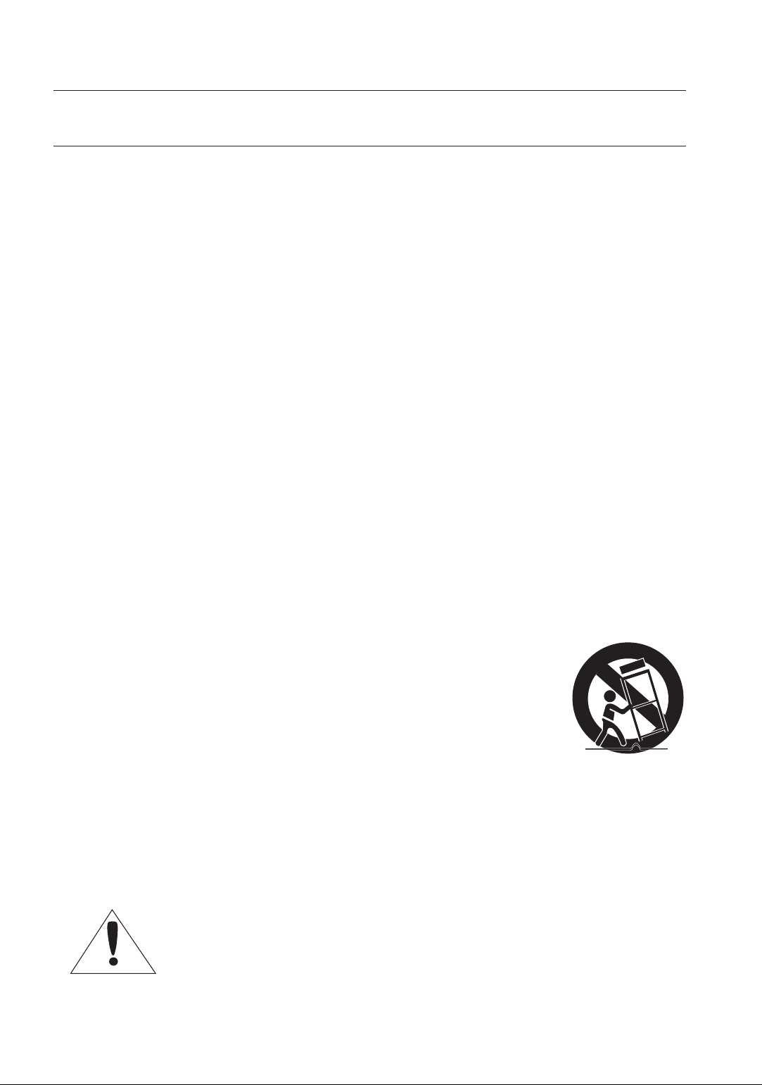
Use only with the cart, stand, tripod, bracket, or table
12.
specifi ed by the manufacturer, or sold with the apparatus.
When a cart is used, use caution when moving the cart/
apparatus combination to avoid injury from tip-over.
Unplug this apparatus during lightning storms or when
13.
unused for long periods of time.
Refer all servicing to qualifi ed service personnel. Servicing is required when
14.
the apparatus has been damaged in any way, such as powersupply cord
or plug is damaged, liquid has been spilled or objects have fallen into the
apparatus, the apparatus has been exposed to rain or moisture, does not
operate normally, or has been dropped.
Apparatus shall not be exposed to dripping or splashing and no objects
filled with liquids, such as vases, shall be placed on the apparatus
4_ overview
Page 5

CONTENTS
OVERVIEW
2
INSTALLATION &
CONNECTION
11
SETUP
14
4 Important Safety Instructions
5 Contents
6 Features
7 What’s Included
7 Part Names and Functions
11 Preparing Installation
11 Connecting the Cables
14 Main Menu
15 Profi le
17 Camera Set
26 Intelligent Video
28 Privacy Zone
29 Preset
30 Other Set
31 Communication
31 System Info
32 Language
English
APPENDIX
33
33 Shortcut Keys
34 Specifi cations
English _5
Page 6

overview
FEATURES
With the state-of-the-art digital signal processing technology, full digital image
processing and special algorithm of 600-line high resolution implemented.
High Sensitivity: It implements images of high sensitivity using the up-to-date SuperHAD IT CCD(SCC-C4237P/C4337P)/ExView-HAD PS CCD(SCC-C4239P/C4339P).
VPS(Virtual Progressive Scan): This is an advanced technology that reproduces a
sharp progressive image. This is appropriate to high quality recording and fi le transfer
via the Internet. (SCC-C4239P/C4339P only)
High performance surveillance camera, equipped with x34 zoom lens and digital
zoom IC, enabling monitoring up to 544 times
WDR extends the contrast range as it takes a picture of each of dark and bright areas
before compositing the two, which is useful if you take a picture of windows inside
a building. Namely, it improves the picture quality of the outdoor scenery as well as
indoor.(SCC-C4239P/C4339P only)
Low Illumination: It uses the digital signal technologies such as low illumination
and Day/Night functions that make your camera identify objects even in the worst
environment.
XDR (eXtended Dynamic Range): Actively controls the gamma compensation in the
way it operates the ambient luminance contrast in a certain pixel unit to determine
the optimal visibility.
Digital Power Synchronization: The full digital Line Lock function directly adjusts the
vertical camera synchronization to enhance the operationability and reliability of this
camera.(SCC-C4337P/C4339P only)
DAY/NIGHT:
illumination below the normal value.
White Balance to control the brightness to the illumination
Superior Backlight Adjustment:When an object has a bright illumination or sunlight
behind it, this camera automatically improves the shaded object picture quality.
Auto Focus to automatically adjust the focus to the subject movement
Privacy zone to hide a specifi c area for personal privacy.
This function can make the IR Cut fi ltering function inactive under the
6_ overview
Page 7
WHAT’S INCLUDED
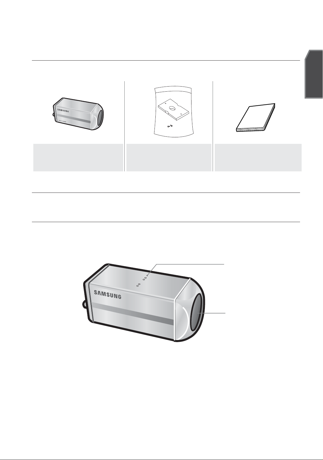
Please check if your camera and accessories are all included in the product package.
Camera Holder
Camera
(Mount Adaptor)
2 Screws
User's Manual
PART NAMES AND FUNCTIONS
English
SIDE VIEW
Wipe out a dirty surface of the lens softly with a lens tissue or cloth to which you have
M
applied ethanol.
Mount Adapter
Fixing Grooves
Camera Lens
English _7
Page 8

overview
Rear Panel
SCC-C4337P
SCC-C4237P
SCC-C4339P
SCC-C4239P
Input/Output Connector
This connector has input and output ports for RS-485 control signals,
DAY/NIGHT switching, and alarm output signals.
SCC-C4239P/C4339P
SCC-C4237P/C4337P
8_ overview
Page 9
1. ALARM OUT
Alarm out jack for motion detection. (Open Collector, On Gnd)
2. GND
Grounding jack.
3. TRIGGER IN (SCC-C4239P/C4339P)
Displays the current still image when it receives the Trigger signal. (Normal
Open Type)
4.5.6 FOCUS, COM, ZOOM
This port is used for ZOOM/FOCUS, MENU CONTROL, HOME
RETURN, and ONEAF by using an external controller.
Depending on the input condition, 4 modes, A, B, C, and D are
available. (SPECIAL - CTRL TYPE)
(Operation Voltage Range : +3V~+13V, -3V~-13V)
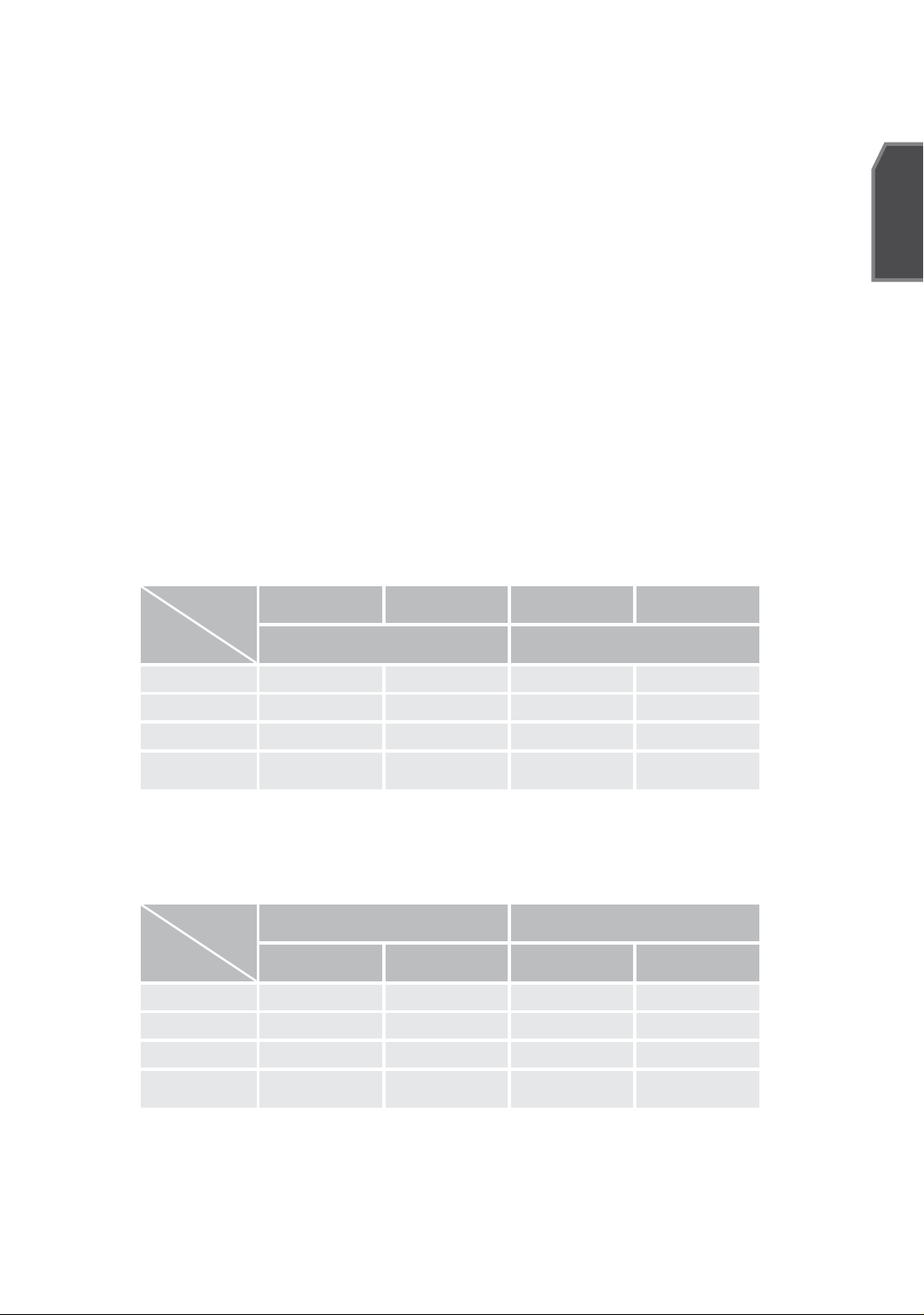
1) When the voltage is supplied to either ZOOM or FOCUS port
English
Function
*1
Code
A -6V +6V -6V +6V
B -6V +6V +6V -6V
C +6V -6V -6V +6V
D
Tele(Up)
ZOOM Port FOCUS Port
+6V -6V +6V -6V
Wide(Down)
Near(Left) Far(Right)
*1: During MENU OFF, controls ZOOM/FOCUS and during MENU ON,
changes the direction, Up/Down/Left/Right SETUP switch.
2) When the voltage is supplied to both ports
Function
Code
A -6V -6V +6V +6V
B -6V +6V +6V -6V
C +6V -6V -6V +6V
D
ENTER/AF *2 HOME RETURN *3
ZOOM Port
+6V +6V -6V -6V
FOCUS Port
ZOOM Port
FOCUS Port
English _9
Page 10

* 2 : For short voltage supply during MENU OFF, executes ONEAF and for
more than 2 second
* 3 : For more than 2 second long voltage supply, moves to the PRESET
0(HOME) position.
7. 5V OUT
Power supply jack for RS-485 JIG. Use within typical DC +5V 100mA.
8. DAY/NIGHT IN
This is a function to receive the external DAY/NIGHT signal from the
sensor(option) and convert the signal into BW.
9. RS-485 DATAJack for connection to RS-485 DATA- signal line.
10. RS-485 DATA+
Jack for connection to RS-485 DATA+ signal line.
SETUP Switch
This switch is used to set the function or property. When this switch is pressed
for at least 2 seconds, the MAIN MENU appears.
ef (Left/Right)
cd
(Up/Down) :
: When you press this switch in the menu, the selected function is confi rmed.
To enter a submenu, press this button.
: By pressing this switch left or right, you can move left or right
on the menu or change the displayed value.
By pressing this switch up or down, you can move up or down on
the menu.
Video OUT Port
This is connected to the Video Input Port of the monitor and it outputs the
Video signals.
GND
This is a grounding port.
Power Connection Port
This is connected to the Power cable.
Power Display LED
When the power is normally connected, the red LED lights.
10_ installation & connection
Page 11
installation & connection
PREPARING INSTALLATION
To install and use the camera, fi rst prepare the following cables.
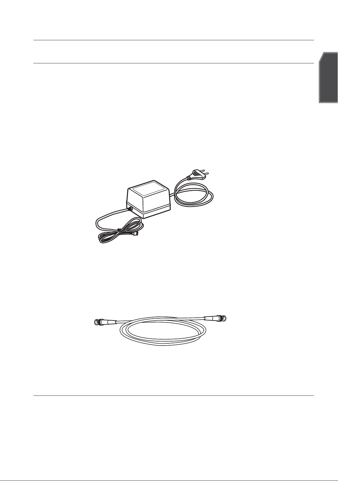
POWER ADAPTER CABLE (SOLD SEPARATELY)
The requirements for the power adapter, which connects to the camera’s
POWER IN terminal, are as follows:
- SCC-C4237P/C4239P : DC 12V 600mA
- SCC-C4337P/C4339P: AC 24V 300mA
DC 12V 600mA
English
VIDEO CABLE(SOLD SEPARATELY)
Use a BNC cable, such as the one shown below, to connect the camera’s VIDEO
OUT to the monitor.
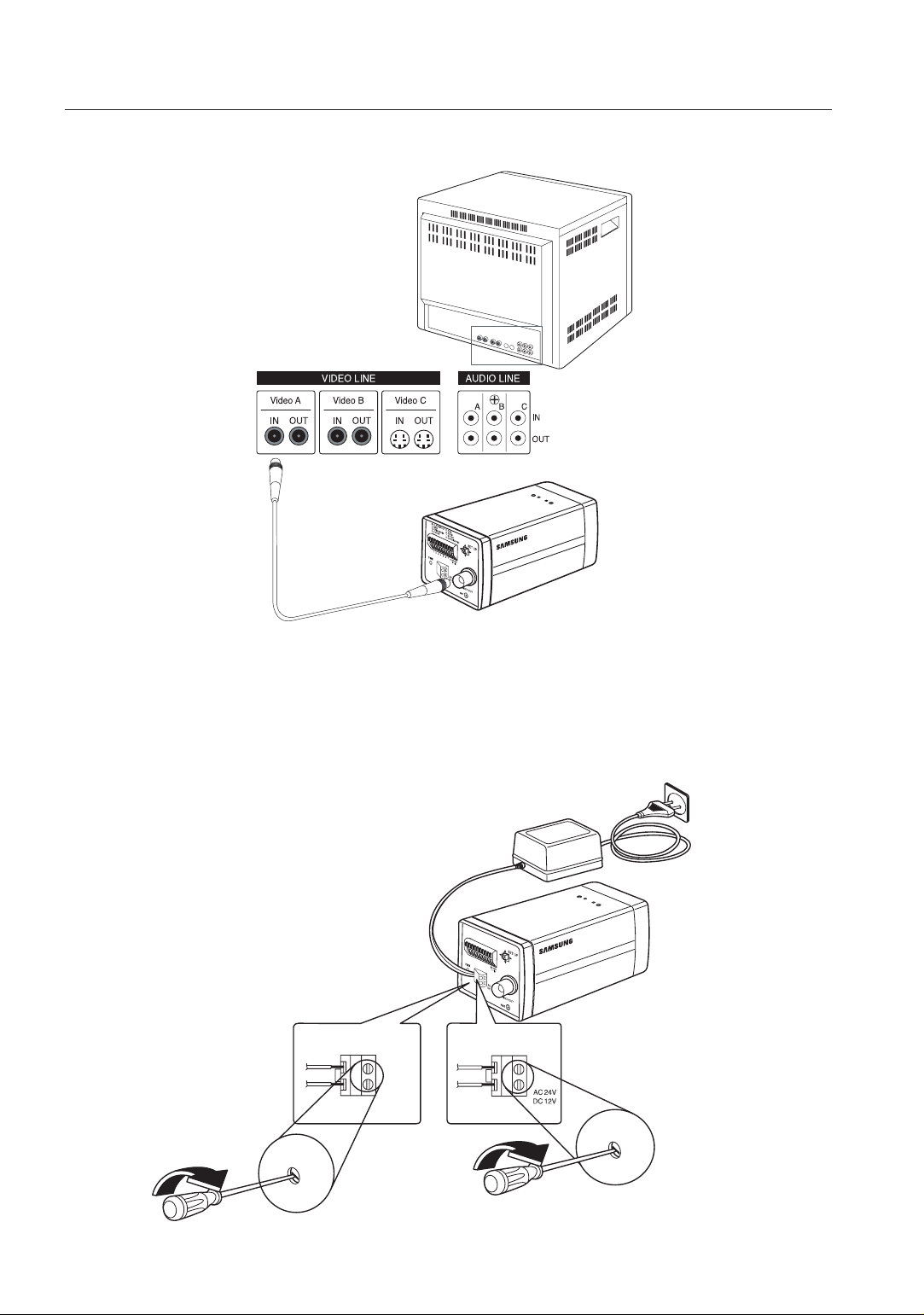
INSTALLATION
1. Connect one end of the BNC cable(not included) to the VIDEO OUT.
2. Connect the other end of the BNC cable (not included) to the VIDEO IN of the
monitor.
English _11
Page 12
installation & connection
Video In Terminal of Monitor Rear Surface
BNC cable(not included)
Video Out Terminal
3. Plug in the power adapter(not inlcluded). Use a “minus” screwdriver to connect one
part of the power adapter, which consists of two lines, to the POWER terminal of the
camera as follows :
1.
ALARAM
2. GND
OUT
3.
TRIGG
5.
COM
4.
FOCUS
ER IN
6.
ZOO
7. 5V O
M
8. D
UT
A
Y/NI
GH
T IN
1
2 3
4 5
6 7
8
+12V
GND
SCC-C4237(P)/C4239(P)
12_ installation & connection
SCC-C4337(P)/C4339(P)
Page 13
4. Determine the type of power supply and set the POWER SELECTION switch
accordingly. Next, plug the power adapter into a wall outlet.
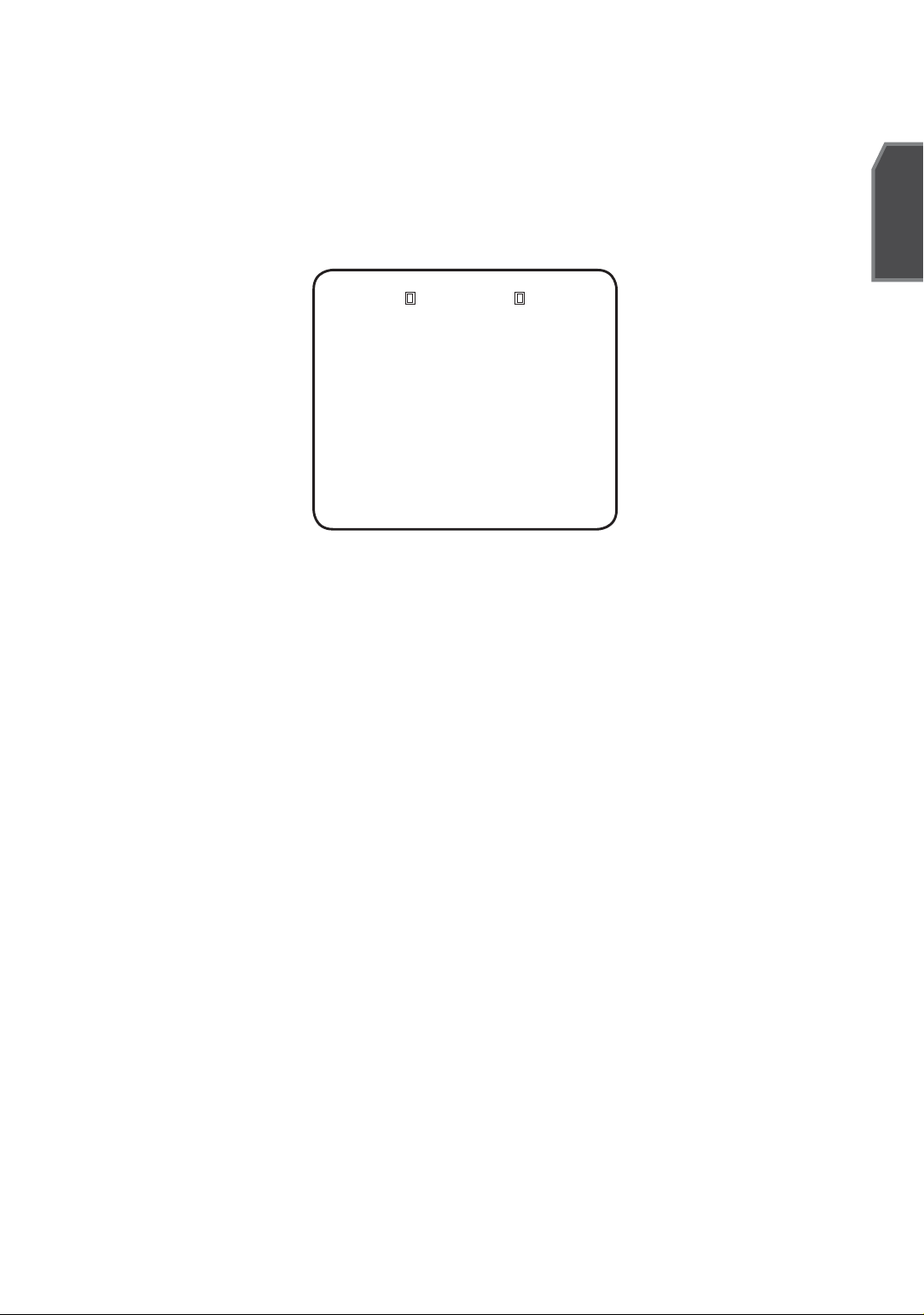
5. If the camera operates normally, the following screen will be displayed for
5 seconds and then disappears.
SYSTEM INFO
TYPE 4_34 ZOM_WDR_PTYPE 4_34 ZOM_WDR_P
PROTOCOL SAMSUNGPROTOCOL SAMSUNG
ADDRESS 0ADDRESS 0
COMM.TYPE RS485,HALFCOMM.TYPE RS485,HALF
BAUD RATE 9600BAUD RATE 9600
CAMERA VER. V1.00_090817CAMERA VER. V1.00_090817
LENS OKLENS OK
6. The requirements for RS485 control is as follows :
- Signaling Speed: 9600 bps
- Data Bit : 8 bits
- Stop Bit : 1 bit
- Parity Bit : none
English
English _13
Page 14
setup
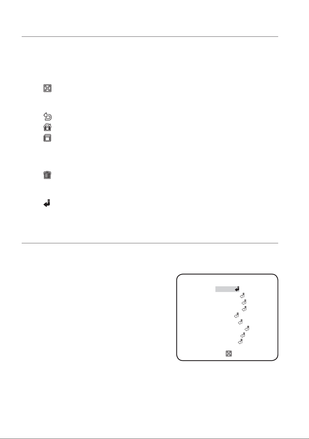
Using OSD icons
:
If these icons appear in the left and right corner of a menu item, you can use
◄►
them move to the previous or next menu.
(EXIT): Exits the menu setup screen.
Before exiting the setup screen, select <SAVE> to save your settings
to the whole menus, or <QUIT> to cancel them.
(RET): Saves your settings and returns to the previous screen.
(HOME): Returns to the main menu.
(SAVE): Use this icon if you want to save your settings after you specifi ed the
mask area and privacy area, etc.
Once you saved your settings, the changes remain intact even if you
select <QUIT> on exit.
(DEL): Use this icon if you want to delete a mask, or privacy area, etc.
Once you deleted your settings, the deletions remain valid even if you
select <QUIT> on exit.
: This icon appears in the right of a menu containing sub menu items.
MAIN MENU
This is the fi rst screen you ever see when you turn on the camera where you can set the
camera environment to your needs.
PROFILE
Select a mode appr--opriate to the camera
installation environment.
CAMERA SET
You can configure the camera settings.
INTELLIGENCE
Offers motion detection and tracking functions.
PRIVACY ZONE
You can configure the privacy settings.
PRESET
You can set the PRESET POSITION.
OTHER SET
You can reset the camera, or adjust the OSD color to your preference.
MAIN MENUMAIN MENU
PROFILE
CAMERA SETCAMERA SET
INTELLIGENCEINTELLIGENCE
PRIVACY ZONEPRIVACY ZONE
PRESETPRESET
OTHER SETOTHER SET
COMMUNICATIONCOMMUNICATION
SYSTEM INFOSYSTEM INFO
LANGUAGELANGUAGE
14_ setup
Page 15
COMMUNICATION
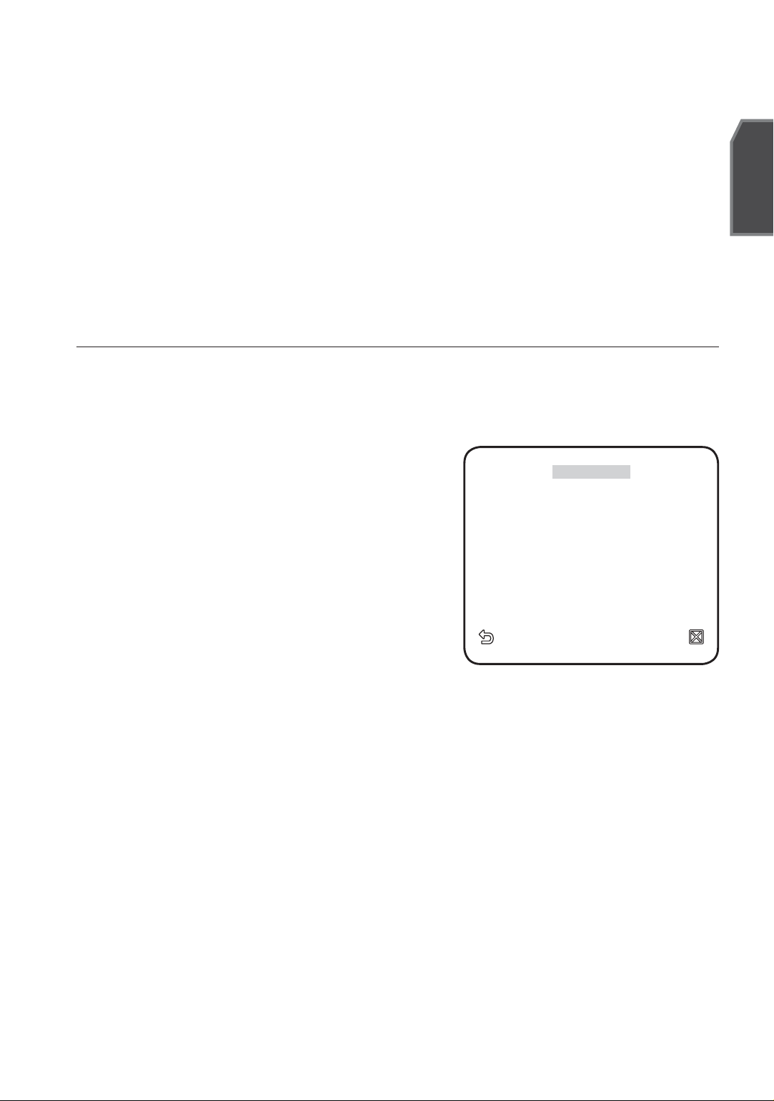
Confi gures the settings pertaining to RS-485 communication.
SYSTEM INFO
Shows the system information such as the camera version or communication
settings.
LANGUAGE
Select a preferred one from the supported languages.
PROFILE
You can select one from the pre-determined confi gurations as appropriate to your
specifi c camera installation environment.
Your selection on each item in PROFILE will affect all other settings of the camera.
STANDARD
English
Automatically optimizes the camera
settings to the normal environment.
ITS
This setting enables you to analyze
the traffi c situation and take the traffi c
information at a glance.
BACKLIGHT
W
PROFILE
STANDARDSTANDARD
ITSITS
BACKLIGHTBACKLIGHT
DAY/NIGHTDAY/NIGHT
GAMINGGAMING
CUSTOMCUSTOM
X
This setting enables you to view a sharp
background and object even in a severe
backlight scene.
DAY/NIGHT
Automatically optimizes the camera settings to the day and night scene.
GAMING
This automatically confi gures the settings so that you can work in a stable
illumination condition as indoors.
CUSTOM
Your change to any of the PROFILE settings will switch the display to CUSTOM.
English _15
Page 16

setup
CAMERA SETUP MENU
Parent Menu Sub-menus
VPS OFF ON OFF OFF OFF
ALC -----
LEVEL 00000
BACKLIGHT OFF OFF WDR OFF OFF
IRIS
MOTION
DNR
SHUTTER
SENSE UP
WDR -----
WEIGHT Custom Setting Custom Setting MEDIUM Custom Setting Custom Setting
WDR LEVEL Custom Setting Custom Setting 0 Custom Setting Custom Setting
WHITE BAL Custom Setting Custom Setting Custom Setting Custom Setting Custom Setting
STANDARD ITS BACKLIGHT DAY/NIGHT GAMING
ALC ALC ALC ALC ALC
(F.FAST)
---
MEDIUM MEDIUM MEDIUM MEDIUM MEDIUM
OFF OFF OFF OFF OFF
AUTO X4 AUTO X2 AUTO X4 AUTO X4 AUTO X4
(F.FAST)
---
NORM
(F.FAST)
---
SLOW
XDR
DAY/NIGHT
WHITE BAL
MEDIUM MEDIUM MEDIUM MEDIUM MEDIUM
AUTO AUTO DAY AUTO DAY
NIGHT -----
BURST OFF ON OFF OFF OFF
EXT -----
BURST -----
DAY DAY/NIGHT DAY DAY/NIGHT DAY
DAY -----
MODE ATW2 ATW1 ATW1 ATW1 ATW1
RED 00000
BLUE 00000
NIGHT ----BRIGHTNESS
MODE OFF ATW2 OFF ATW2 OFF
RED -0-0-
- MEDIUM - MEDIUM -
DETAIL
16_ setup
BLUE -0-0-
22222
Page 17
CAMERA SET
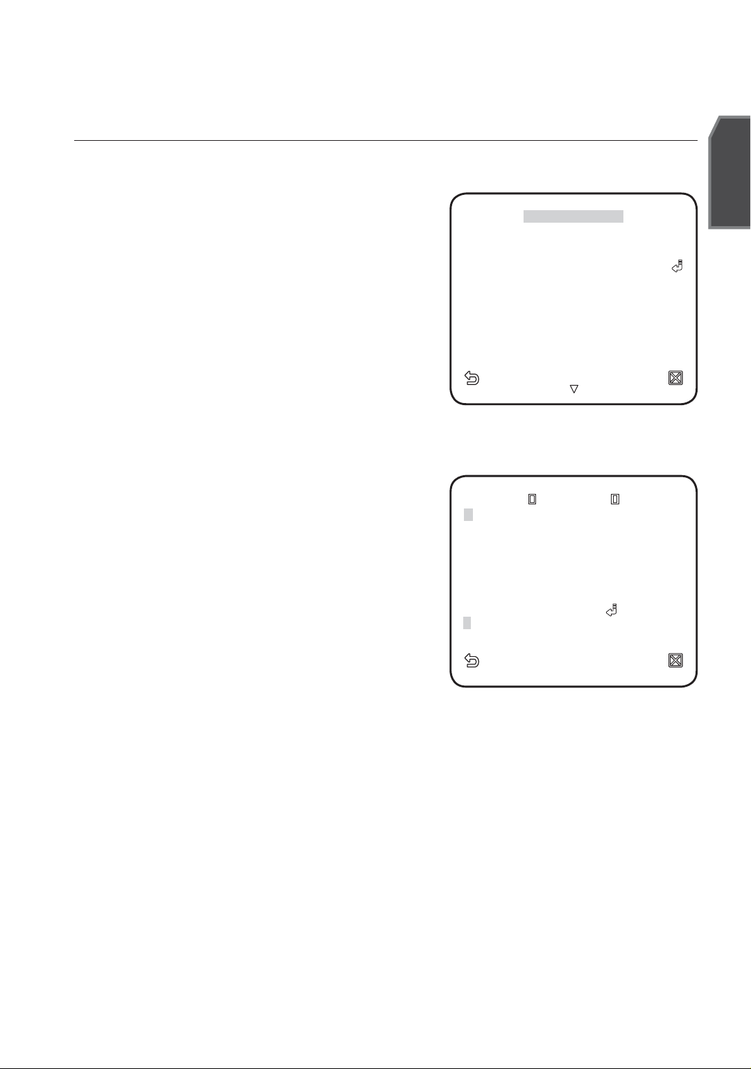
You can confi gure the general settings of the camera module.
1.
Select <MAIN MENU> - <CAMERA SET>.
The Camera Setup menu appears.
2.
Change the settings as necessary, or
select an item to check.
CAMERA ID
CAMERA ID OFFCAMERA ID OFF
VPS OFFVPS OFF
IRIS ALCIRIS ALC
MOTION (F.FAST) MOTION (F.FAST)
DNR MIDDNR MID
SHUTTER (OFF) SHUTTER (OFF)
SENS-UP AUTO X4SENS-UP AUTO X4
FLICKERLESS OFFFLICKERLESS OFF
XDR MIDXDR MID
W
CAMERA SET
English
X
------
------
Provide the ID and location for a camera that
displays on the screen.
Select <CAMERA SET> - <CAMERA ID>.
1.
▲▼
2.
Use
to select a desired character,
◄►
ABCDEFGHIJKLMNOPQRSTUVWXYZOBCDEFGHIJKLMNOPQRSTUVWXYZO
12 345678 9 123456789
CAMERA IDCAMERA ID
__
: ?: ?
++
()/()/
then press [ENTER].
XXXX
WWWW
SPSP
In the lower input box of the screen, the
selected character will be entered.
You can enter up to 54 characters including
-
- - - - - - - - - - - - - - - - - - - - - - - - - - - - - - - -
- - - - - - - - - - - - - - - - - - - - - - - - - - - - - - - - -
SP LOCATIONSP LOCATION
alphabets, numbers and special characters.
LOCATION : Specify the display position of the camera ID.
3.
When done, press [ENTER].
The camera ID will be displayed in the specifi ed position.
VPS
If you set it to <ON>, the camera images will be displayed in progressive mode.
M
VPS is only available for SCC-C4239P and SCC-C4339P.
English _17
Page 18
setup
IRIS
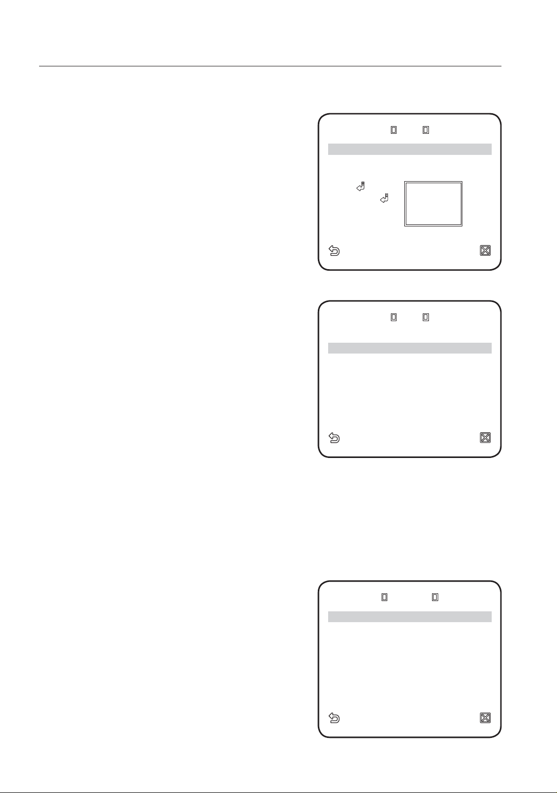
The IRIS menu is useful if you set to adjust the
ALCALC
intensity of radiation incoming to the camera.
[
00]
----I----
ALC : Adjust the open and close of the iris.
- LEVEL : Select an overall brightness level.
- BLC : With <BACKLIGHT> set to
LEVEL
BACKLIGHT BLCBACKLIGHT BLC
AREA USERAREA USER
<SIZE><SIZE>
<LOCATION><LOCATION>
<BLC>, you can specify the BLC area.
With AREA set to <USER>, you can specify the position and size.
- WDR : If you set <BACKLIGHT> to
<WDR>, you will see a menu where you
can set the WDR options.
Specify the shutter speed in WDR LEVEL,
and, the composition level in <WEIGHT>.
Select OUTDOOR, or INDOOR in
LEVEL LEVEL
BACKLIGHT WDR
WEIGHT MIDWEIGHT MID
WDR LEVEL WDR LEVEL
WHITE BAL INDOORWHITE BAL INDOOR
ALCALC
[ [
[ [ 00]]
0000]]
--------II--------
--------II--------
<WHITE BAL>.
The WDR feature provides an extension of
the gain range, which is useful, especially
if you work on pictures both indoors and
outdoors from inside of a building.
Namely, it improves the sharpness of the picture in outdoor scenery as well as
indoor.
M
MANUAL : Adjust the iris level manually.
M
18_ setup
As long as you use the VPS function, the WDR will not be available as the CCD read
method differs accordingly. If you set VPS to ON, WDR will be set to <OFF>
accordingly.
WDR is only available for SCC-C4239P and SCC-C4339P
The overall brightness target of a camera
LEVEL
.
MANUALMANUAL
[ 00]
----I----
will be set to ALC level 0, while the iris can
be adjusted manually.
Page 19
AGC
English
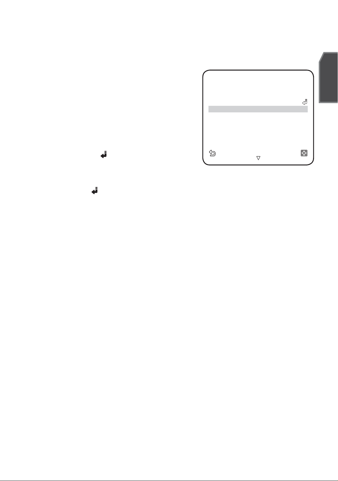
With this, you can adjust the AGC level of a
camera.
With AGC active, if the signal strength falls
below the standard level, AGC will amplify the
video signal to automatically improve the
sensitivity.
If <SENS-UP> is set to <OFF> or <FIX>
mode, the <MOTION> menu will switch to
<AGC>.
With the USER
( )
submenu selected, press
CAMERA ID OFFCAMERA ID OFF
VPS VPS OFFOFF
IRIS ALCIRIS ALC
AGC (VERY HIGH)
DNR MIDDNR MID
SHUTTER SHUTTER OFFOFF
SENS-UP SENS-UP OFFOFF
FLICKERLESS FLICKERLESS OFFOFF
XDR MIDXDR MID
WW
CAMERA SETCAMERA SET
XX
---
[ENTER] to display the corresponding screen.
In this mode, you can select from VERY LOW
to VERY HIGH in 16 levels, enabling deeper, wider choices to your convenience.
()
With the FIX
submenu selected, press [ENTER] to display the corresponding
screen. In this mode, you can select an individualized mode in 16 levels, regardless of
the brightness.
As long as the DAY/NIGHT menu is set to AUTO in Camera Setup, the AGC menu is
M
not available.
As long as FLICKERLESS is set to ON, the AGC mode is not available.
If you set BACKLIGHT to WDR, the AGC fi x mode is not available.
MOTION
You can specify a level of AGC for controlling the camera motion.
This is available only of the SENSE UP menu is set to AUTO.
Select F.FAST if you want to monitor a very fast moving object in a low contrast
scene, and S.SLOW if monitoring a very slow moving, inanimate object in the same
condition.
As long as DAY/NIGHT is set to <AUTO>, the <MOTION> menu is not available.
DNR
Reduces the noise on the camera image.
The higher the level is, the greater the effect is.
Set it to <USER> to specify the level.
English _19
Page 20
setup
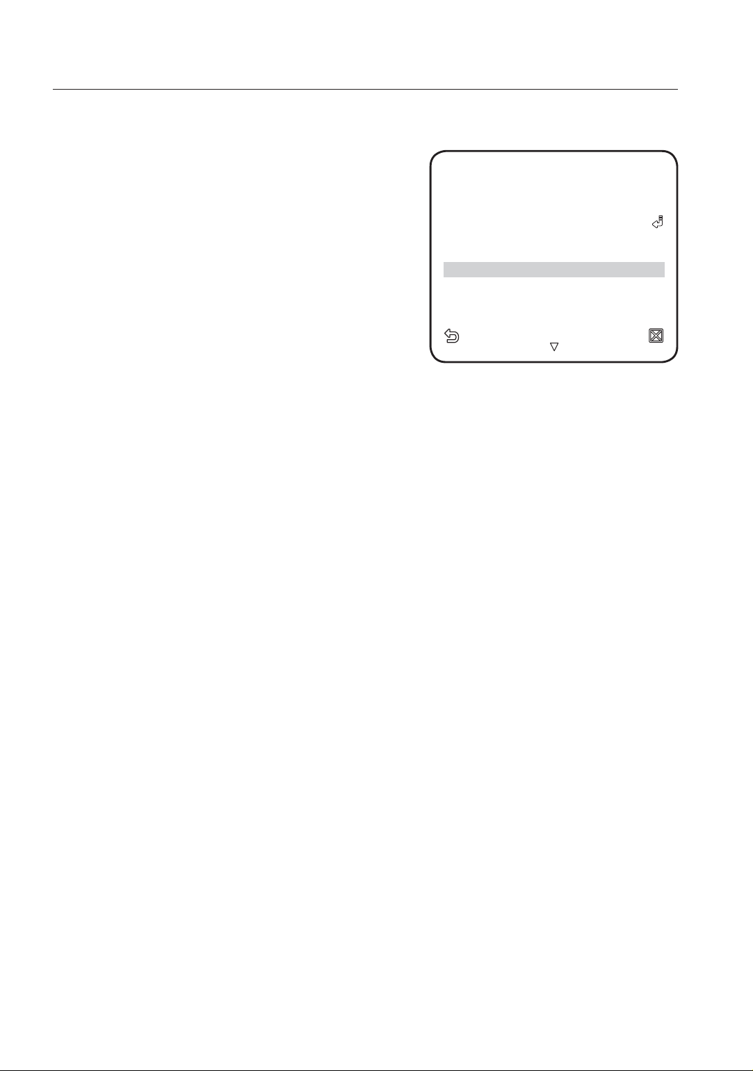
SHUTTER
You can select a fi xed fast electronic shutter
speed in 7 options ranging from 1/120 to 1/10k,
which is mostly used to take a picture of a fast
moving object.
As long as SENSE UP is set to AUTO, FIXED /
FLICKERLESS to ON / BACKLIGHT to WDR, the
SHUTTER menu is not available.
CAMERA ID OFFCAMERA ID OFF
VPS VPS OFFOFF
IRIS ALCIRIS ALC
AGC (VERY HIGH) AGC (VERY HIGH)
DNR MIDDNR MID
SHUTTER 1/120
SENS-UP (SENS-UP (OFFOFF) )
FLICKERLESS (FLICKERLESS (OFFOFF) )
XDR MIDXDR MID
WW
CAMERA SETCAMERA SET
XX
------
------
------
SENS-UP
Automatically senses the darkness level at night or in a low contrast scene, and
extends the accumulation time accordingly; you can select <AUTO> or <FIX> for a
bright and sharp image.
If the SHUTTER menu is set to fi xed electronic shutter mode, the SENSE UP menu will
M
not be available.
If FLICKERLESS is set to ON, or BACKLIGHT to WDR, the FIX mode of the SENSE UP
menu is not available.
FLICKERLESS
This will prevent possible screen distortion due to a mismatch between the vertical
sync frequency and the blinking frequency of the lighting; if set to <ON>, the shutter
speed will be fi xed to 1/120 second.
If SHUTTER is set to FIX, SENSE UP to FIX, and AGC to FIX, the <FLICKERLESS> menu is not
available.
XDR
This will correct a brightness difference between different scenes for the optimal
visibility by calculating the ambient luminance contrast in a certain unit of pixels.
The higher the value is, the higher the correction level is.
20_ setup
Page 21
setup
DAY/NIGHT
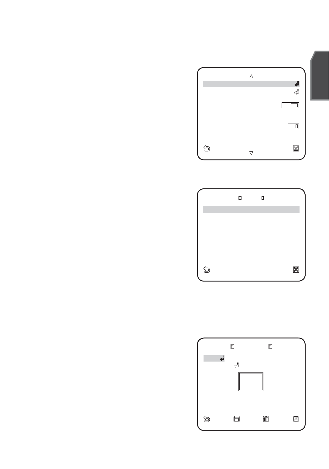
You can specify a recording mode according
to the scene.
1.
Select <CAMERA SET> - <DAY/NIGHT>.
2.
Select a screen transition mode according
to the illumination, and set options as
appropriate.
DAY : Fixed to DAY mode, regardless of
the scene.
NIGHT : Fixed to NIGHT mode,
regardless of the scene.
If BURST is set to <ON>, the burst signal will be output along with the blackand-white composite video signal.
AUTO : According to the luminance, this
will switch DAY to NIGHT mode, or vice
versa.
-
BURST : If set to <OFF>s, the burst signal will not be output in NIGHT mode.
-
DAY¨NIGHT BRIGHTNESS :
Specify the brightness level switching from COLOR to BW fi lter.
Adjusting from HIGH to LOW will cause
to switch the fi lter in a darker screen.
-
DAY¨NIGHT DWELL TIME : Time required to determine the fi lter switch.
-
NIGHT¨DAY BRIGHTNESS : Specify the brightness level switching from
BW to COLOR fi lter. Adjusting from HIGH to LOW will cause to switch the
fi lter in a darker screen.
-
NIGHT¨DAY DWELL TIME : Time required to determine the fi lter switch.
-
MASK AREA : If there exists a bright spot
light source in a night scene, you can
specify the size and position as needed.
This will prevent an error in switching fi lter, or failure to determine the
fi lter switch in a night scene where
a bright spot light source exists.
Any excessively bright area in a night
scene will be MASKed.
Youcan specify MASK 1 and 2 simultaneously.
DAY/NIGHT AUTO
WHITE BAL WHITE BAL
FOCUS MODE ONEAFFOCUS MODE ONEAF
ZOOM SPEED [ZOOM SPEED [22] ]
DISPLAY ZOOM OFFDISPLAY ZOOM OFF
DIGITAL ZOOM OFFDIGITAL ZOOM OFF
DETAIL [DETAIL [22] ]
V-SYNC (INT)---V-SYNC (INT)---
AGC COLOR SUP MIDAGC COLOR SUP MID
AUTO AUTO
BURST OFF
DAYDAY¨¨NIGHT NIGHT
BRIGHTNESS MIDBRIGHTNESS MID
DWELL TIME 2SECDWELL TIME 2SEC
NIGHTNIGHT¨¨DAY DAY
BRIGHTNESS MIDBRIGHTNESS MID
DWELL TIME 5SECDWELL TIME 5SEC
MASK AREA MASK AREA
MASK AREA MASK AREA
<SIZE>
<LOCATION><LOCATION>
English
1 21 2
English _21
Page 22
setup
If <BACKLIGHT> is set to <BLC>, the MASK AREA function is not available.
EXT : The interface to an external alarm enables an automatic switch between
DAY and NIGHT mode.
If you use an infrared light source while in AUTO mode, this may cause a failure in
M
WHITE BAL
If you need to adjust the color according to the ambient illumination, you can use the
<WHITE BAL> function.
AUTO SWITCH or AUTO FOCUS.
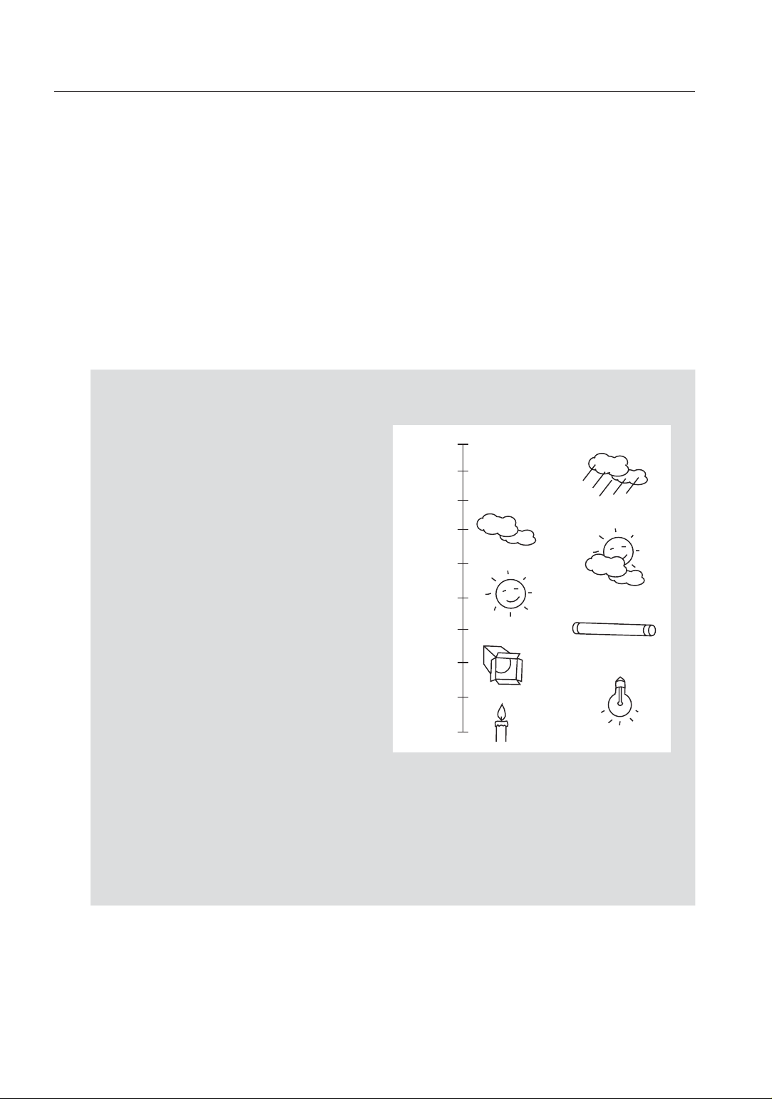
Illumination is generally referred to as color temperature, which is represented in a
measurement of kelvin (K). Color temperatures for ordinary lighting are as follows:
In the <WHITE BAL> menu, you can
set a mode for correcting the <WHITE
BAL>.
- ATW1,2 : If you set the <WHITE
BAL> menu to <ATW1> or
<ATW2> mode, this will monitor
the change of the color temperature
to correct the <WHITE BAL> as
10000K
9000K
8000K
7000K
6000K
5000K
Blue sky
Rainy
Cloudy
Partly Cloudy
needed.
The following color temperature
ranges are assured in individual
4000K
3000K
Sunny
Fluorescent lamp
modes:
ATW1 : 2500K ~ 9300K (1)
2000K
ATW2 : 2000K ~ 10000K
(suitable to sodium light source) (2)
With <ATW1> mode active in a color temperature environment ranging
1 :
1000K
Halogen lamp
Candlelight
Tungsten lamp
beyond between 2500K and 9300K, a proper white balance value may not be
produced; if this is the case, you are recommended to use <ATW2> mode.
2 : With <ATW2> mode active in a mostly single color environment, the display
color and the actual one may differ; so select a mode as appropriate to your
color temperature environment.
22_ setup
Page 23
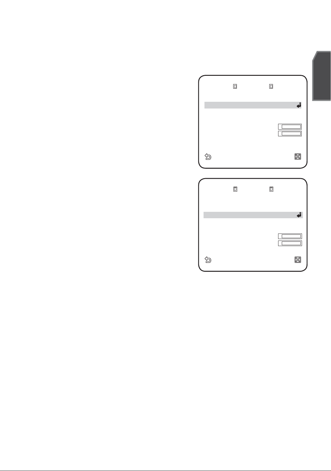
Select <CAMERA SET> - <WHITE BAL>.
1.
Select a mode where you set the <WHITE BAL>.
2.
DAY : You can set the RED, and BLUE
value in DAY mode.
The screen will be displayed in colors
according to your settings.
You can set the R-GAIN, and B-GAIN
value only in <AWC> mode.
NIGHT : You can set the <WHITE BAL> according to the ambient
DAY/NIGHT DAYDAY/NIGHT DAY
MODE AWC
REDRED
BLUEBLUE
R-GAINR-GAIN
B-GAINB-GAIN
WHITE BAL WHITE BAL
[ [
[ [
illumination.
If NIGHT mode is set to <OFF>, the
<WHITE BAL> will operate in a mode
specifi ed in DAY mode at all times;
otherwise, the screen will switch to a
mode specifi ed in <DAY/NIGHT>.
You can set the RED, BLUE and
BRIGHTNESS value in DAY mode.
DAY/NIGHT NIGHTDAY/NIGHT NIGHT
BRIGHTNESS MIDBRIGHTNESS MID
MODE AWC
REDRED
BLUEBLUE
R-GAINR-GAIN
B-GAINB-GAIN
WHITE BAL WHITE BAL
[ [
[ [
The screen will be displayed in colors
according to your settings.
[ [
0000
[ [
0000
00640064
00640064
[ [
0000
[ [
0000
00640064
00640064
English
--------
--------
] ]
] ]
--------
--------
] ]
] ]
I I
I I
I I
I I
--------
--------
--------
--------
] ]
] ]
] ]
] ]
3.
According to the specifi ed recording mode,
select a <WHITE BAL> mode with necessary options.
ATW1,2 : The camera can automatically adjust the color temperature in real
time, according to the ambient conditions.
(Color temperature range 1: 2500K ~ 9300K, 2 : 2000K ~ 10000K)
AWC : Pressing [ENTER] on a desired item will perform ATW once.
You can set the R-GAIN/B-GAIN value.
3200K : Set the color temperature to 3200K.
5600K : Set the color temperature to 5600K.
BRIGHTNESS : Specify a brightness level switching from DAY mode to
NIGHR mode setting.
-
RED : Adjust the strength of the red color.
-
BLUE : Adjust the strength of the blue color.
-
R-GAIN/B-GAIN : Specify the current color temperature manually.
English _23
Page 24
setup
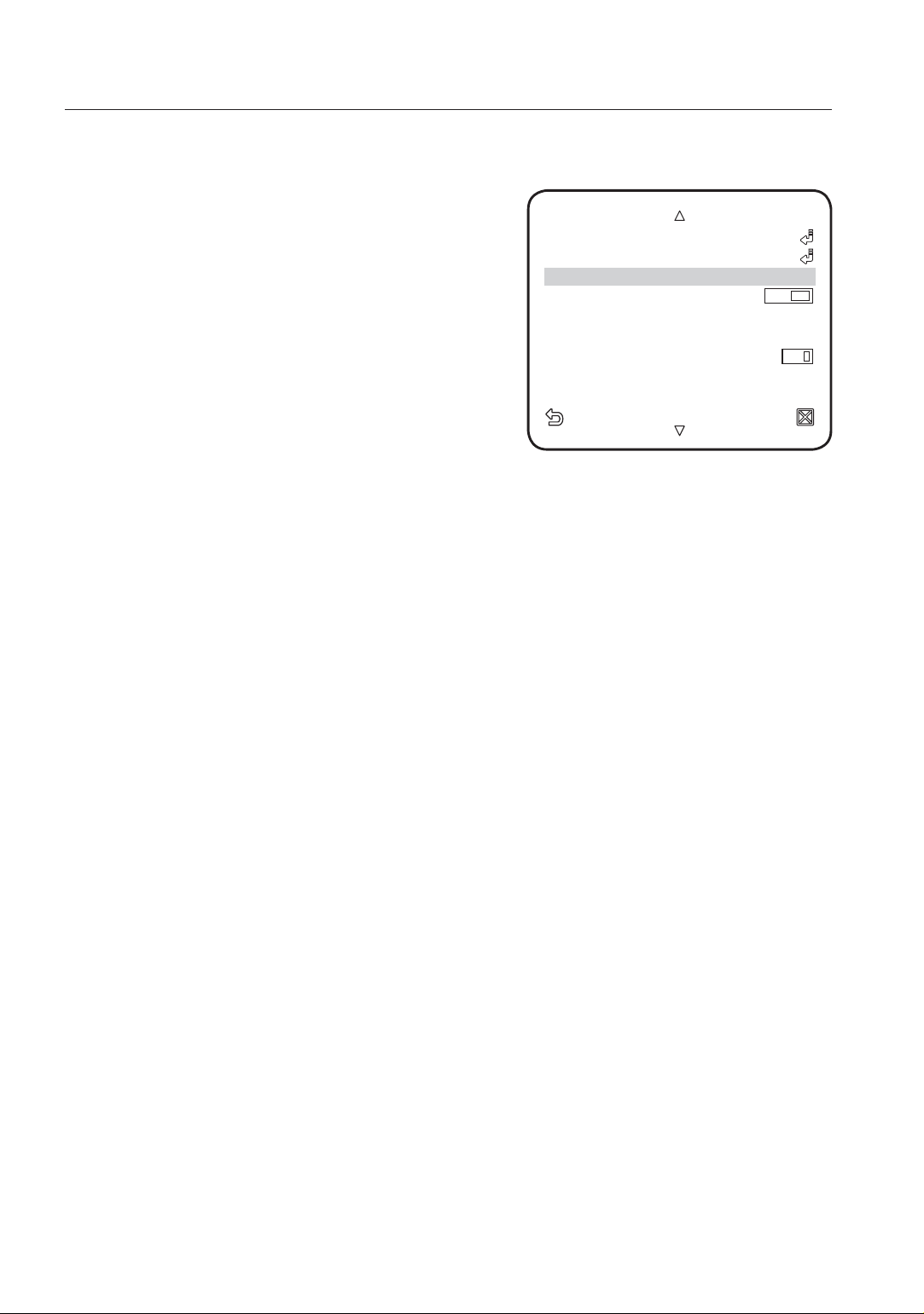
FOCUS MODE
You can select a focus mode according to the
angle that you adjusted for camera recording.
- AF : This will monitor the screen continuously
to focus automatically. If you adjust the focus
manually, that will operate the same as in
<MF>. This will also restore focus after the
operation of zoom.
- ONEAF : Restores focus after the operation
of zoom, and operates the same as in <MF>
unless the operation of zoom is executed.
- MF : You can adjust the focus manually.
While you are working on the following objects, <AF> may not work properly.
M
If this is the case, use <MF> instead.
- Very bright object, or dominant object in a dark scene
- Object against the rear side of a moist or dirty glass
- A scene where nearby and distant objects co-exist
- White wall or single-colored object
- Venetian blinds and other horizontally striped objects
DAY/NIGHT AUTODAY/NIGHT AUTO
WHITE BAL WHITE BAL
FOCUS MODE ONEAF
ZOOM SPEED ZOOM SPEED [2] [2]
DISPLAY ZOOM OFFDISPLAY ZOOM OFF
DIGITAL ZOOM X16DIGITAL ZOOM X16
DETAIL [2] DETAIL [2]
V-SYNC INTV-SYNC INT
AGC COLOR SUP MIDAGC COLOR SUP MID
ZOOM SPEED
You can adjust the zoom operation speed.
DISPLAY ZOOM
You can set to display the zoom status on the screen.
It will disappear in about 3 seconds if the zoom factor has no further change.
DIGITAL ZOOM
You can set the maximum allowable digital zoom ratio.
Digital Zoom will start operation after it is zoomed in to the maximum optical ratio of
x34. If you set DIGITAL ZOOM to x16, you can take a shot at up to x544 (34x16).
When you set DISPLAY ZOOM as on, you may see zoom value on the screen.
DETAIL
Used to adjust the vertical and horizontal distinction, respectively.
24_ setup
Page 25
V-SYNC
You can set the V-SYNC mode.
- If you select <INT>, the camera will use the internal synchronization.
- If selecting <LINE>, the camera will use an external power frequency for
synchronization. The LL-PHASE can be adjusted as appropriate.
It’s a must to use AC 24V power supply when you select line lock for SCC-C4337P
M
and SCC-C4339P.
Line lock is not available for SCC-C4237P and SCC-C4239P.
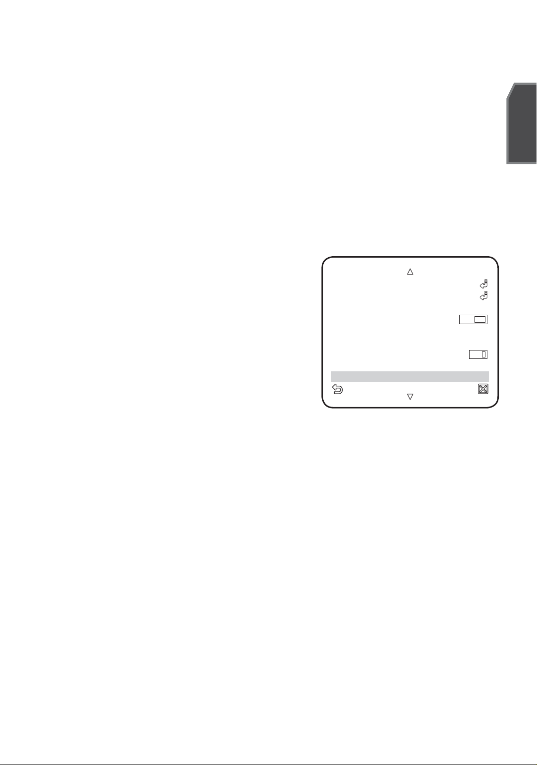
AGC COLOR SUP
English
You can adjust the color reproduction range
according to AGC.
REVERSE
You can reverse the video signal from left
to right, upside down, or vice versa to your
convenience.
DAY/NIGHT AUTODAY/NIGHT AUTO
WHITE BAL WHITE BAL
FOCUS MODE ONEAFFOCUS MODE ONEAF
ZOOM SPEED ZOOM SPEED [2] [2]
DISPLAY ZOOM OFFDISPLAY ZOOM OFF
DIGITAL ZOOM X16DIGITAL ZOOM X16
DETAIL [2] DETAIL [2]
V-SYNC INTV-SYNC INT
AGC COLOR SUP MID
POSI/NEGA
You can set the video brightness signal to normal or reverse.
PIP
You can view a main image with a sub image on the same screen.
If more than one PRIVACY ZONE is specifi ed, and PRIVACY SET to <ON>, the PIP
M
function is not available.
As long as SENSE UP is set to FIXED, PIP menu is not available.
According to the luminance, PIP will disappear if the SENSE UP menu is set to AUTO.
DIS
If you set it to <ON> for a camera that is trembled or vibrated from an ambient
change, this will automatically compensate for the fl icker on the screen.
If you set <DIS> to <ON>, the image will be enlarged with digital zoom as much
M
area as compensated.
English _25
Page 26
setup
If you set the digital zoom to a larger ratio than the actual enlargement for
compensation, the <DIS> function will be disabled.
<DIS> may not work properly in the following images:
Flat, i.e., no regular-patterned image / Low contrast scene / High frequency image
taken under a fl uorescent lamp / Regular-patterned image.
INTELLIGENT VIDEO
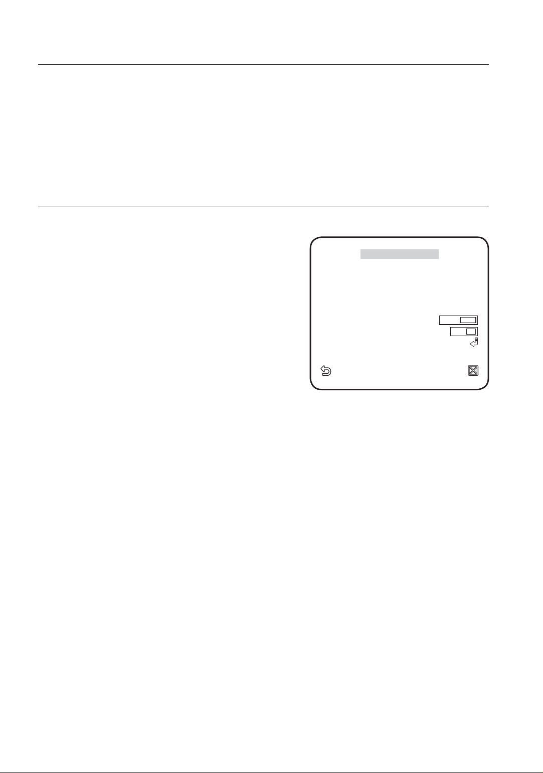
You can enable the motion detection and tracking functions.
Select <MAIN MENU>-<INTELLIGENCE>.
1.
Select each item and set appropriately.
2.
MOTION
You can enable the motion detection and
tracking functions.
MOTION OFFMOTION OFF
ADVANCED OFFADVANCED OFF
MASK AREA MASK AREA
DISPLAY ON DISPLAY ON
SENSITIVITYSENSITIVITY
RESOLUTIONRESOLUTION
ALARM OUT ALARM OUT
W
INTELLIGENCE
[ [
[ [
X
1 2 3 41 2 3 4
] ]
44
]]
33
If you set it to <DETECTION>, the <FIXED/MOVED> option of ADVANCED menu
M
will not be available.
In following situations, motion detection and tracking function may not work
properly.
- When there is sudden changes of brightness
- When the device moves
- When a certain object’s movement fi lls most of the framing area
- When there is diffi culties in distinguishing the moving object and background
ADVANCED
You can detect motions and mark the video that contains such motion, and
enables tracking of the movement.
Selecting the <FIXED/MOVED> option will mark a region if an existing object
disappears, or a new object appears and fi xed for a certain period of time.
In following situations, FIXED/MOVED detection may not work properly.
M
- When multiple motions continue arbitrarily.
- When the object that is fi xed continues to move in the same position.
- When a newly appearing object conceals another object that is moving.
26_ setup
Page 27
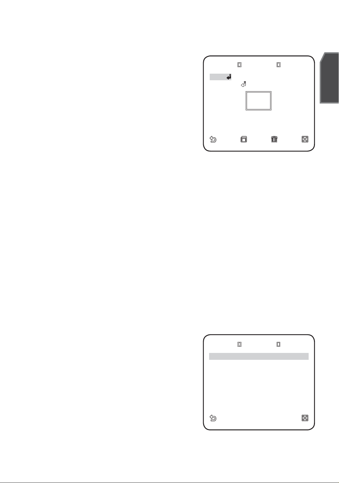
MASK AREA
MASK AREA MASK AREA
Select the number of the area to be
1.
masked that will be excluded from motion
<SIZE>
<LOCATION><LOCATION>
detection.
2.
Select the mask number and set the mask
size and its coverage.
DISPLAY
When selected <ON>, it displays the motion detected and detection of confi gured
advanced function.
SENSITIVITY
English
Sets the sensitivity of motion sensor.
RESOLUTION
The bigger the resolution setting, the smaller the object that can be detected.
ALARM OUT
ALARM OUT ALARM OUT
When selected <ON>, it outputs alarm signal
when the motion is detected and on a detection
of confi gured advanced function.
MOTION ON
FIXED/MOVED ONFIXED/MOVED ON
English _27
Page 28
setup
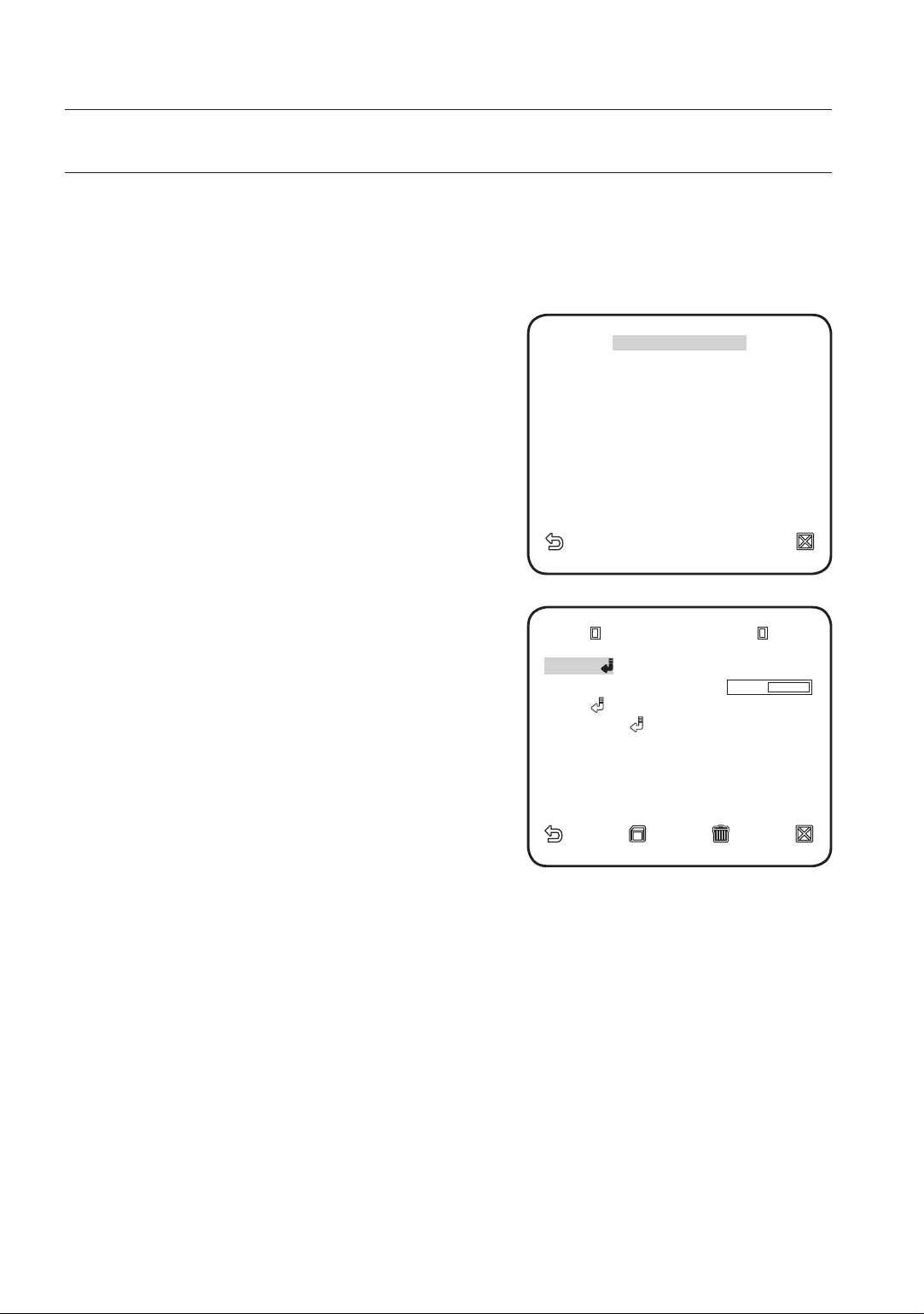
PRIVACY ZONE
You can set up to 12 privacy zones that will be hided for privacy of the subject when
recording.
Zone Setup
1.
Select <MAIN MENU>-<PRIVACY ZONE>.
2.
Select the number of the zone and press
[ENTER].
The Zone setup screen appears.
3.
Select the <ZOOM> and press [ENTER].
▲▼
Using
4.
Select the <PIXEL LEVEL>.
to locate zoom position.
◄►
Select the pixel level for the SIZE and
LOCATION settings.
5.
Select the <SIZE> and press [ENTER].
Using
▲▼
, set the size of the privacy
◄►
zone.
1 2 3 4 5 6 1 2 3 4 5 6
7 8 9 10 11 12 7 8 9 10 11 12
PRIVACY SET PRIVACY SET
STYLE STYLE
W
PRIVACY ZONE
PRIVACY ZONE SET 1 PRIVACY ZONE SET 1
X
MOSAIC1MOSAIC1
ONON
6.
Select the <LOCATION> and press
[ENTER].
Using
▲▼
, set the position of the
◄►
privacy zone.
Save the changes and move to the
7.
previous screen and select the <STYLE>.
Select the <COLOR> and pick a desired
color.
Setting one or more privacy zone and enabling privacy function will disable the PIP
M
function.
For better privacy protection, make your privacy zone bigger than the required, bigger
by about 30%.
Video portion of mosaic pattern or colored by the privacy zone setup is not
recoverable.
<ZOOM>
PIXEL LEVEL [PIXEL LEVEL [44] ]
<SIZE><SIZE>
<LOCATION><LOCATION>
28_ setup
Page 29
PRESET
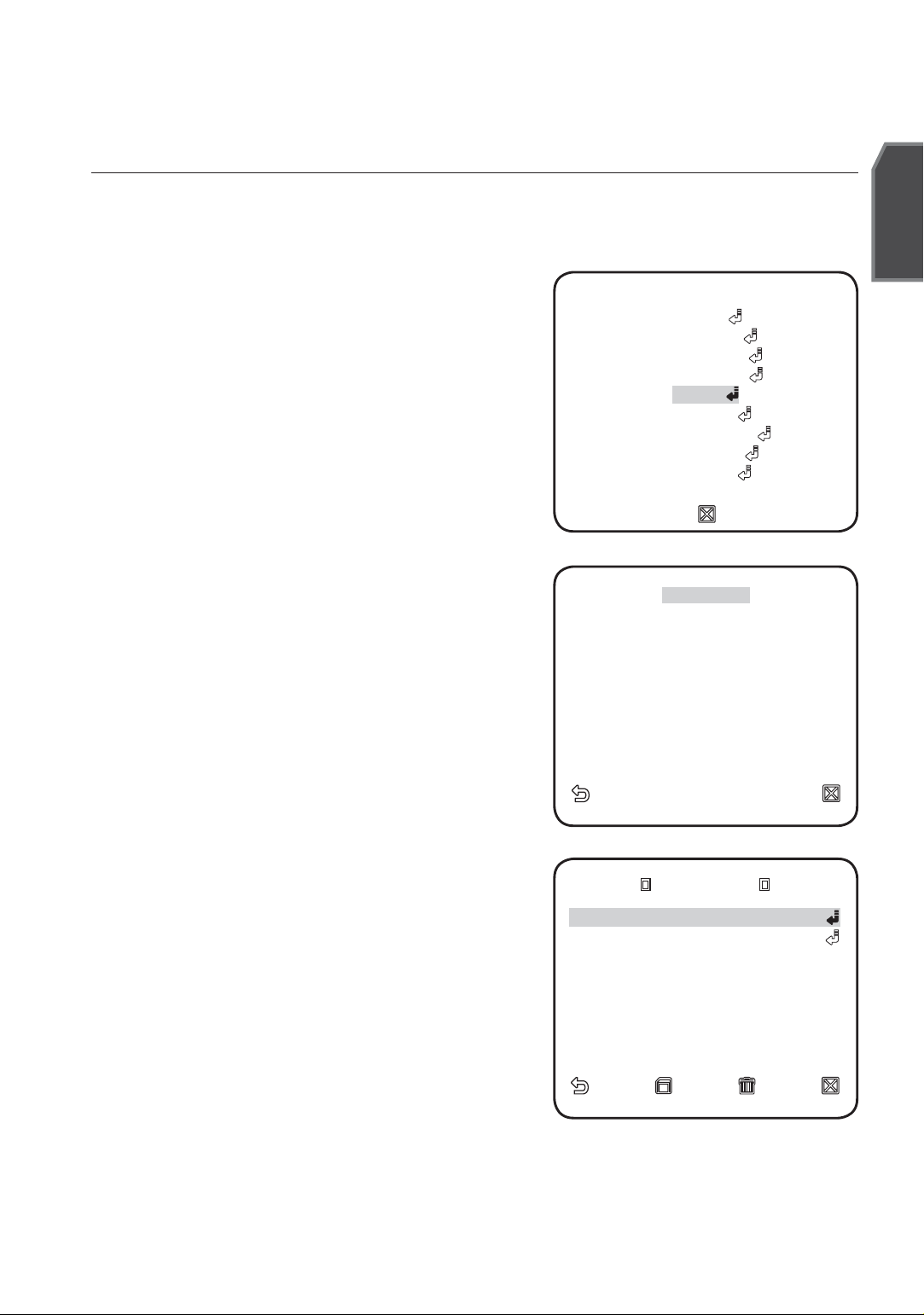
This function provides preset camera settings such as zoom and focus so to enable
quicker and easier accessing and monitoring, which supports up to 512 presets.
1.
Select <MAIN MENU>-<PRESET>.
English
2.
Select the preset number.
3.
Select <POSITION>.
4.
Set <PRESET ID> to <ON> and enter the
name.
For entering the name, refer to “CAMERA ID”.
(page 17)
MAIN MENU MAIN MENU
PROFILEPROFILE
CAMERA SETCAMERA SET
INTELLIGENCEINTELLIGENCE
PRIVACY ZONEPRIVACY ZONE
PRESET
OTHER SETOTHER SET
COMMUNICATIONCOMMUNICATION
SYSTEM INFOSYSTEM INFO
LANGUAGELANGUAGE
W
PRESET
0 0
HH
1 2 3 4 1 2 3 4
5 6 7 8 9 5 6 7 8 9
10 11 12 13 14 10 11 12 13 14
15 16 17 18 19 15 16 17 18 19
20 21 22 23 24 20 21 22 23 24
25 26 27 28 29 25 26 27 28 29
30 31 30 31
1/161/16
WW
HOME RETURN OFFHOME RETURN OFF
X
XX
PRESET NO. 1 PRESET NO. 1
POSITION
PRESET ID ONPRESET ID ON
English _29
Page 30

setup
OTHER SET
You can reset the system by running FACTORY DEFAULTS, or set the font color etc.
Select <MAIN MENU>-<OTHER SET>.
1.
Select each item and set appropriately.
2.
EXTERNAL TRG (OFF)---EXTERNAL TRG (OFF)---
FACTORY DEFAULTS FACTORY DEFAULTS
OSD COLOR BWOSD COLOR BW
CTRL TYPE ACTRL TYPE A
EXTERNAL TRG
Set the EXTERNAL TRG menu to ON and
press the SETUP switch to display the
appropriate screen.
You can set the STILL TIME to 0~4 seconds.
W
OTHER SET
X
If DELAY TIME is set to FIX, the DELAY TIME
will be set in sync with the STILL TIME; if set
to USER, the DELAY TIME will be set to your
setting.
If VPS is set to OFF, the EXTERNAL TRG
M
menu will be deactivated.
FACTORY DEFAULTS
When selected, the <FACTORY DEFAULTS>
screen appears and you can reset all settings to
the factory default settings by selecting the <OK>.
However, the protocol, baud rate, address and the
language settings will not be reset.
Note that the resetting the system to the
M
factory default will erase all settings data.
EXTERNAL TRG EXTERNAL TRG
STILL TIME OFFSTILL TIME OFF
DELAY TIME FIXDELAY TIME FIX
FACTORY DEFAULTS FACTORY DEFAULTS
OK
CANCEL
OSD COLOR
Selects the color of the on-screen display font.
30_ setup
Page 31
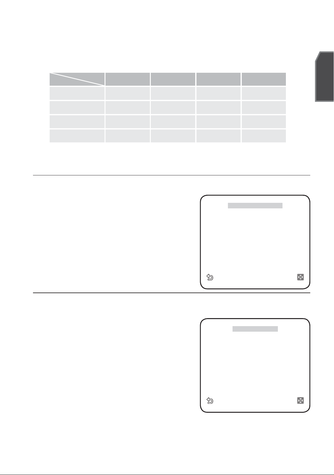
CTRL TYPE
By inputting the wire remote port, you may set up the A, B, C or D mode.
English
Code
Tele
Wide
Far
Near
A -6V +6V +6V -6V
B -6V +6V -6V +6V
C +6V -6V +6V -6V
D +6V -6V -6V +6V
COMMUNICATION
You can set the RS-485 communications setting in regard of the camera.
Select <MAIN MENU>-<COMMUNICATION>.
1.
Select each item and set appropriately.
2.
PROTOCOL, BAUD RATE, ADDRESS :
3.
You can manually set the protocol, baud
rate and address.
RS485RS485
PROTOCOL SAMSUNGPROTOCOL SAMSUNG
BAUD RATE 9600BAUD RATE 9600
ADDRESS 0ADDRESS 0
W
COMMUNICATION
X
SYSTEM INFO
You can check the system information.
Select <MAIN MENU>-<SYSTEM INFO>.
1.
The current system information is
2.
displayed.
W
SYSTEM INFO
TYPE 4_34 ZOM_WDR_PTYPE 4_34 ZOM_WDR_P
PROTOCOL SAMSUNGPROTOCOL SAMSUNG
ADDRESS 0ADDRESS 0
COMM. TYPE RS485, HALF COMM. TYPE RS485, HALF
BAUD RATE 9600BAUD RATE 9600
SERIAL NO. 000000000000000SERIAL NO. 000000000000000
CAMERA VER. v1.00CAMERA VER. v1.00__0000000000
X
English _31
Page 32
setup
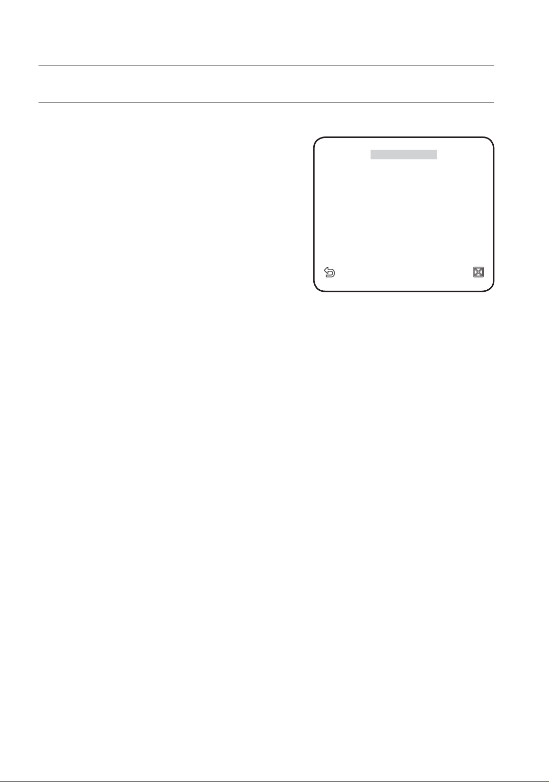
LANGUAGE
You can set the language of the user interface.
1.
Select <MAIN MENU>-<LANGUAGE>.
2.
Select your language using the up/down
keys.
W
LANGUAGE
ENGLISHENGLISH
PУCCKNЙPУCCKNЙ
POLSKIPOLSKI
ČESKYČESKY
TÜRKÇETÜRKÇE
X
32_ setup
Page 33
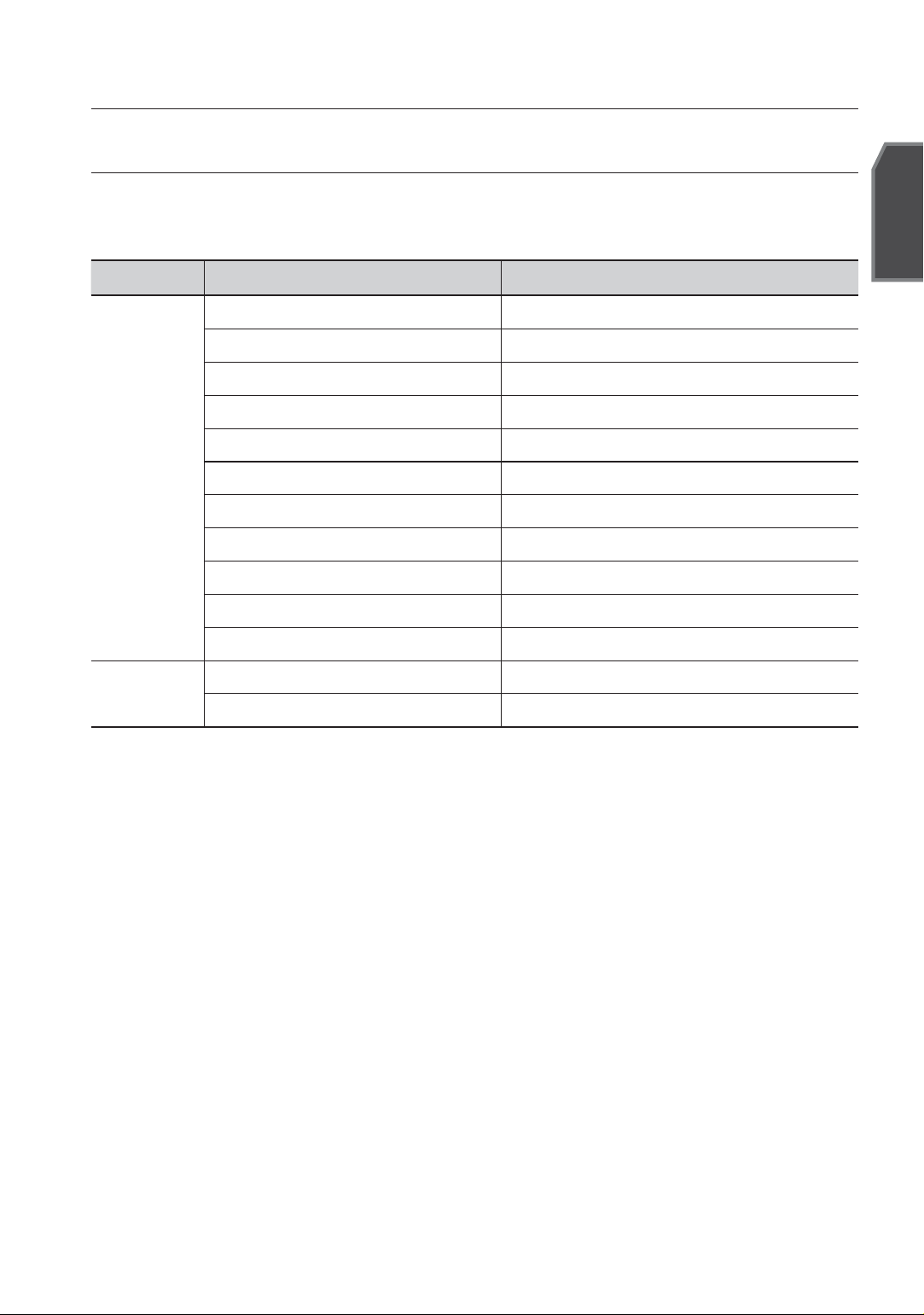
appendix
SHORTCUT KEYS
You may control this camera by using Controller (SSC-5000).
Function Key
DAY/NIGHT - DAY [PRESET] + [5] + [1] + [2] + [ENTER]
DAY/NIGHT - NIGHT [PRESET] + [5] + [1] + [3] + [ENTER]
DAY/NIGHT - AUTO [PRESET] + [5] + [1] + [4] + [ENTER]
DAY/NIGHT - EXT [PRESET] + [5] + [1] + [5] + [ENTER]
IRIS – ALC – BACKLIGHT – WDR [PRESET] + [5] + [1] + [6] + [ENTER]
CAMERA SET
IRIS – ALC – BACKLIGHT – OFF [PRESET] + [5] + [1] + [7] + [ENTER]
IRIS - ALC [PRESET] + [5] + [1] + [8] + [ENTER]
IRIS - MANU [PRESET] + [5] + [1] + [9] + [ENTER]
FOCUS MODE – AF [PRESET] + [5] + [2] + [0] + [ENTER]
FOCUS MODE – MF [PRESET] + [5] + [2] + [1] + [ENTER]
FOCUS MODE – ONEAF [PRESET] + [5] + [2] + [2] + [ENTER]
English
Function
Resetting (Factory Defaults) [PRESET] + [5] + [2] + [3] + [ENTER]
CCD Defect Correction [PRESET] + [5] + [2] + [4] + [ENTER]
English _33
Page 34
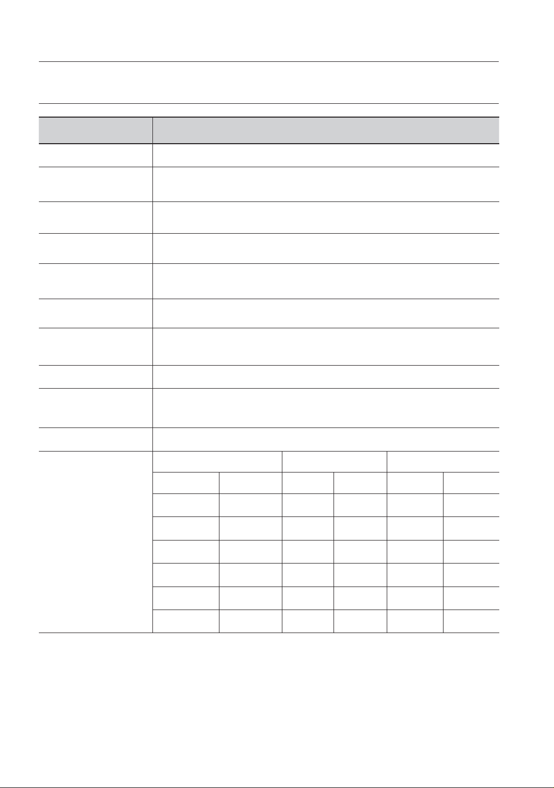
appendix
SPECIFICATIONS
Item Description
Product Type
Power Source
Power Consumption
TV Standard
Image Sensor
Effective Pixels
TV line frequency
Synchronization
Resolution
S/N Ratio
Power Zoom Camera
SCC-C4237P/SCC-C4239P: DC12V
SCC-C4337P/C4339P : AC 24V(50Hz), DC 12V
SCC-C4237P, SCC-C4239P: 4.2W
SCC-C4337P, SCC-C4339P: 5.6W
PAL STANDARD COLOR SYSTEM
SCC-C4239P/C4339P: ExView-HAD PS CCD
SCC-C4237P/C4337P: Super-HAD IT CCD
752(H) × 582(V)
Horizontal : 15, 625 Hz (INT) / 15, 625 Hz (L/L)
Vertical : 50 Hz (INT) / 50 Hz (L/L)
INT/LINE LOCK (LINE LOCK is not available for SCC-C4237P/C4239P)
Horizontal : 600 TV LINES (color)
Vertical : 350 TV LINES
Approximately 52 dB
Minimum subject
illumination
34_ appendix
condition
SENS-UP Illumination Color B/W Color B/W
Off 50IRE 2 0.2 1.2 0.12
Off 30IRE 1.2 0.12 0.7 0.07
Off 15IRE 0.6 0.06 0.3 0.03
x512 50IRE 0.004 0.0004 0.002 0.0002
x512 30IRE 0.002 0.0002 0.001 0.0001
x512 15IRE 0.001 0.0001 0.0007 0.00007
SCC-C4237P/C4337P SCC-C4239P/C4339P
Page 35
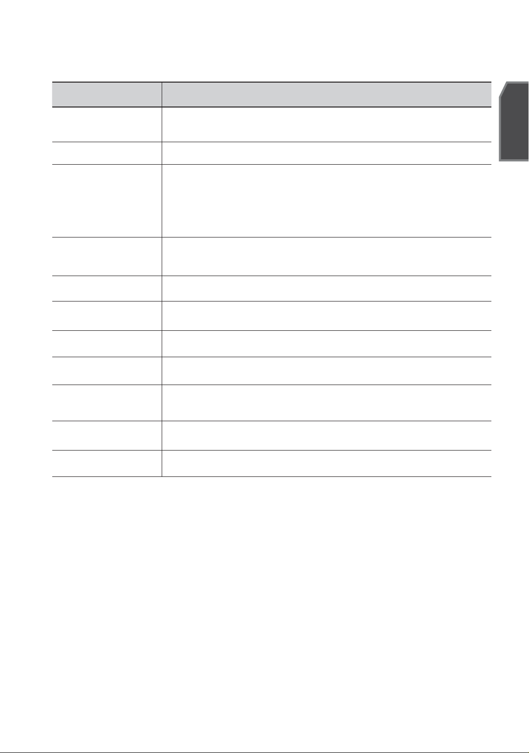
Item Description
English
WDR
Signal Output
Lens
Electronic shutter
speed
DIGITAL ZOOM 2x ~ 16x
White Balance
Operation Temperature
Operation Humidity
Dimensions
(WxHxD)
SCC-C4239P/C4339P: x160
WDR is not available for SCC-C4237P/C4337P.
COMPOSITE VIDEO OUT : 1.0 Vp-p 75 ohms/BNC
x34 Zoom Lens Integrated
Focal length : 3.4 ~ 115.6mm
Aperture : F1.65(Wide) F3.7(Tale)
- MOD(Minimum Object Distance) : 1000mm
High Speed: OFF~1/10K sec
Low Speed: OFF~X512
ATW1/ATW2/AWC/MANUAL Mode
(3200°K, 5600°K, R/B Gain adjustment)
-10°C~+50°C
~90%
SCC-C4237P/C4239P : 59mm x 59.2mm x 124.2mm
SCC-C4337P/C4339P : 59mm x 59.2mm x 154.5mm
Weight
Product Color
SCC-C4237P/C4239P: 421g, SCC-C4337P/C4339P: 564g
silver
English _35
Page 36
Correct Disposal of This Product
(Applicable in the European Union and other European countries with separate collection systems)
This marking on the product, accessories or literature indicates that the product and its electronic accessories (e.g.
charger, headset, USB cable) should not be disposed of with other household waste at the end of their working
life. To prevent possible harm to the environment or human health from uncontrolled waste disposal, please
separate these items from other types of waste and recycle them responsibly to promote the sustainable reuse
of material resources.
Household users should contact either the retailer where they purchased this product, or their local government
offi ce, for details of where and how they can take these items for environmentally safe recycling.
Business users should contact their supplier and check the terms and conditions of the purchase contract. This
product and its electronic accessories should not be mixed with other commercial wastes for disposal.
(Waste Electrical & Electronic Equipment)
 Loading...