

SCC-B5397
SCC-B5399
DIGITAL COLOR DOME
CAMERA
user manual
ENG FRE
ENG
GER
SPA
imagine the possibilities
Thank you for purchasing this Samsung product.
To receive more complete service,
please register your product at
www.samsungsecurity.com
ITA
Safety information
CAUTION
RISK OF ELECTRIC SHOCK.
DO NOT OPEN
CAUTION: TO REDUCE THE RISK OF ELECTRIC SHOCK, DO NOT REMOVE COVER (OR BACK) NO USER SERVICEABLE PARTS
INSIDE. REFER SERVICING TO QUALIFIED SERVICE PERSONNEL.
This symbol indicates that dangerous voltage consisting a risk of electric shock is
present within this unit.
This exclamation point symbol is intended to alert the user to the presence of important
operating and maintenance (servicing) instructions in the literature accompanying the
appliance.
WARNING
To prevent damage which may result in fi re or electric shock hazard, do not expose this appliance to rain
•
or moisture.
WARNING
Be sure to use only the standard adapter that is specifi ed in the specifi cation sheet. Using any other adapter
1.
could cause fi re, electrical shock, or damage to the product
Incorrectly connecting the power supply or replacing battery may cause explosion, fi re, electric shock, or
2.
damage to the product.
Do not connect multiple cameras to a single adapter. Exceeding the capacity may cause abnormal heat
3.
generation or fi re.
Securely plug the power cord into the power receptacle. Insecure connection may cause fi re.
4.
5.
When installing the camera, fasten it securely and fi rmly. A falling camera may cause personal injury.
6.
Do not place conductive objects (e.g. screwdrivers, coins, metal things, etc.) or containers fi lled with water
on top of the camera. Doing so may cause personal injury due to fi re, electric shock, or falling objects.
7.
Do not install the unit in humid, dusty, or sooty locations. Doing so may cause fi re or electric shock.
2 – DIGITAL COLOR DOME CAMERA

Safety information
1.
If any unusual smells or smoke come from the unit, stop using the product. In such case, immediately
disconnect the power source and contact the service center. Continued use in such a condition may cause
fi re or electric shock.
2.
If this product fails to operate normally, contact the nearest service center. Never disassemble or modify
this product in any way. (SAMSUNG is not liable for problems caused by unauthorized modifi cations or
attempted repair.)
3.
When cleaning, do not spray water directly onto parts of the product. Doing so may cause fi re or electric shock.
CAUTION
1.
Do not drop objects on the product or apply strong shock to it. Keep away from a location subject to
excessive vibrationor magnetic interference.
2.
Do not install in a location subject to high temperature (over 50°C), low temperature (below -10°C), or high
humidity. Doing so may cause fi re or electric shock.
3.
If you want to relocate the already installed product, be sure to turn off the power and then move or reinstall
it.
4.
Remove the power plug from the outlet when then there is a lightning. Neglecting to do so may cause fi re or
damage to the product.
5.
Keep out of direct sunlight and heat radiation sources. It may cause fi re.
6.
Install it in a place with good ventilation.
7.
Avoid aiming the camera directly towards extremely bright objects such as sun, as this may damage the
CCD image sensor.
8.
Apparatus shall not be exposed to dripping or splashing and no objects fi lled with liquids, such as vases,
shall be placed on the apparatus.
9.
The Mains plug is used as a disconnect device and shall stay readily operable at any time.
English – 3
ENG
Safety information
WARNING
Read these instructions.
1.
Keep these instructions.
2.
Heed all warnings.
3.
Follow all instructions.
4.
Do not use this apparatus near water.
5.
Clean only with dry cloth.
6.
Do not block any ventilation openings. Install in accordance with the manufacturer’s instructions.
7.
Do not install near any heat sources such as radiators, heat registers, or other apparatus (including
8.
amplifi ers) that produce heat.
Do not defeat the safety purpose of the polarized or grounding-type plug. A polarized plug has two blades
9.
with one wider than the other. A grounding type plug has two blades and a third grounding prong. The wide
blade or the third prong is provided for your safety. If the provided plug does not fi t into your outlet, consult
an electrician for replacement of the obsolete outlet.
Protect the power cord from being walked on or pinched particularly at plugs, convenience receptacles, and
10.
the point where they exit from the apparatus.
Only use attachments/accessories specifi ed by the manufacturer.
11.
Use only with cart, stand, tripod, bracket, or table specifi ed by the manufacturer, or
12.
sold with the apparatus.
Unplug this apparatus when a card is used. Use caution when moving the cart/
13.
apparatus combination to avoid injury from tip-over.
Refer all servicing to qualifi ed service personnel. Servicing is required when the apparatus has been
14.
damaged in any way, such as powersupply cord or plug is damaged, liquid has been spilled or objects have
fallen into the apparatus, the apparatus has been exposed to rain or moisture, does not operate normally, or
has been dropped.
4 – DIGITAL COLOR DOME CAMERA

Contents
Introduction
Features 6
Product & Accessories 7
Part Names and Functions 8
Installation
Before installation 11
Installation procedure 11
Adjusting the camera direction 13
How to use OSD Menu
Using Icons in the Menu 14
Main Menu 14
Profi le 15
Camera Setup 17
Intelligence 25
Privacy Zone Setup
Other Set 28
System Information 29
Language 29
Specifi cations
Specifi cations 31
27
English – 5
ENG

Introduction
FEATURES
High Resolution
❖
This camera has realized high resolution of 600 lines using the top-notch full digital image processing and special algorithm
•
technologies.
VPS(Virtual Progressive Scan)
❖
This is an advanced technology that reproduces a sharp progressive image. This is appropriate to high quality recording and fi le
•
transfer via the Internet.
Intelligent Motion Detection & Tracking
❖
This is an intelligent function that automatically detects a motion of an object. You can set a virtual fence so it displays an alert if an object
•
passes / enters /exits the virtual fence or virtual area.
WDR
❖
•
WDR extends the contrast range as it takes a picture of each of dark and bright areas before compositing the two, which is useful if
you take a picture of windows inside a building. Namely, it improves the picture quality of the outdoor scenery as well as indoor.
❖
XDR (eXtended Dynamic Range)
•
Actively controls the gamma compensation in the way it operates the ambient luminance contrast in a certain pixel unit to determine
the optimal visibility.
❖
DAY/NIGHT
•
This function can make the IR Cut fi ltering function inactive under the illumination below the normal value.
❖
High Sensitivity
•
It implements images of high sensitivity using the up-to-date SONY Super-HAD Progressive CCD.
❖
Low Illumination
•
It uses the digital signal technologies such as low illumination and Day/Night functions that make your camera identify objects even in the
worst environment.
❖
Superior Backlight Adjustment
•
When an object has a bright illumination or sunlight behind it, this camera automatically improves the shaded object picture quality.
❖
Digital Power Synchronization
•
The full digital Line Lock function directly adjusts the vertical camera synchronization to enhance the operationability and reliability of
this camera.
❖
Output Signal Setting
•
You can set the following Video output signals: Image reversion (Horizontal, Vertical, or both), Privacy, Horizontal/Vertical profi ling,
and digital zooming.
❖
OSD(On Screen Display) Menu
•
OSD menu is provided to display the status of camera and to confi gure the functions interactively.
❖
Coaxial Cable Communication
•
This is a remote control function that overlaps the coaxial cable (for a transfer of the video signal) with the control signal. In installation or repair, this
helps you control the communication controller (optional) without additional cabling.
6 – DIGITAL COLOR DOME CAMERA
Introduction
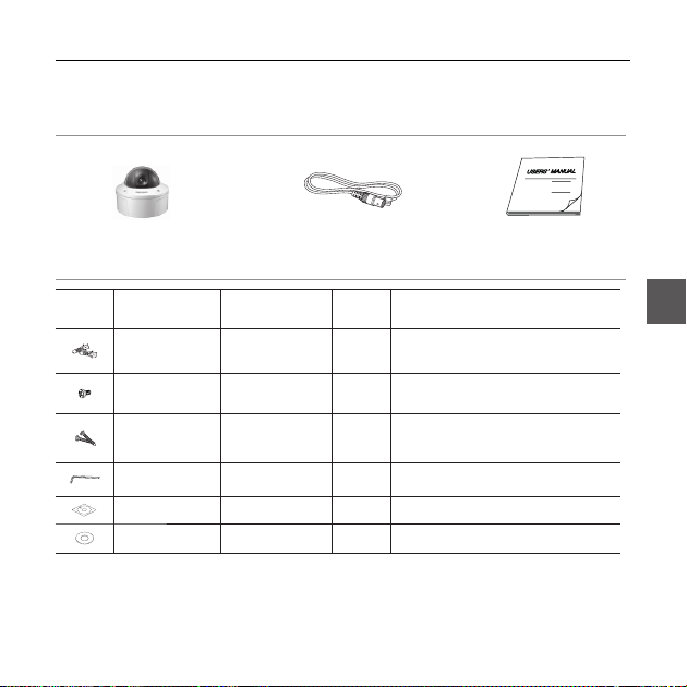
Components
Checking components in the package
Camera
Image Part name Standard Quantity Usage
Plastic anchor HUD 5 4 (EA)
ASSY screw
machine
ASSY screw
tapping
L-Wrench TROX T-20 1
Template 1 Used for guiding the installation
Gasket-pipe hole T2.5 W56 1
NOTE
–
The test monitor cable is used to test the camera by connecting to a portable display. If you
–
really want to connect the camera to a monitoring display, use the BNC cable.
Test Monitor Cable User’s Guide
Attach each piece to screw connection holes for
BH M5 X L6.
(White+o-ring)
TH M4xL30 (Black+
o-ring)
Used for fi lling in the holes when installing
8
Used when installing your camera on the
4
Used for assembling/disassembling the
Used to make a wiring hole when installing
the camera on the ceiling or wall
strengthening connection
pipe and wall mount
ceiling or wall
。
Dome cover
。
ENG
English – 7
Introduction
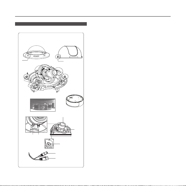
Components of your camera
Your camera has the following components:
1
2
6
12
5
7
910
8 – DIGITAL COLOR DOME CAMERA
3
4
7
6
8
Lens
11
Video connector
Power connector
Dome cover: Covers the inner cover, lens, and
1.
main body to protect them.
Cover screw: Use it to assemble or
2.
disassemble both dome cover and case.
Inner cover: Covers the main body to protect it.
3.
.Wing locker: Push a long thin screwdriver into
4
its narrow spot and press it outward when you want
to remove the inner cover.
Main body: Includes a lens, a switch board, a
5.
PCB board, screws, and such.
Screws for assembly and disassembly: Using
6.
these 2 screws, the Main
body is closely connected to the Case.
Hooker: By pulling the left/right levers in the
7.
arrow direction, the Main body can be detached
from the Case.
Case: Used as a ceiling or wall fi xture. It is
8.
fi xed using four screws provided in the package.
Zoom lever: Using this lever, the lens zoom can
9.
be adjusted and fi xed.
Focus lever: Using this lever, the lens focus can
10.
be adjusted and fi xed.
Tilt fi xing screw: Using this screw, the slope of
11.
the lens can be adjusted and fi xed.
Cable: Connect the Video connector to BNC
12.
cable and Power connector to power adapter.
Introduction
Setting switches❖
SETUP Switch
•
This switch is used to set the function or property. When this switch is pressed for at least 2 seconds, the
MAIN MENU appears.
ef
(Left/Right)
: By pressing this switch left or right, you can move left or right on the menu or change the
cd
(Up/Down) :
: When you press this switch in the menu, the selected function is confi rmed. To enter a submenu, press
this button.
displayed value.
By pressing this switch up or down, you can move up or down on the menu.
English – 9
ENG

Installation
Installing camera
Before installation
Before installing your camera, you have to read the following cautions:
You have to check whether the location (ceiling or wall) can bear fi ve times the weight of your camera.
Don’t let the cable to be caught in improper place or the electric line cover to be damaged. Otherwise it may
cause a breakdown or fi re. You can use wall mount adaptor (SADT-102WM), and pole mount adaptor (SADT-
100PM) for installing the camera on the wall or pipeline.
When installing your camera, don’t allow any person to approach the installation site. If you have any valuable
things under the place, move th
About the installation holes
Bottom of camera
A
B
C
10 – DIGITAL COLOR DOME CAMERA
em away.
A:Use these holes when directly installing your camera on the ceiling or
wall.
While those are not used, fi ll in the holes using the screw machine (M5
X L6.) for waterproofi ng.
B: Use four holes when directly installing your camera on the junction box
You can use the 4 1/8 diameter round type junction box for assembly.
(The junction box, gasket, and cover are separately purchased items.)
C: Use these holes when installing the wall mount adapter (SADT102WM)
While those are not used, fi ll in the holes using the screw machine (M5
for waterproofi ng.
X L6.)
The holes that are not used should be tightly
sealed up using the screws provided for
waterproofi ng. When the screws don’t have rubber
rings inside or are not closely attached, note that it
can cause waterproofi ng problem.
For attaching screws, see page 16
“Disassembling/assembling the Main body from
the Case.”
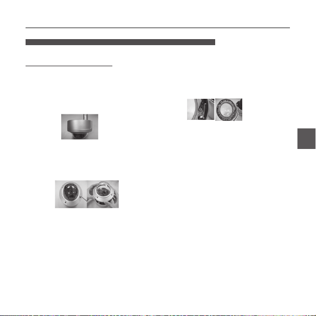
Installing on a pipe
Before installation, you have to be familiar with the above cautions and fi ll in the holes that
are not used for installation.
To install your camera bottom on a pipe
1.
After connecting the power and video cables,
throw them inside the pipeline and screw the male
thread pipe into the female pipe thread in your
camera tightly to fix the
be sure to tape with Tefl on tape before assembly for
waterproofi ng. Be careful for the wiring cable not to
be stuck in the connection area.)
2.
Adjust the angle of the camera in search of a better
view.
1)
Separate the Dome cover using the L-Wrench
provided. (To make loose the screws, rotate
counterclockwise.)
2)
Adjust the lens direction. For more information,
see page 17 “Adjusting the camera direction.”
Main body
. (In this case,
3.
Attach the Dome cover. (Screw the connection bolts
tightly using the L-Wrench for waterproofi ng.)
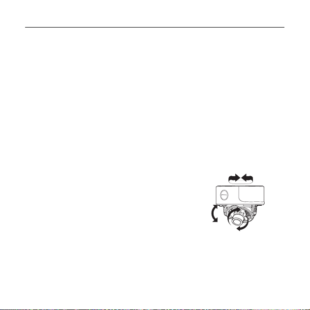
To change the SAMSUNG logo position, move the
location of the connection rubber band as show
below and rotate for assembly. (The rotation limit
is 180 degree.)
Installation
ENG
English – 11
Installation
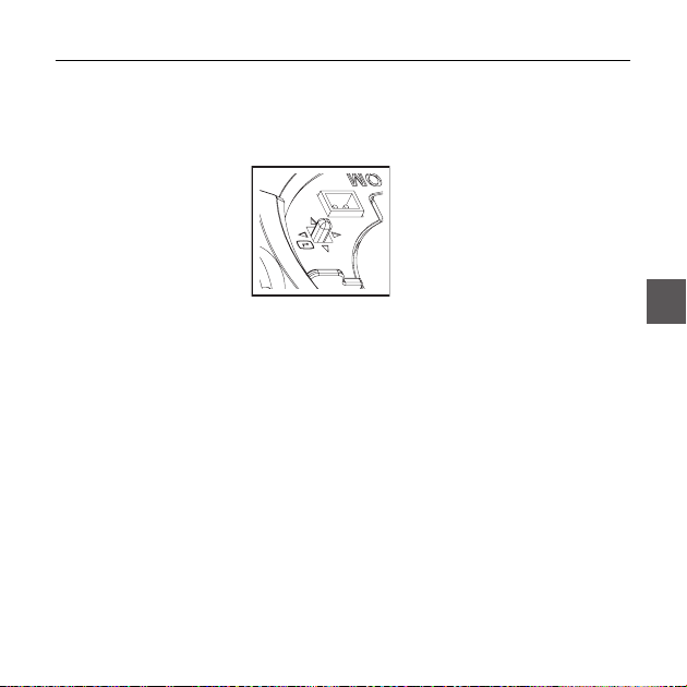
Adjusting the camera direction
When the camera is fi xed on the ceiling, you can adjust the camera viewing angle.
You can rotate your camera leftward or rightward (Panning), and can change the
slope of your camera upward or downward (Tilting).
In case of panning, the rotation limit of your camera is set to 355 degree (100
degree clockwise and 255 degree counterclockwise). The rotation is stopped by
Stopper
the
located on the bottom and rotate in the direction you want, and then fasten them to
fi x the camera.
In case of tilting, you can change the slope of your camera from zero to 90 degree.
However if the slope angle is under 17 degree, you can encounter a partial image
hide problem. To fi x the location after adjusting the tilting angle, use the
screws
To adjust the focus and zoom of your camera, use the
lever
camera lens to see a correct direction image.
12 – DIGITAL COLOR DOME CAMERA
inside of the camera. For panning control, fi rst unfasten two screws
Panning
Tilt fi xing
Focus
and
.
. When you install the camera on the inclined ceiling or wall, you can rotate the
Tilting
Zoom lever
Lens rotation
How to use OSD Menu
USING ICONS IN THE MENU
•
(EXIT)
Exits the menu setting.
Before you exits the menu setting, select SAVE to
save your settings, or select QUIT to cancel.
•
(RET)
Returns to the previous menu.
•
(HOME)
Returns to the main menu.
•
(SAVE)
Used to save your settings of MASK AREA,
PRIVACY ZONE and more.
Once you save your settings, they will remain
even if you select QUIT in the menu.
•
(DEL)
Used to deletes your settings of MASK AREA,
PRIVACY ZONE and more.
Once you delete your settings, they will not be
restored even if you select QUIT in the menu.
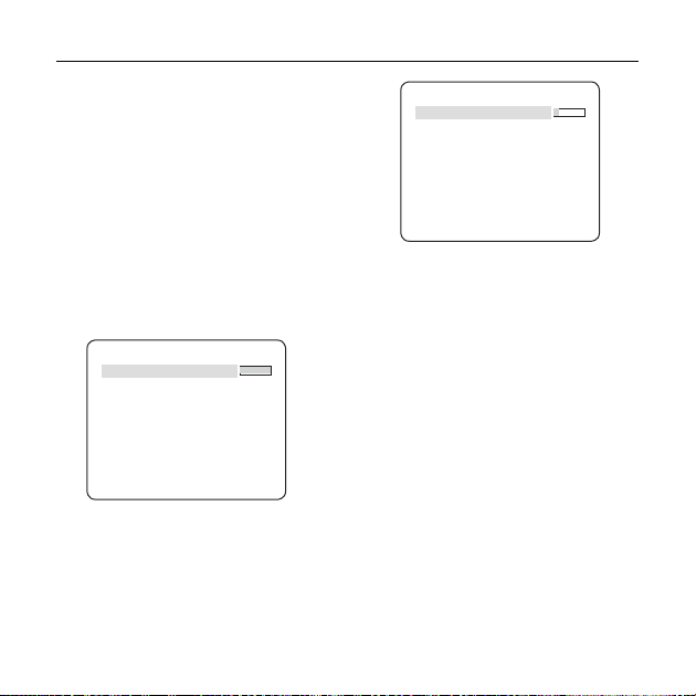
MAIN MENU
PROFILE
•
You can set a mode according to the camera
installation conditions.
CAMERA SET
•
Confi gure Camera related functions and data.
INTELLIGENCE
•
You can confi gure the settings of motion
detection, tracking and more.
PRIVACY ZONE
•
You can confi gure the privacy related settings.
OTHER SET
•
You can confi gure for Factory Defaults, and more.
SYSTEM INFO.
•
Displays the system information including the
camera version and communication settings.
LANGUAGE
•
Select a preferred one from the supported
languages.
MAIN MENU
PROFILE
CAMERA SET
INTELLIGENCE
PRIVACY ZONE
OTHER SET
SYSTEM INFO
LANGUAGE
ENG
English – 13
How to use OSD Menu
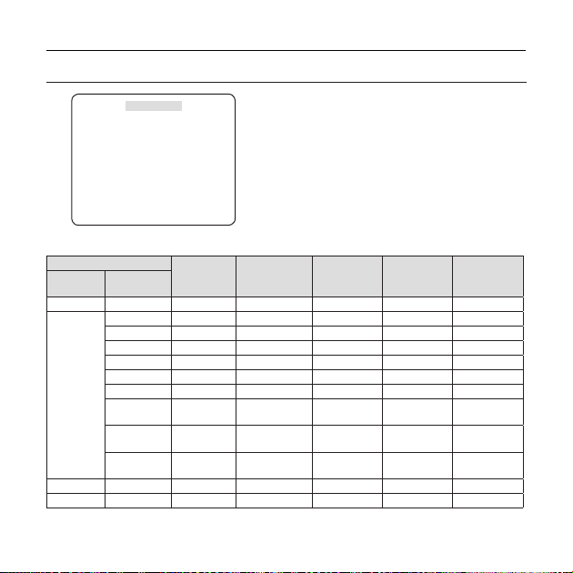
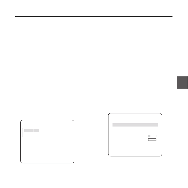
PROFILE
e
PROFILE
f
STANDARD
ITS
BACKLIGHT
DAY/NIGHT
GAMING
CUSTOM
In the PROFILE menu, you can confi gure the following camera settings at once.
CAMERA SET Menu
Previous
MOTION (F.FAST)--- (F.FAST)--- NORM (F.FAST)--- SLOW
Sub-menus
Menu
VPS OFF ON OFF OFF OFF
IRIS ALC ALC ALC ALC ALC
ALC -- ---
BACKLIGHT OFF OFF WDR OFF OFF
WDR -- ---
WDR LEVEL
WHITE BAL
DNR MID MID MID MID MID
14 – DIGITAL COLOR DOME CAMERA
STANDARD ITS BACKLIGHT DAY/NIGHT GAMING
LENSDCDC DCDCDC
LEVEL 0 0 0 0 0
WEIGHT
User setting
allowed
User setting
allowed
User setting
allowed
User setting
allowed
User setting
allowed
User setting
allowed
MID
0
User setting
allowed
User setting
allowed
User setting
allowed
User setting
allowed
User setting
User setting
User setting
allowed
allowed
allowed
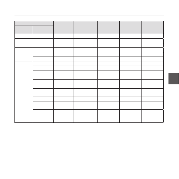
How to use OSD Menu
CAMERA SET Menu
Previous
SHUTTER OFF AUTO1/250 OFF OFF OFF
SENS-UP AUTOx4 AUTOx2 AUTOx4 AUTOx4 AUTOx4
DAY/NIGHT AUTO AUTO DAY AUTO DAY
WHITE BAL DAY DAY/NIGHT DAY DAY/NIGHT DAY
❖
Sub-menus
Menu
XDR MID MID MID MID MID
NIGHT-- ---
DAY -- ---
NIGHT-- ---
BRIGHTNESS
DETAIL 2 2 2 2 2
ITS
It will be set automatically so you can easily check the traffi c conditions.
❖
BACKLIGHT
It will be set automatically so you can distinguish the object from the background in a severe backlighting scene.
❖
DAY/NIGHT
It will be set automatically so it optimizes to the day or night conditions, respectively.
GAMING
❖
STANDARD ITS BACKLIGHT DAY/NIGHT GAMING
BURST OFF ON OFF OFF OFF
MODE ATW2 ATW1 ATW1 ATW1 ATW1
RED00 000
BLUE 0 0 0 0 0
User setting
allowed
MODE OFF ATW2 OFF ATW2 OFF
User setting
RED
allowed
User setting
BLUE
allowed
MID
User setting
allowed
User setting
0
0
allowed
User setting
allowed
MID
User setting
allowed
User setting
0
0
allowed
User setting
allowed
English – 15
ENG

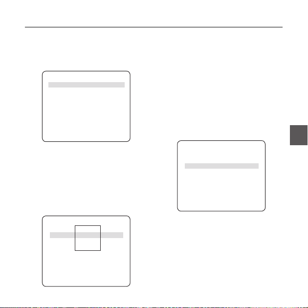
How to use OSD Menu
CAMERA SETUP
eCAMERA SETf
CAMERA ID OFF
VPS OFF
IRIS ALC
MOTION (F.FAST)--DNR MID
SHUTTER OFF
SENS-UP AUTO X4
FLICKERLESS (OFF)--XDR MID
DAY/NIGHT AUTO
WHITE BAL
DIGITAL ZOOM
DETAIL [2]
V-SYNC INT
AGC COLOR SUP
REVERSE H/V
POSI/NEGA +
PIP OFF
DIS OFF
16 – DIGITAL COLOR DOME CAMERA
d
c
OFF
LOW
d
c
Setup the general functions of zoom camera module.
Use the
cdef
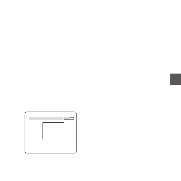
CAMERA ID [OFF, ON]
❖
ABCDEFGHIJKLMNOPQRSTUVWXYZ0
123456789 :?-+*()/
SP
ffee
CAMERA-1..................
...........................
The CAMERA ID menu is used for you to assign
a unique name to a camera. If you press the
SETUP switch with the CAMERA ID menu
selected, you will see the appropriate screen.
You can enter up to 54 alphanumeric or
special characters for the CAMERA ID. Select
LOCATION and press the SETUP switch to
move the display position of the CAMERA ID.
❖
VPS [OFF, ON]
If you set the VPS (Virtual Progressive Scan)
option, the camera will display the image in
progressive format.
❖
IRIS [ALC]
The IRIS menu is used if you want to adjust the
intensity of radiation incoming to the camera.
switch to select a menu item.
CAMERA ID
SP LOCATION
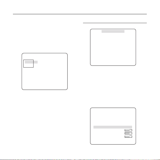
ALC (Automatic Light Control)
•
① If you press the SETUP switch with an ALC-
based sub menu selected, you will see the
appropriate screen.
ALC
LEVEL [00]----I---BACKLIGHT OFF
The LEVEL menu is used to adjust the
overall brightness, where “+” will increase the
brightness and “–” will decrease it.
② If you set the BACKLIGHT option to BLC,
you will see a menu where you can set the
BLC area.
you can set the desired BLC zone by defi ning
the size and location.
ALC
LEVEL [00]----I---BACKLIGHT BLC
AREA USER
<SIZE>
<LOCATION>
How to use OSD Menu
If you use an ordinary camera in a scene
with an intensive backlight, the object will be
displayed dark on the monitor affected by the
backlight. To solve this problem, you can use
the BLC(Back Light Compensation) function
to improve the sharpness of the image in
such a high contrast scene.
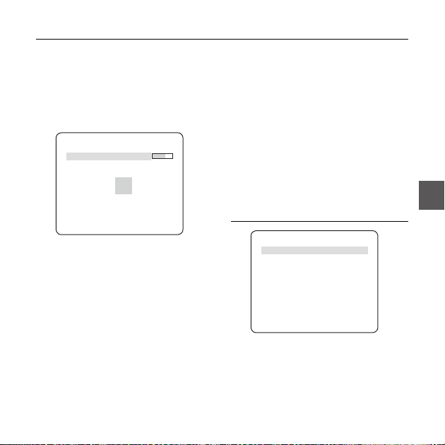
If you set the BACKLIGHT option to WDR, you will
③
see a menu where you can set the WDR options.
You can adjust the shutter speed in WDR LEVEL
and the brightness in WEIGHT.
You can also select any of OUTDOOR, and
INDOOR in WHITE BAL.
ALC
LENS DC
LEVEL [ 00]----I---BACKLIGHT WDR
WEIGHT MID
WDR LEVEL [ 0]----I--- WHITE BAL INDOOR
WDR(Wide Dynamic Range) extends the gain range of
the screen that is mostly useful if you take a simultaneous
picture of both indoor and outside of the window.
Namely, it improves the sharpness of the
picture in outdoor scenery as well as indoor.
Note :
If you use the VPS (Virtual Progressive Scan) function, the CCD
–
reads differently so you can not use WDR simultaneously.
If you set VPS to ON, WDR will be automatically set to OFF.
English – 17
ENG
How to use OSD Menu
AGC
❖
[OFF, VERY LOW, LOW, MID, HIGH, VERY
HIGH, USER, FIX]
The AGC (Auto Gain Control) menu is used to
set the AGC level of the camera. When the AGC
is active, the camera automatically increases the
sensitivity by amplifying the Video signal when
the strength of the signal falls below the normal
value.
If OFF or FIX mode is selected in the SENS-UP
menu, you can specify the AGC level.
If you press the SETUP switch with a USER
sub menu selected, you will see the appropriate
screen.
AGC USER
LEVEL [16]
In USER mode, you can break down the level in
16 steps from VERY LOW to VERY HIGH to your
preference.
18 – DIGITAL COLOR DOME CAMERA
LEVEL [01]
If you press the SETUP switch with a FIX sub
menu selected, you will see the appropriate screen.
As a fi xed value of the AGC gain is used in FIX
mode, you can select one of the 16 detailed levels
from VERY LOW to VERY HIGH before fi xing it.
FIX mode is not available if you set the
BACKLIGHT function to WDR.
Note :
If the DAY/NIGHT menu of the CAMERA SET is set to
–
AUTO, the AGC menu will be deactivated.
If FLICKERLESS is set to ON, the AGC FIX mode will be disabled.
–
MOTION
❖
The MOTION menu is used to adjust the strength
of the AGC level for a control of the camera motion.
This is available only if the SENS-UP menu is set
to AUTO.
You can select one from S.SLOW, SLOW, NORM,
FAST and F.FAST for the AGC level.
If you monitor a fast moving object in a low contrast
scene, select F.FAST while select S.SLOW for a
hardly moving object in the same lighting condition.
AGC FIX
[S.SLOW, SLOW, NORM, FAST, F.FAST]

How to use OSD Menu
Note :
If the DAY/NIGHT menu of the CAMERA SET is set to
–
AUTO, the MOTION menu will be deactivated.
DNR
❖
You can confi gure the DNR (Digital Noise
Reduction) related settings.
Reduces the noise on the screen.
This is especially useful for a severely distorted
screen.
You can set the level if you set DNR to USER.
SHUTTER
❖
[OFF, AUTO 1/100(PAL:1/120), AUTO 1/250,
AUTO 1/500, AUTO 1/1000, AUTO 1/2000, AUTO
1/4000, AUTO 1/10K , 1/100(PAL:1/120), 1/250,
1/500, 1/1000, 1/2000, 1/4000, 1/10K , EXT]
The SHUTTER menu is used to confi gure settings
of the fi xed / auto high-speed electronic shutter.
You can select one of 7 options from 1/100(PAL:1/120)
to 1/10K for the fi xed high speed electronic shutter,
which is mostly used for imaging a fast moving object.
The auto high speed electronic shutter operates
as the fi xed high speed shutter in a high contrast
scene but automatically focuses the target if the
iris opens fully in a low contrast scene like in ELC
mode. When it gets brighter back, the mode will
switch to the fi xed high speed electronic shutter
mode.
However, the auto high speed shutter operates
properly only in a camera featuring a DC or VIDEO lens.
[OFF,LOW,MID,HIGH, USER(1~16)]
Note :
If the SENS-UP function is set to AUTO, only items of
–
OFF and AUTO are available in the SHUTTER menu.
If the SENS-UP mode is set to FIX, the SHUTTER menu
–
will be deactivated.
–
If the FLICKERLESS function is set to ON, the SHUTTER menu
will be deactivated.
SENS-UP
❖
[OFF, AUTO X2, AUTO X4, AUTO X6, AUTO
X8, AUTO X12, AUTO X16, AUTO X24, AUTO
X32, AUTO X48, AUTO X64, AUTO X96, AUTO
X128, AUTO X256, AUTO X512, FIX X2, FIX
X4, FIX X6, FIX X8, FIX X12, FIX X16, FIX X24,
FIX X32, FIX X48, FIX X64, FIX X96, FIX X128,
FIX X256, FIX X512]
Automatically detects the ambient level of
darkness in the dark or low contrast scene to
extend the accumulated time, keeping the image
bright and sharp; It can be also used as FIX mode.
Note :
If the SHUTTER menu is set to fi xed electronic shutter
–
mode, the SENS-UP menu will not be available.
If FLICKERLESS is set to ON, the FIX mode of the SENS-
–
UP menu will be disabled.
If the SHUTTER menu is set to AUTO, the SENS-UP
–
menu can be set to either OFF or AUTO mode.
If the BACKLIGHT function is set to WDR, the SENS-UP menu
–
can not be set to FIX.
English – 19
ENG

How to use OSD Menu
FLICKERLESS [OFF, ON]
❖
If set to ON, the shutter speed will be fi xed to
1/100(PAL:1/120) second. This will prevent possible screen
distortion due to a mismatch between the vertical sync
frequency and the blinking frequency of the lighting.
Note :
If the SHUTTER menu is set to AUTO or FIX mode, the
–
FLICKERLESS menu will not be available.
If the SENS-UP function is set to FIX mode, the Flickerless
–
menu will be deactivated.
If AGC is set to FIX mode, the FLICKERLESS function will
–
be disabled.
XDR (eXtended Dynamic Range)
❖
[OFF, LOW, MID, HIGH]
Actively controls the gamma compensation in the
way it operates the ambient luminance contrast
in a certain pixel unit to determine the optimal
visibility.
Select one from OFF, LOW, MID and HIGH.
Closing to HIGH will increase the compensation
level.
DAY/NIGHT
❖
DAY
•
If set to DAY, it will be fi xed to DAY mode
regardless of the ambient conditions.
•
NIGHT
If set to NIGHT, it will be fi xed to Black-and-White
mode regardless of the ambient conditions.
[DAY,NIGHT,AUTO,EXT]
20 – DIGITAL COLOR DOME CAMERA
If you press the SETUP switch with a NIGHT sub
menu selected, you will see a menu where you can
set Burst to OFF/ON.
If BURST is set to ON, the Burst signal will output
together with the black-and-white composite video
signal. If BURST is set to OFF, the Burst signal does
not output.
You can set the BURST option to OFF/ON, or
select to output the Burst signal in NIGHT mode.
AUTO
•
The camera will automatically switch between
DAY and NIGHT mode, according to the lighting
condition.
If you press the SETUP switch with an AUTObased sub menu selected, you will see the
appropriate screen.
BURST OFF
DAYÆNIGHT
BRIGHTNESS MID
DWELL TIME 2S
NIGHTÆDAY
BRIGHTNESS MID
DWELL TIME 5S
MASK AREA 1 2
You can set the BURST option to OFF/ON, or
select to output the Burst signal in NIGHT mode.
The BRIGHTNESS of DAYÆNIGHT sets the
brightness degree of color to BW switching,
for which you can select from LOW, MID, and
AUTO
How to use OSD Menu
HIGH. As you adjust it from HIGH to LOW, the
screen switches to black and white mode under
the darker situation.
DWELL TIME of DAYÆNIGHT sets the time to
maintain switched black and white mode.
The BRIGHTNESS of NIGHTÆDAY sets the
brightness degree of BW to color switching, for
which you can select from LOW, MID, and HIGH.
As you adjust it from HIGH to LOW, the screen
switches to color mode under the darker situation.
DWELL TIME of NIGHTÆDAY sets the time to
maintain switched color mode.
The MASK AREA menu is used to prevent
unintended mode switching or inability of
determining the switching due to existence of
high spot light source at night.
If you press the SETUP switch in item 1 or 2 of
the MASK AREA menu, you will see a menu
where you can specify an area to MASK.
MASK AREA
<SIZE>
<LOCATION>
You can specify MASK 1 and 2 simultaneously.
The MASK is only for determining the mode
switching, and any excessive bright area at night
will be excluded by the confi gured MASK.
Note :
–
If BACKLIGHT is set to BLC, the MASK AREA function will
be deactivated.
DAY
•
This enables an auto switch between DAY and NIGHT
mode using the interface with the external sensor.
WHITE BAL [DAY/NIGHT]
❖
If you want to adjust the color scheme, use the
WHITE BALANCE function.
DAY
•
In DAY mode, you can set the color values of
RED and BLUE. The screen will be displayed in
colors according to your settings.
WHITE BAL
DAY/NIGHT DAY
MODE AWC
RED [00]----I--- BLUE [00]----I--- R-GAIN [0248]
B-GAIN [0247]
Note :
You can set the values of R-GAIN and B-GAIN only in
–
AWC mode.
English – 21
ENG

How to use OSD Menu
NIGHT
•
Use the NIGHT mode if you want to set the white
balance differently according to the ambient
luminance.
If the NIGHT mode is set to OFF, the white
balance will always operate as set in DAY mode;
if not to OFF, the camera will switch to as set in
DAY/NIGHT mode according to the brightness.
In NIGHT mode, you can set the values of RED,
BLUE and BRIGHTNESS. The screen will be
displayed in colors according to your settings.
WHITE BAL
DAY/NIGHT NIGHT
BRIGHTNESS MID
MODE AWC
RED [00]----I--- BLUE [00]----I--- R-GAIN [0248]
B-GAIN [0247]
Note :
You can set the values of R-GAIN and B-GAIN only in
–
AWC mode.
If AGC is set to OFF or FIX, you can not access the
–
NIGHT menu.
For adjusting the white balance, the following
–
5 modes are provided:
ATW1(Auto Tracing White Balance mode
•
1): The camera can automatically adjust the
color temperature in real time, according to
22 – DIGITAL COLOR DOME CAMERA
the ambient conditions. The color temperature
ranges from approx. 2500K to 9300K.
•
ATW2: The color temperature ranges from
approx. 2,000K to 10,000K.
•
AWC ( Auto White Balance Control): If you
press the SETUP switch in the appropriate item
position, Auto White Balance will perform once.
•
3200K : Set color temperature to 3200K
•
5600K : Set color temperature to 5600K
–
RED : Adjusts the strength of the red color.
BLUE : Adjusts the strength of the blue color.
–
R-GAIN/B-GAIN : Enables you to set the current
–
color temperature manually.
BRIGHTNESS : Select a brightness level in
–
switching from setting in DAY mode to setting in
NIGHT mode.
DIGITAL ZOOM [ON/OFF]
❖
You can set the digital zoom factor and position.
If you press the SETUP switch with the DIGITAL
ZOOM function set to ON, you will see the
appropriate screen.
When the zoom factor and position are defi ned,
the digital zoom function will operate.
How to use OSD Menu
DIGITAL ZOOM
RATIO [X1.0]
< LOCATION >
-
LOCATION : If you press the SETUP switch in the
condition where the image is enlarged as much as the
ratio setting, you can watch an invisible area of the
effective screen as well using the
Note :
If the digital zoom factor is set to larger than 1x, the FENCE
–
function will be deactivated.
The DIGITAL ZOOM function enlarges the pixel itself, which can
cause deterioration of the quality.
DETAIL [0~3]
❖
Controls the horizontal or vertical distinction.
V-SYNC [INT, LINE]
❖
Select the vertical sync mode for INT or LINE.
If you select INT, the camera will use the internal
synchronization.
If selecting LINE, the camera will use the external
power source frequency for the synchronization.
You can adjust the LL-PHASE.
cdef
switch.
Note :
Use of DC 12V will fi x V-SYNC to INT, which can not be
–
changed.
AGC COLOR SUP [LOW , MID, HIGH]
❖
Adjust the color scheme according to the AGC value.
REVERSE [OFF, H, V, H/V]
❖
Mirrors video signals horizontally, vertically, or both.
POSI/NEGA [+, -]
❖
Output as it is or mirror the video brightness signal.
PIP [OFF, ON]
❖
Displays a sub image together with the main image on
the same screen using the Picture In Picture function.
Note :
If more than one privacy zone is set and the PRIVACY SET is
–
set to ON, the PIP function will be deactivated.
If the INTELLIGENCE function is set to FENCE mode, the PIP
–
menu will be deactivated.
DIS [OFF, ON]
❖
Digital Image Stabilization will set the anti-shake
compensation.
Note :
If you set DIS to ON, the compensation area will be enlarged as
–
set in the digital zoom factor.
If you set the digital zoom factor to greater than the enlarged
zoom factor for the compensation, the DIS function will be
deactivated.
English – 23
ENG
How to use OSD Menu
FENCE
INTELLIGENCE
eINTELLIGENCEf
MOTION OFF
ADVANCED OFF
MASK AREA
DISPLAY ON
SENSITIVITY [4]
RESOLUTION [5]
You can set the motion detection and tracking in the
INTELLIGENCE menu.
MOTION
❖
TRACKING
•
Detects and tracks a moving object.
DETECTION
•
Detects a moving object.
Note :
If it is set to DETECTION, you can not set such functions as
–
FIXED/MOVED and FENCE in the ADVANCED menu.
ADVANCED
❖
Detects a motion of an object and displays an
image of any moving object before tracking the
moving route.
24 – DIGITAL COLOR DOME CAMERA
1 2 3 4
[OFF,TRACKING,DETECTION]
[OFF, FIXED/MOVED, FENCE]
•
This is to detect if a moving object passes
through the specifi ed LINE or AREA.
In a condition where a moving object is detected
in an analysis of the previous and current frames
whose movement overlaps a certain area, the
system displays “PASS” if the object’s center line
passes through the line while it displays “ENTER” or
“EXIT” if the center point passes through the area.
LINE OFF
AREA OFF
You can set the position and detection direction of the
LINE, and the size and position of the AREA.
- How to set the line
PIXEL LEVEL [4]
<POINT>
DIRECTION §¨
FENCE
LINE
How to use OSD Menu
① If you press the SETUP switch with the LINE
option set to ON, you can specify the position
and detection direction of the line.
② If you change the PIXEL LEVEL for setting
the position, specify the pixel that moves by a
single pressure of the
In <POINT>, you can specify the fi rst position of
③
the line by pressing the SETUP switch once, and
the second position by pressing the switch again.
Use the
cdef
position.
Set each position of the two points and press the
SETUP switch to complete the positioning.
④
If you change the DIRECTION, you can specify
the detection direction. The detection direction
based on the defi ned two points will be
displayed on the screen.
- How to set the area
PIXEL LEVEL [4]
<SIZE>
<LOCATION>
① If you press the SETUP switch with the AREA
option set to ON, you can specify the position
cdef
switch to specify the
AREA
switch.
and size of the area.
② If you change the PIXEL LEVEL for setting
the position, specify the pixel that moves by a
single pressure of the
In <SIZE>, press the SETUP switch and use
③
the
cdef
Press the SETUP switch again to complete the
sizing.
④
In <LOCATION>, press the SETUP switch and
use the
cdef
Press the SETUP switch again to complete
the positioning.
Note :
If you set the LINE of the FENCE to ON, PRIVACY 12 will
–
not be available.
Functions of FENCE, PIP, DIS and DIGITAL ZOOM (if the
digital zoom factor is set to larger than 1x) can not be
used simultaneously.
In the boundary of the defi ned AREA and LINE, a FENCE
–
detection error may occur if two or more moving objects
overlap with each other or one object separates in
multiple directions.
FIXED/MOVED
•
If an object on the screen suddenly disappears or
an object comes out of nowhere and stays for a
certain time, the area will be displayed.
A detection (FIXED/MOVED) error may occur if :
- multiple motions occur continuously in random
directions
cdef
switch.
switch to adjust the size.
switch to specify the position.
English – 25
ENG
How to use OSD Menu
- a fi xed object moves in one position continuously
- a second object screens the fi rst moving object
❖
MASK AREA [1~4]
Specify a detection exception area to mask.
Select a mask number and specify the size and
position.
MASK AREA
<SIZE>
<LOCATION>
❖
DISPLAY [ON, OFF]
With the DISPLAY option set to ON, a motion or
a set ADVANCED function will be displayed on
the screen, if detected.
❖
SENSITIVITY [1~7]
Set the sensitivity of the motion detection.
❖
RESOLUTION [1~5]
If setting it to high, the camera can detect even a
trivial movement of the target.
26 – DIGITAL COLOR DOME CAMERA
PRIVACY ZONE SETUP
1 2 3 4 5 6
7 8 9 10 11
PRIVACY SET ON
STYLE
The PRIVACY function will protect your privacy by
screening the privacy area that you have specifi ed
during monitoring. You can specify up to 12 privacy
zones.
If you set the PRIVACY SET to ON, your PRIVACY
ZONE settings will be applied.
You can change the style to adjust the mosaic size
and color of the PRIVACY ZONE.
1 2 3 4 5 6
7 8 9 10 11
PRIVACY SET ON
STYLE COLOR
Y-LEVEL [128]
RED [128]
BLUE [128]
ePRIVACY ZONEf
MOSAIC1
ePRIVACY ZONEf
12
12
How to use OSD Menu
Use the
cdef
PRIVACY 1 through 12.
Select one from PRIVACY 1~12 and press the
SETUP switch to confi rm your setting. You can
specify a pixel that moves as you change the PIXEL
LEVEL to set the position.
- How to set the point
You can set each position of the 4 points.
① If you press the SETUP switch in <POINT>,
you will see the points available in the
PRIVACY ZONE. Each time you press the
SETUP switch, the points available will move.
② Use the
of each point. Set each position of the four
points and press the SETUP switch to
complete the positioning.
- How to set the position
You can move the position of the overall area.
switch to select one from
PRIVACY ZONE SET1
PIXEL LEVEL [4]
<POINT>
<POSITION>
cdef
switch to set the position
① By pressing the SETUP switch in
<POSITION>, you can move the overall
position of the privacy zone.
cdef
② Use the
position and press the SETUP switch to
confi rm it.
Note :
If more than one PRIVACY ZONE is specifi ed and the
–
PRIVACY SET is set to ON, the PIP function will be
deactivated.
If the 12th PRIVACY ZONE is specifi ed, the LINE function
–
of FENCE will be deactivated.
switch to move the
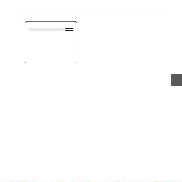
OTHER SET
eOTHER SETf
EXTERNAL TRG OFF
FACTORY DEFAULTS
OSD COLOR BW
EXTERNAL TRG
❖
Set the EXTERNAL TRG menu to ON and press
the SETUP switch to display the appropriate
screen.
English – 27
ENG

How to use OSD Menu
EXTERNAL TRG
STILL TIME OFF
DELAY TIME FIX
You can set the STILL TIME to 0~4 seconds.
If DELAY TIME is set to FIX, the DELAY TIME will
be set in sync with the STILL TIME; if set to USER,
the DELAY TIME will be set to your setting.
Note :
If VPS is set to OFF, the EXTERNAL TRG menu will be
–
deactivated.
FACTORY DEFAULTS
❖
All the settings will be restored to the factory
default.
However, the settings of PROTOCOL, BAUD
RATE, ADDRESS and LANGUAGE will not be
restored to the default.
OSD COLOR [BW, R/G/B]
❖
You can set the OSD(On-screen Display) color to
COLOR or B/W.
28 – DIGITAL COLOR DOME CAMERA
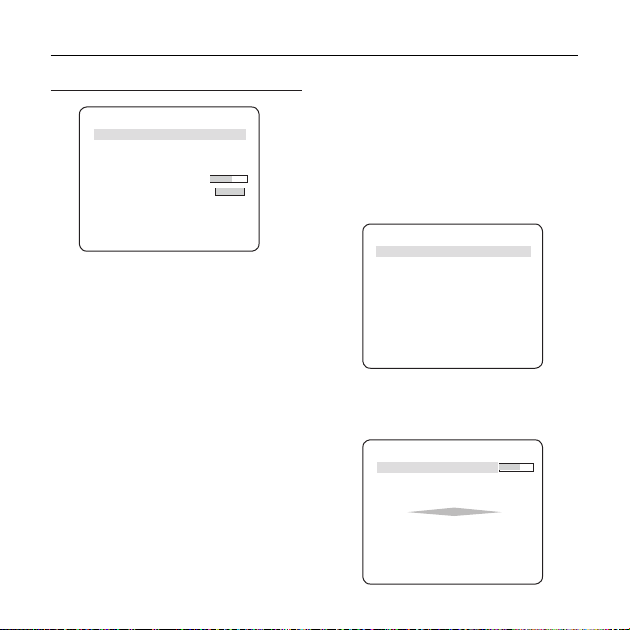
SYSTEM INFORMATION
TYPE 3_VAR_WDR_
SERIAL NO.
CAMERA VER. 0.50_090101
You can check the system information such as
SERIAL NO and CAMERA VER.
LANGUAGE
The camera supports 5 different languages.
Select a preferred language.
eSYSTEM INFOf
000000000000000
eLANGUAGEf
ENGLISH
FRANÇAIS
DEUTSCH
ESPAÑOL
ITALIANO
P

Initial Confi guration Table
❖
Camera Confi guration
•
CAMERA ID OFF
VPS OFF
IRIS ALC
AGC VERY HIGH
MOTION (F.FAST)
DNR MID
SHUTTER OFF
SENS-UP
AUTO x4
FLICKERLESS (OFF)
XDR MID
DAY/NIGHT AUTO
DIGITAL ZOOM OFF
DETAIL [2]
AGC COLOR SUP MID
REVERSE H/V
POSI/NEGA +
PIP OFF
DIS OFF
V-SYNC INT
How to use OSD Menu
ENG
English – 29

Specifi cations
SPECIFICATIONS
Items Sub-items SCC-B5397N/SCC-5399N
Camera Type
Image
Scanning
Min. Scene
Illumination
Functions
Device 1/3” Super-HAD PS CCD
Pixels
System Interlace/Progressive
Scanning Line 525 lines
Frame 30frame/1sec
Horizontal
Frequency
Vertical
Frequency
512 times 1.2 50 IRE 0.0008 Lux 0.00008 Lux
512 times 1.2 30 IRE 0.0005 Lux 0.00005 Lux
512 times 1.2 15 IRE 0.00023 Lux 0.000023 Lux
Number of Privacy Zone 12 (Polygonal Method)
Day/Night DAY/NIGHT/AUTO/EXT
Motion Detection OFF/Tracking/Detection
eXtended Dynamic Range(XDR) Off/On (Level Setting)
Wide Dynamic Range(WDR) Off/On (x128)
Virtual Progressive Scan(VPS) Off/On
D-Zoom x1 ~ x16 (x0.1 STEP)
PIP Off/On
High Speed Shutter 1/60 ~ 1/10Ksec (OSD/External Control)
Flickerless Off/On
30 – DIGITAL COLOR DOME CAMERA
CCTV Camera (WDR & DAY/NIGHT)
Total 811 x 508
Effective 768 x 494
Internal Mode 15,734 Hz
Line-lock Mode 15,750 Hz
Internal Mode 59.94 Hz
Line-lock Mode 60 Hz
Condition Min. Scene illumination
Sens-up F No. Level DAY NIGHT
OFF 1.2 50 IRE 0.4 Lux 0.04 Lux
OFF 1.2 30 IRE 0.24 Lux 0.024 Lux
OFF 1.2 15 IRE 0.12 Lux 0.012 Lux

Specifi cations
Items Sub-items SCC-B5397N/SCC-5399N
Sens-Up x2 ~ x512
AGC Off/On (Max.Level Setting)
Line Lock Off/On (Phase Control)
Camera ID Off/On (Max.54ea/2Line)
White Balance ATW1/ATW2/AWC/3200K/5600K
Digital Noise Reduction(DNR) Off/On (Adaptive 3D+2D)
Resolution
Video Output
S/N Ratio
Lens
PAN
TILT
Remote
Control
Environmental
Conditions
Power
Physical
Specifi cation
Digital Image Stabilization(DIS)
Intelligent Video Fixed/Moved, Fence
Etc. Function Detail, Reverse(H/V), Posi/Nega
Horizontal 600 TV Lines
Vertical 350 TV Lines
- VBS 1.0Vp-p, 75 Ω
S/N Ratio Approx. 52dB
Lens Drive Type
Range
Range 0 ~ 90°
Coaxitron (Data On Coax cable) Yes (with SCX-RD100)
Operating Temperature -10˚C ~ +50˚C
Humidity Less than 90%
Power Requirement
Power Consumption 2.6W
Dimensions (Ø x H) 150(Ø) x 121(H)mm
Weight 980g
Color White
Auto Iris (DC)
SCC-B5397 : focal length = 2.5 to 6.0mm / Aperture ratio = F 1.2
SCC-B5399 : focal length = 2.8 to 11.0mm / Aperture ratio = F 1.2
0 ~ 355°(100° in CW(Clockwise) direction,
255° in CCW (Counterclockwise) direction)
Off/On
AC24V ± 10%(60Hz ± 0.3Hz)
DC12V ± 10%
ENG
English – 31

Specifi cations
Items Sub-items SCC-B5397P/SCC-5399P
Camera Type
Image
Scanning
Min. Scene
Illumination
Functions
Device 1/3” Super-HAD PS CCD
Pixels
System Interlace/Progressive
Scanning Line 625 lines
Frame 25frame/1sec
Horizontal
Frequency
Vertical
Frequency
512 times 1.2 50 IRE 0.0008 Lux 0.00008 Lux
512 times 1.2 30 IRE 0.0005 Lux 0.00005 Lux
512 times 1.2 15 IRE 0.00023 Lux 0.000023 Lux
Number of Privacy Zone 12 (Polygonal Method)
Day/Night DAY/NIGHT/AUTO/EXT
Motion Detection OFF/Tracking/Detection
eXtended Dynamic Range(XDR) Off/On (Level Setting)
Wide Dynamic Range(WDR) Off/On (x160)
Virtual Progressive Scan(VPS) Off/On
D-Zoom Max. x16
PIP Off/On
High Speed Shutter 1/50 ~ 1/10Ksec (OSD/External Control)
Flickerless Off/On
Sens-Up x2 ~ x512
BLC Off/On (Area Setting)
32 – DIGITAL COLOR DOME CAMERA
CCTV Camera (WDR & DAY/NIGHT)
Total 795 x 596
Effective 752 x 582
Internal Mode 15,625 Hz
Line-lock Mode 15,625 Hz
Internal Mode 50 Hz
Line-lock Mode 50 Hz
Condition Min. Scene illumination
Sens-up F No. Level DAY NIGHT
OFF 1.2 50 IRE 0.4 Lux 0.04 Lux
OFF 1.2 30 IRE 0.24 Lux 0.024 Lux
OFF 1.2 15 IRE 0.12 Lux 0.012 Lux

Specifi cations
Items Sub-items SCC-B5397P/SCC-5399P
AGC Off/On (Max.Level Setting)
Line Lock Off/On (Phase Control)
Camera ID Off/On (Max.54ea/2Line)
White Balance ATW1/ATW2/AWC/3200K/5600K
Digital Noise Reduction(DNR) Off/On (Adaptive 3D+2D)
Resolution
Video Output
S/N Ratio
Lens
PAN
TILT
Remote
Control
Environmental
Conditions
Power
Physical
Specifi cation
Digital Image Stabilization(DIS)
Intelligent Video Fixed/Moved, Fence
Etc. Function Detail, Reverse(H/V), Posi/Nega
Horizontal 600 TV Lines
Vertical 350 TV Lines
- VBS 1.0Vp-p, 75 Ω
S/N Ratio Approx. 52dB
Lens Drive Type
Range
Range 0 ~ 90°
Coaxitron (Data On Coax cable) Yes (with SCX-RD100)
Operating Temperature -10˚C ~ +50˚C
Humidity Less than 90%
Power Requirement
Power Consumption 2.6W
Dimensions (Ø x H) 150(Ø) x 121(H)mm
Weight 980g
Color White
Auto Iris (DC)
SCC-B5397 : focal length = 2.5 to 6.0mm / Aperture ratio = F 1.2
SCC-B5399 : focal length = 2.8 to 11.0mm / Aperture ratio = F 1.2
0 ~ 355°(100° in CW(Clockwise) direction,
255° in CCW (Counterclockwise) direction)
Off/On
AC24V ± 10%(50Hz±0.3Hz)
DC12V ± 10%
ENG
English – 33

Correct Disposal of This Product (Waste Electrical & Electronic Equipment)
(Applicable in the European Union and other European countries with separate collection systems)
This marking on the product, accessories or literature indicates that the product and its electronic accessories
(e.g. charger, headset, USB cable) should not be disposed of with other household waste at the end of their
working life. To prevent possible harm to the environment or human health from uncontrolled waste disposal,
please separate these items from other types of waste and recycle them responsibly to promote the sustainable
reuse of material resources.
Household users should contact either the retailer where they purchased this product, or their local government
office, for details of where and how they can take these items for environmentally safe recycling.
Business users should contact their supplier and check the terms and conditions of the purchase contract.
This product and its electronic accessories should not be mixed with other commercial wastes for disposal.

SCC-B5397
SCC-B5399
CAMERA DÔME
NUMERIQUE COULEUR
Manuel d’utilisation
Imaginez les possibilités
Nous vous remercions d’avoir choisi ce produit Samsung.
Pour bénéfi cier d’un service plus complet,
veuillez enregistrer votre produit sur le site
www.samsungsecurity.com
FRE

Informations relatives à la sécurité
ATTENTION
RISQUE DE ECHOC ELECTRIQUE
NEPAS OUVRIR
ATTENTION: POUR REDUIRE LES RISQUES DE CHOCS ELECTRIQUES, NE RETIREZ PAS LE COUVERCLE (OU LA PARTIE
ARRIERE) LES PIECES INTERIEURES NE SONT PAS ACCESSIBLES A L’UTILISATEUR. FAITES APPEL AU
PERSONNEL DE MAINTENANCE QUALIFIE.
Ce symbole indique la présence, dans cette unité, d’une tension élevée et avise des
risques de décharge électrique existants.
Ce symbole indique la présence, dans cette unité, d’une tension élevée et avise des
risques de décharge électrique existants.
ATTENTION
Afi n de réduire le risque d’incendie ou de décharge électrique, n’exposez pas cet appareil à la
•
pluie ni à l’humidité.
ATTENTION
Assurez-vous d’utiliser uniquement l’adaptateur standard spécifi é dans la fi che des
1.
caractéristiques techniques. Utiliser tout autre adaptateur peut provoquer des risques d’incendie
ou des chocs électriques et endommager le produit.
Un branchement incorrect de l’alimentation électrique ou un mauvais remplacement de la pile
2.
peut provoquer des risques d’incendie, des chocs électriques ou des dommages au produit.
Ne pas connecter plusieurs caméras à un seul adaptateur. Dépasser la capacité peut générer
3.
une chaleur anormale ou un risque d’incendie.
2 – CAMERA DÔME NUMERIQUE COULEUR

Informations relatives à la sécurité
Branchez correctement le cordon d’alimentation dans la prise. Une mauvaise connexion peut
4.
provoquer des risques d’incendie.
Lors de l’installation de la caméra, attachez-la fermement et en toute sécurité. Une caméra qui
5.
tombe peut causer des blessures
Ne placez pas d’objets conducteurs (tournevis, pièces de monnaie, objets en métal, etc...par
6.
exemple) ou des récipients remplis d’eau sur la caméra. Cela peut causer des blessures dues au
feu, au choc électrique ou à la chute d’objets.
7.
Ne pas installez l’appareil dans des lieux humides, poussiéreux ou couverts de suie. Cela peut
provoquer des risques d’incendie ou des chocs électriques.
8.
Si vous constatez une odeur ou une fumée inhabituelle provenant de l’appareil, arrêtez
immédiatement son utilisation. Dans de tel cas, déconnectez immédiatement la source
d’alimentation et contactez le centre de maintenance. Si vous continuez à utiliser le produit dans
de telle condition, cela peut provoquer des risques d’incendie ou des chocs électriques.
9.
Si ce produit ne fonctionne pas normalement, contactez le centre de maintenance le plus
proche. Ne jamais démonter ou modifi er le produit de quelque manière que ce soit. (SAMSUNG
n’est pas responsable des problèmes causés par des modifi cations ou des tentatives de
réparation non autorisées.)
10.
Lors du nettoyage, ne pas diriger l’eau directement sur les pièces de l’appareil. Cela peut
provoquer des risques d’incendie ou des chocs électriques.
Français – 3
FRE

Informations relatives à la sécurité
MISE EN GARDE
Ne pas faire tomber des objets sur le produit ou lui faire subir des chocs. Eloignez le produit des
1.
emplacements soumis aux vibrations ou interférences magnétiques excessives.
Ne pas installer le produit à des emplacements soumis aux températures élevées (supérieures
2.
à 50 °C), aux températures faibles (inférieures à -10°C), ou à une humidité élevée. Cela peut
provoquer des risques d’incendie ou des chocs électriques.
Si vous désirez changer le produit de place, assurez-vous de le mettre hors tension, déplacez-le
3.
et réinstallez-le.
Débranchez le cordon d’alimentation de la prise lorsqu’il y a des éclairs. Ne pas appliquer cette
4.
consigne peut provoquer des risques d’incendie ou endommager le produit.
Eloignez le produit des rayons directs du soleil ou des sources de radiation de chaleur. Cela peut
5.
provoquer des risques d’incendie.
Installez le produit dans un lieu où la ventilation est suffi sante.
6.
Evitez de pointer la caméra directement vers des objets extrêmement brillants comme le soleil,
7.
cela peut endommager le capteur d’image CCD.
Veillez à éviter toute projection sur l’appareil et ne placez jamais de récipients contenant un
8.
liquide (ex. : vase) dessus.
9.
La prise d’alimentation fait offi ce de système de déconnexion ; elle doit donc rester disponible en
permanence.
4 – CAMERA DÔME NUMERIQUE COULEUR

Consignes de sécurité importantes
1.
Veuillez lire ces instructions.
2.
Conservez ces instructions.
3.
Prêtez attention à tous les avertissements.
4.
Veuillez suivre toutes les instructions.
5.
N’utilisez pas cet appareil à proximité de l’eau.
6.
Nettoyez-le avec un tissu sec.
7.
N’obstruez pas les ouvertures de ventilation. Procédez à l’installation conformément aux
instructions du fabricant.
8.
Ne pas installer l’appareil à proximité de sources de chaleur comme les radiateurs, les registres
de chaleur et les autres appareils (incluant les amplifi cateurs) produisant de la chaleur.
9.
Veillez à vous conformer aux sécurités des prises de terre et polarisées. Une prise dite polarisée
est composée de deux fi ches, une plus large que l’autre. Une prise de terre est composée de
deux fi ches et d’une troisième fi che pour la terre. La troisième fi che, plus large que les deux
autres, est fournie pour votre sécurité. Si la prise qui vous est fournie ne correspond pas à votre
prise murale, demandez à un électricien de remplacer la prise obsolète.
10.
Veillez à ce que personne ne marche ou se prenne les pieds dans le cordon d’alimentation et
particulièrement au niveau des fi ches et des prises de courant et au niveau où ils se situent.
11.
N’utilisez que des accessoires ou des produits additionnels spécifi és par le
fabricant.
12.
N’utilisez que des chariots, des pieds, trépieds, ou tables spécifi és par le
fabricant ou vendus avec l’appareil.
13.
Débranchez cet appareil. Si vous utilisez un chariot, faîtes attention lorsque
que vous déplacez l’appareil et le chariot pour éviter les blessures causées par
un renversement.
14.
Veuillez faire appel au personnel qualifi é pour tous travaux de maintenance. Les travaux de
maintenance sont nécessaires si l’appareil a été endommagé de quelque manière que ce soit,
comme cordon d’alimentation endommagé, liquide répandu, objets tombés sur l’appareil,
appareil exposé à la pluie et à l’humidité, il ne fonctionne pas normalement ou est tombé par
terre.
Français – 5
FRE

Table des matières
Introduction
Caractéristiques 7
Produit et accessoires 8
Nom des pièces et fonctions 9
Installation
Avant l’installation 12
Procédure d’installation 12
Ajuster la direction de la caméra 14
Utilisation du menu OSD
Utilisation des icones du Menu 15
Menu principal 15
Profi l 16
Confi guration camera 18
Intelligence 27
Confi g zone privee 30
Autre reg 31
Informations systeme 32
Langue 32
Caractéristiques techniques
Caractéristiques techniques 33
6 – CAMERA DÔME NUMERIQUE COULEUR

Introduction
CARACTÉRISTIQUES
Haute résolution
❖
cette caméra permet d’obtenir une haute résolution de 600 lignes à l’aide de ce qui se fait de mieux en matière de traitement
•
entièrement numérique de l’image et des technologies algorithmiques spéciales.
❖
VPS (Balayage progressif virtuel)
•
Cette technologie avancée permet de reproduire une image progressive nette. Ceci est approprié à l’enregistrement haute qualité et
au transfert de fi chier via Internet.
❖
Détection de mouvement et traçage intelligents
•
Fonction intelligente qui détecte automatiquement un mouvement d’objet. Vous pouvez défi nir une clôture virtuelle qui déclenche une alerte
lorsqu’un objet traverse/entre/sort de cette barrière virtuelle ou de cette zone virtuelle.
❖
WDR
•
L’option WDR élargit la plage de contrastes en captant une image de toutes les zones sombres et illuminées avant la composition
d’image, ce qui est fort utile, par exemple, pour prendre une photo de fenêtre à l’intérieur d’un immeuble. Plus précisément, cela
améliore la qualité des images de scènes en extérieur aussi bien qu’en intérieur.
❖
XDR (Gamme dynamique étendue)
•
Contrôle de manière active la compensation gamma destinée à obtenir un contraste de luminance ambiante au niveau d’une unité de
pixel donnée afi n de déterminer la visibilité optimale.
❖
JOUR/NUIT
•
Cette fonction peut rendre la fonction Couper fi ltrage IR inactive dans des conditions de luminosité se situant en dessous de la valeur
normale.
❖
Haute sensibilité
•
Réalise des images haute sensibilité à l’aide de la version la plus récente du capteur d’images progressif CCD SONY Super-HAD.
❖
Luminosité faible
•
Elle utilise les technologies de signal numérique telles que les fonctions luminosité faible et Jour/Nuit qui permettent
d’identifi er des objets même dans le pire des environnements.
❖
Réglage optimal du contre-jour
•
Lorsqu’un objet est éclairé de manière vive ou se trouve à contrejour, la caméra améliore automatiquement la qualité d’image de
l’objet ombré.
❖
Synchronisation alimentation numérique
•
La fonction Ligne bloc entièrement numérique règle directement la synchronisation verticale de la caméra pour en améliorer
l’opérationnalité et la fi abilité.
❖
Réglage du Signal de sortie
•
Vous pouvez régler les signaux de sortie vidéo suivants : Inversion de l’image (Horizontale, verticale, ou les deux à la fois), Privée,
profi l horizontal/vertical, et zoom numérique.
❖
Menu Affi chage à l’écran
•
Le menu Affi chage à l’écran permet d’affi cher l’état d’une caméra et de confi gurer les fonctions de manière interactive.
❖
Communication via le câble coaxial
•
Cette fonction de télécommande chevauche le câble coaxial (pour un transfert de signal vidéo) avec le signal de contrôle. Lors
de l’installation ou la réparation de l’appareil, ceci permet de commander le contrôleur de communication (facultatif) sans câblage
supplémentaire.
à
votre caméra
Français – 7
FRE

Introduction
Components
Checking components in the package
Caméra Câble du moniteur de test User’s Guide
Image Part name Standard Quantity Usage
Plastic anchor HUD 5 4 (EA)
ASSY screw
machine
ASSY screw
tapping
L-Wrench TROX T-20 1
Template 1 Used for guiding the installation
Gasket-pipe hole T2.5 W56 1
NOTE
–
–
The test monitor cable is used to test the camera by connecting to a portable display. If you
really want to connect the camera to a monitoring display, use the BNC cable.
BH M5 X L6.
(White+o-ring)
TH M4xL30 (Black+
o-ring)
8 – CAMERA DÔME NUMERIQUE COULEUR
Attach each piece to screw connection holes for
strengthening connection
Used for fi lling in the holes when installing
8
4
pipe and wall mount
Used when installing your camera on the
ceiling or wall
Used for assembling/disassembling the
Dome cover
Used to make a wiring hole when installing
the camera on the ceiling or wall
。
。

Composants de votre caméra
Votre caméra est composée des éléments suivants :
1
2
5
6
7
3
4
7
6
8
Optique
910
11
12
Connecteur vidéo
Connecteur
d’alimentation
Introduction
Couvercle du dôme : Recouvre le couvercle intérieur,
1.
l’optique et le corps principal pour les protéger.
2.Vis du couvercle : Utilisez cette vis pour assembler ou
désassembler le couvercle du dôme et l’habitacle.
3.Couvercle intérieur : Recouvre le corps principal pour
le protéger.
4.Verrouilleur de l’aile: Insérez un tournevis long et fi n
dans la fente et appuyez si vous désirez retirer le
couvercle intérieur.
5.Corps principal : Inclut l’optique, le dispositif de
commande, une carte de circuit imprimé, les vis et
accessoires associés.
6.Vis pour l’assemblage et le désassemblage : A l’aide
de ces 2 vis, le corps principal est fermement fi xé à l’
habitacle
7.Fixeur: En appuyant sur les leviers gauches/droits
dans le sens indiqué par la flèche, vous pouvez
détacher le corps principal de l’habitacle.
8. Habitacle : Utilisé comme dispositif de fi xation au mûr
ou au plafond. Fixé à l’aide de quatre vis fournies
dans l’emballage.
9.Levier de zoom: A l’aide de ce levier, vous pouvez
ajuster et fi xer le zoom de l’optique.
10 .Levier de mise au point: A l’aide de ce levier, vous
pouvez effectuer la mise au point de l’optique.
11 .Vis de fi xation de bascule : Vous pouvez ajuster ou
fi xer, à l’aide de cette vis, le coeffi cient angulaire de l’
optique.
12. Câble: Permet de connecter le connecteur vidéo
au câble BNC et le connecteur d’alimentation à l’
adaptateur d’alimentation.
Français – 9
FRE

Introduction
Réglage des interrupteurs❖
Commutateur Réglage
•
Ce sélecteur est utilisé pour le réglage de fonction ou de propriété. Lorsque vous appuyez sur ce sélecteur
pendant plusieurs secondes, le MENU PRINCIPAL apparaît.
ef
(Gauche/Droite)
cd
(Haut/Bas) :
: Lorsque vous appuyez sur ce sélecteur dans le menu, la fonction sélectionnée est confi rmée. Pour
entrer un sous-menu, appuyez sur ce bouton.
10 – CAMERA DÔME NUMERIQUE COULEUR
: En déplaçant ce commutateur à gauche ou à droite, vous pouvez vous déplacer à
gauche ou à droite dans le menu ou changer la valeur affi chée.
En déplaçant ce commutateur vers le haut ou vers le bas, vous pouvez monter ou descendre
dans le menu.

Installation
Avant l’installation
Avant l’installation de votre caméra, veuillez lire les mises en garde suivantes :
Vous devez vérifi er si le lieu d’installation (plafond ou mur) peut supporter le poids de cinq fois votre caméra.
Ne laissez pas le câble pendre à un emplacement inapproprié ou le couvercle de la ligne électrique être
endommagé. Cela peut entraîner un court-circuit ou un incendie. Vous pouvez utiliser un adaptateur de fi xation
murale (SADT-102WM), et un adaptateur pour poteau (SADT-100PM) pour installer la caméra sur un mur ou un
conduit.
Lors de l’installation de votre caméra, ne laissez personne s’approcher du site d’installation. Si des objets de
valeur se situent sous l’emplacement d’installation, déplacez-les.
Trous d’installation
Base de la caméra.
A
B
C
plafond ou au mur la caméra.
Si vous ne les utilisez pas, remplissez-les à l’aide de la
machine à vis (M5 X L6.) pour garantir l’étanchéité.
B :Utilisez quatre trous lors de l’installation de votre caméra sur
la boîte de dérivation.
Pour l’assemblage, vous pouvez utiliser une boîte de
dérivation ronde de diamètre 4 1/8. (La boîte de dérivation,
le joint statique et le couvercle sont des articles vendus
séparément).
C :Utilisez ces trous lors de l’installation de l’adaptateur de
fi xation murale (SADT-102WM).
Si vous ne les utilisez pas, remplissez-les à l’aide de la
machine à vis (M5 X L6.) pour garantir l’étanchéité.
Les trous non utilisés doivent être fermement scellés à
l’aide des vis fournies pour garantir l’étanchéité. Si les
vis n’ont pas de rondelles de caoutchouc à l’intérieur ou
se sont pas fermement fixés, cela peut entraîner des
problèmes d’étanchéité.
Pour fixer les vis, reportez-vous à la page 16
“Assembler/désassembler le corps principal de l’
habitacle”.
A :Utilisez ces trous lors de la fi xation au
Français – 11
FRE

Installation
Installation sur un conduit
Avant l’installation, vous devez vous familiariser avec les mises en garde ci-dessus et remplir les trous non
utilisés pour l’installation.
Installer la base de la caméra sur un conduit
1.
Après avoir connecté les câbles d’alimentation et les
câbles vidéos, insérez-les dans le conduit et vissez
la goulotte filetée mâle dans la goulotte filetée
femelle dans votre caméra pour fi xer fermement le
Corps principal
ligaturer avec du ruban en Téfl on avant d’effectuer l’
assemblage pour garantir l’étanchéité. Veillez à ce
que le fi l de câblage ne se reste pas dans la zone
de connexion.)
2.
Ajustez l’angle de la caméra pour obtenir la
meilleure vue.
1)
Séparez le couvercle du dôme à l’aide de la clé
en L qui vous est fournie. (Pour desserrer les vis,
tournez dans le sens inverse aux aiguilles d’une
montre).
. (Dans ce cas, assurez-vous de
12 – CAMERA DÔME NUMERIQUE COULEUR
2)
Ajuster le sens de l’optique. . Pour obtenir plus d’
informations, reportez-vous à la page 17 “Ajuster la
direction de la caméra.”
3.
Fixez le couvercle du dôme. (Serrez fermement les
boulons de connexion à l’aide de la clé en L pour
garantir l’étanchéité.)
Pour modifier le sens du logo SAMSUNG,
déplacez l’emplacement du ruban élastique
comme indiqué ci-dessous et tournez pour l’
assembler. (La limite de rotation est de 180
degrés.)

Installation
Ajuster la direction de la caméra
Une fois la caméra fi xée au plafond, vous pouvez ajuster son angle de vue. Vous pouvez tourner votre caméra
sur la gauche ou sur la droite (Panoramique) et remonter ou descendre son angle (basculement).
Pour un panorama, la limite de rotation de la caméra est réglée à 355 degrés (100 degrés dans le sens des
aiguilles d’une montre et 255 degrés dans le sens inverse aux aiguilles d’une montre). La rotation est arrêtée
butoir
par un
à l’intérieur de la caméra. Pour la commande panoramique, desserrez dans un premier temps
les deux vis situées sur le bas et tournez dans la direction de votre choix, puis resserrez les vis pour fi xer la
caméra.
En cas de basculement, vous pouvez modifi er l’angle de votre caméra de zéro à 90 degrés. Cependant, si l’
angle est inférieur à 17 degrés, il se peut qu’une partie de l’image soit cachée. Pour fi xer l’emplacement après
avoir ajusté l’angle de basculement, utilisez les
Pour ajuster la mise au point et le zoom de la caméra, utilisez le
Si vous installez la caméra sur un mur ou un plafond incliné, vous pouvez tourner l’optique de la caméra pour
apercevoir une image directionnelle correcte.
vis de fi xation de bascule.
levier de zoom
Basculement
.
le levier de mise au point
et
Panorama
Rotation de l’optique
Rotation de l’optique
.
Français – 13
FRE

Utilisation du menu OSD
UTILISATION DES ICONES DU MENU
•
(QUITTER)
Quitte le réglage de menu.
Avant de quitter le réglage de menu, sélectionnez
SAUVER pour sauvegarder vos réglages ou
QUITTER pour annuler.
(RET)
•
Permet de revenir au menu précédent.
(HOME)
•
Permet de revenir au menu principal.
(SAUVER)
•
Permet de sauvegarder vos réglages ZONE
MASQUAGE, ZONE PRIVEE, etc.
Une fois les réglages enregistrés, ceux-ci sont
conservés même lorsque vous sélectionnez
QUITTER dans le menu.
•
(SUPPR)
Permet de supprimer vos réglages ZONE
MASQUAGE, ZONE PRIVEE, etc.
Une fois les réglages supprimés, ceux-ci ne sont
pas restaurés même lorsque vous sélectionnez
QUITTER dans le menu.
14 – CAMERA DÔME NUMERIQUE COULEUR
MENU PRINCIPAL
MENU PRINCIPAL
PROFIL
REG CAMERA
INTELLIGENCE
ZONE PRIVEE
AUTRE REG
INFO SYSTEME
LANGUE
PROFIL
•
Vous pouvez régler un mode selon les conditions
d’installation de la caméra.
REG CAMERA
•
Confi gurez les fonctions et les données liées à la
caméra.
INTELLIGENCE
•
Vous pouvez confi gurer les réglages de détection
de mouvement, de traçage, etc.
ZONE PRIVEE
•
Vous pouvez confi gurer les réglages liés à la
confi dentialité.
AUTRE REG
•
Vous pouvez confi gurer les valeurs par défaut,
ainsi que d’autres options.
INFO SYSTEME
•
Affi che les informations système notamment les
réglages de version et de communication relatifs
à la caméra.
LANGUE
•
Sélectionnez une langue préférée parmi les
langues prises en charge.

Utilisation du menu OSD
PROFIL
e
PROFIL
f
STANDARD
ITS
RETROECL
JOUR/NUIT
JEU
PERSONNALISE
Dans le menu PROFIL, vous pouvez confi gurer immédiatement les réglages de la caméra.
Menu REG CAMERA
Menu
Sous-menus
précédent
VPS OFF ON OFF OFF OFF
IRIS ALC ALC ALC ALC ALC
ALC -- ---
WDR -- ---
NIVEAU WDR
BAL BLANCS
MOUVE (T.VITE)--- (T.VITE)--- NORM (T.VITE)--- LENT
DNR MOYEN MOYEN MOYEN MOYEN MOYEN
OBTURATEUR
STANDARD ITS RETROECL JOUR/NUIT JEU
OBJECTIF DC DC DC DC DC
NIVEAU 0 0 0 0 0
RETROECL OFF OFF WDR OFF OFF
POIDS
Réglage
utilisateur
autorisé
Réglage
utilisateur
autorisé
Réglage
utilisateur
autorisé
Réglage
utilisateur
autorisé
Réglage
utilisateur
autorisé
Réglage
utilisateur
autorisé
OFF AUTO 1/250 OFF OFF OFF
MOYEN
Réglage
utilisateur
autorisé
Réglage
utilisateur
autorisé
Réglage
0
utilisateur
autorisé
Réglage
utilisateur
autorisé
Français – 15
Réglage
utilisateur
autorisé
Réglage
utilisateur
autorisé
Réglage
utilisateur
autorisé
FRE

Utilisation du menu OSD
Menu REG CAMERA
Menu
Sous-menus
précédent
AUGMENTER
SENS.
XDR MOYEN MOYEN MOYEN MOYEN MOYEN
JOUR/NUIT AUTO AUTO JOUR AUTO JOUR
NUIT - - - - -
BAL
JOUR - - - - -
BLANCS
NUIT - - - - -
DETAIL 2 2 2 2 2
ITS
❖
Ceci est automatiquement réglé de sorte que vous puissiez facilement consulter les conditions de circulation.
❖
RETROECL
Ceci est automatiquement réglé de sorte que vous puissiez distinguer l’objet en arrière-plan dans une scène
fortement rétroéclairée.
❖
JOUR/NUIT
Ceci est automatiquement réglé de sorte à optimiser les conditions de jour et de nuit.
JEU
❖
Le réglage se fait automatiquement pour vous aider à saisir des images dans des conditions habituelles
d’éclairage en intérieur.
16 – CAMERA DÔME NUMERIQUE COULEUR
STANDARD ITS RETROECL JOUR/NUIT JEU
AUTO X4 AUTOx2 AUTO X4 AUTO X4 AUTO X4
S.PORTEUSE
LUMINENCE
OFF ON OFF OFF OFF
JOUR JOUR/NUIT JOUR JOUR/NUIT JOUR
MODE BA2 BA1 BA1 BA1 BA1
ROUGE 0 0 0 0 0
BLEU 0 0 0 0 0
Réglage
utilisateur
autorisé
MODE OFF BA2 OFF BA2 OFF
Réglage
ROUGE
utilisateur
autorisé
Réglage
BLEU
utilisateur
autorisé
MOYEN
Réglage
utilisateur
autorisé
Réglage
0
utilisateur
autorisé
Réglage
0
utilisateur
autorisé
MOYEN
0
0
Réglage
utilisateur
autorisé
Réglage
utilisateur
autorisé
Réglage
utilisateur
autorisé

CONFIGURATION CAMERA
eREG CAMERAf
ID DE CAMERA OFF
VPS OFF
IRIS ALC
MOUVE (T.VITE)--DNR MOYEN
OBTURATEUR OFF
AUGMENTER SENS.
ANTI-BATTEMENT
XDR MOYEN
JOUR/NUIT AUTO
BAL BLANCS
ZOOM NUM
DETAIL [2]
V-SYNC INT
AGC SUP COULEUR
INVERSE H/V
POSI/NEGA +
PIP OFF
SIN OFF
AUTO X4
(OFF)---
d
c
OFF
BAS
d
c
Utilisation du menu OSD
Confi gurez les fonctions générales du module de
zoom de la caméra.
Utilisez le sélecteur
élément de menu.
❖
ID DE CAMERA [OFF, ON]
Servez-vous du menu ID DE CAMERA pour
affecter un nom unique à la caméra. Si vous
appuyez sur le sélecteur SETUP en ayant
sélectionné le menu ID DE CAMERA, vous
affi cherez l’écran approprié.
Vous pouvez entrer jusqu’à 54 caractères
alphanumériques ou spéciaux pour ID DE
CAMERA. Sélectionnez POSITION puis appuyez
sur le sélecteur SETUP pour affi cher la position
de ID DE CAMERA.
VPS [OFF, ON]
❖
Si vous spécifi ez l’option VPS (Balayage
progressif virtuel), la caméra affi chera l’image au
format progressif.
cdef pour sélectionner un
CAMERA ID
ABCDEFGHIJKLMNOPQRSTUVWXYZ0
123456789 :?-+*()/
SP
ffee
SP LOCATION
CAMERA-1..................
...........................
Français – 17
FRE

Utilisation du menu OSD
IRIS [ALC]
❖
Le menu IRIS permet de régler l’intensité des
rayons de lumière touchant la caméra.
ALC (Contrôle automatique de niveau)
•
① Si vous appuyez sur le sélecteur SETUP en
ayant sélectionné le sous-menu ALC, vous
affi cherez l’écran approprié.
ALC
NIVEAU [00]----I---RETROECL OFF
Le menu NIVEAU permet de régler la luminosité
d’ensemble alors que « + » augmente la
luminosité et « - » la fait diminuer.
② Si vous réglez l’option RETROECL sur
CJOUR, vous affi cherez un menu via lequel
vous pourrez défi nir la zone CJOUR.
Vous réglez la zone CJOUR souhaitée en
défi nissant la taille et l’emplacement.
18 – CAMERA DÔME NUMERIQUE COULEUR
NIVEAU [00]----I---RETROECL CJOUR
ZONE UTIL
<TAILLE>
<POSITION>
Si vous utilisez une caméra ordinaire dans une
scène fortement rétroéclairée, l’affi chage de
l’objet à l’écran touché par le rétroéclairage
sera obscur. Pour résoudre ce problème, vous
pouvez utiliser la fonction BLC (Compensation
de contre-jour) pour améliorer l’image dans
une scène aussi contrastée.
③
Si vous réglez l’option RETROECL sur WDR, vous
affi cherez un menu via lequel vous pourrez défi nir
les options WDR.
Vous pouvez régler la vitesse de l’obturateur via
NIVEAU WDR et la luminosité via POIDS.
Vous pouvez également sélectionner les options
EXTERIEUR et INTERIEUR dans BAL BLANCS.
ALC

ALC
OBJECTIF DC
NIVEAU [ 00]----I---RETROECL WDR
POIDS MOYEN
NIVEAU WDR [ 0]----I--- BAL BLANCS INTERIEUR
L’option WDR (Large gamme dynamique)
étend la plage de gain de l’écran de la manière
la mieux adaptée à la capture d’images, à la
fois en intérieur et à l’extérieur, par la fenêtre.
Plus précisément, cela améliore la qualité
des images de scènes en extérieur aussi bien
qu’en intérieur.
Remarque :
L’application de la fonction VPS (Balayage progressif
–
virtuel) entraîne une différence de lecture au niveau du
capteur d’images, de sorte que vous ne pouvez pas
utiliser la fonction WDR simultanément.
Si vous réglez l’option VPS sur ON, la fonction WDR sera
automatiquement défi nie sur OFF.
Utilisation du menu OSD
amplifi ant le signal vidéo dès que la force du
signal chute au-deçà de la valeur normale valeur.
Si le mode OFF ou FIXE est sélectionné dans
le menu AUGMENTER SENS., vous pourrez
spécifi er le niveau AGC.
Si vous appuyez sur le sélecteur SETUP en ayant
sélectionné le sous-menu UTIL, vous affi cherez
l’écran approprié.
AGC UTIL
NIVEAU [16]
En mode UTIL, vous pouvez répartir le niveau en
16 divisions allant de TRES HAUT à TRES BAS,
en fonction de vos préférences.
AGC FIXE
NIVEAU [01]
FRE
❖
AGC
Le menu AGC (Contrôle automatique du gain)
sert à défi nir le niveau AGC de la caméra.
Lorsque l’option AGC est activée, la caméra
augmente automatiquement la sensibilité en
[OFF, TRES BAS, BAS, MOYEN,
HAUT, TRES HAUT, UTIL, FIXE]
Français – 19

Utilisation du menu OSD
DNR
Si vous appuyez sur le sélecteur SETUP en ayant
sélectionné le sous-menu FIXE, vous affi cherez
l’écran approprié.
Une valeur fi xe du gain AGC étant utilisée en mode
FIXE, il vous est possible de sélectionner l’un des
16 niveaux détaillés allant de TRES BAS à TRES
HAUT avant de déterminer cette valeur.
Le mode FIXE sera indisponible si la fonction
RETROECL est réglée sur WDR.
Remarque :
Si le menu JOUR/NUIT de REG CAMERA est réglé sur
–
AUTO, le menu AGC sera désactivé..
Si l’option ANTI-BATTEMENT est réglée sur ON, le mode
–
AGC FIXE sera désactivé.
❖
MOUVE
Le menu MOUVE permet de régler la force de
niveau AGC pour contrôler le mouvement de la
caméra.
menu AUGMENTER SENS. est spécifi é sur AUTO.
Vous pouvez choisir un des réglages suivants pour
le niveau AGC : T.LENT, LENT, NORM, VITE et
T.VITE.
Lorsque vous surveillez un objet se déplaçant
rapidement dans une scène faiblement contrastée,
sélectionnez T.VITE et optez pour la valeur T.LENT
pour capter un objet quasi immobile dans les
conditions d’éclairage.
Remarque :
–
[T.LENT, LENT, NORM, VITE, T.VITE]
Ceci est disponible uniquement lorsque le
Si le menu JOUR/NUIT de REG CAMERA est réglé sur
AUTO, le menu MOUVE sera désactivé.
20 – CAMERA DÔME NUMERIQUE COULEUR
❖
Vous pouvez confi gurer les réglages liés à
l’option DNR (Réduction du bruit numérique).
Réduit le bruit à l’écran.
Ceci est particulièrement utile en cas d’écran
sérieusement déformé.
Vous pouvez défi nir le niveau en réglant l’option
DNR sur UTIL.
❖
OBTURATEUR
[OFF, AUTO 1/100(PAL:1/120), AUTO 1/250,
AUTO 1/500, AUTO 1/1000, AUTO 1/2000, AUTO
1/4000, AUTO 1/10K , 1/100(PAL:1/120), 1/250,
1/500, 1/1000, 1/2000, 1/4000, 1/10K]
Le menu OBTURATEUR sert à confi gurer les
réglages de l’obturateur électronique haute vitesse
fi xe/auto.
Vous pouvez sélectionner une des 7 options allant
de 1/100(PAL:1/120) à 1/10K pour l’obturateur
électronique haute vitesse fi xe, couramment utilisé pour
la capture d’objets en déplacement rapide.
L’obturateur électronique haute vitesse auto sert
d’obturateur électronique haute vitesse fi xe pour
les scènes fortement contrastées mais effectue
automatiquement la mise au point sur la cible dès
que le diaphragme s’ouvre complètement dans le
cas d’une scène faiblement contrastée, comme par
exemple en mode ELC. Lorsque la luminosité de
la scène est restaurée, le fonctionnement passe en
mode d’obturateur électronique haute vitesse fi xe.
Cependant, l’obturateur électronique haute vitesse
auto ne fonctionne correctement que sur une caméra
disposant d’un objectif de type DC ou VIDEO.
[OFF,BAS,MOYEN,HAUT, UTIL(1~16)]

Remarque :
Si la fonction AUGMENTER SENS. est réglée sur AUTO,
–
seuls les éléments OFF et AUTO seront disponibles dans
le menu OBTURATEUR.
Si le mode AUGMENTER SENS. est réglé sur FIXE, le
–
menu OBTURATEUR sera désactivé.
Si le mode ANTI-BATTEMENT est réglé sur ON, le menu
–
OBTURATEUR sera désactivé.
AUGMENTER SENS.
❖
[OFF, AUTO X2, AUTO X4, AUTO X6, AUTO
X8, AUTO X12, AUTO X16, AUTO X24, AUTO
X32, AUTO X48, AUTO X64, AUTO X96, AUTO
X128, AUTO X256, AUTO X512, FIX X2, FIX
X4, FIX X6, FIX X8, FIX X12, FIX X16, FIX X24,
FIX X32, FIX X48, FIX X64, FIX X96, FIX X128,
FIX X256, FIX X512]
Détecte automatiquement le niveau ambiant
d’obscurité d’une scène obscure ou faiblement
contrastée afi n de prolonger le temps cumulé, de
sorte à conserver à l’image toute sa luminosité
et sa netteté. Ceci peut également être utilisé
comme mode FIXE.
Remarque :
Si le menu OBTURATEUR est réglé en mode d’obturateur
–
électronique fi xe, le menu AUGMENTER SENS. sera
indisponible.
Si l’option ANTI-BATTEMENT est réglée sur ON, le mode
–
FIXE du menu AUGMENTER SENS. sera désactivé.
Si le menu OBTURATEUR est réglé sur AUTO, le menu
–
AUGMENTER SENS. sera spécifi é en mode OFF ou AUTO.
Si la fonction RETROECL est réglée sur WDR, le menu
–
Utilisation du menu OSD
AUGMENTER SENS. ne pourra pas être spécifi é sur FIXE.
ANTI-BATTEMENT [OFF, ON]
❖
Lorsqu’il est spécifi é sur ON, l’obturateur sera réglé sur la
valeur fi xe de 1/100(PAL:1/120) seconde. Ceci empêche
toute déformation de l’écran en raison d’une éventuelle
disparité entre la fréquence de synchronisation verticale et la
fréquence de clignotement de l’éclairage.
Remarque :
–
Si le menu OBTURATEUR est réglé en mode AUTO ou
FIXE, le menu ANTI-BATTEMENT sera indisponible.
–
Si la fonction AUGMENTER SENS. est réglée en mode
FIXE, le menu Anti-battement sera désactivé.
–
Si l’option AGC est réglée en mode FIXE, la fonction ANTIBATTEMENT sera désactivée.
XDR (Gamme dynamique étendue)
❖
[OFF, BAS, MOYEN, HAUT]
Contrôle de manière active la compensation
gamma destinée à obtenir un contraste de
luminance ambiante au niveau d’une unité de pixel
donnée afi n de déterminer la visibilité optimale.
Sélectionnez une des valeurs OFF, BAS,
MOYEN et HAUT. La fermeture sur HAUT
augmente le niveau de compensation.
Français – 21
FRE

Utilisation du menu OSD
JOUR/NUIT
❖
•
JOUR
Lorsque l’option JOUR est spécifi ée, le mode est
fi xé sur JOUR indépendamment des conditions
d’ambiance.
NUIT
•
Lorsque l’option NUIT est spécifi ée, le mode
est fi xé en noir et blanc indépendamment des
conditions d’ambiance.
Si vous appuyez sur le sélecteur SETUP en ayant
sélectionné le sous-menu NUIT, vous pourrez
spécifi er l’option S.Porteuse sur OFF/ON.
Si l’option S.PORTEUSE est réglée sur ON, le
signal de salve porteuse sera émis en même
temps que le signal de vidéo composite noir et
blanc. Si l’option S.PORTEUSE est réglée sur
OFF, le signal de salve porteuse ne sera pas émis.
Vous pouvez spécifi er l’option S.PORTEUSE sur
OFF/ON ou choisir d’émettre le signal de sortie
de la salve porteuse en mode NUIT.
AUTO
•
La caméra bascule automatiquement entre les
modes JOUR et NUIT, selon l’éclairage.
Si vous appuyez sur le sélecteur SETUP en
ayant sélectionné le sous-menu AUTO, vous
affi cherez l’écran approprié.
22 – CAMERA DÔME NUMERIQUE COULEUR
[JOUR,NUIT,AUTO,EXT]
S.PORTEUSE OFF
JOURÆNUIT
LUMINENCE MOYEN
HEURE RET PROG 2S
NUITÆJOUR
LUMINENCE MOYEN
HEURE RET PROG 5S
ZONE MASQUAGE 1 2
Vous pouvez spécifi er l’option S.PORTEUSE sur
OFF/ON ou choisir d’émettre le signal de sortie
de la salve porteuse en mode NUIT.
L’option LUMINANCE de JOUR ÆNUIT défi nit
le degré de luminosité du passage de la couleur
au N&B, dont le réglage peut être BAS, MOYEN
ou HAUT. En changeant le réglage de HAUT à
BAS, l’écran passe en mode noir et blanc en cas
d’assombrissement.
L’option HEURE RET PROG de JOURÆNUIT
défi nit la durée de maintien en mode noir et
blanc.
L’option LUMINANCE de NUITÆJOUR défi nit
le degré de luminosité du passage du N&B à la
couleur, dont le réglage peut être BAS, MOYEN
ou HAUT. En changeant le réglage de HAUT
à BAS, l’écran passe en mode couleur en cas
d’assombrissement.
L’option HEURE RET PROG de NUITÆJOUR
défi nit la durée de maintien en mode couleur.
Le menu ZONE MASQUAGE permet d’éviter
le basculement involontaire sur un autre mode
AUTO

Utilisation du menu OSD
ou l’incapacité à déterminer un tel basculement en
présence d’une source lumineuse intense de nuit.
Si vous appuyez sur le sélecteur SETUP en
ayant sélectionné l’élément 1 ou 2 du menu
ZONE MASQUAGE, vous affi cherez un menu
où vous pourrez spécifi er la zone à laquelle vous
voulez appliquer un MASQUE.
ZONE MASQUAGE
<TAILLE>
<POSITION>
Vous pouvez spécifi er MASQUE 1 et 2
simultanément. Le MASQUE sert uniquement à
déterminer le mode de basculement, et toute zone
excessivement illuminée de nuit est exclue par le
MASQUE confi guré.
Remarque :
Si l’option RETROECL est réglée sur CJOUR, la fonction
–
ZONE MASQUAGE sera désactivée.
EXT
•
Ceci permet un basculement automatique entre
les modes JOUR et NUIT à l’aide de l’interface
avec le capteur externe.
BAL BLANCS [JOUR / NUIT]
❖
Pour régler le schéma des couleurs, utilisez la
fonction BAL BLANCS.
JOUR
•
En mode JOUR, vous pouvez régler les valeurs
des couleurs ROUGE et BLEU. L’écran s’affi che
selon les couleurs défi nies par vos réglages.
BAL BLANCS
JOUR/NUIT JOUR
MODE BM
ROUGE [00]----I--- BLEU [00]----I--- GAIN R [0248]
GAIN B [0247]
Remarque :
Vous pouvez régler les options GAIN R et GAIN B en
–
mode BM uniquement.
•
NUIT
Utilisez le mode NUIT pour varier la balance des
blancs selon la luminance ambiante.
Lorsque le mode NUIT est réglé sur OFF,
la balance des blancs fonctionne toujours
conformément à son réglage en mode JOUR.
Si ce mode n’est pas réglé sur OFF, la camera
basculera sur la valeur défi nie en mode JOUR/
NUIT en fonction de la luminosité.
Français – 23
FRE

Utilisation du menu OSD
En mode NUIT, vous pouvez régler les valeurs
des options ROUGE, BLEU et LUMINENCE.
L’écran s’affi che selon les couleurs défi nies par
vos réglages.
BAL BLANCS
JOUR/NUIT NUIT
LUMINENCE MOYEN
MODE BM
ROUGE [00]----I--- BLEU [00]----I--- GAIN R [0248]
GAIN B [0247]
Remarque :
Vous pouvez régler les options GAIN R et GAIN B en
–
mode BM uniquement.
Si l’option AGC est réglée sur OFF ou FIXE, vous ne
–
pourrez pas accéder au menu NUIT.
–
Pour régler la balance des blancs, les 5 modes
suivants sont fournis :
•
BA1 (Mode Traçage automatique de la
balance des blancs 1) : La caméra peut
automatiquement régler l’échelle des gris selon
les conditions d’ambiance. L’échelle des gris
varie approximativement entre 2500K et 9300K.
•
BA2 : Le réglage de l’échelle des gris varie
environ entre 2 000K et 10 000K.
•
BM (Contrôle automatique de la balance des
blancs) :
selon la position de l’élément approprié, l’option
Si vous appuyez sur le sélecteur SETUP
24 – CAMERA DÔME NUMERIQUE COULEUR
Bal blancs auto s’exécutera une seule fois.
3200K : Réglez l’échelle des gris sur 3200K
•
5600K : Réglez l’échelle des gris sur 5600K
•
ROUGE : Règle la puissance de la couleur rouge.
–
BLEU : Règle la puissance de la couleur bleue.
–
GAIN R/GAIN B : Permet de spécifi er
–
manuellement le réglage de l’échelle des gris.
LUMINANCE : Sélectionnez un niveau de
–
luminosité en basculant du réglage en mode
JOUR au réglage en mode NUIT.
ZOOM NUM [ON/OFF]
❖
Vous pouvez régler le facteur et la position
de zoom numérique. Si vous appuyez sur le
sélecteur SETUP en ayant sélectionné la fonction
ZOOM NUM, vous affi cherez l’écran approprié.
Lorsque le facteur et la position de zoom sont
défi nis, la fonction de zoom numérique est
opérationnelle.
RAPPORT [X1.0]
< POSITION >
ZOOM NUM

Utilisation du menu OSD
-
POSITION : Si vous appuyez sur le sélecteur SETUP
lorsque l’image est agrandie selon le réglage du format
d’agrandissement spécifi é, vous pourrez affi cher une
zone invisible de l’écran réel tout en utilisant le sélecteur
cdef
.
Remarque :
Si le facteur de zoom numérique est réglé sur une valeur
–
supérieure à 1x, la fonction BARRIERE sera désactivée.
La fonction ZOOM NUM agrandit le pixel, ce qui provoque
la détérioration de la qualité de l’image.
DETAIL [0~3]
❖
Contrôle la distinction horizontale ou verticale.
V-SYNC [INT, LIGNE]
❖
Sélectionnez le mode de synchronisation
verticale pour les options INT ou LIGNE.
Si vous sélectionnez INT, la caméra utilisera la
synchronisation interne.
Si vous sélectionnez LIGNE, la caméra utilisera
la fréquence de la source de puissance externe
pour la synchronisation.
Vous pouvez régler l’option PHASE LL.
Remarque :
L’utilisation du courant DC 12V entraîne le réglage fi xe
–
(non modifi able) de V-SYNC sur INT.
AGC SUP COULEUR [BAS , MOYEN, HAUT]
❖
Réglez le schéma des couleurs selon la valeur
AGC.
INVERSE [OFF, H, V, H/V]
❖
Met en miroir les signaux vidéo horizontalement,
verticalement ou les deux à la fois.
POSI/NEGA [+, -]
❖
Emet le signal de sortie de la luminosité vidéo tel
quel ou en miroir.
PIP [OFF, ON]
❖
Affi che une image secondaire en même temps
que l’image principale, sur le même écran, à l’aide
de la fonction Incrustation d’image.
Remarque :
Si plusieurs zones de confi dentialité sont défi nies et que
–
l’option REG Z. PRIVEE est spécifi ée sur ON, la fonction
PIP sera désactivée.
Si la fonction INTELLIGENCE est réglée en mode
–
BARRIERE, le menu PIP sera désactivé.
SIN [OFF, ON]
❖
La stabilisation de l’image numérique permet de régler la
compensation anti-tremblement.
Remarque :
Si vous réglez SIN sur ON, la zone de compensation sera
–
agrandie au format défi ni pour le facteur de zoom numérique.
Si vous réglez le facteur de zoom numérique sur une valeur
supérieure à la zone de compensation, la fonction SIN sera
désactivée.
Français – 25
FRE

Utilisation du menu OSD
BARRIERE
INTELLIGENCE
eINTELLIGENCEf
MOUVE OFF
AVANCE OFF
ZONE MASQUAGE
AFFICHAGE ON
SENSIBILITE [4]
RESOLUTION [5]
Vous pouvez régler la détection de mouvement et le
traçage via le menu INTELLIGENCE.
MOUVE
❖
SUIVI
•
Détecte et trace un sujet en mouvement.
DETECTION
•
Détecte un sujet en mouvement.
Remarque :
Si le réglage est spécifi é sur DETECTION, vous ne
–
pourrez pas régler des fonctions telles que FIXE/
DEPLACE et BARRIERE via le menu AVANCE.
❖
AVANCE
Détecte un mouvement d’objet et affi che
une image du sujet mobile avant de tracer sa
trajectoire.
26 – CAMERA DÔME NUMERIQUE COULEUR
1 2 3 4
[OFF,SUIVI,DETECTION]
[OFF, FIXE/DEPLACE, BARRIERE]
•
Ceci permet de détecter si un objet mobile
traverse la LIGNE ou la ZONE spécifi ées.
Dans le cas où un objet mobile est détecté dans
une analyse des cadres précédent et actuel dont
les mouvements chevauchent une certaine zone,
le système affi chera respectivement « PASSER »
si la ligne du centre de l’objet passe par la ligne
et « ENTRER » ou « SORTIE » ; si le point central
traverse la zone.
LIGNE OFF
ZONE OFF
Vous pouvez régler la position et la direction de détection
de LIGNE, ainsi que la taille et l’emplacement de ZONE.
- Défi nition de la ligne
BARRIERE

Utilisation du menu OSD
LIGNE
NIVEAU PIXEL [4]
<POINT>
DIRECTION §¨
① Si vous appuyez sur le sélecteur SETUP
lorsque l’option LIGNE est réglée sur ON,
vous pourrez spécifi er la position et la
direction de détection de ligne.
② Si vous modifi ez l’option NIVEAU PIXEL
pour le réglage de position, spécifi ez le pixel
déplacé en appuyant une seule fois sur le
sélecteur
cdef.
③ Sous <POINT>, vous pouvez spécifi er la
première position de la ligne en appuyant sur
le sélecteur SETUP une fois, puis régler la
deuxième position en appuyant à nouveau sur
le sélecteur.
Servez-vous du sélecteur
spécifi er la position.
Réglez la position des deux points puis
appuyez sur le sélecteur SETUP pour
terminer le positionnement.
④ Si vous changez le réglage DIRECTION, vous
pourrez spécifi er la direction de détection.
La direction de détection basée sur les deux
points défi nis s’affi che à l’écran.
cdef pour
- Défi nition de la zone
ZONE
cdef.
NIVEAU PIXEL [4]
<TAILLE>
<POSITION>
① Si vous appuyez sur le sélecteur SETUP
lorsque l’option ZONE est réglée sur ON,
vous pourrez spécifi er la position et la taille de
la zone concernée.
② Si vous modifi ez l’option NIVEAU PIXEL
pour le réglage de position, spécifi ez le pixel
déplacé en appuyant une seule fois sur le
sélecteur
③ Sous <TAILLE>, appuyez sur le sélecteur
SETUP et servez-vous du sélecteur
cdef pour en régler la taille.
Appuyez sur le sélecteur SETUP à nouveau
pour terminer le dimensionnement.
④ Sous <POSITION>, appuyez sur le sélecteur
SETUP et servez-vous du sélecteur
cdef pour en spécifi er l’emplacement.
Appuyez sur le sélecteur SETUP à nouveau
pour terminer le dimensionnement.
Remarque :
Français – 27
FRE

Utilisation du menu OSD
Si vous réglez LIGNE dans BARRIERE sur ON, l’option
–
ZONE PRIVEE 12 sera indisponible.
Les fonctions BARRIERE, PIP, SIN et ZOOM NUM (facteur
de zoom numérique réglé sur un rapport supérieur à 1x)
ne peuvent pas toutes être utilisées en même temps.
Dans la frontière délimitée par les réglages de ZONE et
–
LIGNE, une erreur de détection BARRIERE pourra intervenir si
deux ou plusieurs objets mobiles se chevauchent entre eux
ou si un objet distinct se sépare en plusieurs destinations.
FIXE/DEPLACE
•
Si un objet disparaît soudainement de l’écran ou
s’affi che inopinément à l’écran pendant un certain
temps, la zone apparaîtra.
Une erreur (FIXE/DEPLACE) de détection peut
survenir dans les cas suivants :
- plusieurs mouvements se produisent en continu
dans des directions aléatoires
- un objet fi xe se déplace en continu selon une
position donnée
- un deuxième objet balaie le premier objet mobile
ZONE MASQUAGE [1~4]
❖
Spécifi ez une zone d’exception de détection à masquer.
Sélectionnez un numéro de masque et spécifi ez-en la
taille et la position.
28 – CAMERA DÔME NUMERIQUE COULEUR
<TAILLE>
<POSITION>
AFFICHAGE [ON, OFF]
❖
Lorsque l’option AFFICHAGE réglée sur ON, un
mouvement ou une fonction AVANCE défi nie
s’affi che à l’écran dès qu’elle est détectée.
SENSIBILITE [1~7]
❖
Règle le niveau de sensibilité de la détection de
mouvement.
❖
RESOLUTION [1~5]
Si le réglage est trop élevé, la caméra détectera le
moindre mouvement de la cible, même des plus banals.
ZONE MASQUAGE

Utilisation du menu OSD
CONFIG ZONE PRIVEE
eZONE PRIVEEf
1 2 3 4 5 6
7 8 9 10 11
REG Z. PRIVEE ON
STYLE
La fonction ZONE PRIVEE protège votre
confi dentialité en balayant la zone privée que vous
avez spécifi ée durant la surveillance. Vous pouvez
spécifi er au total 12 zones privées.
Si vous réglez sur REG Z. PRIVEE sur ON, vos
réglages de ZONE PRIVEE s’appliqueront.
Vous pouvez changer de style et régler la taille de la
mosaïque et la couleur de ZONE PRIVEE.
eZONE PRIVEEf
1 2 3 4 5 6
7 8 9 10 11
REG Z. PRIVEE ON
STYLE COULEUR
NIVEAU Y [128]
ROUGE [128]
BLEU [128]
12
MOSAIQ1
12
Servez-vous du sélecteur
sélectionner un réglage compris entre Z. PRIVEE1 et
Z. PRIVEE12.
Sélectionnez un réglage compris entre Z. PRIVEE1 et
Z. PRIVEE12 et appuyez sur le sélecteur SETUP pour
confi rmer votre choix. Vous pouvez spécifi er un pixel
qui se déplace au fur et à mesure que vous modifi ez
l’option NIVEAU PIXEL pour régler la position.
NIVEAU PIXEL [4]
<POINT>
<POSITION>
- Défi nition du point
Vous pouvez régler les positions des 4 points
séparément.
① Si vous appuyez sur le sélecteur SETUP
dans <POINT>, vous affi cherez les points
disponibles dans ZONE PRIVEE. A chaque
fois que vous appuyez sur le sélecteur
SETUP, les points disponibles se déplacent.
② Servez-vous du sélecteur
spécifi er la position de chaque point. Réglez
la position des deux points puis appuyez
sur le sélecteur SETUP pour terminer le
positionnement.
cdef
REG ZONE PRIVEE 1
cdef
pour
pour
Français – 29
FRE

Utilisation du menu OSD
- Défi nition de la position
Vous pouvez déplacer la position de la zone globale.
① En appuyant sur le sélecteur SETUP dans
<POSITION>, vous déplacez la position
globale de la zone privée.
② Servez-vous du sélecteur
pour déplacer la position et appuyez sur le
sélecteur SETUP pour valider votre choix.
Remarque :
Si plusieurs réglages ZONE PRIVEE sont défi nies et
–
l’option REG Z. PRIVEE spécifi ée sur ON, la fonction PIP
sera désactivée.
Lorsque le 12ème réglage ZONE PRIVEE est spécifi é, la
–
fonction LIGNE de BARRIERE sera désactivée.
cdef
AUTRE REG
eAUTRE REGf
TRG EXTERNE OFF
REINIT REGLAGE USINE
COULR OSD N&B
TRG EXTERNE
❖
Réglez le menu TRG EXTERNE sur ON appuyez sur
le sélecteur SETUP pour affi cher l’écran approprié.
30 – CAMERA DÔME NUMERIQUE COULEUR
TEMPS FIXE OFF
DELAIS FIXE
Vous pouvez spécifi er le réglage TEMPS FIXE sur
0~4 secondes.
Si l’option DELAIS est spécifi ée sur FIXE, la
fonction DELAIS sera en synchronisation avec le
temps d’immobilité. Si elle est réglée sur UTIL, la
fonction DELAIS sera défi nie selon votre réglage.
Remarque :
Si l’option VPS est réglée sur OFF, le menu TRG
–
EXTERNE sera désactivé.
❖
REINIT REGLAGE USINE
Tous les réglages seront réinitialisés sur leurs
valeurs respectives par défaut.
Cependant, les réglages de PROTOCOLE,
VITESSE, ADRESSE et LANGUE ne seront pas
restaurés sur leurs valeurs par défaut.
COULR OSD [N&B, R/G/B]
❖
Vous pouvez régler la couleur de l’Affi chage à
l’écran sur COULEUR ou N&B.
TRG EXTERNE

Utilisation du menu OSD
INFORMATIONS SYSTEME
eINFO SYSTEMEf
TYPE 3_VAR_WDR_P
NO SERIE
000000000000000
CAMERA VER. 0.50_090101
Vous pouvez consulter les informations système
telles que NO SERIE et CAMERA VER.
LANGUE
eLANGUEf
ENGLISH
FRANÇAIS
DEUTSCH
ESPAÑOL
ITALIANO
La caméra prend en charge 5 langues différentes.
Sélectionnez la langue de votre choix.
❖
Tableau de confi guration initiale
Confi guration caméra
•
ID DE CAMERA OFF
VPS OFF
IRIS ALC
AGC TRES HAUT
MOUVE (T.VITE)
DNR MOYEN
OBTURATEUR OFF
AUGMENTER SENS.
AUTO x4
ANTI-BATTEMENT (OFF)
XDR MOYEN
JOUR/NUIT AUTO
ZOOM NUM OFF
DETAIL [2]
AGC SUP COULEUR MOYEN
INVERSE H/V
POSI/NEGA +
PIP OFF
SIN OFF
V-SYNC INT
Français – 31
FRE

Caractéristiques techniques
CARACTÉRISTIQUES TECHNIQUES
Eléments Sous-éléments SCC-B5397N/SCC-5399N
Type de caméra
Image
Balayage
Luminosité minimale
de la scène
Fonctions
Périphérique Capteur d’images CCD 1/3” SUPER HAD PS
Pixels
Système Entrelacé/Progressif
Ligne d’analyse 525 lines
Cadre 30 images/1 sec
Fréquence
horizontale
Fréquence
verticale
Augmenter sens.
Nombres de zones privées 12 (méthode polygonale)
Jour/Nuit JOUR/NUIT/AUTO/EXT
Détection de mouvement OFF/Suivi/Détection
Gamme dynamique étendue (XDR)
Large gamme dynamique (WDR) Off/On (x128)
Balayage progressif virtuel (VPS) Off/On
ZOOM NUM x1 ~ x16 (PAS de x0.1)
Obturateur haute vitesse 1/60 ~ 1/10K sec (Commande externe/affi chage à l’écran)
32 – CAMERA DÔME NUMERIQUE COULEUR
caméra CCTV (WDR et JOUR/NUIT)
Total 811 x 508
Effectifs 768 x 494
Mode interne 15 734 Hz
Mode Verrouil.
ligne
Mode interne 59,94 Hz
Mode Verrouil.
ligne
Condition Luminosité minimale de la scène
N°F Niveau JOUR NUIT
OFF 1,2 50 IRE 0,4 Lux 0,04 Lux
OFF 1,2 30 IRE 0,24 Lux 0,024 Lux
OFF 1,2 15 IRE 0,12 Lux 0,012 Lux
512 fois 1,2 50 IRE 0,0008 Lux 0,00008 Lux
512 fois 1,2 30 IRE 0,0005 Lux 0,00005 Lux
512 fois 1,2 15 IRE 0,00023 Lux 0,000023 Lux
PIP Off/On
15 750 Hz
60 Hz
Off/On (Réglage de niveau)

Caractéristiques techniqueses
Eléments Sous-éléments SCC-B5397N/SCC-5399N
Résolution
Sortie vidéo
Rapport signal/bruit Rapport signal/bruit
Objectif
Panoramique horizontal
Panoramique vertical
Télécommande
Conditions
ambiantes
Alimentation
Caractéristiques
physiques
Anti-battement Off/On
Augmenter sens. x2 ~ x512
CJOUR Off/On (Réglage de zone)
AGC Off/On (Réglage de niveau maxi)
Verrouil. ligne Off/On (Contrôle de phase)
ID de caméra Off/On (54 ea/2 lignes maxi)
Bal Blancs BA1/BA1/BM/3200K/5600K
DNR (Réduction du bruit numérique)
Stabilisation d’image numérique (SIN)
Vidéo intelligente Fixe/Déplacé, Barrière
Fonction Etc. Détail, Inverse(H/V), Posi/Nega
Horizontale 600 lignes TV
Verticale 350 lignes TV
- Flux vidéo 1,0 Vp-p, 75 Ω
Diaphragme automatique (CC)
Type lecteur objectif
Plage
Plage 0 ~ 90°
Coaxitron (données sur câble coaxial)
Température de fonctionnement -10˚C ~ +50˚C
Taux d’humidité Moins de 90 %
Puissance requise
Consommation d’énergie 2,6W
Dimensions (Ø x H) 150(Ø) x 121(H)mm
Poids 980g
Couleur blanc
SCC-B5397 : longueur focale = 2,5 à 6,0 mm / ouverture relative = F 1.2
SCC-B5399 : longueur focale = 2,8 à 11,0 mm / ouverture relative = F 1.2
Off/On (Adaptive 3D+2D)
Off/On
Environ 52 dB
0 ~ 355°(100° dans le sens des aiguilles d’une montre),
255° (dans le sens inverse des aiguilles d’une montre)
Oui (avec SCX-RD100)
AC 24 V ± 10 %(60 Hz ± 0,3 Hz)
DC 12 V ± 10 %
FRE
Français – 33

Caractéristiques techniques
Eléments Sous-éléments SCC-B5397P/SCC-5399P
Type de caméra
Image
Balayage
Luminosité minimale
de la scène
Fonctions
Périphérique Capteur d’images CCD 1/3” SUPER HAD PS
Pixels
Système Entrelacé/Progressif
Ligne d’analyse 625 lines
Cadre 25 images/1 sec
Fréquence
horizontale
Fréquence
verticale
Nombres de zones privées 12 (méthode polygonale)
Jour/Nuit JOUR/NUIT/AUTO/EXT
Détection de mouvement OFF/Suivi/Détection
Gamme dynamique étendue (XDR)
Large gamme dynamique (WDR) Off/On (x160)
Balayage progressif virtuel (VPS) Off/On
ZOOM NUM x16 maxi
Obturateur haute vitesse 1/50 ~ 1/10K sec (Commande externe/affi chage à l’écran)
Anti-battement Off/On
Augmenter sens. x2 ~ x512
34 – CAMERA DÔME NUMERIQUE COULEUR
caméra CCTV (WDR et JOUR/NUIT)
Total 795 x 596
Effectifs 752 x 582
Mode interne 15 625 Hz
Mode Verrouil.
ligne
Mode interne 50 Hz
Mode Verrouil.
ligne
Condition Luminosité minimale de la scène
Augmenter sens N°F Niveau JOUR NUIT
OFF 1,2 50 IRE 0,4 Lux 0,04 Lux
OFF 1,2 30 IRE 0,24 Lux 0,024 Lux
OFF 1,2 15 IRE 0,12 Lux 0,012 Lux
512 fois 1,2 50 IRE 0,0008 Lux 0,00008 Lux
512 fois 1,2 30 IRE 0,0005 Lux 0,00005 Lux
512 fois 1,2 15 IRE 0,00023 Lux 0,000023 Lux
PIP Off/On
15 625 Hz
50 Hz
Off/On (Réglage de niveau)

Caractéristiques techniques
Eléments Sous-éléments SCC-B5397P/SCC-5399P
Résolution
Sortie vidéo
Rapport signal/bruit
Objectif
Panoramique horizontal
Panoramique vertical
Télécommande
Conditions
ambiantes
Alimentation
Caractéristiques
physiques
CJOUR Off/On (Réglage de zone)
AGC Off/On (Réglage de niveau maxi)
Verrouil. ligne Off/On (Contrôle de phase)
ID de caméra Off/On (54 ea/2 lignes maxi)
Bal Blancs BA1/BA1/BM/3200K/5600K
DNR (Réduction du bruit numérique)
Stabilisation d’image numérique (SIN)
Vidéo intelligente Fixe/Déplacé, Barrière
Fonction Etc. Détail, Inverse(H/V), Posi/Nega
Horizontale 600 lignes TV
Verticale 350 lignes TV
- Flux vidéo 1,0 Vp-p, 75 Ω
Rapport signal/bruit Environ 52 dB
Type lecteur objectif
Plage
Plage 0 ~ 90°
Coaxitron (données sur câble coaxial)
Température de fonctionnement -10˚C ~ +50˚C
Taux d’humidité Moins de 90 %
Puissance requise
Consommation d’énergie 2,6W
Dimensions (Ø x H) 150(Ø) x121(H)mm
Poids 980 g
Couleur blanc
Diaphragme automatique (CC)
SCC-B5397 : longueur focale = 2,5 à 6,0 mm / ouverture relative = F 1.2
SCC-B5399 : longueur focale = 2,8 à 11,0 mm / ouverture relative = F 1.2
Off/On (Adaptation 3D+2D)
Off/On
0 ~ 355°(100° dans le sens des aiguilles d’une montre),
255° (dans le sens inverse des aiguilles d’une montre)
Oui (avec SCX-RD100)
AC 24 V ± 10 %(50 Hz ± 0,3 Hz)
DC 12 V ± 10 %
FRE
Français – 35

Les bons gestes de mise au rebut de ce produit
(Déchets d’équipements électriques et électroniques)
(Applicable dans les pays de l’Union Européenne et dans d’autres pays européens pratiquant le tri sélectif)
Ce symbole sur le produit, ses accessoires ou sa documentation indique que ni le produit, ni ses accessoires
électroniques usagés (chargeur, casque audio, câble USB, etc.) ne peuvent être jetés avec les autres déchets
ménagers. La mise au rebut incontrôlée des déchets présentant des risques environnementaux et de santé
publique, veuillez séparer vos produits et accessoires usagés des autres déchets. Vous favoriserez ainsi le
recyclage de la matière qui les compose dans le cadre d’un développement durable.
Les particuliers sont invités à contacter le magasin leur ayant vendu le produit ou à se renseigner auprès
des autorités locales pour connaître les procédures et les points de collecte de ces produits en vue de leur
recyclage.
Les entreprises et professionnels sont invités à contacter leurs fournisseurs et à consulter les conditions de leur
contrat de vente. Ce produit et ses accessoires ne peuvent être jetés avec les autres déchets professionnels et
commerciaux.

SCC-B5397
SCC-B5399
DIGITALE FARBBILD-
KUPPELKAMERA
Benutzerhandbuch
Erleben Sie die Möglichkeiten
Danke, dass Sie sich für dieses Produkt von Samsung entschieden haben.
Um den vollständigen Service zu erhalten,
registrieren Sie Ihr Produkt unter
www.samsungsecurity.com
GER

Sicherheitsinformationen
VORSICHT
GEFAHR EINES
ELEKTROSCHOCKSNICHT ÖFFNEN
VORSICHT: NICHT DIE RÜCKSEITIGE ABDECKUNG ÖFFNEN, ABDECKUNG (ODER RÜCKSEITE) NICHT ABNEHMEN. KEINE
VOM BENUTZER ZU WARTENDE TEILE INNEN. WENDEN SIE SICH AN QUALIFIZIERTESKUNDENDIENSTPERSONAL
Dieses Symbol zeigt an, dass bei diesem Gerät gefährliche Spannung Elektroschock
zur Folge haben kann.
Dieses Symbol zeigt an, dass wichtige Betriebs- und Wartungsanleitungen in dem
Prospekt enthalten sind, der mit diesem Gerät geliefert wird.
WARNUNG
Setzen Sie dieses Gerät nicht Regen oder Feuchtigkeit aus, um die Gefahr eines Brands oder
•
Elektroschocks zu reduzieren.
WARNUNG
Achten Sie darauf, nur den im Datenblatt angegebenen Standard- Adapter zu verwenden. Die
1.
Verwendung eines anderen Adapters kann Brand, Elektroschock oderSchäden am Produkt
verursachen.
Falscher Anschluss des Netzkabels oder Austausch der Batterie kann Explosion, Brand,
2.
Elektroschock oder Schäden am Produkt zur Folge haben.
Schließen Sie nicht mehrere Kameras an einen einzelnen Adapter an. Überschreiten der Kapazität
3.
kann abnormale Wärme oder Brand erzeugen.
4.
Schließen Sie das Netzkabel sicher an die Steckdose an. Ein ungesicherter Anschluss kann einen
Brand verursachen.
2 – DIGITALE FARBBILD-KUPPELKAMERA

Sicherheitsinformationen
Wenn Sie die Kamera installieren, befestigen Sie sie sicher und fest.Eine herunterfallende Kamera
5.
kann Körperverletzungen verursachen.
Stellen Sie keine leitenden Gegenstände (z.B. Schraubendreher, Münzen, Metallgegenstände,
6.
usw.) oder Behälter mit Wasser auf die Kamera. Dies kann sonst Körperverletzungen aufgrund
von Brand, Elektroschock oder herunterfallenden Gegenständen verursachen.
Installieren Sie das Gerät nicht an feuchten, staubigen oder rußigen Standorten. Dies führt sonst
7.
zu Brand oder Elektroschock.
Verwenden Sie das Produkt nicht weiter, wenn eine ungewöhnliche Geruchs- oder
8.
Rauchentwicklung auftritt. Ziehen Sie in diesem Fall sofort den Netzstecker und wenden Sie sich
an den Kundendienst.
Wenn Sie das Gerät unter diesen Bedingungen weiterhin verwenden, kann Brand oder
Elektroschock resultieren.
Wenn dieses Produkt nicht einwandfrei funktioniert, wenden Sie sich an den nächstgelegenen
9.
Kundendienst. Zerlegen oder modifi zieren Sie dieses Produkt nie in irgendeiner Weise.
(SAMSUNG haftet nicht für Schäden, die durch unbefugte Änderungen oder Reparaturversuche
verursacht werden.)
Spritzen Sie während der Reinigung kein Wasser direkt auf die Produktteile. Dies führt sonst zu
10.
Brand oder Elektroschock.
Deutsch – 3
GER

VORSICHT
Lassen Sie keine Gegenstände auf das Produkt fallen oder setzen Sie es keinen starken Stößen
1.
aus. Halten Sie sich fern von Standorten die übermäßiger Erschütterung oder magnetischer
Beeinfl ussung ausgesetzt sind.
Installieren Sie das Gerät nicht an einem Standort, der hohen Temperaturen (über 50°C),
2.
niedrigen Temperaturen (unter -10°C) oder hoher Feuchtigkeit ausgesetzt ist. Dies führt sonst zu
Brand oder Elektroschock.
Wenn Sie das bereits installierte Gerät versetzen möchten, achten Sie darauf, die
3.
Stromversorgung abzuschalten und es dann erst zu versetzen und erneut zu installieren.
Ziehen Sie den Netzstecker bei Gewitter. Nichtbeachtung kann Brand oder Schäden am Gerät
4.
verursachen.
Halten Sie das Gerät fern von direktem Sonnenlicht und anderen Wärmestrahlungsquellen. Dies
5.
kann sonst zu Brand führen.
Installieren Sie das Gerät an einem Ort mit guter Belüftung.
6.
Zielen Sie mit der Kamera nicht direkt in Richtung extrem heller Gegenstände wie zum Beispiel
7.
die Sonne, da dies den CCDBildsensor beschädigen kann.
Das Gerät darf nicht mit Wasser oder anderen Flüssigkeiten in Berührung kommen.
8.
Außerdem dürfen keine mit Flüssigkeiten gefüllten Behälter, wie beispielsweise Vasen, darauf
abgestellt werden.
Der Netzstecker sollte jederzeit in Reichweite und zugänglich sein, da er aus der Steckdose
9.
entfernt werden muss, um das Gerät vollständig abzuschalten.
4 – DIGITALE FARBBILD-KUPPELKAMERA

Wichtige Sicherheitshinweise
Lesen Sie diese Anweisungen.
1.
Bewahren Sie sie auf.
2.
Beachten Sie alle Warnungen.
3.
Befolgen Sie alle Anweisungen.
4.
Verwenden Sie dieses Gerät nicht in der Nähe von Wasser.
5.
Reinigen Sie es nur mit einem trockenen Lappen.
6.
Blockieren Sie keine Belüftungsöffnungen. Installieren Sie es gemäß den Herstelleranweisungen.
7.
Installieren Sie das Gerät nicht in der Nähe von Wärmequellen wie beispielsweise von Radiatoren,
8.
Heizkörpern oder anderen Geräten (einschließlich Verstärkern), die Wärme erzeugen.
Bitte achten Sie darauf, die Schutzvorrichtung des gepolten bzw.
9.
geerdeten Steckers nicht zu beschädigen. Ein gepolter Stecker verfügt über zwei Stifte, von denen einer
breiter als der andere ist. Ein geerdeter Stecker hat zwei Stifte und einen Erdungsstift. Der breite Stift oder
der dritte Stift ist für Ihre Sicherheit vorgesehen. Wenn der vorgesehene Stecker nicht in Ihre Steckdose
passt, wenden Sie sich an einen Elektriker, um die veraltete Steckdose austauschen zu lassen.
Schützen Sie das Netzkabel so, dass nicht darauf getreten wird, und dass es insbesondere an den
10.
Steckern oder passenden Steckdosen bzw. der Stelle, an der das Kabel das Gerät verlässt, nicht
abgeklemmt wird.
Verwenden Sie nur die vom Hersteller angegebenen Zusatzgeräte/Zubehörteile.
11.
Verwenden Sie diese nur mit dem vom Hersteller angegebenen Wagen, Ständer,
12.
Stativ, Aufl age oder Tisch, oder die mit dem Gerät zusammen verkauft wurden.
Ziehen Sie den Netzstecker dieses Geräts. Geben Sie Acht bei der Verwendung eines
13.
Wagens, wenn Sie die Wagen-/Gerätekombination verschieben, um Verletzungen
durch Herunterfallen zu vermeiden.
Überlassen Sie alle Wartungsarbeiten qualifi ziertem Kundendienstpersonal.
14.
Wartungsarbeiten sind erforderlich, wenn das Gerät in irgendeiner Weise beschädigt wurde, wie zum
Beispiel ein beschädigtes Netzkabel oder Stecker, verschüttete Flüssigkeiten oder Gegenstände, die in das
Gerät gefallen sind, das Gerät Regen oder Feuchtigkeit ausgesetzt wurde, nicht normal funktioniert oder
fallen gelassen wurde.
Deutsch – 5
GER

Inhalt
Einführung
Funktionen 7
Produkt & Zubehör 8
Teilenamen und Funktionen 9
Installation
Vor der Installation 12
Installationsvorgang 12
Einstellen der Kamerarichtung 14
Das Bildschirmmenü verwenden
Die menüpunkte verwenden 15
Hauptmenü 15
Profi l 16
Kamera einrichten 18
Intelligenz 27
Einstellung privatbereich 30
Weitere einstellungen 31
Systeminformationen 32
Sprache 32
Angaben
Angaben 33
6 – DIGITALE FARBBILD-KUPPELKAMERA

Einführung
FUNKTIONEN
Hohe Aufl ösung
❖
DieseKamera hat eine hohe Aufl ösung von 600 Zeilen mit erstklassiger vollständiger digitaler Bildverarbeitung und spezieller
•
Algorithmustechnologie.
VPS (Virtuelles Vollbildverfahren)
❖
Diese moderne Technologie erzeugt ein scharfes Bild. Sie eignet sich für die Aufnahme in hoher Qualität und den Datenverkehr über
•
das Internet.
❖
Intelligente Bewegungsentdeckung & Nachverfolgung
Diese Funktion entdeckt die Bewegung eines Objektes automatisch. Sie können eine virtuelle Schranke festlegen. In diesem Fall wird ein
•
Signalton erzeugt, wenn ein Objekt die virtuelle Schranke oder den virtuellen Bereich überquert / betritt / verlässt.
WDR
❖
Die Funktion WDR erweitert den Kontrastbereich, indem jeweils ein Bild von hellen und dunklen Bereichen aufgenommen wird,
•
bevor beide zusammengefügt werden. Dies ist beispielsweise hilfreich, wenn Sie Fenster innerhalb eines Gebäudes fotografi eren. In
diesem Fall wird die Bildqualität des Außen- sowie des Innenbereichs verbessert.
XDR (erweiterter Dynamikbereich)
❖
Kontrolliert aktiv die Gammaentzerrung, indem der äußere Leuchtdichtekontrast in einer bestimmten Pixeleinheit verarbeitet wird, um
•
die optimale Deutlichkeit zu ermitteln.
❖
TAG/NACHT
•
Diese Funktion kann die IR-Cut Filterfunktion bei einer Beleuchtung unter dem normalen Wert inaktiv werden lassen.
❖
Hohe Empfi ndlichkeit
•
Mit dem modernen SONY Super-HAD Progressive CCD werden Bilder in hochempfi ndlicher Qualität erzeugt.
❖
Schwache Beleuchtung
•
Verwendetdie digitalen Signaltechnologien wie zum Beispiel schwache Beleuchtung und Tag/Nacht-Funktionen, die Ihre Kamera Objekte
selbst in den schlechtesten Umgebungen erkennen lässt.
❖
Einstellung Superior Hintergrundbeleuchtung
•
Wennein Objekt über eine helle Beleuchtung oder Sonnenlicht im Hintergrund verfügt, verbessert diese Kamera automatisch
dieBildqualität des beschatteten Objekts.
❖
Digitale Netzsynchronisation
•
Die volledigitale Linien-Lock-Funktion stellt die vertikale Kamerasynchronisation direkt ein, um die Funktionsfähigkeit und
Zuverlässigkeit dieser Kamera zu verbessern.
❖
Ausgabe Signaleinstellung
•
Siekönnen folgende Video-Ausgangssignale festsetzen: Bildumkehr (horizontal, vertikal oder beide), Privat, horizontale/vertikale
Profi ldarstellung und digitales Vergrößern.
❖
Bildschirmmenü
•
Mit dem Bildschirmmenü können der Status der Kamera überprüft und die Funktionen interaktiv konfi guriert werden.
❖
Koaxialkabelkommunikation
•
Bei dieser Fernbedienfunktion überschneidet sich das Koaxialkabel (für den Transfer des Videosignals) mit dem Kontrollsignal. Während
der Installation oder einer Reparatur hilft Ihnen dies dabei, den Communication Controller (optional) zu steuern, ohne zusätzliche Kabel
anschließen zu müssen.
GER
Deutsch – 7

Einführung
Teile
Prüfen Sie die Teile in der Verpackung
Kamera Test Monitorkabel Benutzerhandbuch
Bild Name des Teils Standard Menge Verwendungszweck
Kunststoffdübel HUD 5 4 (EA)
ASSY
Metallgewindeschraube
ASSY
Blechschraube
L-Schlüssel TROX T-20 1
Schablone 1 Wird als Führung für die Installation verwendet
Dichtung-
Rohröffnung
Hinweis
Das Test-Monitorkabel dient dazu, die Kamera durch Anschluss an einen tragbaren Bildschirm zu testen. Falls
Sie die Kamera wirklich an einen Überwachungsbildschirm anschließen möchten, verwenden Sie das BNCKabel.
BH M5 X L6.
(Weiß+O-ring)
TH M4xL30
(Schwarz+
O-ring)
T2,5 W56 1
8 – DIGITALE FARBBILD-KUPPELKAMERA
Befestigen Sie jedes Teil an den Schraubverbindungen,
um den Anschluss zu verstärken
Wird verwendet zum Abdichten der Bohrlöcher,
8
wenn Rohr- und Wandhalterung montiert
Wird für die Decken- oder Wandinstallation der
4
Wandinstallation der Kamera durchzuführen
werden
Kamera verwendet
Wird für die Montage/Demontage der
Kuppelabdeckung verwendet
Wird verwendet, um ein Bohrloch für
die Verkabelung bei Decken- oder

Einzelteile Ihrer Kamera
Ihre Kamera verfügt über folgende Einzelteile:
1
2
5
6
7
910
12
3
4
7
6
Objektiv
11
Videobuchse
Netzbuchse
8
Einführung
Kuppelabdeckung: Dient als Schutz für die
1
Innenabdeckung, das Objektiv und das
Hauptgehäuse.
Schraube der Abdeckung: Dient für die Montage
2
oder Demontage von Kuppelabdeckung und
Gehäuse.
.Innenabdeckung: Dient als Schutz für das
3
Hauptgehäuse.
.
Flügelverriegelung: Drücken Sie einen langen,
4
dünnen Schraubendreher in die enge Stelle
der Flügelverriegelung und drücken Sie sie
nach außen, wenn Sie die Innenabdeckung
abnehmen möchten.
Hauptgehäuse: Beinhaltet ein Objektiv, eine
5.
Schalttafel, eine Leiterplatte, Schrauben und
dergleichen.
Schrauben für die Montage und Demontage: Mit
6.
diesen 2 Schrauben wird das Hauptgehäuse
fest an das Gehäuse angeschlossen.
.Haken: Durch Ziehen der linken/rechten Hebel
7
in Pfeilrichtung kann das Hauptgehäuse vom
Gehäuse abgenommen werden.
Gehäuse: Dient zur Decken- oder
8.
Wandbefestigung. Es wird mit den 4 Schrauben
befestigt, die in der Verpackung enthalten sind.
Zoomhebel: Mit diesem Hebel kann das
9.
Zoomobjektiv ein- und festgestellt werden.
Fokushebel: Mit diesem Hebel kann das
10.
Fokusobjektiv ein- und festgestellt werden
.Kipp-Befestigungsschraube
11
Schraube kann die Neigung des Objektivs
ein- und festgestellt werden.
Kabel: Schließen Sie die Videobuchse an
12.
das BNC-Kabel und die Netzbuchse an den
Netzadapter an.
.
: Mithilfe dieser
Deutsch – 9
GER

Einführung
Einstellung der Funktionsschalter❖
Schalter Einstellung
•
Mit diesem Schalter wird die Funktion oder Eigenschaft eingestellt. Wenn dieser Schalter mindestens 2
Sekunden lang gedrückt wird, erscheint das HAUPTMENÜ.
ef
(Links/Rechts)
: Durch Drücken dieses Schalters nach links oder rechts, gelangen Sie am Menü nach
cd
(Auf/Ab) :
: Wenn Sie diesen Schalter im Menü drücken, wird die ausgewählte Funktion bestätigt. Betätigen Sie
diese Taste um ein Untermenü zu öffnen.
10 – DIGITALE FARBBILD-KUPPELKAMERA
links oder rechts oder Sie können auch den angezeigten Wert ändern.
Wird dieser Schalter nach oben oder unten gedrückt, können Sie sich am Menü nach oben oder
unten bewegen.

Installation
Installation der Kamera
Vor der Installation
Vor der Installation Ihrer Kamera müssen Sie folgende Vorsichtsmaßregeln lesen:
Sie müssen prüfen, ob der Standort (Decke oder Wand) das fünffache Gewicht Ihrer Kamera tragen kann.
Lassen Sie das Kabel sich nicht an einer ungeeigneten Position verhaken oder die Umhüllung der elektrischen
Leitung beschädigen. Ansonsten kann ein Defekt oder Brand verursacht werden. Sie können einen
Wandmontage-Adapter (SADT-102WM) und Mastmontage-Adapter (SADT-100PM) für die Installation der
Kamera an der Wand oder Rohrleitung verwenden.
Lassen Sie keine Personen am Installationsstandort zu, wenn Sie Ihre Kamera installieren. Sollten sich wertvolle
Gegenstände unter dem Installationsplatz befi nden, müssen Sie sie entfernen.
About the installation holes
Unterseite der Kamera
A
B
C
A: Benutzen Sie diese Bohrlöcher, wenn Sie Ihre Kamera direkt an der
Decke oder der Wand installieren.
Wenn diese nicht gebraucht werden, dichten Sie die Bohrlöcher mit der
Metallgewindeschraube (M5 X L6.) ab, so dass sie wasserdicht sind.
B:Verwenden Sie die vier Bohrlöcher, wenn Sie Ihre Kamera direkt am
Abzweigkasten installieren möchten
Sie können den runde Abzweigkasten mit einem Durchmesser von 4
1/8 für die Montage verwenden. (Der Abzweigkasten, die Dichtung und die
Abdeckung können separat erworben werden.)
C:Verwenden Sie diese Bohrlöcher, wenn Sie den Wandmontage-Adapter
(SADT-102WM) installieren
Wenn diese nicht gebraucht werden, dichten Sie die Bohrlöcher mit der
Metallgewindeschraube (M5 X L6.) ab, so dass sie wasserdicht sind
Die Bohrlöcher, die nicht gebraucht werden, sollten
fest mit den für die Wasserdichtheit vorgesehenen
Schrauben abgedichtet werden. Beachten Sie,
dass Sie Probleme in Bezug auf Wasserdichtheit
bekommen, wenn die Schrauben keine Gummiringe
innen aufweisen oder nicht fest genug befestigt sind.
Siehe Seite 16 “Demontage/Montage des
Hauptgehäuses vom Gehäuse” für die Befestigung
der Schrauben.
Deutsch – 11
.
GER

Installation
Installation an einem Rohr
Sie müssen sich vor der Installation mit den oben aufgeführten Vorsichtsmaßnahmen vertraut machen und
Für die Installation Ihrer Kameraunterseite auf
einem Rohr
1.
Verlegen Sie nach Anschluss der Netz- und
Videokabel, diese nach innen in die Rohrleitung
und schrauben Sie das Außengewinde des Rohres
in dem Innengewinde Ihrer Kamera fest, um das
Hauptgehäuse
sich hier, dass Sie wegen Wasserdichtheit vor
der Montage mit einem Teflonband umwickeln.
Passen Sie auf, dass das Verdrahtungskabel nicht
im Anschlussbereich eingeklemmt wird.)
2.
Justieren Sie den Kamerawinkel bei der Suche auf
bessere Sicht.
1)
zu befestigen. (Vergewissern Sie
Trennen Sie die Kuppelabdeckung mit dem
vorgesehenen L-Schlüssel. (Drehen Sie
entgegen dem Uhrzeigersinn, um die Schrauben
zu lösen.)
12 – DIGITALE FARBBILD-KUPPELKAMERA
2)
Stellen Sie die Objektivrichtung ein. Weitere
Informationen entnehmen Sie der Seite 17
“Einstellen der Kamerarichtung.”
3.
Befestigen Sie die Kuppelabdeckung. (Schrauben
Sie die Verschraubung aus Gründen der
Imprägnierung mithilfe des L-Schlüssels fest.)
Verschieben Sie die Position des
Anschlussgummibandes wie unten dargestellt und
drehen Sie es für die Montage, um die SAMSUNG
Logo-Position zu ändern. (Das Rotationslimit ist
180 Grad.)Installation an einem Rohr

Installation
Einstellen der Kamerarichtung
Wenn die Kamera an der Decke befestigt ist, können Sie den Kamerabetrachtungswinkel einstellen. Sie können
Ihre Kamera nach links oder rechts drehen (Schwenken) und Sie können Ihre Kamera nach oben oder unten
neigen (Kippen).
Beim Schwenken ist das Rotationslimit Ihrer Kamera auf 355 Grad (100 Grad im Uhrzeigersinn und 255 Grad
entgegen dem Uhrzeigersinn) eingestellt. Die Rotation wird durch den
Lösen Sie für die Schwenkregelung zuerst die beiden Schrauben, die sich an der Unterseite befi nden. Drehen
Sie dann in die von Ihnen gewünschte Richtung und ziehen Sie die Schrauben wieder an, um die Kamera zu
befestigen.
Beim Kippen können Sie die Neigung Ihrer Kamera von null bis zu 90 Grad ändern. Wenn jedoch der
Neigungswinkel unter 17 Grad ist, kann das Bild teilweise ausgeblendet sein. Verwenden Sie die
Befestigungsschrauben
Verwenden Sie den Zoom- und Fokushebel, um Fokus und Zoom Ihrer Kamera einzustellen. Wenn Sie die
Kamera an einer schrägen Decke oder Wand installieren, können Sie das Kameraobjektiv drehen, um eine
korrekte Bildrichtung zu sehen.
, um die Position nach Einstellung des Kippwinkels zu befestigen.
Stopper
innerhalb der Kamera gestoppt.
Kipp-
Kippen
Schwenken
Objektivdrehung
Deutsch – 13
GER

Das Bildschirmmenü verwenden
DIE MENÜPUNKTE VERWENDEN
(BEENDEN)
•
Die Menüeinstellung wird beenden.
Wählen SICHERN, bevor Sie die Menüeinstellung
verlassen, um Ihre Einstellungen zu speichern, oder
wählen Sie VERL, um abzubrechen.
(RUE)
•
Zurück zum vorherigen Menü.
(HOME)
•
Zurück zum Hauptmenü.
(SICHERN)
•
Um Ihre Einstellungen unter MASK.BER.,
PRIVATZONE und mehr zu speichern.
Sobald Sie ihre Einstellungen gesichert haben,
bleiben diese gespeichert, auch wenn Sie das
Menü mit VERL verlassen.
(LÖSCHEN)
•
Um Ihre Einstellungen unter MASK.BER.,
PRIVATZONE und mehr zu löschen.
Sobald Sie ihre Einstellungen gelöscht haben,
bleiben diese gelöscht, auch wenn Sie das Menü
mit VERL verlassen.
14 – DIGITALE FARBBILD-KUPPELKAMERA
HAUPTMENÜ
HAUPTMENÜ
PROFIL
KAMERA PROG
INTELLIGENZ
PRIVATZONE
WEITERE PROG
SYSTEMINFO
SPRACHE
PROFIL
•
Sie können einen Modus, entsprechend den
Bedingungen der Kamerainstallation, einstellen.
KAMERA PROG
•
Funktionen und Daten bezüglich der
Kamerakonfi guration.
INTELLIGENZ
•
Sie können die Einstellungen der
Bewegungserkennung, Nachverfolgung und
mehr konfi gurieren.
PRIVATZONE
•
Sie können die Einstellungen bezüglich der
Privatzone konfi gurieren.
WEITERE PROG
•
Sie können die Werkseinstellungen und andere
Einstellungen konfi gurieren.
SYSTEMINFO
•
Zeigt Systeminformationen,
einschließlich der Kameraversion und der
Kommunikationseinstellungen, an.
•
SPRACHE
Wählen eine gewünschte Sprache aus den
unterstützen Sprachen aus.

Das Bildschirmmenü verwenden
PROFIL
e
PROFIL
f
STANDARD
ITS
GGLICHT
TAG/NACHT
SPIELB.
ANPASS
Im Menü PROFIL können Sie die folgenden Kameraeinstellungen konfi gurieren.
Menü KAMERA PROG
Vorheriges
Menü
VPS AUS EIN AUS AUS AUS
BLENDE ALC ALC ALC ALC ALC
ALC -- ---
WDR -- ---
AKTIVITAET (S.SCHN)--- (S.SCHN)--- NORM (S.SCHN)--- LANGS
DNR MITT MITT MITT MITT MITT
VRSCHL AUS AUTO1/250 AUS AUS AUS
EMPF-PLUS
STANDARD ITS GGLICHT TAG/NACHT SPIELB.
Untermenüs
OBJEKTIV DC DC DC DC DC
PEGEL 0 0 0 0 0
GGLICHT AUS AUS WDR AUS AUS
STUFE
WDR LEVEL
WEISSABGL
Benutzereinstellung
Benutzereinstellung
Benutzereinstellung
Benutzereinstellung
erlaubt
erlaubt
erlaubt
AUTOx4 AUTOx2 AUTOx4 AUTOx4 AUTOx4
erlaubt
Benutzereinstellung
erlaubt
Benutzereinstellung
erlaubt
Benutzereinstellung
MITT
0
erlaubt
Benutzereinstellung
erlaubt
Benutzereinstellung
erlaubt
Benutzereinstellung
erlaubt
Benutzereinstellung
Benutzereinstellung
Benutzereinstellung
Deutsch – 15
GER
erlaubt
erlaubt
erlaubt

Das Bildschirmmenü verwenden
Menü KAMERA PROG
Vorheriges
Menü
XDR MITT MITT MITT MITT MITT
TAG/
NACHT
NACHT - - - - -
WEISSABGL
TAG -- ---
NACHT - - - - -
DETAIL 2 2 2 2 2
ITS
❖
Die Einstellung erfolgt automatisch, somit können Sie die Bedingungen leicht überprüfen.
GGLICHT
❖
Die Einstellung erfolgt automatisch, somit können Sie bei einer Aufnahme mit starkem Gegenlicht das Objekt vom
Hintergrund unterscheiden.
❖
TAG/NACHT
Die Einstellung erfolgt automatisch, wodurch eine optimale Anpassung an die Tag- oder Nachtbedingungen
vorgenommen wird.
SPIELB.
❖
Die Einstellung erfolgt automatisch, um Ihnen dabei zu helfen, ein Bild bei normalen Aufnahmebedingungen in
Räumlichkeiten aufzunehmen.
16 – DIGITALE FARBBILD-KUPPELKAMERA
STANDARD ITS GGLICHT TAG/NACHT SPIELB.
Untermenüs
AUTO AUTO TAG AUTO TAG
FARBTRAGER
HELLIGKEIT
AUS EIN AUS AUS AUS
TAG TAG/NACHT TAG TAG/NACHT TAG
MODUS ATW2 ATW1 ATW1 ATW1 ATW1
ROT00 000
BLAU 0 0 0 0 0
Benutzereinstellung
erlaubt
MODUS AUS ATW2 AUS ATW2 AUS
Benutzereinstellung
ROT
erlaubt
Benutzereinstellung
BLAU
erlaubt
MITT
Benutzereinstellung
erlaubt
Benutzereinstellung
0
erlaubt
Benutzereinstellung
0
erlaubt
MITT
Benutzereinstellung
erlaubt
Benutzereinstellung
0
erlaubt
Benutzereinstellung
0
erlaubt

Das Bildschirmmenü verwenden
KAMERA EINRICHTEN
eKAMERA PROGf
KAMERA ID AUS
VPS AUS
BLENDE ALC
AKTIVITAET (S.SCHN)--DNR MITT
VRSCHL AUS
EMPF-PLUS AUTO X4
FLIMMERFREI (AUS)--XDR MITT
TAG/NACHT AUTO
WEISSABGL
DIGITAL ZOOM
DETAIL [2]
V-SYNC INT
AGC UNTD FARBÜBERL
RÜCKW H/V
POSI/NEGA +
PIP AUS
DIS AUS
d
c
AUS
WENIG
d
c
Richten Sie die wichtigsten Funktionen des
Kamerazooms ein.
Verwenden Sie den Schalter
Menüpunkt zu wählen.
KAMERA ID [AUS, EIN]
❖
ABCDEFGHIJKLMNOPQRSTUVWXYZ0
123456789 :?-+*()/
SP
ffee
KAMERA-1..................
...........................
Mit dem Menü KAMERA ID können Sie der
Kamera einen bestimmten Namen zuweisen.
Wenn Sie den Schalter SETUP betätigen,
während das Menü KAMERA ID ausgewählt ist,
so erscheint der entsprechende Bildschirm.
Sie können bis 54 alphanumerische Zeichen oder
Sonderzeichen für die KAMERA ID eingeben.
Wählen Sie POSITION und betätigen Sie den
Schalter SETUP, um die Position der Anzeige der
KAMERA ID zu bewegen.
VPS [AUS, EIN]
❖
Wenn Sie die Option VPS (Virtuelles
Vollbildverfahren) einstellen, so zeigt die Kamera
das Bild im Vollbildformat an.
cdef
KAMERA ID
SP POSITION
um einen
Deutsch – 17
GER

Das Bildschirmmenü verwenden
BLENDE [ALC]
❖
Mit dem Menü BLENDE können Sie die Intensität
des Strahlungseingangs der Kamera einstellen.
ALC (Automatische Lichtsteuerung)
•
①
Wenn Sie den Schalter SETUP betätigen,
während ein Untermenü der ALC ausgewählt
ist, so erscheint der entsprechende Bildschirm.
ALC
PEGEL [00]----I---GGLICHT AUS
Mit dem Menü PEGEL kann die allgemeine
Helligkeit eingestellt werden. Durch die
Betätigung von „+“ wird die Helligkeit erhöht,
mit „-” wird sie gesenkt.
② Wenn Sie die Option GGLICHT auf BLC
stellen, so erscheint ein Menü, in dem Sie den
BLC-Bereich einstellen können.
Sie können den gewünschten BLC-Bereich
einstellen, indem Sie die Größe und Position
festlegen.
18 – DIGITALE FARBBILD-KUPPELKAMERA
③
ALC
PEGEL [00]----I---GGLICHT BLC
BEREICH BENUTZER
<GROESSE>
<POSITION>
Wenn Sie eine normale Kamera für
eine Aufnahme mit starkem Gegenlicht
verwenden, so wird das vom Gegenlicht
betroffene Objekt dunkel auf dem
Bildschirm angezeigt. Um dieses Problem
zu lösen, können Sie die Funktion BLC
(Gegenlichtausgleich) verwenden, um die
Schärfe des Bildes bei solch einer Aufnahme
zu verbessern.
Wenn Sie die Option GGLICHT auf WDR stellen,
so erscheint ein Menü, in dem Sie die WDROptionen einstellen können.
Sie können die Belichtungszeit unter WDR LEVEL
einstellen sowie die Helligkeit unter STUFE.
Sie können auch alle Einstellungen für EXTERN
und INNEN unter WEISSABGL auswählen.

Das Bildschirmmenü verwenden
ALC
OBJEKTIV DC
PEGEL [ 00]----I---GGLICHT WDR
STUFE MITT
WDR LEVEL [ 0]----I--- WEISSABGL INNEN
WDR (Wide Dynamic Range/erhöhter
Dynamikbereich) erweitert den
Erfassungsbereich des Bildschirms. Dies ist
nützlich, wenn Sie ein Bild des Außenbereichs
aus dem Fenster eines Raums aufnehmen.
In diesem Fall wird die Bildschärfe des Außensowie des Innenbereichs verbessert.
Beachten Sie :
Wenn Sie die Funktion VPS (Virtuelles Vollbildverfahren)
–
verwenden, erfolgt die Aufnahme des CCD-Sensors
unterschiedlich und Sie können die Funktion WDR nicht
gleichzeitig benutzen.
Wenn VPS auf EIN gestellt ist, wird WDR automatisch auf
AUS gestellt.
❖
AGC
[AUS, SEHR NIEDRIG, WENIG, MITT, HOCH,
SEHR HOCH, BENUTZER, FIX]
Das Menü AGC (Auto Gain Control/Automatischer
Verstärkungsregler) wird verwendet, um den AGCPegel der Kamera einzustellen. Wenn der AGC
aktiviert ist, so erhöht die Kamera automatisch die
Aufnahmeempfi ndlichkeit, indem das Videosignal
verstärkt wird, wenn die Stärke des Signals sich
unterhalb des normalen Wertes befi ndet.
Wenn der Modus AUS oder FIX im Menü
EMPF-PLUS ausgewählt ist, können Sie den AGCPegel festlegen.
Wenn Sie den Schalter SETUP betätigen, während
das Untermenü BENUTZER ausgewählt ist, so
erscheint der entsprechende Bildschirm.
AGC BEN.
PEGEL [16]
Im Modus BENUTZER können Sie den Pegel
entsprechend Ihren Bedürfnissen auf 16 Stufen,
von SEHR HOCH bis SEHR NIEDRIG, einstellen.
AGC FIX
PEGEL [01]
Deutsch – 19
GER

Das Bildschirmmenü verwenden
DNR
[AUS,WENIG,MITT,HOCH, BENUTZER(1~16)]
Wenn Sie den Schalter SETUP betätigen, während
das Untermenü FIX ausgewählt ist, so erscheint
der entsprechende Bildschirm.
Im Modus FIX wird ein festgelegter Wert des AGC
verwendet. Sie können vor dem Festlegen eine der
16 verschiedenen Stufen, von SEHR HOCH bis
SEHR NIEDRIG, auswählen.
Der Modus FIX steht nicht zur Verfügung, wenn Sie
die Funktion GGLICHT auf WDR stellen.
Beachten Sie :
Wenn das Menü TAG/NACHT der KAMERA PROG auf
–
AUTO gestellt ist, so wird das Menü AGC deaktiviert.
Wenn FLIMMERFREI auf EIN gestellt ist, so wird der
–
Modus AGC FIX deaktiviert.
❖
AKTIVITAET
[S.LANGS, LANGS, NORM, SCHN, S.SCHN]
Das Menü AKTIVITAET wird verwendet, um die
Stärke des AGC-Pegels für eine Kontrolle der
Kameraaktivität einzustellen.
Dies steht nur zur Verfügung, wenn das Menü
EMPF-PLUS auf AUTO gestellt ist.
Für die Einstellung von AGC können Sie zwischen
S.LANGS, LANGS, NORM, SCHN und S.SCHN wählen.
Wenn Sie ein sich schnell bewegendes Objekt in einer
kontrastschwachen Umgebung anvisieren, wählen Sie
S.SCHN. Wählen Sie S.LANGS für ein Objekt, das
sich bei den gleichen Lichtverhältnissen kaum bewegt.
Beachten Sie :
Wenn das Menü TAG/NACHT der KAMERA PROG auf AUTO
–
gestellt ist, so wird das Menü AKTIVITAET deaktiviert.
20 – DIGITALE FARBBILD-KUPPELKAMERA
❖
Sie können die Einstellungen für DNR (Digitale
Rauschunterdrückung) konfi gurieren.
Reduziert Störgeräusche auf dem Bildschirm. Dies
eignet sich besonders bei einem stark verzerrten Bild.
Sie können den Pegel einstellen, wenn Sie DNR
auf BENUTER stellen.
VRSCHL
❖
[AUS, AUTO 1/100(PAL:1/120), AUTO 1/250,
AUTO 1/500, AUTO 1/1000, AUTO 1/2000, AUTO
1/4000, AUTO 1/10K , 1/100(PAL:1/120), 1/250,
1/500, 1/1000, 1/2000, 1/4000, 1/10K]
Das Menü VRSCHL wird dazu verwendet, die
Einstellungen des fi xen bzw. automatischen
elektronischen Hochgeschwindigkeitsverschlusses
zu konfi gurieren.
Sie können für den festgelegten elektronischen
Schnellverschluss, der für die Aufnahme eines sich
schnell bewegenden Objektes zumeist verwendet
wird, eine der 7 Optionen auswählen, von
1/100(PAL:1/120) bis 1/10K.
Der automatische elektronische Schnellverschluss
funktioniert in einer stark kontrastreichen Szene wie
der festgelegte elektronische Schnellverschluss,
fokussiert jedoch das Motiv automatisch, wenn
sich die Blende in einer kontrastschwachen Szene,
wie im Modus ELC, vollständig öffnet. Wenn der
Hintergrund heller wird, wechselt der Modus zum
festgelegten elektronischen Schnellverschluss.
Der automatische elektronische Schnellverschluss
funktioniert jedoch nur ordnungsgemäß in einer

Das Bildschirmmenü verwenden
Kamera, die mit einem DC- oder VIDEO-Objektiv
ausgestattet ist.
Beachten Sie :
Wenn die Funktion EMPF-PLUS auf AUTO gestellt ist,
–
stehen nur die Menüpunkte AUS und AUTO im Menü
VRSCHL zur Verfügung.
Wenn der Modus EMPF-PLUS auf FIX gestellt ist, wird
–
das Menü VRSCHL deaktiviert.
Wenn die Funktion FLIMMERFREI auf EIN gestellt ist, wird das
–
Menü VRSCHL deaktiviert.
EMPF-PLUS
❖
[AUS, AUTO X2, AUTO X4, AUTO X6, AUTO
X8, AUTO X12, AUTO X16, AUTO X24, AUTO
X32, AUTO X48, AUTO X64, AUTO X96, AUTO
X128, AUTO X256, AUTO X512, FIX X2, FIX
X4, FIX X6, FIX X8, FIX X12, FIX X16, FIX X24,
FIX X32, FIX X48, FIX X64, FIX X96, FIX X128,
FIX X256, FIX X512]
Erkennt automatisch den Dunkelheitsgrad einer
dunklen oder kontrastschwachen Szene, um die
angesammelte Zeit zu erweitern, damit das Bild
hell und scharf dargestellt wird; die Funktion kann
auch als Modus FIX verwendet werden.
Beachten Sie :
Wenn das Menü VRSCHL auf den fi xen elektronischen
–
Verschlussmodus eingestellt wurde, ist das Menü EMPF
PLUS nicht verfügbar.
Wenn FLIMMERFREI auf EIN gestellt ist, so wird der
–
Modus FIX des Menüs EMPF-PLUS deaktiviert.
Wenn das Menü VRSCHL auf AUTO gestellt ist, kann das
–
Menü EMPF-PLUS entweder auf AUS oder AUTO gestellt
werden.
Wenn die Funktion GGLICHT auf WDR gestellt ist, kann gas
–
Menü EMPF-PLUS nicht auf FIX gestellt werden.
FLIMMERFREI [AUS, EIN]
❖
Ist sie auf EIN gestellt, wird die Verschlusszeit auf
1/100(PAL:1/120) Sekunde festgelegt.
Dies beugt einer möglichen Bildverzerrung vor, die aufgrund
eines Ungleichgewichtes zwischen der Bildfrequenz und der
Blinkfrequenz der Beleuchtung entsehen kann.
Beachten Sie :
Wenn das Menü VRSCHL auf den Modus AUTO oder FIX
–
eingestellt wurde, ist das Menü FLIMMERFREI nicht
verfügbar.
Wenn die Funktion EMPF-PLUS auf FIX gestellt ist, wird
–
das Menü FLIMMERFREI deaktiviert.
Wenn AGC auf den Modus FIX gestellt ist, so wird die
–
Funktion FLIMMERFREI deaktiviert.
XDR (erweiterter Dynamikbereich)
❖
[AUS, WENIG, MITT, HOCH]
Kontrolliert aktiv die Gammaentzerrung, indem
der äußere Leuchtdichtekontrast in einer
bestimmten Pixeleinheit verarbeitet wird, um die
optimale Deutlichkeit zu ermitteln.
Wählen zwischen AUS, WENIG, MITT und
HOCH. Durch die Einstellung HOCH wird die
Ausgleichsstufe erhöht.
Deutsch – 21
GER

Das Bildschirmmenü verwenden
TAG/NACHT
❖
•
TAG
Bei Einstellung auf TAG wird der Modus TAG festgelegt,
unabhängig von den Umgebungsbedingungen.
•
NACHT
Bei Einstellung auf NACHT wird der Schwarz/
Weiß-Modus festgelegt, unabhängig von den
Umgebungsbedingungen.
Wenn Sie den Schalter SETUP betätigen, während ein
NACHT-Untermenü ausgewählt ist, erscheint ein Menü,
in dem Sie FARBTRAGER auf AUS/EIN stellen können.
Wenn FARBTRAGER auf EIN gestellt ist, so wird das
Farbsynchronsignal gemeinsam mit dem Schwarz/
Weiß Composite-Videosignal ausgehen. Wenn
FARBTRAGER auf AUS gestellt ist, so geht kein
Farbsynchronsignal aus.
Sie können die Option FARBTRAGER EIN/AUS stellen,
oder sich für den Ausgang des Farbsynchronsignals im
Modus NACHT entscheiden.
AUTO
•
Die Kamera wechselt entsprechend den
Lichtverhältnissen automatisch zwischen den
Modi TAG und NACHT.
Wenn Sie den Schalter SETUP betätigen,
während ein AUTO-Untermenü ausgewählt ist, so
erscheint der entsprechende Bildschirm.
22 – DIGITALE FARBBILD-KUPPELKAMERA
[TAG,NACHT,AUTO,EXT]
AUTO
FARBTRAGER AUS
TAGÆNACHT
HELLIGKEIT MITT
SCHWELLZEIT 2S
NACHTÆTAG
HELLIGKEIT MITT
SCHWELLZEIT 5S
MASK.BER. 1 2
Sie können die Option FARBTRAGER
EIN/AUS stellen, oder sich für den Ausgang
des Farbsynchronsignals im Modus NACHT
entscheiden.
Die HELLIGKEIT bei TAGÆNACHT legt die
Helligkeitsstufe von Farbe bis hin zu schwarzweiß
fest, wobei zusätzlich zwischen WENIG, MITT
und HOCH gewählt werden kann. Bei der
Einstellung von HOCH bis WENIG ändert sich
der Bildschirm in den Schwarzweiß-Modus.
Die SCHWELLZEIT bei TAGÆNACHT legt die
Zeitdauer für den Schwarzweiß-Modus fest.
Die HELLIGKEIT bei NACHTÆTAG legt die
Helligkeitsstufe von schwarzweiß bis hin zu
Farbe fest, wobei zusätzlich zwischen WENIG,
MITT und HOCH gewählt werden kann. Bei der
Einstellung von HOCH bis WENIG ändert sich
der Bildschirm in den Farbmodus.
Die SCHWELLZEIT bei NACHTÆTAG legt die
Zeitdauer für den Farbmodus fest.

Das Bildschirmmenü verwenden
Das Menü MASK.BER. wird verwendet, um einen
versehentlichen Moduswechsel oder die Unfähigkeit
eines Wechsels aufgrund einer stark fokussierten
Lichtquelle bei Nacht zu verhindern.
Wenn Sie im Menü MASK.BER. bei der Option 1 oder
2 auf SETUP drücken, erscheint ein Menü, in dem Sie
für MASKE einen Bereich festlegen können.
MASK.BER.
<GROESSE>
<POSITION>
Sie können gleichzeitig MASKE 1 und 2 festlegen.
Die MASKE dient nur zur Bestimmung des
Moduswechsels, jeder übermäßig helle Bereich
in der Nacht wird durch die konfi gurierte MASKE
ausgeschlossen.
Beachten Sie :
Wenn GGLICHT auf BLC gestellt ist, so wird die Funktion
–
MASK.BER. deaktiviert.
EXT
•
Dies ermöglicht einen automatischen Wechsel
zwischen den Modi
die Schnittstelle mit einem externen Sensor
verwendet wird.
TAG
und NACHT, indem
WEISSABGL [TAG/NACHT]
❖
Wenn Sie die Farbzusammensetzung anpassen
möchten, verwenden Sie die Funktion
WEISSABGLEICH.
TAG
•
Im Modus TAG können Sie die Farbwerte auf
ROT und BLAU einstellen. Der Bildschirm wird in
den Ihren Einstellungen entsprechenden Farben
angezeigt.
WEISSABGL
TAG/NACHT TAG
MODUS AWC
ROT [00]----I--- BLAU [00]----I--- R-VERST [0248]
B-VERST [0247]
Beachten Sie :
Sie können die Werte von R-VERST und B-VERST nur im
–
Modus AWC einstellen.
•
NACHT
Benutzen Sie den Modus NACHT, wenn Sie
den Weißabgleich im Zusammenhang mit dem
Umgebungslicht unterschiedlich einstellen möchten.
Wenn der Modus NACHT auf AUS gestellt ist,
so wird der Weißabgleich stets entsprechend
der Einstellung im Modus TAG betrieben; ist er
nicht auf AUS gestellt, so wechselt die Kamera
Deutsch – 23
GER

Das Bildschirmmenü verwenden
entsprechend der Helligkeit zwischen den Modi
TAG/NACHT.
Im Modus NACHT können Sie die Werte
ROT, BLAU und HELLIGKEIT einstellen. Der
Bildschirm wird in den Ihren Einstellungen
entsprechenden Farben angezeigt.
WEISSABGL
TAG/NACHT NACHT
HELLIGKEIT MITT
MODUS AWC
ROT [00]----I--- BLAU [00]----I--- R-VERST [0248]
B-VERST [0247]
Beachten Sie :
Sie können die Werte von R-VERST und B-VERST nur im
–
Modus AWC einstellen.
Wenn AGC auf AUS oder FIX gestellt ist, können Sie nicht
–
auf das Menü NACHT zugreifen.
–
Zur Einstellung des Weißabgleichs stehen die
folgenden 5 Modi zur Verfügung :
•
ATW1 (Automatischer Weißabgleich 1):
Die Kamera passt je nach Umgebungsbedingungen
die Farbtemperatur in Echtzeit an. Die
Farbtemperatur befi ndet sich ungefähr zwischen
2500K und 9300K.
•
ATW2: Die Farbtemperatur befi ndet sich
ungefähr zwischen 2,000K und 10,000K.
•
AWC (Automatische Weißabgleichsteuerung) :
24 – DIGITALE FARBBILD-KUPPELKAMERA
Wenn sie den Schalter SETUP bei der
entsprechenden Menüauswahl betätigen, wird der
automatische Weißabgleich einmal ausgeführt.
3200K : Die Farbtemperatur wird auf 3200K
•
eingestellt.
5600K : Die Farbtemperatur wird auf 5600K
•
eingestellt.
Zur Einstellung der Intensität der roten Farbe.
ROT :
–
BLAU : Zur Einstellung der Intensität der blauen Farbe.
–
R-VERST/B-VERST : Gibt Ihnen die Möglichkeit,
–
die aktuelle Farbtemperatur manuell einzustellen.
HELLIGKEIT : Zur Auswahl einer Helligkeitsstufe
–
für den Wechsel der Einstellung des Modus TAG
zur Einstellung des Modus NACHT.
DIGITAL ZOOM [EIN/AUS]
❖
Sie können den Faktor und die Position des
digitalen Zooms einstellen. Wenn Sie den
Schalter SETUP betätigen, während die Funktion
DIGITAL ZOOM auf EIN gestellt ist, so erscheint
der entsprechende Bildschirm.
Sobald der Faktor und die Position des
digitalen Zooms festgelegt sind, wird die digitale
Zoomfunktion angewendet.

Das Bildschirmmenü verwenden
DIGITAL ZOOM
VERH [X1.0]
< POSITION >
-
POSITION : Wenn Sie den Schalter SETUP betätigen,
während das Bild entsprechend des eingestellten
Verhältnisses vergrößert ist, so können Sie einen
unsichtbaren Bereich des aktuellen Bildschirms sehen,
indem Sie den Schalter
Beachten Sie :
Wenn der Faktor des digitalen Zooms höher als 1x eingestellt
–
ist, so wird die Funktion ZAUN deaktiviert.
Die Funktion DIGITAL ZOOM vergrößert die Pixel an sich. Dies
kann zu einer Verschlechterung der Qualität führen.
DETAIL [0~3]
❖
Steuert die horizontale und vertikale Unterscheidung.
V-SYNC [INT, LINE]
❖
Stellen sie den Modus für die vertikale
Synchronisation auf INT oder LINE.
Wenn Sie INT wählen, so verwendet die Kamera
die interne Synchronisation.
Wenn Sie LINE wählen, so verwendet die
Kamera die Frequenz der externen Stromquelle
cdef
betätigen.
für die Synchronisation.
Sie können die LL-PHASE einstellen.
Beachten Sie :
Die Verwendung von DC 12V wird V-SYNC auf INT
–
festlegen und kann nicht geändert werden.
AGC UNTD FARBÜBERL [WENIG , MITT, HOCH]
❖
Passt die Farbzusammensetzung dem Wert
AGC entsprechend an.
❖
RÜCKW [AUS, H, V, H/V]
Spiegelt die Videosignale horizontal, vertikal oder
beides wieder.
❖
POSI/NEGA [+, -]
Der Ausgang erfolgt oder das
Videohelligkeitssignal wird widergespiegelt.
❖
PIP [AUS, EIN]
Zeigt das Hintergrundbild gemeinsam mit dem
Hauptbild auf dem selben Bildschirm an, unter
Verwendung der Funktion Bild im Bild (Picture In
Picture).
Beachten Sie :
Wenn mehr als eine Privatzone eingestellt ist und PRIVAT
–
FESTL auf EIN gestellt ist, so wird die Funktion PIP
deaktiviert.
Wenn die Funktion INTELLIGENZ auf ZAUN gestellt ist,
–
wird das Menü PIP deaktiviert.
Deutsch – 25
GER

Das Bildschirmmenü verwenden
DIS [AUS, EIN]
❖
Die digitale Bildstabilisierung wird den
Bewegungsausgleich einstellen.
Beachten Sie :
Wenn Sie DIS auf EIN stellen, wird der
–
Stabilisierungsbereich entsprechend der Einstellung des
Faktors des digitalen Zooms vergrößert.
Wenn Sie einen Faktor des digitalen Zooms einstellen,
der den vergrößerten Zoomfaktor der Stabilisierung
überschreitet, wird die Funktion DIS deaktiviert.
INTELLIGENZ
eINTELLIGENZf
AKTIVITAET AUS
ERWEITERT AUS
MASK.BER.
DISPLAY EIN
EMPF [4]
AUFLOESUNG [5]
Sie können die Bewegungserkennung und
Nachverfolgung im Menü INTELLIGENZ einstellen.
AKTIVITAET
❖
•
SUCHEN
Erkennt und verfolgt ein sich bewegendes Objekt.
26 – DIGITALE FARBBILD-KUPPELKAMERA
1 2 3 4
[AUS,SUCHEN,ERKENN]
ERKENN
•
Erkennt ein sich bewegendes Objekt.
Beachten Sie :
Wenn ERKENN eingestellt ist, können Funktionen wie FIX/BEW
–
und ZAUN in dem Menü ERWEITERT nicht eingestellt werden.
ERWEITERT
❖
Erkennt die Bewegung eines Objektes und zeigt
ein Bild jedes sich bewegenden Objektes an,
bevor die Bewegung nachverfolgt wird.
ZAUN
•
Dies Funktion dient dazu, zu erkennen, ob ein
sich bewegendes Objekt die festgelegte LINIE
oder den festgelegten BEREICH durchquert.
Wenn ein sich bewegendes Objekt in der Analyse
des vorherigen und aktuellen Bildes erkannt
wird, und dessen Bewegung einen bestimmten
Bereich überschreitet, so zeigt das System
„WEIT“ an, wenn die Mitte des Objektes die
Linie überschreitet und es zeigt „EINTR.“ Oder
„VERLASSEN“ an, wenn die Mitte des Objektes
den Bereich durchquert.
[AUS, FIX/BEW, ZAUN]

Das Bildschirmmenü verwenden
ZAUN
LINIE AUS
BEREICH AUS
Sie können die Position und die Erkennungsrichtung von
LINIE sowie die Größe und Position von BEREICH festlegen.
- Einstellung von LINIE
LINIE
PIXELANZ [4]
<PKT>
RICHTUNG §¨
① Wenn Sie den Schalter SETUP betätigen,
während die Option LINIE auf EIN gestellt
ist, können Sie die Position und die
Erkennungsrichtung der Linie festlegen.
② Wenn Sie die PIXELANZ für die Einstellung
der Position ändern, so legen Sie die sich
bewegende Pixelanzahl durch Betätigung der
Taste
cdef
fest.
③
Unter <PKT> können Sie die erste Position der
Linie festlegen, indem Sie den Schalter SETUP
einmal betätigen und eine zweite Position,
indem Sie den Schalter erneut betätigen.
Verwenden Sie den Schalter
Position festzulegen.
Wählen Sie die Position der beiden Punkte und
betätigen Sie den Schalter SETUP, um die
Positionierung abzuschließen.
④
Wenn Sie die RICHTUNG ändern, können
Sie die Erkennungsrichtung festlegen. Die
Erkennungsrichtung, die auf den beiden festgelegten
Punkten basiert, erscheint auf dem Bildschirm.
cdef um die
- Einstellung des Bereichs
BEREICH
fest.
PIXELANZ [4]
<GROESSE>
<POSITION>
① Wenn Sie den Schalter SETUP betätigen,
während die Option BEREICH auf EIN
gestellt ist, können Sie die Position und die
Größe des Bereiches festlegen.
② Wenn Sie die PIXELANZ für die Einstellung
der Position ändern, so legen Sie die sich
bewegende Pixelanzahl durch Betätigung der
cdef
Taste
Deutsch – 27
GER

Das Bildschirmmenü verwenden
MASK.BER. [1~4]
③
Betätigen Sie unter <GROESSE> den Schalter
SETUP und verwenden Sie den Schalter
cdef
um die Größe einzustellen.
Betätigen Sie den Schalter SETUP erneut, um
die Größeneinstellung abzuschließen.
④
Betätigen Sie unter <POSITION> den Schalter
SETUP und verwenden Sie den Schalter
cdef
um die Position einzustellen.
Betätigen Sie den Schalter SETUP erneut, um
die Positionierung abzuschließen.
Beachten Sie :
Wenn Sie LINIE unter ZAUN auf EIN stellen, so steht
–
PRIVAT 12 nicht zur Verfügung.
Die Funktionen von ZAUN, PIP, DIS und DIGITAL ZOOM
(wenn der Faktor des digitalen Zooms auf mehr als 1x
gestellt ist) können nicht gleichzeitig verwendet werden.
In der von BEREICH und LINIE festgelegten Abgrenzung
–
kann ein Fehler bei der Erkennung auftreten, wenn zwei
oder mehrere sich bewegende Objekte sich
überschneiden, oder ein Objekt sich in verschiedene
Richtungen bewegt.
•
FIX/BEW
Wenn ein Objekt auf dem Bildschirm plötzlich
verschwindet oder ein Objekt aus dem Nichts
erscheint, und für einen bestimmten Moment
verbleibt, so wird der Bereich angezeigt.
Ein Erkennungsfehler (FIX/BEW) kann unter
folgenden Umständen auftreten:
- mehrere Bewegungen treten dauerhaft in
verschiedene Richtungen auf
- ein festgelegtes Objekt bewegt sich dauerhaft in
einer Position
- ein zweites Objekt überdeckt das erste sich
bewegende Objekt
28 – DIGITALE FARBBILD-KUPPELKAMERA
❖
Legen Sie eine Ausnahme des
Erkennungsbereichs in der Maske fest.
Wählen Sie eine Maskennummer und legen Sie
die Größe und die Position fest.
MASK.BER.
<GROESSE>
<POSITION>
DISPLAY [EIN, AUS]
❖
Wenn die Option DISPLAY auf EIN gestellt ist,
so wird eine Bewegung oder eine eingestellte
ERWEITERTE Funktion auf dem Bildschirm
angezeigt, sobald eine solche entdeckt wird.
❖
EMPF [1~7]
Stellen Sie die Empfi ndlichkeit der
Bewegungserkennung ein.
AUFLOESUNG [1~5]
❖
Ist diese Funktion auf hoch gestellt, so erkennt die
Kamera selbst die kleinste Bewegung des Ziels.

Das Bildschirmmenü verwenden
EINSTELLUNG PRIVATBEREICH
ePRIVATZONEf
1 2 3 4 5 6
7 8 9 10 11
PRIVAT FESTL EIN
STIL
Die Funktion PRIVAT schützt Ihre Privatzone, indem
der von Ihnen festgelegte Privatbereich während der
Überwachung verdeckt wird. Sie können bis zu 12
Privatzonen festlegen.
Wenn Sie PRIVAT FESTL auf EIN stellen, so werden
die Einstellungen der PRIVATZONE übernommen.
Sie können den Stil ändern und die Größe und Farbe
des Mosaiks der PRIVATZONE anpassen.
ePRIVATZONEf
1 2 3 4 5 6
7 8 9 10 11
PRIVAT FESTL EIN
STIL FARBE
Y-PEGEL [128]
ROT [128]
BLAU [128]
Verwenden Sie den Schalter
PRIVATZONE zwischen 1 und 12 auszuwählen.
cdef
12
MOSAIK1
12
um eine
Wählen Sie eine der PRIVATZONE zwischen 1 und
12 aus und betätigen Sie den Schalter SETUP,
um Ihre Einstellung zu betätigen. Sie können ein
sich bewegendes Pixel festlegen, indem Sie die
PIXELANZ ändern, um die Position einzustellen.
PROG PRIVAT ZONE 1
PIXELANZ [4]
<PKT>
<POS.>
- Einstellung des Punktes
Sie können jede Position der 4 Punkte festlegen.
① Wenn Sie den Schalter SETUP unter <PKT>
betätigen, sehen Sie die zur Verfügung
stehenden Punkte in der PRIVATZONE.
Jedes Mal, wenn Sie den Schalter SETUP
betätigen, bewegen sich die zur Verfügung
stehenden Punkte.
② Verwenden Sie den Schalter
um die Position für jeden Punkt festzulegen.
Wählen Sie die Position der vier Punkte und
betätigen Sie den Schalter SETUP, um die
Positionierung abzuschließen.
- Einstellung der Position
Sie können die Position des allgemeinen Bereichs
bewegen.
cdef
Deutsch – 29
GER

Das Bildschirmmenü verwenden
① Wenn Sie den Schalter SETUP unter <POS.>
betätigen, können Sie die allgemeine Position
der Privatzone bewegen.
② Verwenden Sie den Schalter
die Position zu bewegen und betätigen Sie
den Schalter SETUP, um Ihre Auswahl zu
bestätigen.
Beachten Sie :
Wenn mehr als eine PRIVATZONE eingestellt ist und
–
PRIVAT FESTL auf EIN gestellt ist, so wird die Funktion
PIP deaktiviert.
Wenn die 12. PRIVATZONE festgelegt wurde, so wird die
–
Funktion LINIE der Option ZAUN deaktiviert.
cdef
um
WEITERE EINSTELLUNGEN
eWEITERE PROGf
EXTERNAL TRG AUS
WERKSEINST.
OSD-FARB S/W
EXTERNAL TRG
❖
Stellen Sie das Menü EXTERNAL TRG auf EIN
und drücken Sie den Schalter SETUP, um den
entsprechenden Bildschirm anzeigen zu lassen.
30 – DIGITALE FARBBILD-KUPPELKAMERA
EXTERNAL TRG
D.STDBILD AUS
VERZ.ZEIT FIX
Sie können das D.STDBILD auf 0 bis 4 Sekunden
einstellen.
Wenn VERZ.ZEIT auf FIX gestellt ist, so wird
die VERZ.ZEIT gleichzeitig mit dem D.STDBILD
eingestellt; bei Einstellung auf BENUTZER werden
Ihre Einstellungen für die VERZ.ZEIT angewendet.
Beachten Sie :
Ist VPS auf AUS gestellt, so wird das Menü EXTERNAL
–
TRG deaktiviert.
❖
WERKSEINST.
Alle Einstellungen werden auf die
Werkseinstellungen zurückgesetzt.
Jedoch werden die Einstellungen zu
PROTOKOLL, BAUDRATE, ADRESSE und
SPRACHE nicht zurückgesetzt.
OSD-FARB [S/W, R/G/B]
❖
Die Farbe der Bildschirmanzeige kann auf FARBE
oder S/W gestellt werden.
 Loading...