

SCC-B5351(G)(P)
ELECTRONICS
Printed In Korea
AB68-00440A(01)
Digital Color Dome Camera
User Guide
Caméra de dôme colorée digitale
Manuel de l’utilisateur
Digitale Farb-Kuppelkamera
Benutzerhandbuch
Cámara Digital de Bóveda del Color
Guia del usuario
Ditale Colore Dome Camera
Manuale d’uso
чЛЩУ‚‡ˇ ˆ‚ВЪМ‡ˇ НЫФУО¸М‡ˇ
‚Л‰ВУН‡ПВ‡
––ÛÛÍÍÓÓ‚‚ÓÓ‰‰ÒÒÚÚ‚‚ÓÓ ÔÔÓÓÎθ¸ÁÁÓÓ‚‚‡‡ÚÚÂÂÎΡˇ
E
F
G
ES
I
R
User Guide
User Guide
CAUTION
RISK OF ELECTRIC
SHOCK DO NOT OPEN
CAUTION: TO REDUCE THE RISK OF
ELECTRIC SHOCK, DO NOT REMOVE REAR
COVER. NO USER SERVICEABLE PARTS
INSIDE. REFER TO QUALIFIED SERVICE
PERSONNEL.
This symbol indicates high voltage is present
inside. It is dangerous to make any kind of contact
with any inside part of this product.
This symbol alerts you that important literature
concerning operation and maintenance has been
included with this product.
To prevent damage which may result in fire or electric shock
hazard, do not expose this appliance to rain or moisture.
This device complies with part 15 of the FCC Rules. Operation
is subject to the following two conditions.
1) This device may not cause harmful interference, and
2) This device must accept any interference that may cause
undesired operation.
CAUTION:
Danger of explosion if battery is incorrectly replaced.
Replace only with the same or equivalent type recommended
by the manufacturer.
Dispose of used batteries according to the manufacturer’s
instructions.
1. Read these instructions.
2. Keep these instructions.
3. Heed all warnings.
4. Follow all instructions.
5. Do not use this apparatus near water.
6. Clean only with dry cloth.
7. Do not block any ventilation openings. Install in
accordance with the manufacturer’s instructions.
8. Do not install near any heat sources such as radiators,
heat registers, or other apparatus (including amplifiers)
that produce heat.
9. Do not defeat the safety purpose of the polarized or
grounding-type plug. A polarized plug has two blades with
one wider than the other. A grounding type plug has two
blades and a third grounding prong. The wide blade or the
third prong are provided for your safety. If the provided
plug does not fit into your outlet, consult an electrician for
replacement of the obsolete outlet.
10. Protect the power cord from being from being walked on or
pinched particularly at plugs, convenience receptacles,
and the point where they exit from the apparatus.
11. Only use attachments/accessories specified by the
manufacturer.
12. Use only with cart, stand, tripod, bracket, or table specified
by the manufacturer, or sold with the apparatus. When a
used, caution when moving the cart/apparatus
combination to avoid injury from tip-over.
13. Unplug this apparatus. When a cart is used, use caution
when moving the cart/apparatus combination to avoid
injury from tip-over.
14. Refer all servicing to qualified service personnel. Servicing
is required when the apparatus has been damaged in any
way, such as power-supply cord or plug is damaged, liquid
has been spilled or objects have fallen into the apparatus,
the apparatus has been exposed to rain or moisture, does
not operate normally, or been dropped.
❈
Avoid aiming the camera directly towards extremely bright
objects such as the sun, as this may damage the CCD
image sensot.
E

User Guide
User Guide
Contents
1. Overview
2. Component Name
3. Function of Each Component
4. Installation
5. Specifications
.......................................................................
........................................................
.....................................................................
............................................................
...................................
15
1. Overview
3
4
5
7
CCTV COLOR DOME CAMERA are the monitoring
cameras incorporated with the recent CCD that
provides the best monitoring function in connection
with the CCTV system equipment.
■ Number of CCD pixels
• SCC-B5351(G) : 410,000 pixels
• SCC-B5351(G)P : 470,000 pixels
■ Power supply
• DC 12V/AC 24V
■ Automatic function and special function
• ATW
• BLC
• AGC
• ALC
• FL(Flickerless) On/Off
• Linelock On/Off
❈ Internal mode provides better picture quality than Line
Lock mode.
E
2
3
User Guide User Guide
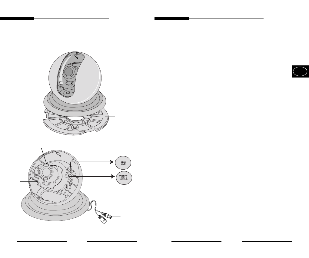
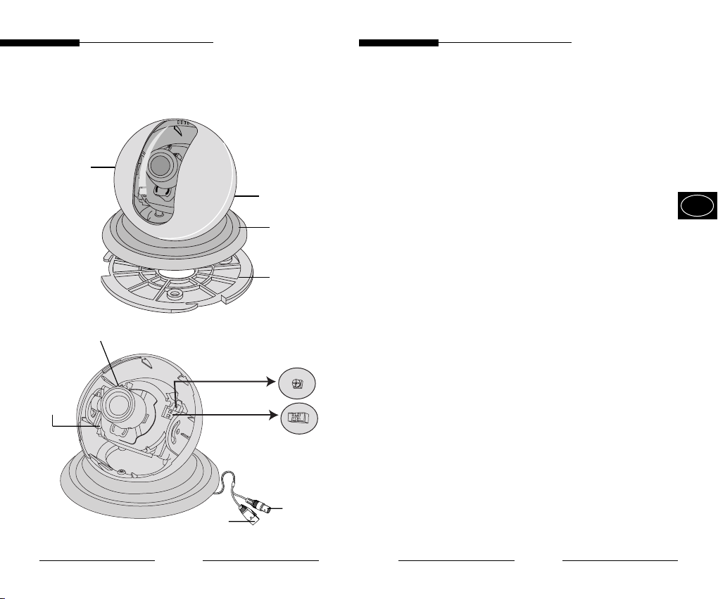
2. Component Name
CASE-TOP
Variable focus
lens
Iris Level Control
PCB
board
Function Switches
Power
cable
CASEBOTTOM
COVERCEILING
BARCKET
Video
cable
3. Function of Each Component
■ CASE-TOP
• The transparent plastic cover that protects the
camera.
Be careful not to make a scratch on it.
■ CASE-BOTTOM
• Combined with the CASE-TOP, supports the
camera.
■ COVER-CEILING
• Combined with the BRACKET, secures the
camera.
■ BRACKET
• Installed to the ceiling or wall with the SCREW,
secures the camera.
■ Variable focus lens
• Variable focus lens installed on the camera.
Please take cautions that any dust or foreign
matter gathers on the front glass surface of the
lens.
■ PCB board
• This part is quite important since it performs
the camera function. Please handle with care.
■ Power cable
• The terminal that is connected to the power
(adaptor) cable. Connect to DC 12V/AC 24V.
■ Video signal output cable
• The cable that sends the video signal.
E
4
5
User Guide
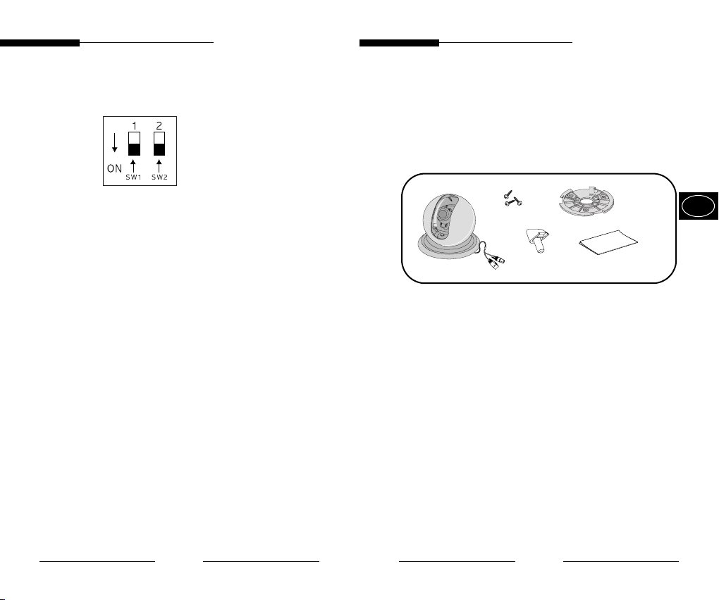
Function Switches
1.L/L 2.FL
SW1
The camera operates in Internal Synchronization
mode when the switch is set to OFF and in Line-Lock
Synchronization mode when the switch is set to ON.
❈ Operating mode is set to lnternal Synchronization
Mode when using the DC12V power supply,
regardless of the L/L switch status.
SW2
Functions to prevent flicker for NTSC systems in areas
with a 50Hz power frequency, and for PAL systems in
areas with a 60Hz power frequency. Flicker occurs
when there is a mismatch between the vertical
synchronizing frequency and lighting control
frequency. When SW2 is set to ON, the electronic
shutter speed is fixed either to 1/100 seconds (NTSC)
or 1/120 seconds (PAL).
Iris Level Control
Use the screwdriver-like adjusting rod to turn the VR
and control the lris level.
4. Installation
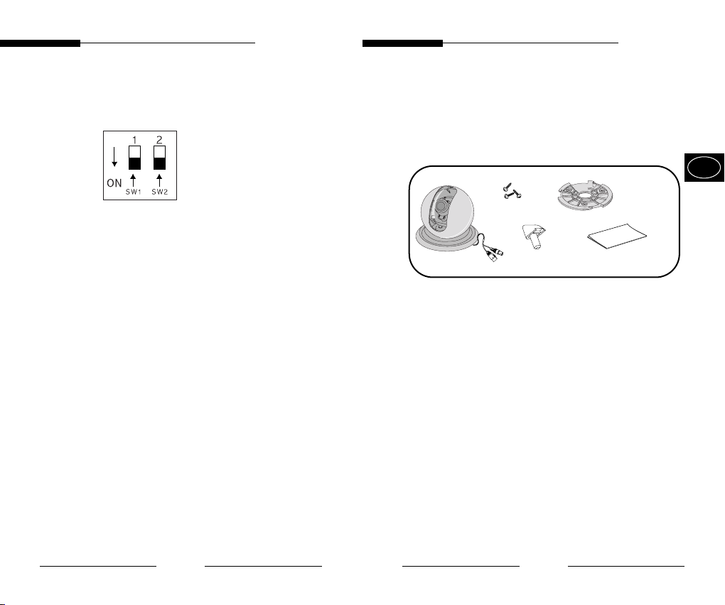
■ Check what is inside the package
• Check to see if the following parts are included in
the purchased package.
tab screw
Camera
■ Notes on installation and usage
1. Users should not disassemble the camera from
the front direction.
2. Always handle the camera with care. Please do
not apply a shock or vibration as much as possible
and take cautions not to cause damage or make a
scratch on the camera due to careless storage.
3. Please do not install the camera with the rainy
place or highly humid areas. And do not operate
the camera in the wet place.
4. Do not clean the camera body with the strong
abrasives or soaps. When the camera becomes
dirty, clean it with the dry rugs. Especially, make
sure to use the dedicated rugs for lens to clean
the dome cover.
5. Please keep the camera at the cool area that is
not exposed to the direct sunlight. If you do, it can
cause bad effects on the product.
STOPPER
PIN
User's guide
User Guide
E
BRACKET
6
7
User Guide
User Guide
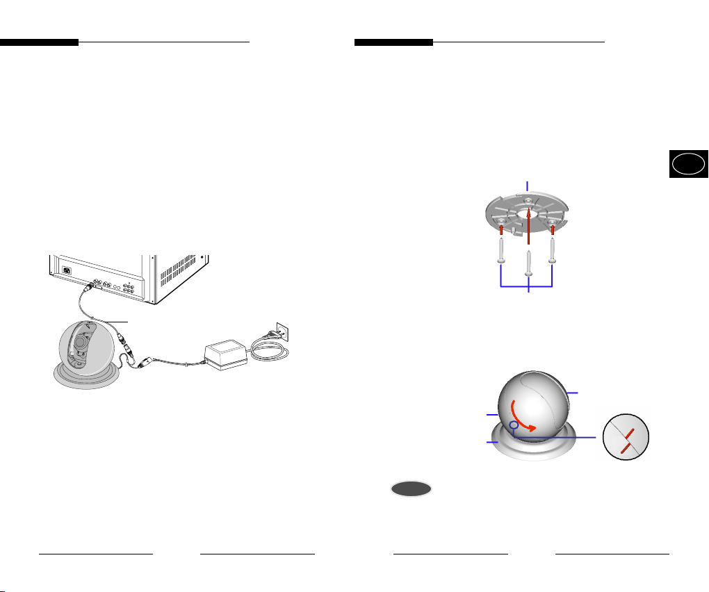
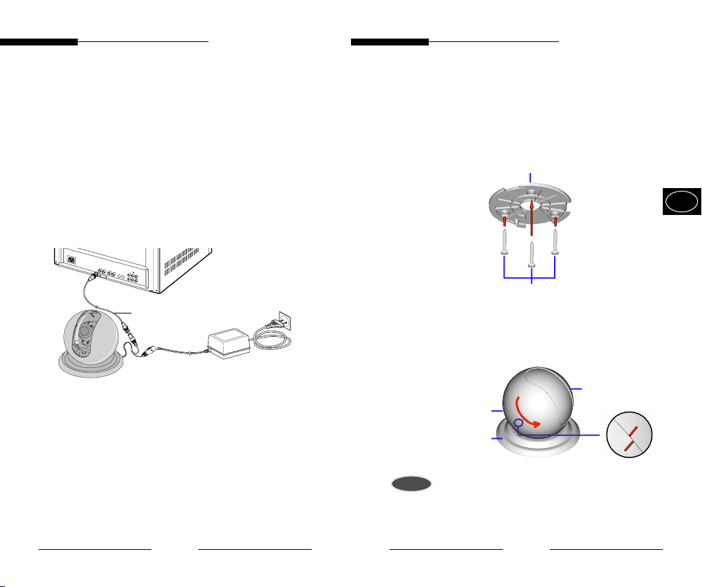
■ Cable connection
1.Connect the BNC cable to the video cable
connector attached on the dome camera,
and connect the remained BNC cable to the
video input terminal of the monitor.
2.Connect the power adaptor at this time.
Connect the DC 12V/AC 24V power cable of
the connector to the power cable connection
that is attached on the dome camera.
Monitor
BNC Cable
■
Installation
1. Select an installation location capable of bearing five
times the weight of the product.
2. Fix the BRACKET to the location desired with the
supplied SCREWs.
BRACKET
FIXING SCREW
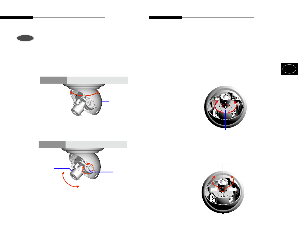
3. Hold the CASE-BOTTOM of the camera with one
hand and use the other hand to rotate the CASE-TOP
approximately 20 degrees in the anti-clockwise
direction to remove it.
CASE-TOP
CASE-BOTTOM
COVER-CEILING
Caution
Make sure to hold the CASE-BOTTOM and not the
COVER-CEILING part when rotating the CASE-TOP.
Otherwise, the internal 360°-Rotation-Preventing system
may get damaged.
E
8
9

User Guide
User Guide
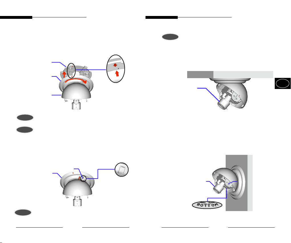
4. Align the arrows on the COVER-CEILING and the
BRACKET to assemble the two parts and then rotate the
COVER-CEILING approximately 25 degrees to fix them
together.
BRACKET
COVER-CEILING
CASE-BOTTOM
Align the arrows on each side when assembling the pieces
Point
Caution
Make sure to hold and rotate the COVER-CEILING and
not the CASE-BOTTOM, otherwise the COVERCEILING may not turn appropriately and the camera will
not be properly assembled.
5. Push the STOPPER-PIN firmly into the COVER-CEILING
HOLE STOPPER-PIN
STOPPER-
COVERCEILING
PIN
Caution
The STOPPER-PIN needs to be properly in place to prevent
the camera body from falling off.
6. Adjusting the horizontal alignment of the camera LENS
BLOCK.
- Leave the lens block position as provided when
installing on a ceiling.
ceiling
LENS-
BLOCK
Installing on a ceiling (Default position)
- Completely unscrew the LENS-BLOCK fixing-screw in
the anti-clockwise direction and rotate the LENSBLOCK 180°. The text - “BOTTOM” - must face
downwards. Fix the LENS-BLOCK by putting the
removed fixing-screw back into the other side.
Wall
LENS-
BLOCK
Fixing-Screw
E
Use a straight screwdriver to lift and pull out the
Point
STOPPER-PIN when dismantling.
10
Installing onto a wall.
11
User Guide
User Guide
Caution
The Lens Block must be rotated when installing onto a wall.
The horizontal and vertical alignments would be inversed if
the camera is installed as provided
7. Rotate the CASE-BOTTOM part of the camera to set
the monitoring direction
ceiling
CASEBOTTOM
8. Unscrew the LENS-BLOCK Fixing-Screw slightly to adjust
the vertical monitoring position.
ceiling
LENS-
BLOCK
Fixing-Screw
9. Adjusting ZOOM and FOCUS.
9-1. Adjusting the ZOOM: Unscrew the ZOOM LEVER
slightly to allow the zoom position to be adjusted
- Zooming in (TELE): Rotate the ZOOM LEVER in a
clockwise direction to obtain a wider angle view.
- Zooming out (WIDE): Rotate the ZOOM LEVER in
an anti-clockwise direction to obtain a narrower
angle view.
ZOOM LEVER
9-2. Adjusting the FOCUS: Unscrew the FOCUS
LEVER and adjust it to achieve best focus on the
screen.
FOCUS LEVER
FAR
NEAR
E
12
13

User Guide
User Guide
9-3. Rotate the LEVERs clockwise when zoom and
focus adjustments are finished to lock the positions.
10. Hold the CASE-BOTTOM part with one hand and then
place the CASE-TOP onto the CASE-BOTTOM,
aligning the lines marked on the sides. Rotate the
CASE-TOP firmly approximately 20 degrees
clockwise to assemble.
CASE-BOTTOM
Point
CASE-TOP
Align the lines marked when assembling the two pieces
5. Specifications
Item Details
Broadcasting system SCC-B5351(G) : NTSC STANDARD
SCC-B5351(G)P : PAL STANDARD
Pick-up device 1/3" SUPER HAD IT CCD
Number of effective SCC-B5351(G) : 768(H) x 484(V)
pixel SCC-B5351(G)P : 752(H) x 582(V)
Synchronization Internal/Linelock
Resolution 480 TV Lines (H)
350 TV Lines (V)
Video output VBS 1.0Vp-p(75 , composite)
S/N ratio 50dB
Min. illumination 0.3Lux
Flickerless
Lens (focal length)
Gamma correction 0.45
Body Color SCC-B5351(P) :
In/out connector
Operating temperature -10~+50°C
Power source
Power consumption 3 W
Size 118(ø) x 100(H)mm
Weight About 250g
On/Off
f=3.4~9mm Auto Iris
Black
SCC-B5351G(P) :
Signal output: BNC, Power input : 2P-Jack
10%,-5%, AC 24V 10%
DC 12V
(NTSC : 60Hz 0.1Hz, PAL :50Hz 0.1Hz)
White
E
14
15
Manuel de l’utilisateur
Manuel de l’utilisateur
L’objectif des précautions de sécurité est d’assurer l’utilisation
correcte de ce produit afin d’éloigner tout risque et tout dégât à la
propriété. Assurez-vous de bien observer toutes les précautions.
Avertissement
Ne pas tenir compte d’un avertissement risque de causer
des blessures graves, voire mortelles.
1. Assurez-vous d’utiliser uniquement l’adaptateur fourni avec le
produit. (L’utilisation d’un adaptateur autre que celui fourni peut
endommager le produit ou causer un incendie ou des décharges
électriques.)
2. Avant de brancher le cordon d’alimentation et les câbles de signal,
vérifiez d’abord les bornes extérieures. Reliez les câbles des
signaux d’alarme à leur borne respective. Branchez l’adaptateur CA
sur la prise CA et l’adaptateur CC sur la prise CC tout en tenant
compte de la bonne polarité. (La connexion incorrecte à la source
d’alimentation peut endommager le produit ou causer un incendie
ou des décharges électriques.)
3. Ne branchez jamais plus d’une caméra sur un seul adaptateur.
(Le dépassement de la capacité de charge risque de générer une
chaleur anormale au point de causer un incendie.)
4. Branchez le cordon d’alimentation sur la prise murale. Assurezvous que la connexion est solidement fixée. (Une mauvaise
connexion peut constituer le risque d’un incendie.)
5. Lorsque vous installez la caméra au mur ou au plafond, assurezvous qu’elle y soit fixée solidement et de faáon sécuritaire. (La
chute de la caméra peut causer des blessures corporelles.)
6. Ne placez jamais d’objets conducteurs (p. ex., un tournevis, des
pièces de monnaie, tout autre objet métallique) ni de contenants
remplis d’eau sur la caméra. (Cela pourrait présenter un risque de
blessures corporelles en raison d’un incendie, d’une décharge
électrique ou de la chute d’un objet.)
7. N’installez pas la caméra dans un emplacement plein de suie, de
poussière ou d’humidité. Cela pourrait causer un incendie ou
provoquer une décharge électrique.
8. Si vous détectez une odeur étrange ou de la fumée qui sort du
produit, débranchez immédiatement le cordon d’alimentation et
contactez le centre de soutien technique. (Une sollicitation continue
de l’appareil dans ces conditions pourrait causer un incendie ou
provoquer des décharges électriques.)
9. Si ce produit cesse de fonctionner correctement, communiquez
avec votre revendeur ou le centre d’entretien dans votre localité. Ne
démontez ni ne modifiez jamais ce produit. (Samsung n’est pas
responsable des problèmes techniques découlant d’une
modification non autorisée ou d’une tentative de réparation.)
10. Lorsque vous nettoyez le produit, veillez à ne pas vaporiser d’eau
directement sur les composants du produit. (Cela pourrait causer un
incendie ou provoquer une décharge électrique.) Nettoyez la
surface au moyen d’un chiffon doux. N’utilisez jamais de détersifs ni
de nettoyants chimiques. Cela pourrait provoquer une décoloration
ou endommager le fini du produit.
Mise en garde
Ne pas tenir compte d’une mise en garde peut entraåner
des blessures cor porelles ou des dégâts à la propriété.
1. Ne laissez pas tomber d’objets sur le produit ni ne soumettez le
produit à de forts coups. Ne placez pas le produit dans un
emplacement où il pourrait subir de fortes vibrations ou des
interférences magnétiques.
2. Ne placez pas le produit dans un emplacement où il fait très chaud
(plus de 50°C/122°F), très froid (moins de ‘10°C/14°¯F) ou très
humide. (Cela pourrait causer un incendie ou provoquer une
décharge électrique.)
3. Évitez un emplacement où le produit est exposé à des rayons
directs du soleil ou à une source de chaleur, telle qu’un radiateur ou
un appareil de chauffage. (Le non-respect de cette consigne
pourrait présenter un risque d’incendie.)
4. Si vous désirez déplacer le produit à la suite de son installation,
assurez-vous de couper le courant avant son déplacement et sa
réinstallation.
5. Installez le produit dans une aire bien ventilée.
6. En cas d’orage, débranchez le cordon électrique de la prise murale.
(Le non-respect de cette consigne pourrait provoquer un incendie
ou endommager le produit.)
7. Évitez de diriger l’appareil photo directement en direction d’objets
très brillants, tels qur le soleil, cela risque d’endommager le capteur
d’ image CCD.
F

Contenu
Manuel de l’utilisateur
1.
Vue d’ensemble
Manuel de l’utilisateur
1.
Vue d’ensemble
2.
Description
3.
Fonction de chaque composant
4. Installation
5.
Spécifications
......................................................
................................................................
.....................................................................
........................................................
.........................
15
3
4
5
7
Les dômes couleur sont des caméras de surveillance
avec un CCD intégré offrant les meilleures fonctions
de surveillance en connexion avec le système CCTV.
■ Nombre de pixels CCD
• SCC-B5351(G) : 410,000 pixels
• SCC-B5351(G)P : 470,000 pixels
■ Alimentation
• CC 12V/ CA 24V
■
Fonctions automatiques et fonctions spéciales
• ATW
• BLC
• AGC
• ALC
• SP(Sans papillotement) Activer/Désactiver
• Verrouillage de ligne Activer/Désactiver
❈
Le mode Interne offre une meilleure qualité d’image que
le mode Verrouillage de fin de ligne.
F
2
3
2.
Description
HAUT DU
BOÎTIER
Objectif zoom
PCB
planche
Manuel de l’utilisateur Manuel de l’utilisateur
3.
Fonction de chaque
composant
■ HAUT DU BOÎTIER
• Le couvercle transparent en plastique
protégeant la caméra.
Faites attention à ne pas le griffer.
BAS DU
BOÎTIER
Commande du niveau
du diaphragme
Sélecteurs de
fonction
Câble
électrique
CACHE
PLAFOND
SUPPORT
Câble vidéo
■ BAS DU BOÎTIER
• Combiné avec le HAUT DU BOÎTIER,
supporte la caméra.
■ CACHE PLAFOND
• Combiné avec le SUPPORT, permet de
sécuriser la caméra.
■ SUPPORT
• Installé au plafond ou au mur à l’aide des VIS,
permet de sécuriser la caméra.
■ Objectif zoom fixe
• L’objectif zoom fixe installé sur la caméra.
Veuillez faire attention à ce qu’aucune
poussière ou matière venant de l’extérieur ne
s’accumule sur la surface avant de l’objectif.
■ Panneau PCB
• C’est une partie très importante car elle
exécute les fonctions de la caméra. Veuillez
manipuler ce panneau avec précaution.
■ Câble d’alimentation
• Le terminal connecté au câble d’alimentation
(d’adaptateur). Connectez à CC 12V/CA 24V.
■ Câble de production de signal vidéo
• Le câble qui envoie le signal vidéo.
F
4
5
Manuel de l’utilisateur
■
Sélecteurs de fonction
1.L/L 2.FL
SW1
La caméra fonctionne en mode Synchronisation
interne lorsque l’interrupteur est placé sur
DÉSACTIVER et en mode Synchronisation
verrouillage de ligne lorsque l’interrupteur est placé sur
ACTIVER.
❊
Le mode de fonctionnement est fixé sur le mode
Synchronisation interne lorsque vous utilisez une
alimentation CC12V indifféremment de l’état de
l’interrupteur L/L.
SW2
Ce bouton est utilisé pour éviter la vacillation de
l’écran lorsque le système NTSC est utilisé avec une
alimentation 50HZ ou lorsque le système PAL est
utilisé avec une alimentation 60HZ. Ceci permet
d’empêcher les secousses à l’écran dues à la
discordance entre la fréquence de synchronisation
verticale et la fréquence de vacillation de l’éclairage.
Lorsque ce bouton est positionné sur ON, l’obturateur
électrique est fixé sur 1/100sec (NTSC) ou 1/120 sec
(PAL).
■
Commande du niveau du diaphragme
VR pour le réglage de la luminosité du signal vidéo.
Utilisez une tige-rallonge de type tournevis pour
tourner le VR et contrôler le niveau du diaphragme.
6
Manuel de l’utilisateur
4.
Installation
■
Vérification du contenu de l’emballage
• Vérifiez que les éléments suivants sont inclus
dans l’emballage.
SUPPORT
Vis
Caméra
■ Notes sur l’installation et l’utilisation
1. L’utilisateur ne doit pas démonter la partie avant de la
caméra.
2. Manipulez toujours la caméra avec précaution.
Evitez tout choc ou vibration et faites attention à ce que
la caméra ne soit pas endommagée ou griffée lors du
stockage.
3. Evitez d’installer la caméra dans un endroit exposé à la
pluie ou à une humidité élevée.
Ne faites pas fonctionner la caméra dans un endroit
humide.
4. N’utilisez pas d’abrasif ou de savon pour nettoyer la
caméra. Lors du nettoyage de la caméra, utilisez un
chiffon sec. En particulier, le couvercle en dôme doit être
nettoyé avec un chiffon spécifique, conçu pour l’objectif.
5. Conservez la caméra dans un endroit frais en évitant le
rayonnement direct du soleil, afin d’éviter tout mauvais
effet sur l’appareil.
BROCHE
D’ARRÊT
Manuel de
l’utilisateur
7
F
Manuel de l’utilisateur
Manuel de l’utilisateur
■ Connexion du câble
1. Connectez le câble BNC au câble vidéo fixé sur la
caméra en dôme et connectez l’autre extrémité du
câble BNC à l’entrée vidéo du moniteur.
2. Connectez ensuite l’adaptateur d’alimentation.
Connectez le câble d’alimentation CC 12V/CA 24V
de l’adaptateur au câble d’alimentation fixé sur la
caméra en dôme.
Moniteur
BNC Câble
■ Installation
1. Sélectionnez un emplacement capable de supporter 5
fois le poids du produit.
2. Fixez le SUPPORT à l’endroit choisi à l’aide des VIS
fournies.
SUPPORT
FIXATION DES VIS
3. Tenez le BAS DU BOÎTIER de la caméra avec une
main et avec l’autre main, tournez le HAUT DU
BOÎTIER d’environ 20 degrés dans le sens inverse
des aiguilles d’une montre pour démonter.
CASE-TOP
CASE-BOTTOM
(BAS DU BOÎTIER)
COVER-CEILING
(CACHE PLAFOND)
Avertissement
• Assurez-vous de tenir le BAS DU BOÎTIER et non pas le
CACHE PLAFOND lorsque vous tournez le HAUT DU
BOÎTIER. Dans le cas contraire, le système interne de
prévention de rotation à 360° risque d’être endommagé.
(HAUT DU BOÎTIER )
F
8
9
Manuel de l’utilisateur
Manuel de l’utilisateur
4. Alignez les flèches sur le CACHE PLAFOND et le
SUPPORT pour assembler les deux parties et tournez
ensuite le CACHE PLAFOND d’environ 25 degrés pour
les fixer ensemble.
BRACKET(SUPPORT)
COVER-CEILING
(CACHE PLAFOND)
CASE-BOTTOM
(BAS DU BOÎTIER)
• Alignez les flèches de chaque côté lors de
Point
Avertissement
l’assemblage des pièces
• Assurez-vous de tenir et tourner le CACHE PLAFOND
et non pas le BAS DU BOÎTIER sinon le CACHE
PLAFOND risque de ne pas tourner correctement et la
caméra ne serait pas bien assemblée.
5. Placez la BROCHE D’ARRÊT dans le TROU du
CACHE PLAFOND.
STOPPER-PIN
(BROCHE D’ARRÊT)
COVER-CEILING
(CACHE PLAFOND)
Avertissement
• La BROCHE D’ARRÊT doit être placée correctement afin
d’éviter la chute du corps de la caméra.
6. Réglage de l’alignement horizontal du BLOC
OBJECTIF de la caméra.
- Laissez la position du bloc objectif telle que fournie en
cas d’installation au plafond.
LENS-BLOCK
(BLOC OBJECTIF)
Installation au plafond (Position par défaut)
- Dévissez entièrement la vis de fixation du BLOC
OBJECTIF dans le sens contraire des aiguilles d’une
montre et tournez le BLOC OBJECTIF de 180°.
L’inscription, BAS, doit être dirigée vers le bas. Fixez
le BLOC OBJECTIF en plaçant la vis de fixation que
vous avez retirée de l’autre côté.
LENS-BLOCK
(BLOC OBJECTIF)
plafond
F
Paroi latérale
Vis de fixation
• Utilisez un tournevis droit pour soulever et sortir la
Point
BROCHE D’ARRÊT lors du démontage.
10
Installation sur une paroi latérale.
11
 Loading...