


SCC-B5344
SCC-B5345
Digital Color Dome Camera
operating instructions
imagine the possibilities
Thank you for purchasing this Samsung product.
To receive more complete service, please register
your product at
www.samsung.com/global/register
ENG RUS POL

3
Safety Precautions
CAUTION
RISK OF ELECTRIC
SHOCK DO NOT OPEN
CAUTION: TO REDUCE THE RISK OF
ELECTRIC SHOCK, DO NOT REMOVE REAR
COVER. NO USER SERVICEABLE PARTS
INSIDE. REFER TO QUALIFIED SERVICE
PERSONNEL.
This symbol indicates high voltage
is present inside. It is dangerous to
make any kind of contact with any
inside part of this product.
This symbol alerts you that important
literature concerning operation and
maintenance has been included with
this product.
To prevent damage which may result in re
or electric shock hazard, do not expose this
appliance to rain or moisture.
WARNING
1. Be sure to use only the standard adapter
that is specied in the specication
sheet. Using any other adapter could
cause re, electrical shock, or damage
to the product
2. Incorrectly connecting the power
supply or replacing battery may cause
explosion, re, electric shock, or damage
to the product.
2
3.
Do not connect multiple cameras to a single
adapter. Exceeding the capacity may cause
abnormal heat generation or re.
4. Securely plug the power cord into the
power receptacle. Insecure connection
may cause re.
5. When installing the camera, fasten it
securely and rmly. A falling camera may
cause personal injury.
6. Do not place conductive objects (e.g.
screwdrivers, coins, metal things, etc.) or
containers lled with water on top of the
camera. Doing so may cause personal
injury due to re, electric shock, or falling
objects.
7. Do not install the unit in humid, dusty, or
sooty locations. Doing so may cause re
or electric shock.
8. If any unusual smells or smoke come
from the unit, stop using the product. In
such case, immediately disconnect the
power source and contact the service
center. Continued use in such a condition
may cause re or electric shock.

ENG
3
9. If this product fails to operate normally,
contact the nearest service center. Never
disassemble or modify this product
in any way. (SAMSUNG is not liable
for problems caused by unauthorized
modications or attempted repair.)
10. When cleaning, do not spray water
directly onto parts of the product. Doing
so may cause re or electric shock.
CAUTION
1. Do not drop objects on the product or
apply strong shock to it. Keep away from
a location subject to excessive vibration
or magnetic interference.
2. If you want to relocate the already
installed product, be sure to turn off the
power and then move or reinstall it.
3. Remove the power plug from the
outlet when then there is a lightning.
Neglecting to do so may cause re or
damage to the product.
4. Keep out of direct sunlight and heat
radiation sources. It may cause re.
5. Install it in a place with good ventilation.
6. Avoid aiming the camera directly towards
extremely bright objects such as sun,
as this may damage the CCD image
sensor.
7. Apparatus shall not be exposed to
dripping or splashing and no objects
lled with liquids, such as vases, shall be
placed on the apparatus.
8. The Mains plug is used as a disconnect
device and shall stay readily operable at
any time
FCC Statement
This device complies with part 15 of the FCC
Rules. Operation is subject to the following
two conditions:
1) This device may not cause harmful
interference, and
2) This device must accept any interference
received including interference that may
cause undesired operation.
Note
This equipment has been tested and found to
comply with the limits for a Class A digital device,
pursuant to part 15 of FCC Rules. These limits
are designed to provide reasonable protection
against harmful interference when the equipment
is operated in a commercial environment. This
equipment generates, uses, and can radiate
radio frequency energy and, if not installed
and used in accordance with the instruction
manual, may cause harmful interference to radio
communications. Operation of this equipment
in a residential area is likely to cause harmful
interference in which case the user will be
required to correct the interference at his own
expense.

5
Important Safety Instructions
1. Read these instructions.
2. Keep these instructions.
3. Heed all warnings.
4. Follow all instructions.
5. Do not use this apparatus near water.
6. Clean only with dry cloth.
7. Do not block any ventilation openings.
Install in accordance with the
manufacturer’s instructions.
8. Do not install near any heat sources
such as radiators, heat registers, or
other apparatus (including ampliers)
that produce heat.
9. Do not defeat the safety purpose of
the polarized or grounding-type plug.
A polarized plug has two blades with
one wider than the other. A grounding
type plug has two blades and a third
grounding prong. The wide blade or the
third prong is provided for your safety.
If the provided plug does not t into
your outlet, consult an electrician for
replacement of the obsolete outlet.
10. Protect the power cord from being
walked on or pinched particularly at
plugs, convenience receptacles, and the
point where they exit from the apparatus.
11. Only use attachments/accessories
specied by the manufacturer.
12. Use only with cart, stand, tripod, bracket,
or table specied by the manufacturer, or
sold with the apparatus.
4
13. Unplug this apparatus. When a cart is
used, use caution when moving the
cart/apparatus combination to avoid
injury from tip-over.
14. Refer all servicing to qualied service
personnel. Servicing is required when
the apparatus has been damaged in any
way, such as power-supply cord or plug
is damaged, liquid has been spilled or
objects have fallen into the apparatus,
the apparatus has been exposed to rain
or moisture, does not operate normally,
or been dropped.

ENG
5
Contents
Overview ......................................................................................6
About this guide ............................................................................6
Product overview ...........................................................................6
Main features .................................................................................6
Components ...................................................................................6
Checking components in the package .......................................6
Components of your camera ...................................................... 7
Installation ..................................................................................8
Setting switches ............................................................................8
Setting function switches ............................................................8
Connecting cables and changing the settings .........................10
Installing camera .........................................................................11
Before installation ..................................................................... 11
Installation procedure ............................................................... 11
Adjusting the camera direction .................................................. 12
Appendix A: Specications for NTSC Standard ........... 14
Appendix B: Specications for PAL Standard .............. 15
7
Overview
About this guide
❚
This user guide includes basic instructions for
the product. It is recommended that all users
read this guide before use.
This guide is divided as follows:
Chapter 1, “Overview,” introduces the user guide
and product related information. (This chapter)
Chapter 2, “Installation,” explains how to set and
install the product.
Appendix, “Specications,” provides the
specications of the product.
Product overview
❚
This is the high resolution (540 TV lines) dome
camera equipped with a Vari-focal lens, which
has no dynamic delay when implementing
motion pictures, and provides the features
such as digital noise reduction (DNR) by real-
time CCD defect compensation, low speed
shutter (LSS: Auto x128) to implement clear
picture quality, Day/Night color compensation,
and the like.
Main features
❚
Power: DC 12V/AC 24V
Special functions
Line lock (LL) control
Auto white balancing
Horizontal/vertical image reversing
Flickerless control
Low shutter speed control
Backlight compensation control
Automatic switching between color and black
& white modes
Equipped with vari-focal lens
Auto Iris function
Digital noise reduction (DNR)
Dynamic CCD defect compensation
6
Components
❚
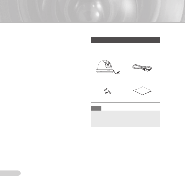
Checking components in the package
Please check your camera and accessories
are included in the package. Those
components are as shown below:
Camera Test Monitor Cable
Tab screw User’s Guide
Note
The test monitor cable is used to test the camera
by connecting to a portable display. If you really
want to connect the camera to a monitoring
display, use the BNC cable.
ENG
7
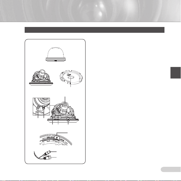
Components of your camera
Your camera has the following components:
1
2
3
4
Lens
6
5
7 8 9
0
!
Video connector
Power connector
1
2
3
4
5
6
7
8
9
0
!
Cover dome
Main body: Includes a lens, a switch board, a PCB
board, screws, and such.
Mount bracket
is xed using three long tab screws provided in the
package.
Cable Stopper: If drawing the cable from a hole in
the ceiling, remove this stopper and pass the cable
through the opening to connect.
Zoom lever
adjusted and xed.
Focus lever
rotating it left or right. Rotate it clockwise for xing.
Tiltxingscrew
lens can be adjusted and xed.
Switch board
such as function switches and phase-control switches.
The board has eight function switches in the middle
and two phase-control buttons on each side of the
function switch area.
Installation Guide Mark: This mark must be aligned
with the marking on the bracket when attaching the
camera to the bracket.
Lock releaser
body in UNLOCK direction when you want to remove
the Mount bracket from the Main body or to remove
the installed camera from the Mount bracket.
Cable
and Power connector to power adapter.
: Covers the main body for protection.
: Used as a ceiling or wall xture. It
: Using this lever, the lens zoom can be
: The lens focus can be adjusted by
: Using this screw, the slope of the
: Includes two kinds of control switches
: Push it outward and rotate the main
: Connect the Video connector to BNC cable
9
Installation
Setting switches
❚
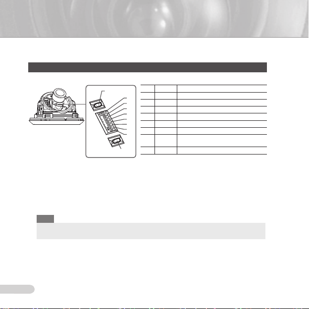
Setting function switches
To set the available functions on your camera, adjust eight switches as shown below:
DEC
1. Switch 1 (LL): When this switch is set to OFF, the camera operates in the internal
synchronization mode, while when it is set to ON, the camera operates in the line lock mode.
In the internal synchronization mode, the camera always uses an inside crystal oscillator for
synchronization. However if multiple cameras are connected to a sequential switcher, picture
rolling or ickering may occur when switching from one camera to another. In this case, you
can set this switch to ON to solve this problem.
The line lock mode allows the camera to use the phase of the AC power as the
synchronization reference. In this mode, you can use the phase control buttons(INC/DEC).
Note
When you are using the DC 12V power, set this switch to OFF. The line lock feature will not normally
operate even when the switch is set to ON.
Set the LL switch to ON while the AC power is connected. If any picture roll happens, you have
to adjust the phase using the phase-control buttons. Press the INC or DEC button to increase or
decrease the phase by one degree.
No Name Brief description
1 LL Line lock ON/OFF
8
2 LSS Sens-up or Low speed shutter ON/OFF
7
6
3 H-REV Horizontal reverse ON/OFF
5
4 V-REV Vertical reverse ON/OFF
4
5 BLC Backlight compensation ON/OFF
3
2
6 FL Flickerless ON/OFF
1
7 D/N
8 AWB Automatic white balance ON/OFF
INC
Automatic switching between color and
black & white ON/OFF
8

ENG
9
2. Switch 2 (LSS): This sens-up mode accumulates the image elds in memory to reduce
noise but increase the brightness and contrast rate. When this switch is set to ON, the
camera automatically switches to a maximum of 128 times of image acquisition speed to
implement a clear picture for darker image.
3. Switch 3 (H-REV)
If you want to monitor your site using a mirror, you can use this feature to see the right
image.
4. Switch 4 (V-REV)
If your camera reluctantly displays the vertically reversed image, you can use this feature to
see the right image.
5. Switch 5 (BLC)
camera faces any excessive light such as sunlight and uorescent light. When it is set to
OFF, the subject with excessive light is not clearly shown.
6. Switch 6 (FL)
NTSC) or 1/120 sec (for PAL) to prevent screen from ickering by the disaccordance
between vertical synchronous frequency (50Hz for NTSC, 60Hz for PAL) and on-and-off
frequency of a light.
7. Switch 7 (D/N)
color and B&W according to the brightness of the vicinity.
8. Switch 8 (AWB)
camera operates in ATW mode, and in case of OFF, this camera operates in AWC mode.
ATW (Auto Tracking White Balance): The color temperature is automatically adjusted according to the
environmental change. (Approx. 2000°K to 11,000°K)
AWC (Auto White Balance Control): It stores the color temperature just when the switch is changed to
OFF. Accordingly color temperatures are adjusted by the stored value.
Caution
-. The IRIS setting range for the camera is approximately 80 to 120 IRE. It means the camera does not
provide the IRIS full open/close feature but the restricted variation range.
-. Use the camera after setting to the proper level (80 IRE or above) because the IRIS hunting may
occur when the level is 75 IRE or below.
: When this switch is set to ON, the camera image is reversed horizontally.
: When this switch is set to ON, the camera image is reversed vertically.
: When this switch is set to ON, you can view a clear image even though the
: When this switch is set to ON, the shutter speed is xed to 1/100 sec (for
: When this switch is set to ON, the camera automatically switches between
: This switch adjusts white balancing. When this switch is set to ON, this
11
Connecting cables and changing the settings
❚
Before installing your camera, you have to adjust the lens focus, zoom, and switch settings.
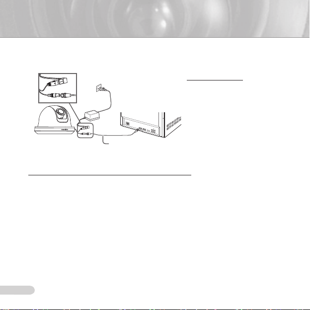
To connect cables
1. Connect the BNC cable
to the Video connector
attached on your camera.
Connect the BNC cable
Monitor
BNC Cable
2.
to the Video Input on a
monitor.
Connect the power adapter
3.
to the Power connector
attached on your camera.
When the monitor is turned
on, the camera image
appears.
To adjust the lens focus, zoom, and function settings
1. Remove the Cover dome and Inner cover. For more details about the removing procedures,
see “Installation procedure,” in the Installing camera section on the next page.
Adjust the focus, zoom, and function settings of your camera using the Focus lever, Zoom
2.
lever, and Switch board while you are viewing the image on the screen.
If you want to x the adjusted focus and zoom, screw up the levers.
3.
10
ENG
11
Installing camera
❚
Before installation
Before installing your camera, you have to read the following cautions:
You have to check whether the location (ceiling or wall) can bear ve times the weight of your camera.
Don’t let the cable to be caught in improper place or the electric line cover to be damaged. Otherwise it
may cause a breakdown or re.
When installing your camera, don’t allow any person to approach the installation site. If you have any
valuable things under the place, move them away.
Partial blind spot can occur at tilt angles of less than 20°, depending on the lens conguration.
Installation procedure
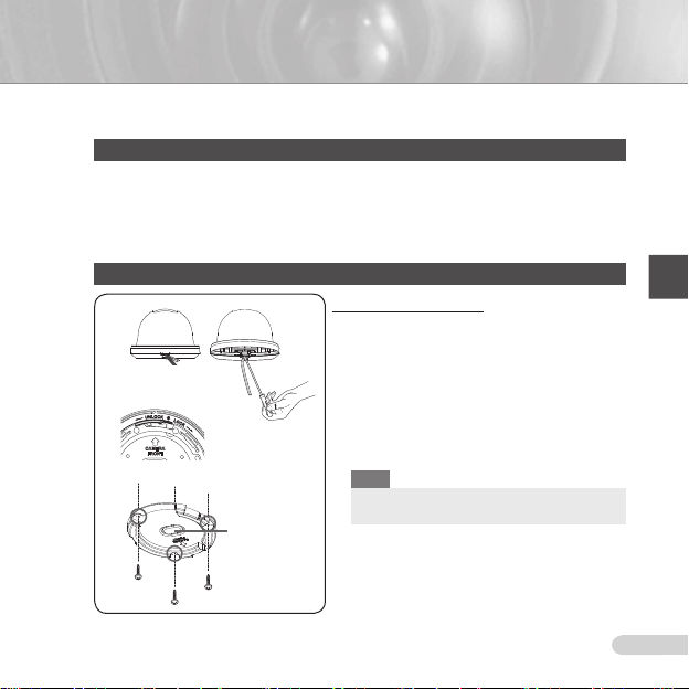
1
2
3
Ceiling mount
opener
To install your camera
Pry up the outer casing with a at-head screwdriver
1
to remove the protective cover from the Main body of
the camera.
Remove the Mount bracket from the Main body by
2
rotating the Main body in the UNLOCK direction while
pushing the Lock releaser outward. If it is not easily
done, rotate the Mount bracket in the LOCK direction
while holding small holes on the Mount bracket.
Fix the Mount bracket to the location (ceiling or wall)
3
with supplied three screws.
Note
The CAMERA FRONT sign on the Mount bracket
should face the camera monitoring area.

13
If a hole has been drilled on the bracket installation surface for cable access, press down to remove
4
the Cable Stopper and then draw the cable in. If connecting through the side of the camera, use the
empty space opposite to the side marked CAMERA FRONT.
Now attach the Main body to the Mount bracket by rotating it in the LOCK direction after aligning
5
the Groove mark on the Main body with the wide groove around the CAMERA FRONT inlay.
Adjust the camera direction. For more details on the direction control, see “Adjusting the camera
6
direction,” on the same page. When required to adjust the zoom and focus for your camera, see
“Connecting cables and changing the settings,” on page 10.
Attach the Inner cover to the Main body by pressing it until a “click” sound is heard after aligning
7
two screw holes on the Wing lockers of the Inner cover with two screw holes on the Main body’s
left and right sides.
Finally attach the Cover dome to the Main body by pressing it until a “click” sound is heard after
8
aligning the bump inside the Cover dome with the Groove mark on the Main body.
Adjusting the camera direction
❚
When the camera is xed on the ceiling, you can adjust
the camera viewing angle. You can rotate your camera
leftward or rightward (Panning), and can change the slope
of your camera upward or downward (Tilting).
In case of panning, the rotation limit of your camera is
set to 355 degree (100 degree clockwise and 255 degree
counterclockwise). The rotation is stopped by the Stopper
inside of the camera. For panning control, rst unfasten
two screws located on the bottom and rotate in the
direction you want, and then fasten them to x the camera.
Tilt can be adjusted between 0° to 90°; however, tilt
angles of less than 20° may result in a partial blind spot,
depending on your lens conguration. To x the location
after adjusting the tilting angle, use the Tiltxingscrews.
To adjust the focus and zoom of your camera, use the Zoom lever and Focus lever.
When you install the camera on the inclined ceiling or wall, you can rotate the camera lens
to see a correct direction image.
Tilting
Panning
Lens rotation
12
ENG
13
SCC-B534X
15
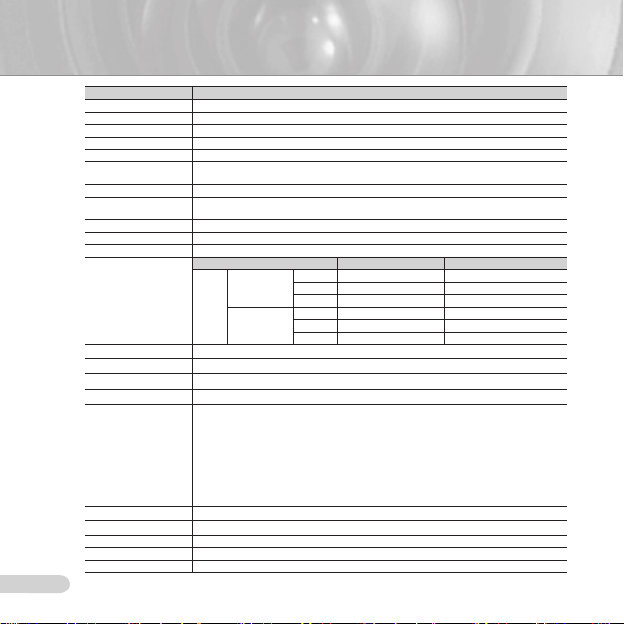
Appendix A: Specications for NTSC Standard
Item Details
Product type CCTV color dome camera
Power input AC 24V ± 10% (60Hz ± 0.3 Hz), DC 12V +10%/-5%
Broadcast type NTSC Standard System (525 Lines, 60 Fields)
Power consumption Approx. 1.7W
Image device 1/3 inch IT Type Super-HAD CCD
Pixels
Scanning mode 525 Lines, 2:1 Interlace
Scanning line frequency
Synchronization mode INT/Line Lock (Adjusting the phase using INC/DEC button)
Horizontal resolution 540 TV Lines
S/N Ratio Approx. 50dB
Min. object illumination
Signal output
Lens Auto Iris (DC) / Focal length: 2.9 ~ 10.0mm / Aperture ratio: 1.2
PAN function Range: 0 to 355° (100 degree clockwise and 255 degree counterclockwise)
TILT function Range: 0 to 90°
Controls
Product color SCC-B534xN : White
Operation temperature -10°C to +50°C
Operation humidity Up to 90%
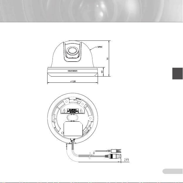
Size 128(Ø) x 91(H)mm
Weight 327g
14
Total: 811(H) x 508(V), 410,000 pixels
Effective: 768(H) x 494(V), 380,000 pixels
Horizontal: 15.734Hz(INT)/15.750Hz(LL)
Vertical: 59.94Hz(INT)/60Hz(LL)
SCC-B5345 (Color/BW) SCC-B5344 (Color/BW)
Sens-up Off
F1.2
Sens-up x128
COMPOSITE Video(1.0 Vp-p, 75ohm, BNC), Test Monitor OUT(1.0 Vp-p, 75ohm, Harness cable)
Line Lock (LL)
Sens-Up; Low Speed Shutter(LSS)
Horizontal Reverse (H-REV)
Vertical Reverse (V-REV)
Backlight compensation (BLC)
Flickerless (FL)
Switching between color and B&W modes (D/N)
Auto white balancing (AWB)
Digital noise reduction (DNR)
Dynamic CCD defect compensation
50IRE 0.4/0.04Lux 0.4/0.4Lux
30IRE 0.24/0.024Lux 0.24/0.24Lux
15IRE 0.12/0.012Lux 0.12/0.12Lux
50IRE 0.0031/0.00031Lux 0.0031/0.0031Lux
30IRE 0,0019/0.00019Lux 0.0019/0.0019Lux
15IRE 0.0009/0.00009Lux 0.0009/0.0009Lux
ENG
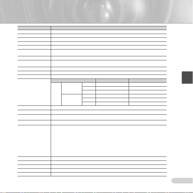
15
Item Details
Product type CCTV color dome camera
Power input AC 24V ± 10% (50Hz ± 0.3 Hz), DC 12V +10%/-5%
Broadcast type PAL Standard System (625 Lines, 50 Fields)
Power consumption Approx. 1.7W
Image device 1/3 inch IT Type Super-HAD CCD
Pixels
Scanning mode 625 Lines, 2:1 Interlace
Scanning line frequency
Synchronization mode INT/Line Lock (Adjusting the phase using INC/DEC button)
Horizontal resolution 540 TV Lines
S/N Ratio Approx. 50dB
Min. object illumination
Signal output
Lens Auto Iris (DC) / Focal length: 2.9 ~ 10.0mm / Aperture ratio: 1.2
PAN function Range: 0 to 355° (100 degree clockwise and 255 degree counterclockwise)
TILT function Range: 0 to 90°
Controls
Product color SCC-B534xP : White
Operation temperature -10°C to +50°C
Operation humidity Up to 90%
Size 128(Ø) x 91(H)mm
Weight 327g
Total: 795(H) x 596(V), 470,000 pixels
Effective: 752(H) x 582(V), 440,000 pixels
Horizontal: 15.625Hz(INT)/15.625Hz(LL)
Vertical: 50Hz(INT)/50Hz(LL)
SCC-B5345 (Color/BW) SCC-B5344 (Color/BW)
Sens-up Off
F1.2
Sens-up x128
COMPOSITE Video(1.0 Vp-p, 75ohm, BNC), Test Monitor OUT(1.0 Vp-p, 75ohm, Harness cable)
Line Lock (LL)
Sens-Up; Low Speed Shutter(LSS)
Horizontal Reverse (H-REV)
Vertical Reverse (V-REV)
Backlight compensation (BLC)
Flickerless (FL)
Switching between color and B&W modes (D/N)
Auto white balancing (AWB)
Digital noise reduction (DNR)
Dynamic CCD defect compensation
50IRE 0.4/0.04Lux 0.4/0.4Lux
30IRE 0.24/0.024Lux 0.24/0.24Lux
15IRE 0.12/0.012Lux 0.12/0.12Lux
50IRE 0.0031/0.00031Lux 0.0031/0.0031Lux
30IRE 0,0019/0.00019Lux 0.0019/0.0019Lux
15IRE 0.0009/0.00009Lux 0.0009/0.0009Lux
Correct Disposal of This Product
(Waste Electrical & Electronic Equipment)
(Applicable in the European Union and other European countries with separate
collection systems)
This marking shown on the product or its literature, indicates that it should
not be disposed with other household wastes at the end of its working life. To
prevent possible harm to the environment or human health from uncontrolled
waste disposal, please separate this from other types of wastes and recycle it
responsibly to promote the sustainable reuse of material resources.
Household users should contact either the retailer where they purchased this
product, or their local government ofce, for details of where and how they can
take this item for environmentally safe recycling.
Business users should contact their supplier and check the terms and conditions
of the purchase contract. This product should not be mixed with other commercial
wastes for disposal.

SCC-B5344
SCC-B5345
Цифровая цветная купольная видеокамера
Руководство по эксплуатации
Удивительные возможности
Благодарим вас за приобретение данного устройства Samsung.
Для получения наилучшего обслуживания зарегистрируйте
свое устройство по адресу:
www.samsung.com/global/register
RUS

3
ТЕХНИКА БЕЗОПАСНОСТИ
ВНИМАНИЕ
ОПАСНОСТЬ ПОРАЖЕНИЯ
ЭЛЕКТРИЧЕСКИМ ТОКОМ. НЕ ОТКРЫВАТЬ
ВНИМАНИЕ: ВО ИЗБЕЖАНИЕ ПОРАЖЕНИЯ ЭЛЕКТРИЧЕСКИМ ТОКОМ, НЕ
СНИМАЙТЕ ЗАДНЮЮ КРЫШКУ. ВНУТРИ НЕТ ДЕТАЛЕЙ, ОБСЛУЖИВАЕМЫХ
ПОЛЬЗОВАТЕЛЕМ. ДЛЯ ТЕХНИЧЕСКОГО ОБСЛУЖИВАНИЯ ОБРАЩАЙТЕСЬ
К КВАЛИФИЦИРОВАННОМУ СПЕЦИАЛИСТУ.
Этот символ обозначает, что
внутри устройства имеется опасное
напряжение, которое может привести
к поражению электрическим током.
Этот символ указывает, что
в документации на изделие
имеется важная инструкция по его
использованию или обслуживанию.
ПРЕДУПРЕЖДЕНИЕ
• Во избежание повреждений, следствием которых может быть
пожар или поражение электрическим током, не допускайте
попадания данного изделия под дождь или в условия высокой
влажности.
ПРЕДУПРЕЖДЕНИЕ
1. Пользуйтесь только стандартным блоком питания, который
указан в листе спецификаций. Использование любого
другого блока питания может привести к пожару, поражению
электрическим током или к повреждению изделия.
2. Неправильное подключение блока питания или замена
батареи может привести к взрыву, пожару, поражению
электрическим током или к повреждению изделия.
3. Не подключайте несколько видеокамер к одному блоку
питания. Превышение нагрузочной способности блока питания
может привести к его перегреву или к пожару.
4. Надежно вставьте вилку сетевого шнура в розетку сети
переменного тока. Ненадежное подключение может привести
к пожару.
2
5. При установке видеокамеры закрепите ее прочно и надежно.
Падение видеокамеры может привести к травме.
6. Не кладите сверху на видеокамеру токопроводящие предметы
(например, отвертки, монеты и другие металлические
предметы) и не ставьте на нее наполненные водой сосуды.
Невыполнение этих требований может привести к пожару,
поражению электрическим током или к травмам в результате
падения этих предметов.
7. Не устанавливайте изделие во влажных, запыленных
или покрытых копотью помещениях. Невыполнение этого
требования может привести к пожару или к поражению
электрическим током.
8. Если вы почувствуете необычный запах или обнаружите дым,
выходящий из изделия, прекратите эксплуатацию. В этом
случае следует немедленно отсоединить изделие от источника
питания и связаться с сервисным центром. Продолжение
эксплуатации изделия в таком состоянии может привести к
пожару или к поражению электрическим током.
9. При обнаружении неисправности в изделии свяжитесь с
ближайшим сервисным центром. Никогда не разбирайте
данное изделие и не вносите изменений в его конструкцию.
(Компания SAMSUNG не несет ответственности за проблемы,
возникшие в результате внесения изменений в конструкцию
изделия или попыток самостоятельно выполнить ремонт
изделия).
10. При чистке изделия не разбрызгивайте на него воду. Это
может привести к пожару или к поражению электрическим
током.
ВНИМАНИЕ

3
RUS
1. Не роняйте на изделие никакие предметы и не
ударяйте по нему. Не устанавливайте изделие в
местах с сильной вибрацией или вблизи источников
магнитного поля.
2. Не устанавливайте изделие в помещениях с
высокой температурой (выше 50°С), пониженной
температурой (ниже -10°С) или высокой
влажностью. Это может привести к возгоранию или
поражению электрическим током.
3. Если вы хотите переместить ранее установленное
изделие на новое место, отключите перед этим
питание изделия.
4. Во время грозы отсоедините шнур питания
видеокамеры от розетки сети переменного тока.
Невыполнение этого требования может привести к
пожару или к повреждению изделия.
5. Устанавливайте изделие так, чтобы на него не
падал прямой солнечный свет и чтобы рядом не
было источников, излучающих тепло. Это может
привести к пожару.
6. Изделие должно устанавливаться в помещении с
хорошей вентиляцией.
7. Избегайте направлять видеокамеру прямо на очень
яркие объекты, например, на солнце, так как это
может привести к повреждению матрицы ПЗС,
формирующей изображение.
8. Изделие должно быть защищено от воздействия
капель или брызг воды и на него нельзя помещать
наполненные водой сосуды, например, вазы с
цветами.
9. Вилка сетевого шнура используется в качестве
отсоединяющего от питания устройства и к ней
всегда должен быть обеспечен легкий доступ.

5
ВАЖНЫЕ ПРАВИЛА ТЕХНИКИ БЕЗОПАСНОСТИ
1. Прочтите эти правила.
2. Сохраните эти правила.
3. Принимайте во внимание все
предупреждения.
4. Следуйте всем правилам.
5. Не используйте изделие вблизи воды.
6. Чистите изделие только сухой салфеткой.
7. Не загораживайте никакие
вентиляционные отверстия. Выполните
установку изделия в соответствии с
инструкциями изготовителя.
8. Не устанавливайте изделие рядом
с источниками тепла, такими, как
радиаторы, решетки системы отопления,
или другими устройствами, которые
генерируют тепло (включая усилители).
9. В целях безопасности не отказывайтесь
от использования вилок поляризованного
или заземляющего типа. Вилка
поляризованного типа имеет два ножевых
контакта, один из которых шире другого.
Вилка заземляющего типа имеет два
контакта и третий заземляющий штырь.
Широкое лезвие третьего заземляющего
штыря предусмотрено для вашей
безопасности. Если вилка поставляемого
вместе с аппаратом шнура питания не
подходит для вашей розетки, попросите
опытного электрика заменить старую
розетку.
10. Не наступайте на шнур питания и не
допускайте его защемления, особенно
вблизи от штепсельной вилки, в месте
подключения к розетке и там, где шнур
выходит из изделия.
11. Пользуйтесь только теми
приспособлениями/ принадлежностями,
которые рекомендованы изготовителем.
4
12. Используйте изделие только с тележкой,
кронштейном, штативом, держателем
или подставкой, предусмотренными
изготовителем или поставляемыми в
комплекте с изделием.
13. Перед перемещением изделия
отсоедините его от электросети. Если
используется тележка, соблюдайте
осторожность при перемещении тележки
с изделием, чтобы избежать повреждения
изделия или травмы при опрокидывании.
14. Все работы, связанные с техническим
обслуживанием изделия, должны
выполняться квалифицированными
специалистами по техническому
обслуживанию. Обслуживание изделия
требуется выполнять, когда изделие
получило какое-либо повреждение,
например, был поврежден его шнур
питания или вилка шнура питания,
внутрь изделия попала жидкость
или посторонние предметы, изделие
подверглось воздействию дождя или
влаги, изделие не работает должным
образом, а также после падения изделия.

5
RUS
Содержание
Краткий обзор видеокамеры ..............................................6
ОбэтомРуководстве .................................................................. 6
Обзоризделия ..............................................................................
Основныеособенности ..............................................................
Компонентыипринадлежности ................................................
Проверка комплекта поставки ................................................. 6
Компоненты видеокамеры ....................................................... 7
Установка ....................................................................................8
Установкапереключателей ........................................................8
Установка функциональных переключателей ........................ 8
Подключениекабелейиизменениенастроек ......................
Установкавидеокамеры ...........................................................
Перед установкой ................................................................... 11
Процедура установки ............................................................. 11
Регулировканаправленияобъективакамеры .....................
Приложение А: Технические
характеристики камеры системы NTSC..................... 14
Приложение Б: Технические
характеристики камеры системы PAL ........................ 15
6
6
6
10
11
12

7
Краткий обзор видеокамеры
ОбэтомРуководстве
❚
В данное Руководство пользователя включены
основные инструкции по использованию
изделия. Всем пользователям рекомендуется
прочесть это Руководство перед началом
эксплуатации видеокамеры.
Данное Руководство пользователя
организовано следующим образом:
Глава 1 “Краткий обзор видеокамеры” знакомит
с Руководством пользователя и информацией,
относящейся к изделию (данная глава).
Глава 2 “Установка” объясняет, как настроить и
установить видеокамеру.
Приложение “Технические характеристики”
содержит технические характеристики изделия
Обзоризделия
❚
Это изделие представляет собой купольную
камеру высокой разрешающей способности
(540 телевизионных линий), оснащенную
объективом с переменным фокусным
расстоянием, в которой отсутствует
динамическая задержка при формировании
движущихся изображений и которая оснащена
различными функциями, такими, как цифровое
шумоподавление (DNR) посредством
компенсации дефектов матрицы ПЗС в
реальном времени, функцией низкой скорости
затвора (LSS: Авто х128) для получения
четкого высококачественного изображения при
низкой освещенности, функцией день/ночь и
т.п.
Основныеособенности
❚
Питание: 12 В пост. тока/24 В перем. тока
Специальные функции
•Управление синхронизацией от сети
переменного тока (LL)
• Автоматический баланс белого
• Переворот изображения по горизонтали/
вертикали
•
Функция устранения мерцаний
6
• Низкая скорость затвора
• Компенсация встречной засветки
• Автоматическое переключение между режимами
цветного и черно-белого изображения
• Объектив с переменным фокусным расстоянием
• Функция “автодиафрагма”
• Цифровое шумоподавление (DNR)
• Динамическая компенсация дефектов матрицы
ПЗС
Компонентыи
❚
принадлежности
Проверкакомплектапоставки
.
Проверьте, что в комплект поставки
включены видеокамера и соответствующие
принадлежности. Они показаны на
рисунках ниже:
Видеокамера
Крепежныйвинт
Примечание
Кабель для контрольного монитора используется
для проверки работоспособности видеокамеры
посредством ее подключения к переносному дисплею.
Если вам действительно требуется подключить камеру
к видеоконтрольному устройству для мониторинга
поступающего с нее изображения, используйте кабель
с разъемами BNC (миниатюрными байонетными
соединителями).
Кабельдляконтрольного
монитора
Руководствопользователя

7
RUS
Компонентывидеокамеры
В видеокамере имеются следующие компоненты:
Куполообразнаякрышка:Обеспечивает защиту и
1
2
3
4
Объектив
6
5
7 8
9
0
!
Разъемвидеосигнала
Разъемпитания
1
является кожухом для основного корпуса.
Основнойкорпус:Включает линзы, панель управления,
2
плату БУП, винты и т.п.
Крепежнаяскоба:Используется для крепления на
3
потолке или стене. Крепится с помощью трех винтов,
входящих в комплект.
Заглушкадлякабельноговвода:При потолочном
4
монтаже и прокладке кабеля сверху удалите заглушку и
выполните подключение, продев кабель в отверстие.
Регуляторувеличения:с помощью этого регулятора, вы
5
можете регулировать и фиксировать положение линз.
Регуляторфокусировки:Вы можете регулировать
6
фокусировку линз, изменяя его положение влево и
вправо. Для фиксации, поверните по часовой стрелке.
Наклонитекрепежныйвинт:С помощью этого винта вы
7
можете настраивать и закреплять угол наклона линз.
Панельуправления:Содержит два типа
8
переключателей, таких как переключатели функции
и переключатели контроля фазы. На плате имеется
восемь переключателей функции в центре и две кнопки
управления фазой по краям зоны функциональных
переключателей.
Установочнаяметка:Эту метку необходимо совместить
9
с меткой на раме при установке камеры.
Блокировказамка:Надавите в сторону и поверните
0
основной корпус в сторону надписи UNLOCK
(Разблокировать), если вы хотите отделить Крепежную
скобу от Основного корпуса или отделить установленную
камеру от Крепежной скобы.
Кабель:Подключите видео-разъем к кабелю BNC, а
!
разъем питания - к сетевому адаптеру.

9
Установка
Установкапереключателей
❚
Установкафункциональныхпереключателей
Для настройки имеющихся функций видеокамеры устанавливайте в соответствующие положения
восемь показанных ниже переключателей:
DEC(Уменьшить)
INC(Увеличить)
Переключатель1(LL): Когда этот переключатель установлен в положение “ВЫКЛ”, видеокамера
1.
работает в режиме внутренней синхронизации, а когда он установлен в положение “ВКЛ” (ON),
видеокамера работает в режиме синхронизации от сети переменного тока. В режиме внутренней
синхронизации для синхронизации всегда используется внутренний кварцевый генератор видеокамеры.
Однако, если несколько видеокамер подключены к последовательному видеокоммутатору, то во время
переключения с изображения от одной камеры на изображение от другой камеры могут происходить
“скольжение” кадров изображения или его подергивание. В этом случае для решения проблемы можно
установить этот переключатель в положение “ВКЛ”.
Примечание
При использовании напряжения питания 12 В постоянного тока установите этот переключатель в
положение “ВЫКЛ”. При установке переключателя в положение “ВКЛ” функция синхронизации от
сети переменного тока не будет нормально работать.
Устанавливайте переключатель LL в положение “ВКЛ”, когда для питания видеокамеры используется
напряжение переменного тока. Если будет наблюдаться “скольжение” кадров изображения на экране,
необходимо отрегулировать фазу синхронизации с использованием кнопок регулировки фазы. При каждом
нажатии кнопки INC (Увеличить) или DEC (Уменьшить) фаза сигнала синхронизации увеличивается или
уменьшается на один градус.
8
№ Название Краткоеописание
1 LL
8
7
2 LSS
6
3 H-REV
5
4
4 V-REV
3
2
5 BLC
1
6 FL Включение/выключение устранения мерцаний
7 D/N
8 AWB
Включение/выключение синхронизации от сети
переменного тока
Включение/выключение увеличения
чувствительности или низкой скорости затвора
Включение/выключение переворота изображения
по горизонтали
Включение/выключение переворота изображения
по вертикали
Включение/выключение компенсации встречной
засветки
Включение/выключение автоматического
переключения между цветным и черно-белым
изображением
Включение/выключение автоматического баланса
белого

9
RUS
2. Переключатель2(LSS): Он включает режим увеличения чувствительности видеокамеры, в котором в памяти
видеокамеры накапливаются поля изображения, что позволяет уменьшить шумы, но увеличить яркость и контраст
изображения. Когда этот переключатель установлен в положение “ВКЛ” (ON), видеокамера автоматически
переключается в режим, при котором скорость получения изображения уменьшается максимум в 128 раз, что
позволяет получить более чистое изображение в условиях слабой освещенности.
3. Переключатель3(H-REV)
переворачивается в горизонтальной плоскости. Эта функция позволяет получить правильно ориентированное
изображение, если при мониторинге контролируемой видеокамерой зоны вы хотите использовать зеркало.
4. Переключатель4(V-REV)
переворачивается в вертикальной плоскости. Эта функция позволяет получить правильно ориентированное
изображение, если из-за установленной ориентации объектива видеокамера показывает изображение,
перевернутое по вертикали.
5. Переключатель5(BLC)
четкое изображение, даже когда она направлена в сторону источника яркого света, например, солнца или
люминесцентного светильника. Когда этот переключатель установлен в положение “ВЫКЛ”, будет плохо виден
объект на фоне встречной засветки.
6. Переключатель6(FL)
скорость затвора 1/100 сек (для видеокамеры системы NTSC) или 1/120 сек (для видеокамеры системы PAL) для
предотвращения мерцания изображения на экране из-за несоответствия между частотой кадровой синхронизации
(50 Гц для PAL, 60 Гц для NTSC) и частотой мерцания осветительных приборов.
7. Переключатель7(D/N)
переключается с цветного изображения на черно-белое и наоборот в зависимости от освещенности в месте ее
установки.
8. Переключатель8(AWB)
переключатель установлен в положение “ВКЛ”, видеокамера работает в режиме ATW, а когда он установлен в
положение “ВЫКЛ”, видеокамера работает в режиме AWC.
ATW (Автоматическое отслеживание баланса белого): Температура цвета подстраивается автоматически, согласно
окружающим изменениям . (Приблизительно от 2000°K до 11,000°K)
AWС (Автоматический контроль баланса белого): Сохраняет температуру цвета в момент переключения в положение
ВЫКЛ. Соответственно, температура цвета подстраивается под сохраненное значение. “ВЫКЛ”. После этого в качестве
цветовой температуры источника освещения используется сохраненное значение.
Внимание
-. Диапазон значений диафрагмы камеры приблизительно равен 80 - 120 IRE. Это означает, что
камера не способна полностью открывать и закрывать диафрагму, а обладает ограниченным
диапазоном.
-. Используйте камеру, установив правильное значение диафрагмы (80 IRE и выше), поскольку если
значение будет равно 75 IRE или ниже, могут происходить колебания диафрагмы.
: Когда этот переключатель установлен в положение “ВКЛ”, изображение с видеокамеры
: Когда этот переключатель установлен в положение “ВКЛ”, изображение с видеокамеры
: Когда этот переключатель установлен в положение “ВКЛ”, видеокамера формирует
: Когда этот переключатель установлен в положение “ВКЛ”, устанавливается фиксированная
: Когда этот переключатель установлен в положение “ВКЛ”, видеокамера автоматически
: Этот переключатель выбирает режим регулировки баланса белого. Когда этот

11
Подключениекабелейиизменениенастроек
❚
Перед тем, как окончательно установить видеокамеру, необходимо отрегулировать фокусировку
объектива, фокусное расстояние и установить переключатели в требующиеся положения.
Подсоединениекабелей
1. Подсоедините кабель
с разъемами BNC к
разъему видеосигнала,
прикрепленному к
Монитор
КабельсразъемамиBNC
Регулировкафокусировкиобъектива,фокусногорасстоянияиустановка
переключателей
1. Снимите с видеокамеры купольную крышку и внутренний кожух. Более подробную
информацию о том, как это сделать, смотрите в параграфе “Процедура установки” раздела
“Установка видеокамеры” на следующей странице.
Контролируя изображение на экране монитора, отрегулируйте фокусировку, фокусное
2.
расстояние и установите в нужные положения функциональные переключатели видеокамеры,
используя рычажок фокусировки, рычажок трансфокации (изменения фокусного расстояния) и
плату переключателей.
Если вы хотите зафиксировать отрегулированные фокусировку и фокусное расстояние,
3.
затяните рычажки.
видеокамере.
Подсоедините другой конец
2.
кабеля с разъемами BNC к
видеовходу монитора.
Соедините разъем
3.
питания, прикрепленный
к видеокамере, с
блоком питания камеры.
Когда будет включен
монитор, на его экране
появится изображение от
видеокамеры.
10

11
RUS
Установкавидеокамеры
❚
Передустановкой
Перед установкой видеокамеры обязательно прочтите информацию о следующих мерах
предосторожности:
•Перед установкой убедитесь в том, что выбранная площадка для установки (на потолке или стене)
надежно выдерживает 5-кратный вес видеокамеры.
•Проверьте, что кабель не зажимается какими-либо предметами, и что его изоляционная оболочка не
повреждена. Невыполнение этого требования может привести к повреждению видеокамеры или к пожару.
•Удалите с места установки видеокамеры посторонних людей, так как во время выполнения монтажа
видеокамеры на них могут упасть тяжелые предметы. Перед началом установки видеокамеры уберите с
места установки ценное оборудование.
•Зоны ограниченных возможностей обнаружения образуются при угле наклона менее 20°, в зависимости от
конфигурации объектива.
Процедураустановки
1
2
3
Заглушкадля
крепленияк
потолку
Установкавидеокамеры
поднимать наружную обшивку отверткой с плоской головкой,чтобы
1
снимать защитную крышку из камеры.
Отделите монтажныйкронштейн от корпусавидеокамеры,
2
повернув корпус видеокамеры в направлении UNLOCK (Отпереть)
в то время, когда вы толкаете наружу разблокираторзамка. Если
это не удается сделать без больших усилий, поверните монтажный
кронштейн в направлении LOCK (Запереть), держась за небольшие
отверстия на монтажном кронштейне.
Прикрепите монтажныйкронштейн в выбранном месте (на потолке
3
или стене) с использованием трех самонарезающих винтов из
комплекта видеокамеры.
Примечание
Сторона монтажного кронштейна, где написано
CAMERA FRONT (Передняя сторона камеры),
должна быть сориентирована в направлении зоны,
которую будет контролировать видеокамера.

13
Если в поверхности рамки просверлено отверстие для кабеля, нажав, удалите заглушку. После этого проденьте
4
кабель в отверстие.
Затем прикрепите корпусвидеокамеры к монтажномукронштейну, повернув его в направлении LOCK (Запереть)
5
после того, как совместите меткупаза на корпусе видеокамеры с широким пазом около надписи CAMERA FRONT.
Отрегулируйте положение видеокамеры так, чтобы ее объектив был направлен в нужном направлении. Более
6
подробные сведения о регулировке направления смотрите в параграфе “Регулировка направления объектива
камеры” на этой странице. Если требуется отрегулировать фокусное расстояние и фокусировку объектива
видеокамер, обратитесь к параграфу “Подключение кабелей и изменение настроек” на стр. 10.
Прикрепите внутреннийкожух к корпусувидеокамеры, нажимая на него до тех пор, пока не услышите “щелчок”
7
после того, как совместите два отверстия для винтов на крыльчатыхфиксаторахвнутреннегокожуха с двумя
отверстиями для винтов на левой и правой сторонах корпуса видеокамеры.
Нак онец прикрепите купольнуюкрышку к корпусувидеокамеры, нажимая на нее до тех пор, пока не услышите
8
“щелчок” после того, как совместите выступ внутри купольной крышкой с меткойпаза на корпусе видеокамеры.
Регулировканаправленияобъективакамеры
❚
Когда камера прикреплена к потолку, можно отрегулировать угол обзора видеокамеры. Можно
поворачивать видеокамеру влево или вправо (панорамирование) и можно изменять наклон
видеокамеры вверх или вниз downward (наклон).
В случае панорамирования диапазон поворота составляет
355 градусов (100 градусов по часовой стрелке и 255
градусов против часовой стрелки). Поворот останавливает
стопор внутри видеокамеры. Для выполнения
панорамирования сначала отверните два винта,
расположенные на днище, затем поверните камеру в
желаемом направлении, затем вновь вверните винты, чтобы
зафиксировать видеокамеру.
Угол наклона регулируется от 0° до 90°, однако при
установке угла менее 20° могут образоваться мертвые
зоны (в зависимости от конфигурации объектива). Чтобы
зафиксировать видеокамеру после регулировки угла
наклона воспользуйтесь винтамификсациинаклона.
Чтобы отрегулировать фокусировку и фокусное расстояние
видеокамеры, используйте рычажоктрансфокации и рычажокфокусировки. Когда вы
устанавливаете видеокамеру на наклонный потолок или стену, можно повернуть объектив
видеокамеры в нужном направлении, чтобы увидеть правильное изображение.
Панорамирование
Наклон
Поворотобъектива
12

13
RUS
SCC-B5344/B5345

15
Приложение А: Технические
характеристики камеры системы NTSC
Характеристика Подробнаяинформация
Тип изделия Цветная купольная видеокамера для замкнутой телевизионной системы
Питание 24 В переменного тока ±10 % (60 Гц ±0,3 Гц), 12 В постоянного тока +10%/-5%
Система цветного телевидения Стандартная система цветного телевидения NTSC (525 строк, 60 полей)
Потребляемая мощность Около 1,7 Вт
Формирователь изображения
Количество пикселей Всего: 811 (Г) х 508 (В), 410 000 пикселей / Эффективные: 768 (Г) х 494 (В), 380 000 пикселей
Режим развертки 525 строк, чересстрочная 2:1
Частота развертки
Режим синхронизации Внутренняя синхронизация/Синхронизация от сети переменного тока (регулировка фазы с использованием кнопок INC/DEC)
Разрешение по горизотнали 540 телевизионных линий
Отношение С/Ш Приблиз. 50 Дб
Минимальная освещенность сцены
Выходной сигнал
Объектив
Функция ПАНОРАМИРОВАНИЕ Диапазон: от 0 до 355° (100 градусов по часовой стрелке и 255 градусов против часовой стрелки)
Функция НАКЛОН Диапазон: от 0 до 90°
Органы управления
цвет изделия SCC-B5344N/B5345N : белый
Диапазон рабочих температур От -10°С до +50 °С
Рабочая влажность До 90%
Габаритные размеры 128 (диаметр) х 91 (В) мм
Масса 327г
1/3-дюймовая ПЗС-матрица Super-HAD с построчным переносом, накоплением “дырок” и повышенной чувствительностью
Строчная: 15,734 Гц (внутренняя синхронизация)/15,750 Гц (синхронизация от сети)
Кадровая: 59,94 Гц (внутренняя синхронизация)/60 Гц (синхронизация от сети)
SCC-B5345 (Color/BW) SCC-B5344 (Color/BW)
повышение
чувствительности
F1,2
повышение
чувствительности
Полный (композитный) телевизионной сигнал: (1,0 Вп-п на нагрузке 75 Ом, разъем BNC), выход на контрольный монитор (1,0
Вп-п на нагрузке 75 Ом, жгутовой кабель)
Автодиафрагма (управление сигналом постоянного тока)
Фокусное расстояние: 2,9 – 10,0 мм / Относительное отверстие: 1,2
Синхронизация от сети (LL)
Увеличение чувствительности; низкая скорость затвора (LSS)
Переворот изображения по горизонтали (H-REV)
Переворот изображения по вертикали (V-REV)
Компенсация встречной засветки (BLC)
Устранение мерцаний (FL)
Автоматическое переключение между цветным и черно-белым изображением (D/N)
Автоматический баланс белого (AWB)
Цифровое шумоподавление (DNR)
Динамическая компенсация дефектов матрицы ПЗС
50IRE 0,4/0,04Lux 0,4/0,4Lux
30IRE 0,24/0,024Lux 0,24/0,24Lux
Off
15IRE 0,12/0,012Lux 0,12/0,12Lux
50IRE 0,0031/0,00031Lux 0,0031/0,0031Lux
30IRE 0,0019/0,00019Lux 0,0019/0,0019Lux
x 128
15IRE 0,0009/0,00009Lux 0,0009/0,0009Lux
14

15
RUS
Приложение Б: Технические
характеристики камеры системы PAL
Характеристика Подробнаяинформация
Тип изделия Цветная купольная видеокамера для замкнутой телевизионной системы
Питание 24 В переменного тока ±10 % (50 Гц ±0,3 Гц), 12 В постоянного тока +10%/-5%
Система цветного телевидения Стандартная система цветного телевидения PAL (625 строк, 50 полей)
Потребляемая мощность Около 1,7 Вт
Формирователь изображения 1/3-дюймовая ПЗС-матрица Super-HAD с построчным переносом, накоплением “дырок” и повышенной чувствительностью
Количество пикселей Всего:795 (Г) х 596 (В), 470 000 пикселей / Эффективные: 752 (Г) х 582 (В), 440 000 пикселей
Режим развертки 625 строк, чересстрочная 2:1
Частота развертки
Режим синхронизации Внутренняя синхронизация/Синхронизация от сети переменного тока (регулировка фазы с использованием кнопок INC/DEC)
Разрешение по горизотнали 540 телевизионных линий
Отношение С/Ш Приблиз. 50 Дб
Минимальная освещенность сцены
Выходной сигнал
Объектив
Функция ПАНОРАМИРОВАНИЕ Диапазон: от 0 до 355° (100 градусов по часовой стрелке и 255 градусов против часовой стрелки)
Функция НАКЛОН Диапазон: от 0 до 90°
Органы управления
цвет изделия SCC-B5344P/B5345P : белый
Диапазон рабочих температур От -10°С до +50 °С
Рабочая влажность До 90%
Габаритные размеры 128 (диаметр) х 91 (В) мм
Масса 327г
Строчная: 15,625 Гц(внутренняя синхронизация)/15,625 Гц(синхронизация от сети)
Кадровая: 50 Гц (внутренняя синхронизация)/50 Гц (синхронизация от сети)
SCC-B5345 (Color/BW) SCC-B5344 (Color/BW)
повышение
чувствительности
F1,2
повышение
чувствительности
Полный (композитный) телевизионной сигнал: (1,0 Вп-п на нагрузке 75 Ом, разъем BNC), выход на контрольный монитор (1,0
Вп-п на нагрузке 75 Ом, жгутовой кабель)
Автодиафрагма (управление сигналом постоянного тока)
Фокусное расстояние: 2,9 – 10,0 мм / Относительное отверстие: 1,2
Синхронизация от сети (LL)
Увеличение чувствительности; низкая скорость затвора (LSS)
Переворот изображения по горизонтали (H-REV)
Переворот изображения по вертикали (V-REV)
Компенсация встречной засветки (BLC)
Устранение мерцаний (FL)
Автоматическое переключение между цветным и черно-белым изображением (D/N)
Автоматический баланс белого (AWB)
Цифровое шумоподавление (DNR)
Динамическая компенсация дефектов матрицы ПЗС
50IRE 0,4/0,04Lux 0,4/0,4Lux
30IRE 0,24/0,024Lux 0,24/0,24Lux
Off
15IRE 0,12/0,012Lux 0,12/0,12Lux
50IRE 0,0031/0,00031Lux 0,0031/0,0031Lux
30IRE 0,0019/0,00019Lux 0,0019/0,0019Lux
x 128
15IRE 0,0009/0,00009Lux 0,0009/0,0009Lux

Правильнаяутилизацияданногоустройства
(Утилизация электрического и электронного оборудования)
(Применяется в странах Европейского Союза и других странах Европы, в
которых существует система разделения отходов)
Данная маркировка, имеющаяся на изделии или указанная в руководстве,
указывает на то, что по истечении срока службы устройство не следует
выбрасывать с другим бытовым мусором. Чтобы предотвратить возможное
вредное воздействие на окружающую среду или здоровье человека от
неконтролируемой утилизации отходов, отделите его от другого вида
отходов для соответствующей переработки и повторного использования в
качестве сырья.
Пользователю следует обратиться к продавцу в место приобретения
изделия или в местные органы управления для уточнения места и способа
безопасной для окружающей среды утилизации.
Корпоративным пользователям следует обратиться к поставщику и уточнить
условия договора о покупке. Данное изделие не следует утилизировать
вместе с другими производственными отходами.

SCC-B5344
SCC-B5345
Kolorowa kamera cyfrowa w obudowie kopułkowej
instrukcja użytkowania
POL
wyobraź sobie możliwości
Dziękujemy za zakup produktu rmy Samsung.
Aby uzyskać dostęp do pełnego serwisu,
zarejestruj produkt w witrynie
www.samsung.com/global/register

3
ŚRODKI BEZPIECZEŃSTWA
UWAGA
NIEBEZPIECZEŃSTWO PORAŻENIA PRĄDEM.
NIE OTWIERAĆ
UWAGA: ABY ZMNIEJSZYĆ RYZYKO PORAŻENIA PRĄDEM NIE USUWAĆ
OBUDOWY (ANI CZĘŚCI TYLNEJ). NIE MA CZĘŚCI PRZEZNACZONYCH
DO NAPRAWY PRZEZ UŻYTKOWNIKA. NALEŻY SKONTAKTOWAĆ SIĘ Z
WYKWALIFIKOWANYM PERSONELEM SERWISU.
Ten symbol oznacza, że urządzenie
pracuje pod wysokim napięciem, co może
grozić porażeniem prądem elektrycznym.
Ten symbol oznacza, że materiały
dostarczone razem z urządzeniem
zawierają ważne instrukcje dotyczące
obsługi i konserwacji urządzenia.
OSTRZEŻENIE
Aby zmniejszyć ryzyko pożaru lub
•
porażenia prądem elektrycznym, nie
należy wystawiać urządzenia na działanie
wody ani wilgoci.
OSTRZEŻENIE
1. Używaj tylko standardowego adaptera
określonego w karcie charakterystyki
technicznej. Stosowanie wszelkich innych
adapterów może spowodować pożar,
porażenie prądem lub uszkodzić produkt.
2.
Nieprawidłowe podłączenie zasilania lub
wymiana baterii może spowodować wybuch,
pożar, porażenie prądem lub uszkodzić produkt.
3. Nie należy podłączać kilku kamer do jednego
adaptera. Przekroczenie dopuszczalnego
limitu może spowodować nadmierną emisję
ciepła lub pożar.
2
4. Przewód zasilający należy pewnie podłączyć
do oprawy gniazda. Niepewne podłączenie
może spowodować pożar.
5. Kamerę należy zamocować bezpiecznie
i solidnie. Spadająca kamera może
spowodować obrażenia ciała.
6.
Na kamerze nie wolno ustawiać przedmiotów
przewodzących prąd (np. śrubokrętów, monet,
przedmiotów metalowych itp.) ani pojemników
napełnionych wodą. W przeciwnym wypadku
może dojść do uszkodzenia ciała w wyniku
pożaru, porażenia prądem lub upadku
przedmiotów.
7. Urządzenia nie należy montować w
miejscach wilgotnych, zakurzonych ani
pokrytych sadzą. W przeciwnym razie może
dojść do pożaru lub porażenia prądem.
8.
Jeśli z urządzenia wydobywa się podejrzany
zapach lub dym, należy zaprzestać jego
używania. W takim przypadku należy natychmiast
odłączyć zasilanie i skontaktować się z centrum
serwisowym.
Dalsza eksploatacja może w tym stanie
doprowadzić do pożaru lub porażenia prądem.

POL
3
9.
Jeśli niniejszy produkt nie działa normalnie
należy skontaktować się z najbliższym centrum
serwisowym. Niniejszego produktu nie wolno
demontować ani modykować w żaden sposób.
(SAMSUNG nie ponosi odpowiedzialności za
problemy spowodowane przez samodzielne
modykacje lub próby napraw).
10.
Podczas czyszczenia nie należy bezpośrednio
spryskiwać wodą elementów produktu.
W przeciwnym razie może dojść do pożaru lub
porażenia prądem.
UWAGA
1. Na produkt nie należy upuszczać
przedmiotów ani powodować silnych
wstrząsów. Produkt należy umieszczać
w miejscach, gdzie nie ma nadmiernych
wibracji ani pola magnetycznego.
2.
Produktu nie należy montować w miejscach,
gdzie panują wysokie (ponad 50°C) lub niskie
(poniżej -10°C) temperatury, lub wysoka
wilgotność. W przeciwnym razie może dojść
do pożaru lub porażenia prądem.
3.
W celu przeniesienia zamontowanego
produktu należy najpierw wyłączyć jego
zasilanie a następnie przemieścić lub
ponownie zamontować produkt.
4.
W czasie burzy z wyładowaniami
atmosferycznymi należy wyciągnąć wtyczkę
z gniazda. Pozostawienie podłączonego
zasilania może wywołać pożar lub
uszkodzenie produktu.
5.
Produkt należy trzymać poza zasięgiem
promieni słonecznych oraz źródeł
promieniowania cieplnego. Może to
spowodować pożar.
6.
Produkt należy montować w miejscu z dobrą
wentylacją.
7. Nie należy kierować kamery bezpośrednio
na bardzo jasne obiekty jak np. słońce, gdyż
może to uszkodzić czujnik obrazu CCD.
8. Urządzenie nie powinno być narażone na
kapanie lub rozlanie płynu, nie należy na nim
stawiać przedmiotów wypełnionych cieczą
np. wazonów.
Wtyczka sieci zasilającej stosowana jest jako
9.
urządzenie rozłączające, dlatego powinna
być łatwo dostępna przez cały czas.

5
WAŻNE ZALECENIA DOTYCZĄCE BEZPIECZEŃSTWA
1. Należy przeczytać poniższe zalecenia.
2. Należy zachować je do wglądu.
3. Należy przeczytać wszystkie ostrzeżenia.
4. Należy przestrzegać wszystkich zaleceń.
5. Nie używać urządzenia w pobliżu wody.
6. Czyścić wyłącznie suchą szmatką.
7. Nie blokować żadnych otworów
wentylacyjnych. Montować zgodnie z
instrukcją producenta.
8. Nie montować w pobliżu źródeł ciepła
takich jak grzejniki, kratki nagrzewnic lub
innych urządzeń (w tym wzmacniaczy)
emitujących ciepło.
9. Nie lekceważyć zabezpieczenia
wynikającego ze stosowania wtyczek
spolaryzowanych lub z uziemieniem.
Wtyczka spolaryzowana ma dwa bolce,
z których jeden jest szerszy od drugiego.
Wtyczka z uziemieniem ma trzy bolce,
z czego jeden jest uziemiający. Szerszy
lub odpowiednio trzeci bolec stosuje się
w celu zapewnienia bezpieczeństwa.
Jeśli dostarczona wtyczka nie pasuje do
gniazda, skontaktuj się z elektrykiem w
celu wymiany przestarzałego gniazda.
10.
Przewód zasilający przy wtyczkach,
oprawach oraz w miejscach, gdzie wystają
one z urządzenia należy zabezpieczyć przed
możliwością nadepnięcia lub przyciśnięcia.
11. Używać wyłącznie elementów
dodatkowych/akcesoriów zalecanych przez
producenta.
12.
Używać wyłącznie z wózkiem, stojakiem,
trójnogiem lub stolikiem zalecanym przez
producenta lub sprzedawanym wraz z
urządzeniem.
4
13. Urządzenie należy odłączyć z sieci. Jeśli
stosuje się wózek, należy zachować
ostrożność przy przemieszczaniu
zmontowanego wózka z urządzeniem, aby
uniknąć odniesienia obrażeń w przypadku
przewrócenia.
14. Wszelkie naprawy należy zlecać
wykwalikowanemu personelowi
serwisu. Naprawy są konieczne gdy
urządzenie zostało uszkodzone w
jakikolwiek sposób, np. gdy uszkodzony
jest przewód zasilający lub wtyczka, do
środka urządzenia przedostał się płyn
lub ciała obce, urządzenie miało kontakt
z deszczem lub wilgocią, nie funkcjonuje
normalnie lub spadło.

POL
5
Spis treści
Wstęp ............................................................................................6
O niniejszej instrukcji ....................................................................6
Ogólna charakterystyka produktu ...............................................6
Głównecechy ................................................................................
Zawartośćopakowania .................................................................
Sprawdzenie zawartości opakowania ........................................6
Elementy składowe kamery .......................................................7
Montaż ..........................................................................................8
Ustawienieprzełączników ............................................................8
Ustawienie przełączników funkcji .............................................. 8
Podłączeniekabliiustawienieprzełączników ..........................
Montażkamery .............................................................................
Przed montażem ...................................................................... 11
Procedura montażu .................................................................. 11
Regulacja kierunku kamery ........................................................ 12
Załącznik A : Charakterystyka dla standardu NTSC .. 14
Załącznik B : Charakterystyka dla standardu PAL ..... 15
6
6
10
11

7
Wstęp
O niniejszej instrukcji
❚
Niniejsza instrukcja użytkowania zawiera podstawowe
informacje dotyczącego tego produktu. Zaleca się,
aby wszyscy użytkownicy zapoznali się z tą instrukcją
przed rozpoczęciem użytkowania.
Instrukcja zawiera następujące rozdziały:
Rozdział 1, “Wstęp” - zawiera informacje o
niniejszej instrukcji oraz o produkcie. (Ten rozdział).
Rozdział 2, “Montaż” - w którym wyjaśniono jak
ustawić i zamontować produkt.
Załącznik, “Charakterystyka” - zawiera opis
danych technicznych produktu.
Ogólna charakterystyka
❚
produktu
Jest to kopułkowa kamera wysokiej rozdzielczości
(540 linii TV) z obiektywem o zmiennej ogniskowej, w
której nie dochodzi do dynamicznego opóźnienia przy
wprowadzaniu obrazów lmowych. Posiada takie opcje
jak cyfrowa redukcja szumu (DNR) przy korekcji wad
CDD w czasie rzeczywistym, wolna migawka (LSS:
Auto x128), aby zapewnić wyraźny obraz, wyrównanie
kolorów dzień/noc itp.
Głównecechy
❚
Zasilanie: prąd stały 12V/prąd zmienny 24V
Funkcje specjalne
Kontrola Line lock (LL)
Automatyczny balans bieli
Poziome/pionowe odwracanie obrazu
Redukcja migotania
Regulacja szybkości wolnej migawki
Regulacja kompensacji oświetlenia tylnego
Automatyczne przełączanie pomiędzy trybem
kolorowym a czarno-białym
Obiektyw o zmiennej ogniskowej
Automatyczna przesłona
Cyfrowa redukcja szumów (DNR)
Dynamiczna korekcja wad CDD
6
Zawartośćopakowania
❚
Sprawdzeniezawartościopakowania
Proszę sprawdzić, czy w opakowaniu znajduje
się kamera wraz z akcesoriami. Elementy te
przedstawiono poniżej:
Kamera Kabel testowy monitora
Śrubamocująca Instrukcjaużytkowania
Uwaga
Kabel testowy monitora służy do sprawdzenia
działania kamery poprzez podłączenie jej do
przenośnego wyświetlacza. Aby podłączyć kamerę
do wyświetlacza monitora należy użyć kabla BNC.

POL
7
Elementyskładowekamery
Kamera składa się z następujących elementów:
Oprawakopułkowa: Stanowi ochronę body.
1
2
3
4
Obiektyw
6
5
7 8
9
0
1
Korpus : Do korpusu należy obiektyw, panel sterowania,
2
płyta z obwodem drukowanym, śruby itp.
Wspornikmocujący: Służy do montowania kamery na
3
sucie lub ścianie. Jest mocowany za pomocą trzech
długich śrub dołączonych do opakowania.
Zatyczka kabla: Przeprowadzając kabel przez otwór w
4
sucie, należy usunąć tę zatyczkę i przeprowadzić kabel
przez otwór w celu podłączenia.
Regulator zoomu: Dźwignia ta służy do regulacji i
5
ustawienia zoomu.
Regulator ogniskowania: Ogniskowanie obiektywu
6
można regulować obracając regulator w lewo lub prawo.
W celu zamocowania należy go obracać zgodnie z
kierunkiem ruchu wskazówek zegara.
Śrubadoregulacjinachylenia: Śruba ta służy do
7
regulacji i ustawienia nachylenia obiektywu.
Panel sterowania: Zawiera dwa rodzaje przełączników
8
regulujących, takich jak przełączniki funkcji oraz
sterowania fazowego. Na środku panelu znajduje się
osiem przełączników funkcji a na końcach zamieszczono
dwa przyciski sterowania fazowego.
Znakwspomagającyinstalcję: Znak ten musi zostać
9
wyrównany z oznakowaniem wspornika, w chwili
zakładania kamery do wspornika.
Blokada zamka : Aby z korpusu zdemontować wspornik
0
mocujący, lub aby ze wspornika zdjąć zamontowaną
kamerę należy wycisnąć zamek i obracać korpus w
kierunku oznaczonym jako odblokowanie (UNLOCK).
Kabel : Kabel BNC należy podłączyć do złącza wideo a
!
złącze zasilania do adaptera.
!
Złącze wideo
Złącze zasilania

9
Montaż
Ustawienieprzełączników
❚
Ustawienieprzełącznikówfunkcji
Aby ustawić dostępne funkcje kamery należy dokonać regulacji ośmiu przełączników tak, jak
opisano poniżej:
DEC
1. Przełącznik1(LL): Gdy przełącznik jest ustawiony w pozycji OFF (wyłączony), kamera działa w
trybie synchronizacji wewnętrznej, a gdy ON (włączony) - w trybie line lock.
W trybie synchronizacji wewnętrznej do synchronizacji kamera zawsze wykorzystuje wewnętrzny
oscylator krystaliczny. Jednakże, gdy do przełącznika sekwencyjnego podłączonych jest kilka
kamer, wówczas przy przełączaniu pomiędzy kamerami może występować zwijanie obrazu lub
miganie. W takim przypadku, aby rozwiązać problem można ustawić przełącznik w pozycji ON.
Tryb line lock umożliwia kamerze korzystanie do synchronizacji z fazy prądu zmiennego. W trybie
tym można korzystać z przycisków sterowania fazowego (ZW/ZMN).
Uwaga
Jeśli korzysta się z zasilania prądem stałym 12V, należy ustawić przełącznik w pozycji OFF. Opcja line
lock nie będzie zwykle działać, nawet wówczas, gdy przełącznik jest w pozycji ON.
Gdy podłączone jest zasilanie prądem zmiennym należy ustawić przełącznik LL w pozycji ON. W
przypadku wystąpienia zwijania obrazu należy dostosować fazę za pomocą przycisków sterowania
fazowego. Aby zwiększyć lub zmniejszyć fazę o jeden stopień naciśnij odpowiednio przycisk INC
(zwiększenie) lub DEC (zmniejszenie).
8
Nr Nazwa Krótki opis
1 LL Włączanie/wyłączanie opcji “Line lock”
8
2 LSS
7
6
3 H-REV
5
4
4 V-REV
3
2
5 BLC
1
6 FL Włączanie/wyłączanie redukcji migotania
INC
7 D/N
8 AWB
Włączanie/wyłączanie zwiększonej
czułości lub wolnej migawki
Włączanie/wyłączanie poziomego
odwracania
Włączanie/wyłączanie pionowego
odwracania
Włączanie/wyłączanie kompensacji
oświetlenia tylnego
Włączanie/wyłączanie automatycznego
przełączania pomiędzy trybem kolorowym
a czarno-białym
Włączanie/wyłączanie automatycznego
balansu bieli

POL
9
2. Przełącznik2(LSS): Tryb zwiększenia czułości powoduje łączenie pól obrazów w pamięci,
w celu redukcji szumu przy jednoczesnym zwiększeniu jasności i kontrastu. Gdy przełącznik
ten jest w pozycji ON, kamera automatycznie przełącza się na maksymalną szybkość
gromadzenia obrazu większą o 128 razy, aby uzyskać wyraźny lm przy ciemnym obrazie.
3. Przełącznik3(H-REV)
poziomo. Jeśli do monitorowania chce się korzystać z lustra, wówczas można zastosować
tę opcję, aby zobaczyć rzeczywisty obraz.
4. Przełącznik4(V-REV)
odwracany pionowo. Jeśli kamera wyświetla obraz obrócony pionowo z opóźnieniem,
wówczas opcja ta umożliwi zobaczenie właściwego obrazu.
5. Przełącznik5(BLC)
obraz, nawet jeśli kamera jest skierowana w stronę światła o zbyt dużym natężeniu jak
np. światło słoneczne i uorescencyjne. Gdy przełącznik jest w pozycji OFF, przedmiot z
nadmiernym światłem nie jest wyraźnie widoczny.
6. Przełącznik6(FL)
ustawiona jest na 1/100s (dla NTSC) lub 1/120s (dla PAL), co zapobiega migotaniu ekranu
spowodowanemu przez niezgodność pionowej synchronicznej częstotliwości (50Hz dla
NTSC, 60Hz dla PAL) oraz zanikającej częstotliwości światła.
7. Przełącznik7(D/N)
się pomiędzy trybem kolorowym a czarno-białym, w zależności od jasności otoczenia.
8. Przełącznik8(AWB)
kamera działa w trybie ATW, a gdy w pozycji OFF - w trybie AWC.
ATW (Auto Tracking White Balance): Temperatura barwowa jest regulowana automatycznie w
zależności od zmiany w otoczeniu. (ok. 2000°K do 11.000°K)
AWC (Auto White Balance Control): Zachowuje temperaturę barwową tylko gdy przełącznik jest w
pozycji OFF. Zatem temperatury barwowe są regulowane o wartość zapisaną.
Ostrożnie
-.
Zakres ustawień IRIS dla tej kamery wynosi od ok. 80 do 120 IRE. Oznacza to, że kamera nie zapewnia
pełnej funkcji zamykania/otwierania przesłony IRIS, lecz jedynie pewien ograniczony zakres.
-.
Należy używać kamery po wybraniu właściwego ustawienia poziomu (80 IRE lub więcej), w przypadku
wybrania poziomu 75 IRE lub niższego może występować niestabilność systemu IRIS.
: Gdy przełącznik jest w pozycji ON, obraz z kamery jest odwracany
: Gdy przełącznik ten jest w pozycji ON, obraz z kamery jest
: Gdy przełącznik ten jest w pozycji ON, można uzyskać wyraźny
: Gdy przełącznik jest w pozycji ON, wówczas szybkość migawki
: Gdy przełącznik jest w pozycji ON, kamera automatycznie przełącza
: Przełącznik ten reguluje balans bieli. Gdy jest on w pozycji ON -

11
Podłączeniekabliiustawienieprzełączników
❚
Przed montażem kamery należy ustawić ogniskowanie obiektywu, zoom oraz przełączniki.
Abypodłączyćkable
1. Podłącz kabel BNC do
złącza wideo znajdującego
się w kamerze.
Podłącz kabel BNC do
Monitora
Kabel BNC
2.
wejścia wideo monitora.
Podłącz adapter zasilania
3.
do złącza zasilania
znajdującego się na
kamerze. Gdy monitor jest
włączony, wyświetlany jest
obraz z kamery.
Abywyregulowaćogniskowanieobiektywuiustawieniafunkcji
1. Zdejmij oprawę kopułkową oraz wewnętrzną. Więcej szczegółowych informacji o
zdejmowaniu oprawy zawiera paragraf “Procedura montażu”, w rozdziale poświęconym
montażowi kamery na następnej stronie.
Oglądając obraz na ekranie wyreguluj ogniskowanie, zoom oraz ustawienia funkcji kamery
2.
używając w tym celu regulatorów ogniskowania i zoomu oraz panelu sterowania.
Aby utrwalić ustawione ogniskowanie i zoom przykręć regulatory.
3.
10

POL
11
Montażkamery
❚
Przedmontażem
Przed montażem kamery należy zapoznać się z następującymi ostrzeżeniami:
Należy sprawdzić czy miejsce montażu (sut lub ściana) może unieść ciężar pięć razy większy od
ciężaru kamery.
Należy zapobiec możliwości zablokowania kabla w niewłaściwym miejscu, lub uszkodzenia osłony linii
elektrycznej. W przeciwnym razie może dojść do awarii lub pożaru.
Przy montażu kamery należy uniemożliwić dostęp do miejsca instalacji innym osobom. Jeśli pod
miejscem montażu znajdują się cenne przedmioty, należy je stamtąd usunąć.
Częściowa strefa martwa może się pojawić w przypadku kąta nachylenia mniejszego niż 20°, zależnie
od konguracji soczewki.
Proceduramontażu
1
2
3
Zaślepka
mocowania
sutowego
Abyzamontowaćkamerę
Podważyć zewnętrzną obudowę płaskim
1
śrubokrętem celem zdjęcia pokrycia ochronnego
(pokrywy ochronnej) z głównego korpusu aparatu
fotogracznego (kamery).
Z korpusu zdejmij wspornikmocujący obracając
2
korpus w kierunku oznaczonym jako odblokowanie
(UNLOCK) jednocześnie wypychając blokadę
zamka. Jeśli jest to utrudnione, wówczas obracaj
wspornik mocowania w kierunku zablokowania
(LOCK), jednocześnie przytrzymując go za
rozmieszczone na nim niewielkie otwory.
Za pomocą dostarczonych trzech śrub zamocuj
3
wspornik mocowania w odpowiednim miejscu
(sut lub ściana).
Uwaga
Znak CAMERA FRONT (“przód kamery”) na wsporniku
powinien być skierowany na obszar objęty monitoringiem.

13
Jeżeli otwór został przewiercony na powierzchni instalacyjnej wspornika dla dostępu kabla, nacisnąć,
4
aby usunąć zatyczkę kabla a następnie wprowadzić kabel. Podłączając od strony kamery, należy użyć
pustej przestrzeni naprzeciw strony oznakowanej jako PRZÓD KAMERY.
Teraz należy przymocować korpus do wspornika obracając go w stronę zablokowania (LOCK),
5
po ustawieniu w linii rowka znajdującego się na korpusie z szerokim rowkiem wokół inkrustracji
oznaczającej przód kamery (CAMERA FRONT).
Dostosuj kierunek kamery. Więcej szczegółowych informacji na temat regulacji kierunku zawiera
6
rozdział “Regulacja kierunku kamery” zamieszczony na tej stronie. Jeśli konieczna jest regulacja
zoomu i ogniskowania kamery, zobacz “Podłączenie kabli i ustawienie przełączników” na stronie 10.
Ustaw w linii dwa otwory na śruby zamkaskrzydłowego na oprawiewewnętrznej z dwoma
7
otworami na śruby znajdującymi się po lewej i prawej stronie korpusu, a następnie zamontuj oprawę
wewnętrzną na korpusie naciskając ją aż rozlegnie się kliknięcie.
Na koniec ustaw w linii wypukłe wnętrze oprawywewnętrznej i rowek znajdujący się na korpusie i
8
załóż oprawękopułkową na korpus naciskając ją, aż rozlegnie się kliknięcie.
Regulacja kierunku kamery
❚
Po zamontowaniu kamery na sucie można dokonać
regulacji kąta podglądu kamery. Kamerę można
obracać w lewo lub w prawo (panoramowanie), oraz
zmieniać jej nachylenie w górę lub dół (pochylanie).
W przypadku panoramowania ograniczenie obrotu
kamery ustawiono na 355 stopni (100 stopni zgodnie
z kierunkiem ruchu wskazówek zegara i 255 stopni
w przeciwnym kierunku). Obracanie jest ograniczone
ogranicznikiem znajdującym się wewnątrz kamery.
Aby wyregulować panoramowanie należy najpierw
zluzować dwie śrubki znajdujące się na spodzie i
obrócić w żądanym kierunku, a następnie dokręcić je,
aby zamocować kamerę.
Przechylenie może być regulowane pomiędzy 0° a 90°; jednakże, kąt pochylenia mniejszy niż 20°
może powodować powstanie częściowej strefy martwej, zależnie od konguracji Twojego obiektywu.
Do zabezpieczenia ustawienia po regulacji kąta pochylenia służą śrubydoustawieniapochylenia.
Do regulacji ogniskowania i zoomu kamery służą regulator zoomu i regulator
ogniskowania. Jeśli kamerę montuje się na pochyłym sucie lub ścianie, można obracać
obiektyw, aby zobaczyć odpowiedni kierunek obrazu.
Pochylanie
Panoramowanie
Ruch obrotowy
obiektywu
12

POL
13
SCC-B5344/B5345

15
Załącznik A : Charakterystyka dla standardu NTSC
Element Informacje
Rodzaj produktu Kolorowa kamera kopułkowa do zastosowania w telewizji przemysłowej
Zasilanie
Rodzaj transmisji System w standardzie NTSC (525 linii, 60 pól)
Pobór mocy Ok. 1,7 W
Przetwornik obrazu 1/3’’ IT Super-HAD CCD
Piksele
Tryb skanowania 525 linii, 2:1 z przeplotem
Częstotliwość wybierania
lini
i
Tryb synchronizacji Wewn./Line Lock (regulacja fazy za pomocą przycisków ZW/ZMN)
Rozdzielczość pozioma 540 linii TV
Współczynnik sygnał/szum
Min. poziom oświetlenia
obiektu
Sygnał wyjściowy
Obiektyw Automatyczna przesłona / Ogniskowa: 2,9 ~ 10,0mm / Apertura: 1,2
Funkcja PAN
Funkcja podnoszenia
Przełączniki
kolor produktu SCC-B5344N/B5345N :
Temperatura pracy -10°C do +50°C
Wilgotność otoczenia Do 90%
Rozmiar 128(Ø) x 91mm(wys.)
Waga 327g
14
AC 24V ± 10% (60Hz ± 0,3 Hz), DC 12V +10%/-5%
Ogólnie: 811(H) x 508(V), 410.000 pikseli
Efektywne: 768(H) x 494(V), 380.000 pikseli
Pozioma: 15,734Hz(wewn.)/15,750Hz(LL)
Pionowa: 59,94Hz(wewn.)/60Hz(LL)
Około 50 dB
Zwiększenie czułości
Off
F1,2
Zwiększenie czułości
x 128
COMPOSITE Video(1,0 Vp-p, 75omów, BNC), wyjście testowe monitora(1,0 Vp-p, 75omów, kabel z wiązką przewodów)
Zakres: 0 do 355° (100 stopni w kierunku ruchu wskazówek zegara i 255 stopni w przeciwnym kierunku)
Zakres: 0 do 90°
Line lock (LL)
Zwiększenie czułości; wolna migawka (LSS)
Obrót w poziomie (H-REV)
Obrót w pionie (V-REV)
Kompensacja oświetlenia tylnego (BLC)
Redukcja migotania (FL)
Przełączenie pomiędzy trybem kolorowym i czarno-białym (D/N)
Automatyczny balans bieli (AWB)
Cyfrowa redukcja szumów (DNR)
Dynamiczna korekcja wad CDD
SCC-B5345 (Kolor/CB) SCC-B5344 (Kolor/CB)
50IRE 0,4/0,04Lux 0,4/0,4Lux
30IRE 0,24/0,024Lux 0,24/0,24Lux
15IRE 0,12/0,012Lux 0,12/0,12Lux
50IRE 0,0031/0,00031Lux 0,0031/0,0031Lux
30IRE 0,0019/0,00019Lux 0,0019/0,0019Lux
15IRE 0,0009/0,00009Lux 0,0009/0,0009Lux
Bieli

POL
15
Załącznik B : Charakterystyka dla standardu PAL
Element Informacje
Rodzaj produktu Kolorowa kamera kopułkowa do zastosowania w telewizji przemysłowej
Zasilanie
Rodzaj transmisji System w standardzie PAL (625 linii, 50 pól)
Pobór mocy Ok. 1,7 W
Przetwornik obrazu 1/3’’ IT Super-HAD CCD
Piksele
Tryb skanowania 625 linii, 2:1 z przeplotem
Częstotliwość wybierania
linii
Tryb synchronizacji Wewn./Line Lock (regulacja fazy za pomocą przycisków ZW/ZMN)
Rozdzielczość pozioma 540 linii TV
Współczynnik sygnał/szum
Min. poziom oświetlenia
obiektu
Sygnał wyjściowy
Obiektyw Automatyczna przesłona / Ogniskowa: 2,9 ~ 10,0mm / Apertura: 1,2
Funkcja PAN
Funkcja podnoszenia
Przełączniki
kolor produktu SCC-B5344P/B5345P :
Temperatura pracy -10°C do +50°C
Wilgotność otoczenia Do 90%
Rozmiar 128(Ø) x 91mm(wys.)
Waga 327g
AC 24V ± 10% (50Hz ± 0,3 Hz), DC 12V +10%/-5%
Ogólnie: 795(H) x 596(V), 470.000 pikseli
Efektywne: 752(H) x 582(V), 440.000 pikseli
Pozioma: 15,625Hz(wewn.)/15,625Hz(LL)
Pionowa: 50Hz(wewn.)/50Hz(LL)
Około 50 dB
Zwiększenie czułości
Off
F1,2
Zwiększenie czułości
x 128
COMPOSITE Video(1,0 Vp-p, 75omów, BNC), wyjście testowe monitora(1,0 Vp-p, 75omów, kabel z wiązką przewodów)
Zakres: 0 do 355° (100 stopni zgodnie z kierunkiem ruchu wskazówek zegara i 255 stopni w przeciwnym kierunku)
Zakres: 0 do 90°
Line lock (LL)
Zwiększenie czułości; wolna migawka (LSS)
Obrót w poziomie (H-REV)
Obrót w pionie (V-REV)
Kompensacja oświetlenia tylnego (BLC)
Redukcja migotania (FL)
Przełączenie pomiędzy trybem kolorowym i czarno-białym (D/N)
Automatyczny balans bieli (AWB)
Cyfrowa redukcja szumów (DNR)
Dynamiczna korekcja wad CDD
SCC-B5345 (Kolor/CB) SCC-B5344 (Kolor/CB)
50IRE 0,4/0,04Lux 0,4/0,4Lux
30IRE 0,24/0,024Lux 0,24/0,24Lux
15IRE 0,12/0,012Lux 0,12/0,12Lux
50IRE 0,0031/0,00031Lux 0,0031/0,0031Lux
30IRE 0,0019/0,00019Lux 0,0019/0,0019Lux
15IRE 0,0009/0,00009Lux 0,0009/0,0009Lux
Bieli

Prawidłoweusuwanieproduktu
(zużyty sprzęt elektryczny i elektroniczny)
Oznaczenie umieszczone na produkcie lub w odnoszących się do niego tekstach
wskazuje, że produktu po upływie okresu użytkowania nie należy usuwać z innymi
odpadami pochodzącymi z gospodarstw domowych. Aby uniknąć szkodliwego
wpływu na środowisko naturalne i zdrowie ludzi wskutek niekontrolowanego
usuwania odpadów, prosimy o oddzielenie produktu od innego typu odpadów
oraz odpowiedzialny recykling w celu promowania ponownego użycia zasobów
materialnych jako stałej praktyki.
W celu uzyskania informacji na temat miejsca i sposobu bezpiecznego dla
środowiska recyklingu tego produktu użytkownicy w gospodarstwach domowych
powinni skontaktować się z punktem sprzedaży detalicznej, w którym dokonali
zakupu produktu, lub z organem władz lokalnych.
Użytkownicy w rmach powinni skontaktować się ze swoim dostawcą i sprawdzić
warunki umowy zakupu. Produktu nie należy usuwać razem z innymi odpadami
komercyjnymi.

Memo
❚

Memo❚ Memo
❚


Part No. AB68-00687E(01)
 Loading...