

Page 1
SCC-B5342
SCC-B5343
Digital Color Dome Camera
operating instructions
imagine the possibilities
Thank you for purchasing this Samsung product.
To receive more complete service, please register
your product at
www.samsung.com/global/register
ENG FRA GER SPA ITA TUR
Page 2
3
Safety Precautions
CAUTION
RISK OF ELECTRIC
SHOCK DO NOT OPEN
CAUTION: TO REDUCE THE RISK OF
ELECTRIC SHOCK, DO NOT REMOVE REAR
COVER. NO USER SERVICEABLE PARTS
INSIDE. REFER TO QUALIFIED SERVICE
PERSONNEL.
This symbol indicates high voltage
is present inside. It is dangerous to
make any kind of contact with any
inside part of this product.
This symbol alerts you that important
literature concerning operation and
maintenance has been included with
this product.
To prevent damage which may result in re
or electric shock hazard, do not expose this
appliance to rain or moisture.
WARNING
1. Be sure to use only the standard adapter
that is specied in the specication
sheet. Using any other adapter could
cause re, electrical shock, or damage
to the product
2. Incorrectly connecting the power
supply or replacing battery may cause
explosion, re, electric shock, or damage
to the product.
2
3.
Do not connect multiple cameras to a single
adapter. Exceeding the capacity may cause
abnormal heat generation or re.
4. Securely plug the power cord into the
power receptacle. Insecure connection
may cause re.
5. When installing the camera, fasten it
securely and rmly. A falling camera may
cause personal injury.
6. Do not place conductive objects (e.g.
screwdrivers, coins, metal things, etc.) or
containers lled with water on top of the
camera. Doing so may cause personal
injury due to re, electric shock, or falling
objects.
7. Do not install the unit in humid, dusty, or
sooty locations. Doing so may cause re
or electric shock.
8. If any unusual smells or smoke come
from the unit, stop using the product. In
such case, immediately disconnect the
power source and contact the service
center. Continued use in such a condition
may cause re or electric shock.
Page 3

ENG
3
9. If this product fails to operate normally,
contact the nearest service center. Never
disassemble or modify this product
in any way. (SAMSUNG is not liable
for problems caused by unauthorized
modications or attempted repair.)
10. When cleaning, do not spray water
directly onto parts of the product. Doing
so may cause re or electric shock.
CAUTION
1. Do not drop objects on the product or
apply strong shock to it. Keep away from
a location subject to excessive vibration
or magnetic interference.
2. Do not install in a location subject to
high temperature (over 122°F), low
temperature (below 14°F), or high
humidity. Doing so may cause re or
electric shock.
3. If you want to relocate the already
installed product, be sure to turn off the
power and then move or reinstall it.
4. Remove the power plug from the
outlet when then there is a lightning.
Neglecting to do so may cause re or
damage to the product.
5. Keep out of direct sunlight and heat
radiation sources. It may cause re.
6. Install it in a place with good ventilation.
7. Avoid aiming the camera directly towards
extremely bright objects such as sun,
as this may damage the CCD image
sensor.
8. Apparatus shall not be exposed to
dripping or splashing and no objects
lled with liquids, such as vases, shall be
placed on the apparatus.
9. The Mains plug is used as a disconnect
device and shall stay readily operable at
any time
FCC Statement
This device complies with part 15 of the FCC
Rules. Operation is subject to the following
two conditions:
1) This device may not cause harmful
interference, and
2) This device must accept any interference
received including interference that may
cause undesired operation.
Note
This equipment has been tested and found to
comply with the limits for a Class A digital device,
pursuant to part 15 of FCC Rules. These limits
are designed to provide reasonable protection
against harmful interference when the equipment
is operated in a commercial environment. This
equipment generates, uses, and can radiate
radio frequency energy and, if not installed
and used in accordance with the instruction
manual, may cause harmful interference to radio
communications. Operation of this equipment
in a residential area is likely to cause harmful
interference in which case the user will be
required to correct the interference at his own
expense.
Page 4

5
Important Safety Instructions
1. Read these instructions.
2. Keep these instructions.
3. Heed all warnings.
4. Follow all instructions.
5. Do not use this apparatus near water.
6. Clean only with dry cloth.
7. Do not block any ventilation openings.
Install in accordance with the
manufacturer’s instructions.
8. Do not install near any heat sources
such as radiators, heat registers, or
other apparatus (including ampliers)
that produce heat.
9. Do not defeat the safety purpose of
the polarized or grounding-type plug.
A polarized plug has two blades with
one wider than the other. A grounding
type plug has two blades and a third
grounding prong. The wide blade or the
third prong is provided for your safety.
If the provided plug does not t into
your outlet, consult an electrician for
replacement of the obsolete outlet.
10. Protect the power cord from being
walked on or pinched particularly at
plugs, convenience receptacles, and the
point where they exit from the apparatus.
11. Only use attachments/accessories
specied by the manufacturer.
12. Use only with cart, stand, tripod, bracket,
or table specied by the manufacturer, or
sold with the apparatus.
4
13. Unplug this apparatus. When a cart is
used, use caution when moving the
cart/apparatus combination to avoid
injury from tip-over.
14. Refer all servicing to qualied service
personnel. Servicing is required when
the apparatus has been damaged in any
way, such as power-supply cord or plug
is damaged, liquid has been spilled or
objects have fallen into the apparatus,
the apparatus has been exposed to rain
or moisture, does not operate normally,
or been dropped.
Page 5

ENG
5
Contents
Overview ......................................................................................6
About this guide ............................................................................6
Product overview ...........................................................................6
Main features .................................................................................6
Components ...................................................................................6
Checking components in the package .......................................6
Components of your camera ...................................................... 7
Installation ..................................................................................8
Setting switches ............................................................................8
Setting function switches ............................................................8
Connecting cables and changing the settings .........................10
Installing camera .........................................................................11
Before installation ..................................................................... 11
Installation procedure ............................................................... 11
Adjusting the camera direction .................................................. 12
Appendix A: Specications for NTSC Standard ........... 14
Appendix B: Specications for PAL Standard .............. 15
Page 6

7
Overview
About this guide
❚
This user guide includes basic instructions for
the product. It is recommended that all users
read this guide before use.
This guide is divided as follows:
Chapter 1, “Overview,” introduces the user guide
and product related information. (This chapter)
Chapter 2, “Installation,” explains how to set and
install the product.
Appendix, “Specications,” provides the
specications of the product.
Product overview
❚
This is the high resolution (540 TV lines) dome
camera equipped with a Vari-focal lens, which
has no dynamic delay when implementing
motion pictures, and provides the features
such as digital noise reduction (DNR) by real-
time CCD defect compensation, low speed
shutter (LSS: Auto x128) to implement clear
picture quality, Day/Night color compensation,
and the like.
Main features
❚
Power: DC 12V/AC 24V
Special functions
Line lock (LL) control
Auto white balancing
Horizontal/vertical image reversing
Flickerless control
Low shutter speed control
Backlight compensation control
Automatic switching between color and black
& white modes
Equipped with vari-focal lens
Auto Iris function
Digital noise reduction (DNR)
Dynamic CCD defect compensation
6
Components
❚
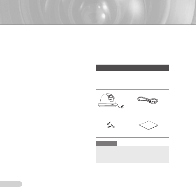
Checking components in the package
Please check your camera and accessories
are included in the package. Those
components are as shown below:
Camera Test Monitor Cable
Tab screw User’s Guide
Note
The test monitor cable is used to test the camera
by connecting to a portable display. If you really
want to connect the camera to a monitoring
display, use the BNC cable.
Page 7
ENG
7
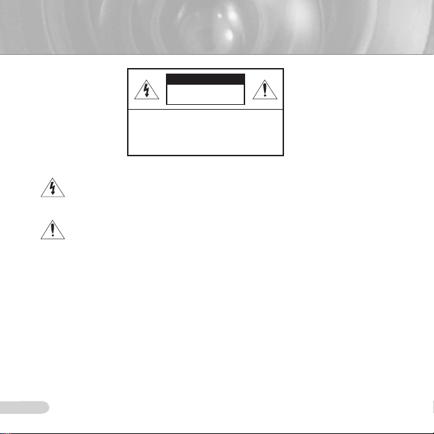
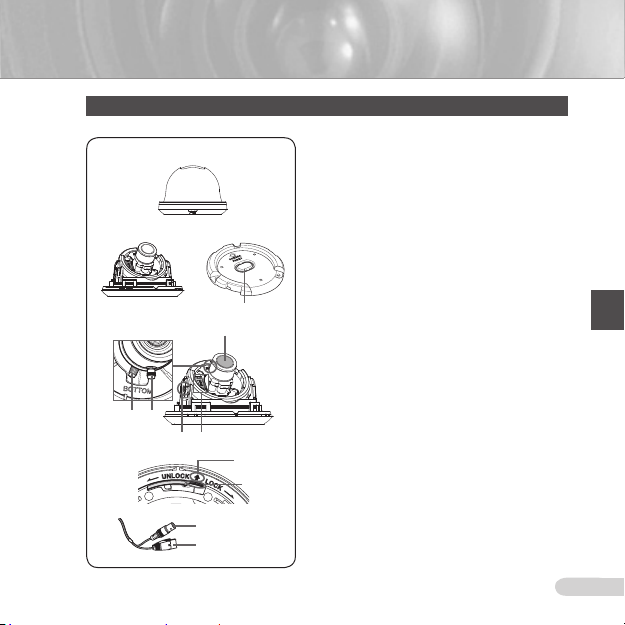
Components of your camera
Your camera has the following components:
1
2
3
4
Lens
6
5
7 8
9
0
!
Video connector
Power connector
1
2
3
4
5
6
7
8
9
0
!
Cover dome: Covers the main body for protection.
Main body: Includes a lens, a switch board, a PCB
board, screws, and such.
Mount bracket: Used as a ceiling or wall xture. It
is xed using three long tab screws provided in the
package.
Cable Stopper: If drawing the cable from a hole in
the ceiling, remove this stopper and pass the cable
through the opening to connect.
Zoom lever: Using this lever, the lens zoom can be
adjusted and xed.
Focus lever: The lens focus can be adjusted by
rotating it left or right. Rotate it clockwise for xing.
Tiltxingscrew: Using this screw, the slope of the
lens can be adjusted and xed.
Switch board: Includes two kinds of control switches
such as function switches and phase-control switches.
The board has eight function switches in the middle
and two phase-control buttons on each side of the
function switch area.
Installation Guide Mark: This mark must be aligned
with the marking on the bracket when attaching the
camera to the bracket.
Lock releaser: Push it outward and rotate the main
body in UNLOCK direction when you want to remove
the Mount bracket from the Main body or to remove
the installed camera from the Mount bracket.
Cable: Connect the Video connector to BNC cable
and Power connector to power adapter.
Page 8
9
Installation
Setting switches
❚
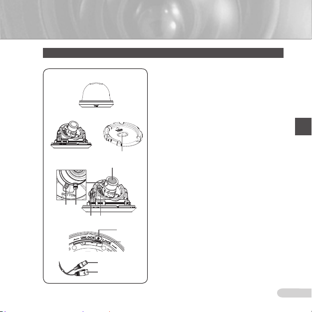
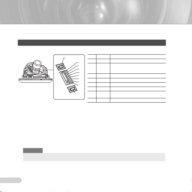
Setting function switches
To set the available functions on your camera, adjust eight switches as shown below:
DEC
1. Switch 1 (LL): When this switch is set to OFF, the camera operates in the internal
synchronization mode, while when it is set to ON, the camera operates in the line lock mode.
In the internal synchronization mode, the camera always uses an inside crystal oscillator for
synchronization. However if multiple cameras are connected to a sequential switcher, picture
rolling or ickering may occur when switching from one camera to another. In this case, you
can set this switch to ON to solve this problem.
The line lock mode allows the camera to use the phase of the AC power as the
synchronization reference. In this mode, you can use the phase control buttons(INC/DEC).
Note
When you are using the DC 12V power, set this switch to OFF. The line lock feature will not normally
operate even when the switch is set to ON.
Set the LL switch to ON while the AC power is connected. If any picture roll happens, you have
to adjust the phase using the phase-control buttons. Press the INC or DEC button to increase or
decrease the phase by one degree.
No Name Brief description
1 LL Line lock ON/OFF
8
2 LSS Sens-up or Low speed shutter ON/OFF
7
6
3 H-REV Horizontal reverse ON/OFF
5
4 V-REV Vertical reverse ON/OFF
4
5 BLC Backlight compensation ON/OFF
3
2
6 FL Flickerless ON/OFF
1
7 D/N
8 AWB Automatic white balance ON/OFF
INC
Automatic switching between color and
black & white ON/OFF
8
Page 9

ENG
9
2. Switch 2 (LSS): This sens-up mode accumulates the image elds in memory to reduce
noise but increase the brightness and contrast rate. When this switch is set to ON, the
camera automatically switches to a maximum of 128 times of image acquisition speed to
implement a clear picture for darker image.
3. Switch 3 (H-REV): When this switch is set to ON, the camera image is reversed horizontally.
If you want to monitor your site using a mirror, you can use this feature to see the right
image.
4. Switch 4 (V-REV): When this switch is set to ON, the camera image is reversed vertically.
If your camera reluctantly displays the vertically reversed image, you can use this feature to
see the right image.
5. Switch 5 (BLC): When this switch is set to ON, you can view a clear image even though the
camera faces any excessive light such as sunlight and uorescent light. When it is set to
OFF, the subject with excessive light is not clearly shown.
6. Switch 6 (FL): When this switch is set to ON, the shutter speed is xed to 1/100 sec (for
NTSC) or 1/120 sec (for PAL) to prevent screen from ickering by the disaccordance
between vertical synchronous frequency (50Hz for NTSC, 60Hz for PAL) and on-and-off
frequency of a light.
7. Switch 7 (D/N): When this switch is set to ON, the camera automatically switches between
color and B&W according to the brightness of the vicinity.
8. Switch 8 (AWB): This switch adjusts white balancing. When this switch is set to ON, this
camera operates in ATW mode, and in case of OFF, this camera operates in AWC mode.
ATW (Auto Tracking White Balance): The color temperature is automatically adjusted according to the
environmental change. (Approx. 2000°K to 11,000°K)
AWC (Auto White Balance Control): It stores the color temperature just when the switch is changed to
OFF. Accordingly color temperatures are adjusted by the stored value.
Caution
-. The IRIS setting range for the camera is approximately 80 to 120 IRE. It means the camera does not
provide the IRIS full open/close feature but the restricted variation range.
-. Use the camera after setting to the proper level (80 IRE or above) because the IRIS hunting may
occur when the level is 75 IRE or below.
Page 10
11
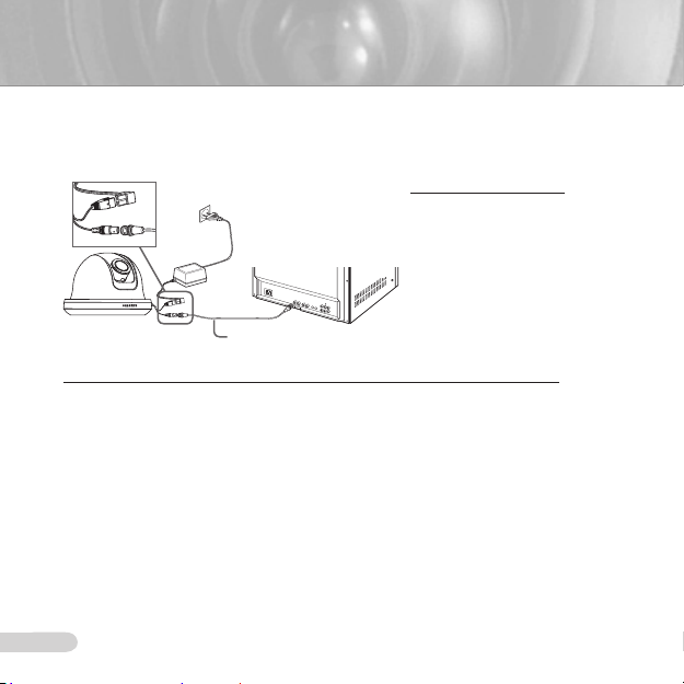
Connecting cables and changing the settings
❚
Before installing your camera, you have to adjust the lens focus, zoom, and switch settings.
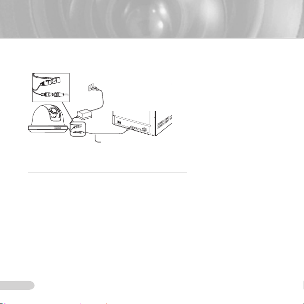
To connect cables
1. Connect the BNC cable
to the Video connector
attached on your camera.
Monitor
BNC Cable
2. Connect the BNC cable
to the Video Input on a
monitor.
3. Connect the power adapter
to the Power connector
attached on your camera.
When the monitor is turned
on, the camera image
appears.
To adjust the lens focus, zoom, and function settings
1. Remove the Cover dome and Inner cover. For more details about the removing procedures,
see “Installation procedure,” in the Installing camera section on the next page.
2. Adjust the focus, zoom, and function settings of your camera using the Focus lever, Zoom
lever, and Switch board while you are viewing the image on the screen.
3. If you want to x the adjusted focus and zoom, screw up the levers.
10
Page 11
ENG
11
Installing camera
❚
Before installation
Before installing your camera, you have to read the following cautions:
You have to check whether the location (ceiling or wall) can bear ve times the weight of your camera.
Don’t let the cable to be caught in improper place or the electric line cover to be damaged. Otherwise it
may cause a breakdown or re.
When installing your camera, don’t allow any person to approach the installation site. If you have any
valuable things under the place, move them away.
Partial blind spot can occur at tilt angles of less than 20°, depending on the lens conguration.
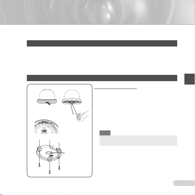
Installation procedure
1
2
3
Ceiling mount
opener
To install your camera
Pry up the outer casing with a at-head screwdriver
1
to remove the protective cover from the Main body of
the camera.
Remove the Mount bracket from the Main body by
2
rotating the Main body in the UNLOCK direction while
pushing the Lock releaser outward. If it is not easily
done, rotate the Mount bracket in the LOCK direction
while holding small holes on the Mount bracket.
Fix the Mount bracket to the location (ceiling or wall)
3
with supplied three screws.
Note
The CAMERA FRONT sign on the Mount bracket
should face the camera monitoring area.
Page 12

13
If a hole has been drilled on the bracket installation surface for cable access, press down to remove
4
the Cable Stopper and then draw the cable in. If connecting through the side of the camera, use the
empty space opposite to the side marked CAMERA FRONT.
Now attach the Main body to the Mount bracket by rotating it in the LOCK direction after aligning
5
the Groove mark on the Main body with the wide groove around the CAMERA FRONT inlay.
Adjust the camera direction. For more details on the direction control, see “Adjusting the camera
6
direction,” on the same page. When required to adjust the zoom and focus for your camera, see
“Connecting cables and changing the settings,” on page 10.
Attach the Inner cover to the Main body by pressing it until a “click” sound is heard after aligning
7
two screw holes on the Wing lockers of the Inner cover with two screw holes on the Main body’s
left and right sides.
Finally attach the Cover dome to the Main body by pressing it until a “click” sound is heard after
8
aligning the bump inside the Cover dome with the Groove mark on the Main body.
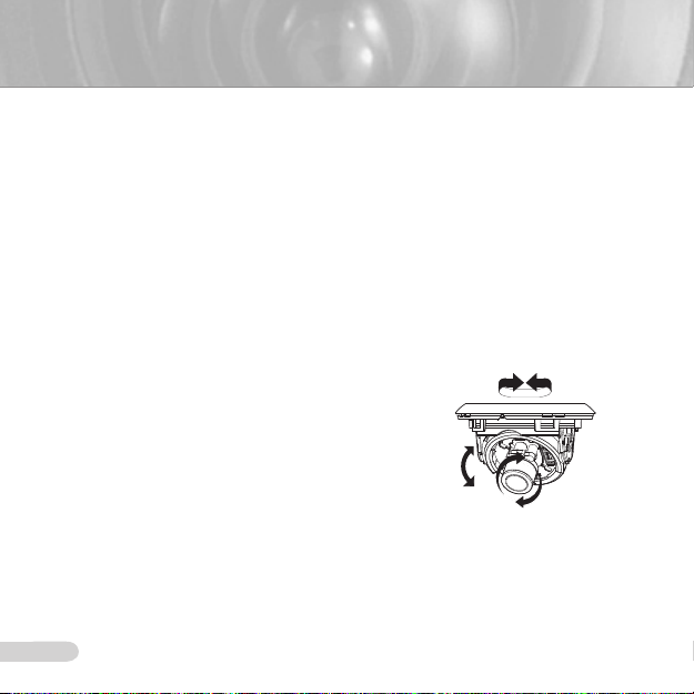
Adjusting the camera direction
❚
When the camera is xed on the ceiling, you can adjust
the camera viewing angle. You can rotate your camera
leftward or rightward (Panning), and can change the slope
of your camera upward or downward (Tilting).
In case of panning, the rotation limit of your camera is
set to 355 degree (100 degree clockwise and 255 degree
counterclockwise). The rotation is stopped by the Stopper
inside of the camera. For panning control, rst unfasten
two screws located on the bottom and rotate in the
direction you want, and then fasten them to x the camera.
Tilt can be adjusted between 0° to 90°; however, tilt
angles of less than 20° may result in a partial blind spot,
depending on your lens conguration. To x the location
after adjusting the tilting angle, use the Tiltxingscrews.
To adjust the focus and zoom of your camera, use the Zoom lever and Focus lever. When
you install the camera on the inclined ceiling or wall, you can rotate the camera lens to see
a correct direction image.
Tilting
Panning
Lens rotation
12
Page 13
ENG
13
SCC-B5342/B5343
Page 14
15
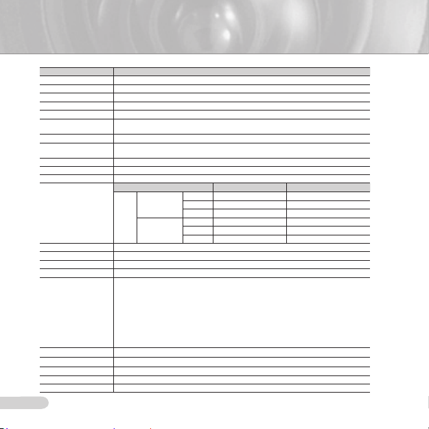
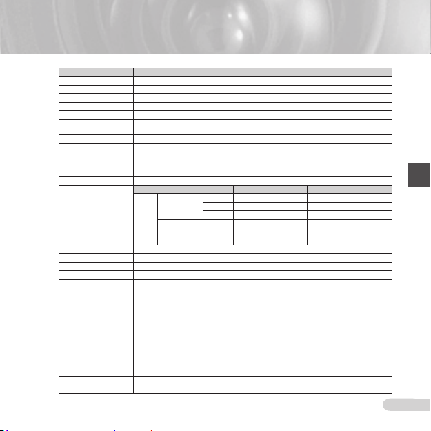
Appendix A: Specications for NTSC Standard
Item Details
Product type CCTV color dome camera
Power input AC 24V ± 10% (60Hz ± 0.3 Hz), DC 12V +10%/-5%
Broadcast type NTSC Standard System (525 Lines, 60 Fields)
Power consumption Approx. 1.7W
Image device 1/3 inch IT Type Super-HAD CCD
Pixels
Scanning mode 525 Lines, 2:1 Interlace
Scanning line frequency
Synchronization mode INT/Line Lock (Adjusting the phase using INC/DEC button)
Horizontal resolution 540 TV Lines
S/N Ratio Approx. 50dB
Min. object illumination
Signal output
Lens Auto Iris (DC) / Focal length: 2.5 to 6.0mm / Aperture ratio: 1.2
PAN function Range: 0 to 355° (100 degree clockwise and 255 degree counterclockwise)
TILT function Range: 0 to 90°
Controls
Product color SCC-B5342N/B5343N : White
Operation temperature -10°C to +50°C
Operation humidity Up to 90%
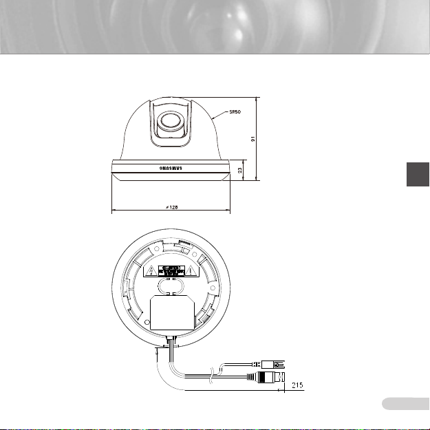
Size 128(Ø) x 91(H)mm
Weight 327g
14
Total: 811(H) x 508(V), 410,000 pixels
Effective: 768(H) x 494(V), 380,000 pixels
Horizontal: 15.734Hz(INT)/15.750Hz(LL)
Vertical: 59.94Hz(INT)/60Hz(LL)
SCC-B5343 (Color/BW) SCC-B5342 (Color/BW)
50IRE 0.4/0.04Lux 0.4/0.4Lux
Sens-up Off
F1.2
Sens-up x128
COMPOSITE Video(1.0 Vp-p, 75ohm, BNC), Test Monitor OUT(1.0 Vp-p, 75ohm, Harness cable)
Line Lock (LL)
Sens-Up; Low Speed Shutter(LSS)
Horizontal Reverse (H-REV)
Vertical Reverse (V-REV)
Backlight compensation (BLC)
Flickerless (FL)
Switching between color and B&W modes (D/N)
Auto white balancing (AWB)
Digital noise reduction (DNR)
Dynamic CCD defect compensation
30IRE 0.24/0.024Lux 0.24/0.24Lux
15IRE 0.12/0.012Lux 0.12/0.12Lux
50IRE 0.0031/0.00031Lux 0.0031/0.0031Lux
30IRE 0.0019/0.00019Lux 0.0019/0.0019Lux
15IRE 0.0009/0.00009Lux 0.0009/0.0009Lux
Page 15
ENG
15
Appendix B: Specications for PAL Standard
Item Details
Product type CCTV color dome camera
Power input AC 24V ± 10% (50Hz ± 0.3 Hz), DC 12V +10%/-5%
Broadcast type PAL Standard System (625 Lines, 50 Fields)
Power consumption Approx. 1.7W
Image device 1/3 inch IT Type Super-HAD CCD
Pixels
Scanning mode 625 Lines, 2:1 Interlace
Scanning line frequency
Synchronization mode INT/Line Lock (Adjusting the phase using INC/DEC button)
Horizontal resolution 540 TV Lines
S/N Ratio Approx. 50dB
Min. object illumination
Signal output
Lens Auto Iris (DC) / Focal length: 2.5 to 6.0mm / Aperture ratio: 1.2
PAN function Range: 0 to 355° (100 degree clockwise and 255 degree counterclockwise)
TILT function Range: 0 to 90°
Controls
Product color SCC-B5342P/B5343P : White
Operation temperature -10°C to +50°C
Operation humidity Up to 90%
Size 128(Ø) x 91(H)mm
Weight 327g
Total: 795(H) x 596(V), 470,000 pixels
Effective: 752(H) x 582(V), 440,000 pixels
Horizontal: 15.625Hz(INT)/15.625Hz(LL)
Vertical: 50Hz(INT)/50Hz(LL)
SCC-B5343 (Color/BW) SCC-B5342 (Color/BW)
50IRE 0.4/0.04Lux 0.4/0.4Lux
Sens-up Off
F1.2
Sens-up x128
COMPOSITE Video(1.0 Vp-p, 75ohm, BNC), Test Monitor OUT(1.0 Vp-p, 75ohm, Harness cable)
Line Lock (LL)
Sens-Up; Low Speed Shutter(LSS)
Horizontal Reverse (H-REV)
Vertical Reverse (V-REV)
Backlight compensation (BLC)
Flickerless (FL)
Switching between color and B&W modes (D/N)
Auto white balancing (AWB)
Digital noise reduction (DNR)
Dynamic CCD defect compensation
30IRE 0.24/0.024Lux 0.24/0.24Lux
15IRE 0.12/0.012Lux 0.12/0.12Lux
50IRE 0.0031/0.00031Lux 0.0031/0.0031Lux
30IRE 0.0019/0.00019Lux 0.0019/0.0019Lux
15IRE 0.0009/0.00009Lux 0.0009/0.0009Lux
Page 16
Correct Disposal of This Product
(Waste Electrical & Electronic Equipment)
(Applicable in the European Union and other European countries with separate
collection systems)
This marking shown on the product or its literature, indicates that it should
not be disposed with other household wastes at the end of its working life. To
prevent possible harm to the environment or human health from uncontrolled
waste disposal, please separate this from other types of wastes and recycle it
responsibly to promote the sustainable reuse of material resources.
Household users should contact either the retailer where they purchased this
product, or their local government ofce, for details of where and how they can
take this item for environmentally safe recycling.
Business users should contact their supplier and check the terms and conditions
of the purchase contract. This product should not be mixed with other commercial
wastes for disposal.
Page 17
SCC-B5342
SCC-B5343
Caméra Dôme Numérique Couleur
Mode d’emploi
imaginez les possibilités
Merci d’avoir acheté un produit Samsung.
Pour bénécier d’un service plus complet,
veuillez vous enregistrer sur
www.samsung.com/global/register
FRA
Page 18
3
PRÉCAUTIONS DE SÉCURITÉ
ATTENTION
RISQUE DE ECHOC ELECTRIQUE NE PAS OUVRIR
ATTENTION : POUR REDUIRE LES RISQUES DE CHOCS ELECTRIQUES, NE PAS
OUVRIR LE COUVERCLE ARRIERE. LES PIECES INTERIEURES NE SONT PAS
ACCESSIBLES A L’UTILISATEUR. FAITES APPEL AU PERSONNEL DE MAINTENANCE
Ce symbole indique la présence,
dans cette unité, d’une tension élevée
et avise des risques de décharge
électrique existants.
Ce symbole indique la présence,
dans cette unité, d’une tension élevée
et avise des risques de décharge
électrique existants.
ATTENTION
An de réduire le risque d’incendie ou de
•
décharge électrique, n’exposez pas cet
appareil à la pluie ni à l’humidité.
ATTENTION
1. Assurez-vous d’utiliser uniquement
l’adaptateur standard spécié dans la che
des caractéristiques techniques. Utiliser
tout autre adaptateur peut provoquer
des risques d’incendie ou des chocs
électriques et endommager le produit.
2. Un branchement incorrect de
l’alimentation électrique ou un mauvais
remplacement de la pile peut provoquer
des risques d’incendie, des chocs
électriques ou des dommages au produit.
2
QUALIFIE.
3. Ne pas connecter plusieurs caméras à
un seul adaptateur. Dépasser la capacité
peut générer une chaleur anormale ou un
risque d’incendie.
4. Branchez correctement le cordon d’
alimentation dans la prise. Une mauvaise
connexion peut provoquer des risques d’
incendie.
5. Lors de l’installation de la caméra,
attachez-la fermement et en toute sécurité.
Une caméra qui tombe peut causer des
blessures.
6. Ne placez pas d’objets conducteurs
(tourne-vis, pièces de monnaie, objets en
métal, etc...par exemple) ou des récipients
remplis d’eau sur la caméra. Cela peut
causer des blessures dues au feu, au choc
électrique ou à la chute d’objets.
7. Ne pas installez l’appareil dans des lieux
humides, poussiéreux ou couverts de suie.
Cela peut provoquer des risques
d’incendie ou des chocs électriques.
8. Si vous constatez une odeur ou une fumée
inhabituelle provenant de l’appareil, arrêtez
immédiatement son utilisation. Dans de
tel cas, déconnectez immédiatement
la source d’alimentation et contactez le
centre de maintenance. Si vous continuez
à utiliser le produit dans de telle condition,
cela peut provoquer des risques d’incendie
ou des chocs électriques.
Page 19

3
FRA
9. Si ce produit ne fonctionne pas
normalement, contactez le centre de
maintenance le plus proche. Ne jamais
démonter ou modier le produit de quelque
manière que ce soit. (SAMSUNG n’est
pas responsable des problèmes causés
par des modications ou des tentatives de
réparation non autorisées.)
10. Lors du nettoyage, ne pas diriger l’eau
directement sur les pièces de l’appareil.
Cela peut provoquer des risques
d’incendie ou des chocs électriques.
MISE EN GARDE
1. Ne pas faire tomber des objets sur le
produit ou lui faire subir des chocs.
Eloignez le produit des emplacements
soumis aux vibrations ou interférences
magnétiques excessives.
2. Ne pas installer le produit à des
emplacements soumis aux températures
élevées (supérieures à 50 °C), aux
températures faibles (inférieures à -10°
C), ou à une humidité élevée. Cela peut
provoquer des risques d’incendie ou des
chocs électriques.
3. Si vous désirez changer le produit de
place, assurez-vous de le mettre hors
tension, déplacez-le et réinstallez-le.
4.
Débranchez le cordon d’alimentation de
la prise lorsqu’il y a des éclairs. Ne pas
appliquer cette consigne peut provoquer des
risques d’incendie ou endommager le produit.
5.
Eloignez le produit des rayons directs du
soleil ou des sources de radiation de chaleur.
Cela peut provoquer des risques d’incendie.
6. Installez le produit dans un lieu où la
ventilation est sufsante.
7. Evitez de pointer la caméra directement
vers des objets extrêmement brillants
comme le soleil, cela peut endommager le
capteur d’image CCD.
8. Veillez à éviter toute projection sur l’
appareil et ne placez jamais de récipients
contenant un liquide (ex. : vase) dessus.
9. La prise d’alimentation fait ofce de
système de déconnexion ; elle doit donc
rester disponible en permanence.
Page 20

5
INSTRUCTIONS IMPORTANTES RELATIVES À LA SÉCURITÉ
1. Veuillez lire ces instructions.
2. Conservez ces instructions.
3. Prêtez attention à tous les avertissements.
4. Veuillez suivre toutes les instructions.
5. N’utilisez pas cet appareil à proximité de
l’eau.
6. Nettoyez-le avec un tissu sec.
7. N’obstruez pas les ouvertures de
ventilation. Procédez à l’installation
conformément aux instructions du
fabricant.
8. Ne pas installer l’appareil à proximité de
sources de chaleur comme les radiateurs,
les registres de chaleur et les autres
appareils (incluant les amplicateurs)
produisant de la chaleur.
9. Veillez à vous conformer aux sécurités
des prises de terre et polarisées. Une
prise dite polarisée est composée de deux
ches, une plus large que l’autre. Une
prise de terre est composée de deux ches
et d’une troisième che pour la terre. La
troisième che, plus large que les deux
autres, est fournie pour votre sécurité. Si
la prise qui vous est fournie ne correspond
pas à votre prise murale, demandez à un
électricien de remplacer la prise obsolète.
10. Veillez à ce que personne ne marche ou
se prenne les pieds dans le cordon
d’alimentation et particulièrement au
niveau des ches et des prises de courant
et au niveau où ils se situent.
11. N’utilisez que des accessoires ou des
produits additionnels spéciés par le
fabricant.
12. N’utilisez que des chariots, des pieds,
trépieds, ou tables spéciés par le fabricant
ou vendus avec l’appareil.
4
13. Débranchez cet appareil. Si vous utilisez
un chariot, faîtes attention lorsque que
vous déplacez l’appareil et le chariot
pour éviter les blessures causées par un
renversement.
14. Veuillez faire appel au personnel qualié
pour tous travaux de maintenance. Les
travaux de maintenance sont nécessaires
si l’appareil a été endommagé de quelque
manière que ce soit, comme cordon
d’alimentation endommagé, liquide
répandu, objets tombés sur l’appareil,
appareil exposé à la pluie et à l’humidité,
il ne fonctionne pas normalement ou est
tombé par terre.
Page 21

5
FRA
Table des matières
Synthèse ......................................................................................6
A propos de ce guide ....................................................................6
Synthèse du produit ...................................................................... 6
Caractéristiques principales ........................................................6
Composants ................................................................................... 6
Vérication des composants dans l’emballage .........................6
Composants de votre caméra ...................................................7
Installation ..................................................................................8
Réglage des interrupteurs ............................................................8
Régler les interrupteurs de fonction ..........................................8
Connexion des câbles et modication des réglages .............. 10
Installation de la caméra ............................................................ 11
Avant l’installation ...................................................................11
Procédure d’installation ........................................................... 11
Ajuster la direction de la caméra ..............................................12
Appendice A : Caractéristiques NTSC Standard ......... 14
Appendice B : Caractéristiques PAL Standard ............15
Page 22
7
Synthèse
A propos de ce guide
❚
Ce guide utilisateur inclut les instructions
de base relatives à ce produit. Nous
recommandons à tous les utilisateurs de lire
ce guide avant d’utiliser l’appareil.
Ce guide est divisé comme suit :
Le chapitre 1, “Synthèse” introduit le guide
utilisateur et les informations relatives au produit.
(Ce chapitre)
Le chapitre 2, “Installation” explique comment
régler et installer le produit.
L’appendice, “Caractéristiques”, vous fournit les
caractéristiques de ce produit.
Synthèse du produit
❚
Ce produit est une caméra dôme à haute
résolution (540 lignes TV) équipée d’une optique
à focale variable, sans retard dynamique lors de
l’implémentation des images de mouvement, elle
bénécie de fonctions comme la réduction de
bruit numérique (DNR), la réduction des défauts
CCD en temps réel, et l’obturation à vitesse
réduite (Vitesse ambiante du son (LSS : Auto
x 128) pour implémenter une qualié d’image
claire, et une compensation de couleur Jour /
Nuit.
Caractéristiques principales
❚
Alimentation : CC 12V/CA 24V
Fonctions spéciales
Commande de verrouillage de ligne (LL)
Balance automatique des blancs
Renversement de l’image horizontal/vertical
Commande anti-tremblement
Commande d’obturation à vitesse réduite
Commande de la compensation du
rétroéclairage
6
Passage automatique entre les modes noir &
blanc et couleur.
Equipé d’une optique à focale variable
Fonction de diaphragme automatique
Réduction automatique de bruit (DNR)
Compensation des défauts CCD dynamique
Composants
❚
Vérication des composants dans l’emballage
Veuillez vérier que votre caméra et ses
accessoires soient inclus dans l’emballage.
Ces composants sont comme illustrés
ci-dessous :
Caméra Câble du moniteur de test
Vis Guide de l’utilisateur
Remarque
Le câble du moniteur de test est utilisé pour tester
la caméra en la connectant à un écran portable.
Si vous désirez vraiment connecter la caméra à
un écran moniteur, utilisez le câble BNC.
Page 23
7
FRA
Composants de votre caméra
Votre caméra est composée des éléments suivants:
1
2
3
4
Optique
6
5
7 8
9
0
!
Connecteur vidéo
Connecteur
d’alimentation
1 Couvercle du dôme: Couvre le corps principal pour le
protéger.
2 Corps principal: Inclut l’optique, le dispositif de
commande, une carte de circuit imprimé, les vis et
accessoires associés.
3 Support de xation: Utilisé pour xer la caméra sur
un mur ou au plafond. Fixé à l’aide de 3 longues vis
fournies dans l’emballage.
4 Bloqueur de câble: Si vous tirez le câble d’un trou
dans le plafond, retirez ce bloqueur et passez le câble à
travers l’ouverture pour le connecter.
5 Levier de zoom: Utilisez ce levier pour ajuster et xer le
zoom de l’optique.
6 Levier de mise au point: Vous pouvez ajuster la mise
au point de l’optique en la tournant vers la gauche ou
la droite. Tournez-le dans le sens des aiguilles d’une
montre pour le xer.
7 Vis de xation de bascule : Vous pouvez ajuster ou
xer, à l’aide de cette vis, le coefcient angulaire de
l’optique.
8 Dispositif de commande: Inclut deux sortes de
commutateurs de commande comme les commutateurs
de fonction et les commutateurs de commande de la
phase. Le dispositif de commande est composé de huit
commutateurs de fonction situés au milieu et de deux
commutateurs de commande de la phase sur chaque
côté de la zone des commutateurs de fonction.
9 Marque de guide d’installation: Cette marque doit être
alignée avec la marque sur l’équerre lors de la xation
de la caméra à l’équerre.
0 Déverrouilleur : Tirez-le et tournez le corps principal en
direction de DEVERROUILLAGE si vous désirez retirer
le support de xation du corps principal ou retirer la
caméra installée sur le support de xation.
! Câble: Connectez le connecteur vidéo au câble BNC et
le connecteur d’alimentation à l’adaptateur.
Page 24
9
Installation
Réglage des interrupteurs
❚
Régler les interrupteurs de fonction
Pour régler les fonctions disponibles sur votre caméra, ajustez les huit interrupteurs comme
indiqué ci-dessous :
DEC
1. Interrupteur 1 (LL): Si cet interrupteur est positionné sur OFF, la caméra fonctionne en
mode de synchronisation interne, alors que si réglé sur ON, la caméra fonctionne en mode
de verrouillage de ligne.
En mode de synchronisation interne, la caméra utilise toujours un oscillateur de cristal
interne pour la synchronisation. Cependant si plusieurs caméras sont connectées à un
interrupteur séquentiel, vous pouvez constater une image instable ou un tremblement lors
du passage d’une caméra à une autre. Dans ce cas, vous pouvez positionner l’interrupteur
sur ON pour résoudre le problème.
Le mode de verrouillage de ligne permet à la caméra d’utiliser la phase de l’alimentation à
courant alternatif comme référence de synchronisation. Dans ce mode, vous pouvez utiliser,
les boutons de commande de la phase (INC/DEC).
Remarque
Si vous utilisez l’alimentation 12 V CC, réglez l’interrupteur sur OFF. La fonction de verrouillage de
ligne ne fonctionnera pas même si l’interrupteur est en position ON.
Mettre l’interrupteur LL en position ON tandis que l’alimentation CA est connectée. Si vous
constatez une instabilité de l’image, vous pouvez ajuster la phase à l’aide des boutons de
commande de la phase. Appuyez sur le bouton INC ouDEC pour augmenter ou réduire la phase
par incrément d’un degré.
8
N° Nom Brève description
1 LL Verrouillage de ligne ON/OFF
8
7
2 LSS
6
5
3 H-REV Renversement horizontal ON/OFF
4
3
4 V-REV Renversement vertical ON/OFF
2
5 BLC Compensation du rétroéclairage ON/OFF
1
6 FL
7 D/N
INC
8 AWB Balance automatique des blancs ON/OFF
Capteur d’obturation ou Sens-up
(captation) de vitesse haute ou faible
ON/OFF
Anti-tremblement ON /OFF
Passage automatique entre le noir &
blanc et la couleur ON/OFF
Page 25

9
FRA
2. Interrupteur 2 (LSS): Ce mode de captation (sens-up) accumule le champs de l’image en
mémoire pour réduire le bruit mais aussi augmenter le taux de clarté et de contraste. Une
fois l’interrupteur sur ON, la caméra passe automatiquement à une vitesse maximum
d’acquisition de l’image de 128 fois pour implémenter une image claire à la place d’une
image plus sombre.
3. Interrupteur 3 (H-REV): Une fois cet interrupteur sur ON, l’image de la caméra est
horizontalement renversée. Si vous désirez effectuer la surveillance de votre site à l’aide
d’un miroir, vous pouvez utiliser cette fonction pour voir la bonne image.
4. Interrupteur 4 (V-REV): Une fois cet interrupteur sur ON, l’image de la caméra est
verticalement renversée. Si votre caméra n’afche pas correctement l’image renversée,
vous pouvez utiliser cette fonction pour voir la bonne image.
5. Interrupteur 5 (BLC): Une fois cet interrupteur sur ON, vous pouvez visualiser une image
claire, bien que la caméra soit face à une lumière excessive comme les rayons du soleil
ou une lumière uorescente. Une fois positionné sur OFF, le sujet éclairé par une lumière
excessive n’apparaît pas très clairement.
6. Interrupteur 6 (FL): Une fois cette interrupteur sur ON, la vitesse de l’obturateur est xée
à 1/100 de seconde (pour le NTSC) ou de 1/120 de seconde (pour le PAL) pour empêcher
le tremblement de l’image due au désaccord entre la fréquence synchrone verticale (50 Hz
pour le NTSC, 60 Hz pour le PAL) et le signal hors fréquence/sur la même fréquence.
7. Interrupteur 7 (D/N): Une fois cet interrupteur sur ON, la caméra passe automatiquement
du Noir et Blanc à la couleur selon la clarté de l’environnement.
8. Interrupteur 8 (AWB): Cet interrupteur ajuste la balance des blancs. Une fois cet
interrupteur sur ON, cette caméra fonctionne en mode ATW, au cas où l’interrupteur est sur
OFF, la caméra fonctionne en mode AWC.
ATW (Autorepérage de la balance des blancs) : La température de la couleur est automatiquement
ajustée selon les modications apportées par l’environnement. (Environ 2000°K à 11000°K)
ATW (Commande automatique de la balance des blancs) Il enregistre la température de la couleur une
fois l’interrupteur en position OFF. Les températures de la couleur sont conformément ajustées grâce
aux valeurs enregistrées.
Attention
-. La gamme de réglage du diaphragme de la caméra est entre 80 et 120 IRE. En d’autre terme, la
caméra ne fournit pas de fonction d’ouverture/fermeture entière du diaphragme mais seulement la
gamme de variation restreinte.
-. Utilisez la caméra après avoir réglé le niveau approprié (80 IRE ou plus), dans le cas contraire, vous
pourrez constater une instabilité du diaphragme si le niveau est réglé à 75 IRE ou moins.
Page 26
11
Connexion des câbles et modication des réglages
❚
Avant d’installer votre caméra, vous devez régler la mise au point de l’optique, du zoom et
effectuer les réglages des interrupteurs.
Connexion des câbles
1. Connectez le câble BNC au
connecteur vidéo xé à votre
caméra.
Moniteur
Câble BNC
2. Connectez le câble BNC à
l’entrée vidéo du moniteur.
3. Connectez l’adaptateur
électrique au connecteur
d’alimentation xé à votre
caméra. Une fois le moniteur
activé, les images de la
caméra apparaissent.
Pour régler la mise au point, le zoom et effectuer les réglages de fonction
1. Retirez le couvercle du dôme et le couvercle intérieur. Pour obtenir plus de détails sur les
procédures relatives au retrait, voir la “Procédure d’installation” dans la section installation
de la caméra sur la page suivante.
2. Réglez la mise au point, le zoom et effectuez les réglages des fonctions de votre caméra à
l’aide du levier de mise au point, du levier de zoom et du dispositif de commande tandis que
vous visualisez l’image sur l’écran.
3. Si vous désirez xer la mise au point et le zoom ajusté, vissez les leviers.
10
Page 27

11
FRA
❚
Installation de la caméra
Avant l’installation
Avant l’installation de votre caméra, veuillez lire les mises en garde suivantes :
Vous devez vérier si le lieu d’installation (plafond ou mur) peut supporter le poids de cinq fois votre
caméra.
Ne laissez pas le câble pendre à un emplacement inapproprié ou le couvercle de la ligne électrique
être endommagé. Cela peut causer un court-circuit ou un incendie.
Lors de l’installation de votre caméra, ne laissez personne s’approcher du site d’installation. Si des
objets de valeur se situent sous l’emplacement d’installation, déplacez-les.
L’angle mort partiel peut apparaître dans les angles de basculement de moins de 20°, en fonction de la
conguration de l’objectif.
Procédure d’installation
1
2
3
Ouvreur du
plafonnier
Installation de votre caméra
1 Pour enlever le couvercle de protection du corps
principal de la caméra, soulevez le logement extérieur
en faisant levier avec un tournevis plat.
2
Retirez le support de xation du corps principal
en tournant le corps principal en position de
DEVERROUILLAGE tout en tirant le déverrouilleur.
Si vous n’y arrivez pas facilement, tournez le support
de xation en direction de VERROUILLAGE tout en
tenant les petits trous du support de xation.
3
Fixez le support de xation sur le lieu
d’installation (mur ou plafond) avec les trois vis
fournies.
Remarque
Le signe CAMERA FRONT (AVANT DE LA CAMERA)
situé sur le support de xation doit faire face à la
zone de contrôle de la caméra.
Page 28
13
Si un trou a été percé sur la surface d’installation de l’équerre pour l’accès au câble, appuyer pour
4
retirer le bloqueur de câble et passer ensuite le câble dedans. En cas de connexion par le côté de la
caméra, utiliser l’espace vide opposé au côté marqué DEVANT DE CAMERA.
Fixez maintenant le corps principal au support de xation en le tournant en direction de
5
VERROUILLAGE après avoir aligné la rainure sur le corps principal à l’aide de la large rainure située
autour de l’incrustation CAMERA FRONT (AVANT DE LA CAMERA).
Ajuster la direction de la caméra. Pour obtenir plus de détails sur la commande de direction, voir
6
la section “Ajuster la direction de la caméra” sur la même page. Si vous devez régler le zoom et la
mise au point de votre caméra, reportez-vous à la section “Connexion des câbles et modication des
réglages” en page 10.
Fixez le couvercle intérieur au corps principal en appuyant dessus jusqu’à entendre un “clic” après
7
avoir aligné les deux trous sur le verrouilleur de l’aile du couvercle intérieur à l’aide des deux trous
situés sur les côtés gauches et droits du corps principal.
Fixez enn le couvercle du dôme au corps principal en appuyant dessus jusqu’à entendre un
8
“clic” après avoir aligné la bosse à l’intérieur du couvercle du dôme avec la rainure située sur le
couvercle principal.
Ajuster la direction de la caméra
❚
Une fois la caméra xée au plafond, vous pouvez
ajuster son angle de vue. Vous pouvez tourner votre
caméra sur la gauche ou sur la droite (Panoramique) et
remonter ou descendre son angle (basculement).
Pour un panorama, la limite de rotation de la caméra
est réglée à 355 degrés (100 degrés dans le sens
des aiguilles d’une montre et 255 degrés dans le sans
inverse aux aiguilles d’une montre). La rotation est
arrêtée par un Stop à l’intérieur de la caméra. Pour la
commande panoramique, desserrez dans un premier
temps les deux vis situées sur le bas et tournez dans la
direction de votre choix, puis resserrez les vis pour xer
la caméra.
Le basculement peut être réglé entre 0° et 90° ; toutefois, les angles de basculement de moins
de 20° peuvent engendrer un angle mort partiel, en fonction de la conguration de l’objectif. Pour
xer l’emplacement après avoir ajusté l’angle de basculement, utilisez les vis de xation de
bascule.
Pour régler la mise au point et le zoom de votre caméra, utilisez le levier de zoom et le levier de
mise au point. Si vous installez la caméra sur un mur ou un plafond incliné, vous pouvez tourner
l’optique de la caméra pour apercevoir une image directionnelle correcte.
Basculement
Panorama
Rotation de l’optique
12
Page 29

13
FRA
SCC-B5342/B5343
Page 30

15
Appendice A : Caractéristiques NTSC Standard
Fonctions Détails
Type de produit Caméra dôme couleur CCTV
Entrée alimentation 24V CA ± 10% (60Hz ± 0,3 Hz), 12V CC +10%/-5%
Type de diffusion Système standard NTSC (525 lignes, 60 champs)
Consommation électrique
Dispositif d’image IT Type Super-HAD CCD 1/3 pouce
Pixels
Mode de balayage 525 lignes, Entrelacement 2:1
Fréquence de la ligne de
balayage
Mode de synchronisation
Résolution horizontale 540 Lignes TV
Rapport signal/bruit Env. 50 dB
Illumination mini. de l’
objet
Sortie de signal
Optique Diaphragme automatique (DC) / Longueur focale : 2,5 à 6,0mm / Ouverture relative : 1,2
Fonction PANORAMA
Fonction BASCULEMENT
Commandes
Couleur de produit SCC-B5342N/B5343N : Blanc
Température fonctionnelle
Humidité fonctionnelle 90% maxi
Taille 128(Ø) x 91(H)mm
Poids 327g
14
Approx. 1,7 W
Total: 811(H) x 508(V), 410 000 pixels
Effectif: 768(H) x 494(V), 380 000 pixels
Horizontal: 15,734Hz(INT)/15,750Hz(LL)
Vertical: 59,94Hz(INT)/60Hz(LL)
INT/Verrouillage de ligne (Ajuster la phase à l’aide du bouton INC/DEC)
SCC-B5343 (Color/BW) SCC-B5342 (Color/BW)
50IRE 0,4/0,04Lux 0,4/0,4Lux
Sens-up Off
F1,2
Sens-up x128
Vidéo COMPOSITE (1,0 Vp-p, 75ohm, BNC), SORTIE Moniteur de test (1,0 Vp-p, 75ohm, Câble couplé)
Etendue : 0 à 355° (100 degrés dans le sens des aiguilles d’une montre et 255 degrés dans
le sens inverse aux aiguilles d’une montre)
Etendue : 0 à 90°
Verrouillage de ligne (LL)
Sens-up ; Obturateur à vitesse réduite (LSS)
Renversement horizontal (H-REV)
Renversement vertical (V-REV)
Compensation du rétroéclairage (BLC)
Anti-tremblement (FL)
Passage du mode couleur au mode N&B (D/N)
Balance automatique des blancs (AWB)
Réduction automatique de bruit (DNR)
Compensation des défauts CCD dynamique
-10°C à +50°C
30IRE 0,24/0,024Lux 0,24/0,24Lux
15IRE 0,12/0,012Lux 0,12/0,12Lux
50IRE 0,0031/0,00031Lux 0,0031/0,0031Lux
30IRE 0,0019/0,00019Lux 0,0019/0,0019Lux
15IRE 0,0009/0,00009Lux 0,0009/0,0009Lux
Page 31

15
FRA
Appendice B : Caractéristiques PAL Standard
Fonctions Détails
Type de produit Caméra dôme couleur CCTV
Entrée alimentation 24 V CA ± 10% (50Hz ± 0,3 Hz), 12 V CC +10%/-5%
Type de diffusion Système standard PAL (625 lignes, 50 champs)
Consommation électrique
Dispositif d’image IT Type Super-HAD CCD 1/3 pouce
Pixels
Mode de balayage 625 lignes, Entrelacement 2:1
Fréquence de la ligne de
balayage
Mode de synchronisation
Résolution horizontale 540 Lignes TV
Rapport signal/bruit Env. 50 dB
Illumination mini. de l’
objet
Sortie de signal
Optique Diaphragme automatique (DC) / Longueur focale : 2,5 à 6,0mm / Ouverture relative : 1,2
Fonction PANORAMA
Fonction BASCULEMENT
Commandes
Couleur de produit SCC-B5342P/B5343P : Blanc
Température fonctionnelle
Humidité fonctionnelle 90% maxi
Taille 128(Ø) x 91(H)mm
Poids 327g
Approx. 1,7 W
Total: 795(H) x 596(V), 470 000 pixels
Effectif: 752(H) x 582(V), 440 000 pixels
Horizontal: 15,625Hz(INT)/15,625Hz(LL)
Vertical: 50Hz(INT)/50Hz(LL)
INT/Verrouillage de ligne (Ajuster la phase à l’aide du bouton INC/DEC)
SCC-B5343 (Color/BW) SCC-B5342 (Color/BW)
50IRE 0,4/0,04Lux 0,4/0,4Lux
Sens-up Off
F1,2
Sens-up x128
Vidéo COMPOSITE (1,0 Vp-p, 75ohm, BNC), SORTIE Moniteur de test (1,0 Vp-p, 75ohm, Câble couplé)
Etendue : 0 à 355° (100 degrés sens des aiguilles d’une montre et 255 degrés sens
contraire aux aiguilles d’une montre).
Etendue : 0 à 90°
Verrouillage de ligne (LL)
Sens-up ; Obturateur à vitesse réduite (LSS)
Renversement horizontal (H-REV)
Renversement vertical (V-REV)
Compensation du rétroéclairage (BLC)
Anti-tremblement (FL)
Passage du mode couleur au mode N&B (D/N)
Balance automatique des blancs (AWB)
Réduction automatique de bruit (DNR)
Compensation des défauts CCD dynamique
-10°C à +50°C
30IRE 0,24/0,024Lux 0,24/0,24Lux
15IRE 0,12/0,012Lux 0,12/0,12Lux
50IRE 0,0031/0,00031Lux 0,0031/0,0031Lux
30IRE 0,0019/0,00019Lux 0,0019/0,0019Lux
15IRE 0,0009/0,00009Lux 0,0009/0,0009Lux
Page 32

Comment éliminer ce produit
(déchets d’équipements électriques et électroniques)
(Applicable dans les pays de l’Union Européen et aux autres pays européens disposant de
systémes de collecte sélective)
Ce symbole sur le produit ou sa documentation indique qu’il ne doit pas être éliminé en n de
vie avec les autres déchets ménagers. L’élimination incontrôlée des déchets pouvant porter
préjudice à l’environnement ou à la santé humaine, veuillez le séparer des autres types de
déchets et le recycler de façon responsable. Vous favoriserez ainsi la réutilisation durable des
ressources matérielles.
Les particuliers sont invités à contacter le distributeur leur ayant vendu le produit ou à se
renseigner auprès de leur mairie pour savoir où et comment ils peuvent se débarrasser de ce
produit an qu’il soit recyclé en respectant l’environnement.
Les entreprises sont invitées à contacter leurs fournisseurs et à consulter les conditions
de leur contrat de vente. Ce produit ne doit pas être éliminé avec les autres déchets
commerciaux.
Page 33

SCC-B5342
SCC-B5343
Digitale Dome-Farbkamera
bedienungsanleitung
denken sie an die möglichkeiten
Danke für den Kauf eines Samsung Gerätes.
Um einen umfassenderen Kundendienst zu erhalten,
registrieren Sie Ihr Gerät bitte unter
www.samsung.com/global/register
GER
Page 34

3
SICHERHEITSVORKEHRUNGEN
WARNUNG
GEFAHR EINES ELEKTROSCHOCKSNICHT ÖFFNEN
WARNUNG: NICHT DIE RÜCKSEITIGE ABDECKUNG ÖFFNEN, UM DIE GEFAHR EINES ELEKTROSCHOCKS
ZU SENKEN. KEINE VOM BENUTZER ZU WARTENDE TEILE INNEN. WENDEN SIE SICH AN
Dieses Symbol zeigt an, dass bei
diesem Gerät gefährliche Spannung
Elektroschock zur Folge haben kann.
Dieses Symbol zeigt an,
dass wichtige Betriebs- und
Wartungsanleitungen in dem
Prospekt enthalten sind, der mit
diesem Gerät geliefert wird.
WARNUNG
•
Setzen Sie dieses Gerät nicht Regen
oder Feuchtigkeit aus, um die Gefahr
eines Brands oder Elektroschocks zu
reduzieren.
WARNUNG
1. Achten Sie darauf, nur den im
Datenblatt angegebenen StandardAdapter zu verwenden. Die Verwendung
eines anderen Adapters kann Brand,
Elektroschock oder Schäden am Produkt
verursachen.
2. Falscher Anschluss des Netzkabels oder
Austausch der Batterie kann Explosion,
Brand, Elektroschock oder Schäden am
Produkt zur Folge haben.
QUALIFIZIERTESKUNDENDIENSTPERSONAL.
3. Schließen Sie nicht mehrere Kameras an
einen einzelnen Adapter an. Überschreiten
der Kapazität kann abnormale Wärme oder
Brand erzeugen.
4. Schließen Sie das Netzkabel sicher an die
Steckdose an. Ein ungesicherter Anschluss
kann einen Brand verursachen.
5. Wenn Sie die Kamera installieren,
befestigen Sie sie sicher und fest.
Eine herunterfallende Kamera kann
Körperverletzungen verursachen.
6. Stellen Sie keine leitenden Gegenstände
(z.B. Schraubendreher, Münzen,
Metallgegenstände, usw.) oder Behälter mit
Wasser auf die Kamera. Dies kann sonst
Körperverletzungen aufgrund von Brand,
Elektroschock oder herunterfallenden
Gegenständen verursachen.
7.
Installieren Sie das Gerät nicht an feuchten,
staubigen oder rußigen Standorten. Dies
führt sonst zu Brand oder Elektroschock.
8. Verwenden Sie das Produkt nicht weiter,
wenn eine ungewöhnliche Geruchs- oder
Rauchentwicklung auftritt. Ziehen Sie in
diesem Fall sofort den Netzstecker und
wenden Sie sich an den Kundendienst.
Wenn Sie das Gerät unter diesen
Bedingungen weiterhin verwenden, kann
Brand oder Elektroschock resultieren.
2
Page 35

3
GER
9. Wenn dieses Produkt nicht einwandfrei
funktioniert, wenden Sie sich an den
nächstgelegenen Kundendienst. Zerlegen
oder modizieren Sie dieses Produkt nie
in irgendeiner Weise. (SAMSUNG haftet
nicht für Schäden, die durch unbefugte
Änderungen oder Reparaturversuche
verursacht werden.)
10. Spritzen Sie während der Reinigung kein
Wasser direkt auf die Produktteile. Dies
führt sonst zu Brand oder Elektroschock.
VORSICHT
1. Lassen Sie keine Gegenstände auf das
Produkt fallen oder setzen Sie es keinen
starken Stößen aus. Halten Sie sich
fern von Standorten die übermäßiger
Erschütterung oder magnetischer
Beeinussung ausgesetzt sind.
2. Installieren Sie das Gerät nicht an einem
Standort, der hohen Temperaturen (über
50°C), niedrigen Temperaturen (unter -10
°C) oder hoher Feuchtigkeit ausgesetzt
ist. Dies führt sonst zu Brand oder
Elektroschock.
3. Wenn Sie das bereits installierte Gerät
versetzen möchten, achten Sie darauf,
die Stromversorgung abzuschalten und
es dann erst zu versetzen und erneut zu
installieren.
4. Ziehen Sie den Netzstecker bei Gewitter.
Nichtbeachtung kann Brand oder Schäden
am Gerät verursachen.
5. Halten Sie das Gerät fern von
direktem Sonnenlicht und anderen
Wärmestrahlungsquellen. Dies kann sonst
zu Brand führen.
6. Installieren Sie das Gerät an einem Ort mit
guter Belüftung.
7. Zielen Sie mit der Kamera nicht direkt in
Richtung extrem heller Gegenstände wie
zum Beispiel die Sonne, da dies den
CCD-Bildsensor beschädigen kann.
8.
Das Gerät darf nicht mit Wasser oder
anderen Flüssigkeiten in Berührung kommen.
Außerdem dürfen keine mit Flüssigkeiten
gefüllten Behälter, wie beispielsweise Vasen,
darauf abgestellt werden.
9. Der Netzstecker sollte jederzeit in
Reichweite und zugänglich sein, da er aus
der Steckdose entfernt werden muss, um
das Gerät vollständig abzuschalten.
Page 36

5
SICHERHEITSHINWEISE
1. Lesen Sie diese Anweisungen.
2. Bewahren Sie sie auf.
3. Beachten Sie alle Warnungen.
4. Befolgen Sie alle Anweisungen.
5. Verwenden Sie dieses Gerät nicht in der
Nähe von Wasser.
6. Reinigen Sie es nur mit einem trockenen
Lappen.
7. Blockieren Sie keine
Belüftungsöffnungen. Installieren Sie es
gemäß den Herstelleranweisungen.
8. Installieren Sie das Gerät nicht in
der Nähe von Wärmequellen wie
beispielsweise von Radiatoren,
Heizkörpern oder anderen Geräten
(einschließlich Verstärkern), die Wärme
erzeugen.
9. Bitte achten Sie darauf, die
Schutzvorrichtung des gepolten
bzw. geerdeten Steckers nicht zu
beschädigen. Ein gepolter Stecker
verfügt über zwei Stifte, von denen
einer breiter als der andere ist. Ein
geerdeter Stecker hat zwei Stifte und
einen Erdungsstift. Der breite Stift oder
der dritte Stift ist für Ihre Sicherheit
vorgesehen. Wenn der vorgesehene
Stecker nicht in Ihre Steckdose passt,
wenden Sie sich an einen Elektriker, um
die veraltete Steckdose austauschen zu
lassen.
4
10. Schützen Sie das Netzkabel so, dass
nicht darauf getreten wird, und dass
es insbesondere an den Steckern oder
passenden Steckdosen bzw. der Stelle,
an der das Kabel das Gerät verlässt,
nicht abgeklemmt wird.
11. Verwenden Sie nur die vom Hersteller
angegebenen Zusatzgeräte/
Zubehörteile.
12. Verwenden Sie diese nur mit dem
vom Hersteller angegebenen Wagen,
Ständer, Stativ, Auage oder Tisch, oder
die mit dem Gerät zusammen verkauft
wurden.
13. Ziehen Sie den Netzstecker dieses
Geräts. Geben Sie Acht bei der
Verwendung eines Wagens, wenn
Sie die Wagen-/Gerätekombination
verschieben, um Verletzungen durch
Herunterfallen zu vermeiden.
14. Überlassen Sie alle Wartungsarbeiten
qualiziertem Kundendienstpersonal.
Wartungsarbeiten sind erforderlich,
wenn das Gerät in irgendeiner Weise
beschädigt wurde, wie zum Beispiel
ein beschädigtes Netzkabel oder
Stecker, verschüttete Flüssigkeiten oder
Gegenstände, die in das Gerät gefallen
sind, das Gerät Regen oder Feuchtigkeit
ausgesetzt wurde, nicht normal
funktioniert oder fallen gelassen wurde.
Page 37

5
GER
Inhaltsangabe
Übersicht .....................................................................................6
Über diese Anleitung .....................................................................6
Produktübersicht ........................................................................... 6
Hauptfunktionen ............................................................................6
Teile ................................................................................................6
Prüfen Sie die Teile in der Verpackung ......................................6
Einzelteile Ihrer Kamera ............................................................. 7
Installation ..................................................................................8
Einstellung der Schalter ...............................................................8
Einstellung der Funktionsschalter ..............................................8
Anschluss der Kabel und Änderung der Einstellungen ..........10
Installation der Kamera ............................................................... 11
Vor der Installation ...................................................................11
Installationsvorgang .................................................................11
Einstellen der Kamerarichtung ..................................................12
Anhang A: Spezikationen für NTSC-Standard ............14
Anhang B: Spezikationen für PAL-Standard ................15
Page 38

7
Übersicht
Über diese Anleitung
❚
Diese Bedienungsanleitung enthält
grundlegende Anweisungen für das Gerät.
Es wird empfohlen, dass alle Benutzer diese
Anleitung vor Gebrauch lesen.
Diese Anleitung ist wie folgt unterteilt:
Kapitel 1, “Übersicht”, führt in das
Benutzerhandbuch und die produktbezogenen
Informationen ein. (Dieses Kapitel)
Kapitel 2, “Installation”, beschreibt wie das Gerät
einzustellen und zu installieren ist.
Anhang, “Spezikationen”, beschreibt die
Spezikationen des Produktes.
Produktübersicht
❚
Dies ist die hochauösende (540 TV-Linien)
Dome-Kamera, die mit einem Vari-focal-Objektiv
ausgestattet ist, welche über keine dynamische
Verzögerung bei der Ausführung beweglicher
Bilder und Eigenschaften wie zum Beispiel digitale
Rauschminderung (DNR) durch Echtzeit-CCD
Fehler-Kompensation, Low-Speed-Shutter (LSS:
Auto x128), um eine deutliche Bildqualität zu
realisieren, Tag- und Nacht-Farbkompensierung
und ähnliches, verfügt.
Hauptfunktionen
❚
Energie: 12V Gleichstrom/24V Wechselstrom
Sonderfunktionen
Line-Lock-Regelung (LL)
Automatischer Weißabgleich
Horizontale/vertikale Spiegelung
Flackerfrei-Schaltung
Low-Speed-Shutter-Regelung
Gegenlicht-Kompensationsregelung
Automatisches Umschalten zwischen Farb
und Schwarz-/Weißmodi
6
Ausgestattet mit einem Vari-focal-Objektiv
Autoiris-Funktion
Digitale Rauschminderung (DNR)
Dynamische CCD Fehlerkompensation
Teile
❚
Prüfen Sie die Teile in der Verpackung
Überprüfen Sie bitte, ob Ihre Kamera und die
Zubehörteile sich in der Verpackung benden.
Diese Teile sind wie folgt dargestellt:
Kamera Test Monitor Kabel
Sicherungsschrauben Benutzerhandbuch
Hinweis
Das Test Monitor kabel dient dazu, die Kamera
durch Anschluss an einen tragbaren Bildschirm
zu testen. Falls Sie die Kamera wirklich an einen
Überwachungsbildschirm anschließen möchten,
verwenden Sie das BNC-Kabel.
Page 39

7
GER
Einzelteile Ihrer Kamera
Ihre Kamera verfügt über folgende Einzelteile:
1
2
6
5
7 8
!
3
4
Objektiv
9
0
Videobuchse
Netzbuchse
1
2
3
4
5
6
7
8
9
0
!
Kuppelabdeckung: Deckt das Gehäuse zum Schutz ab.
Hauptgehäuse: Beinhaltet ein Objektiv, eine Schalttafel,
eine Leiterplatte, Schrauben und dergleichen.
Bügel: Dient zur Decken- oder Wandbefestigung.
Er wird mit den drei langen Sicherungsschrauben
befestigt, die in der Verpackung enthalten sind.
Kabelstopper: Wenn das Kabel aus einem Loch
in der Decke kommt, entfernen Sie diesen Stopper
und ziehen Sie das Kabel durch die Öffnung, um die
Verbindung herzustellen.
Zoomhebel: Mit diesem Hebel kann das Zoomobjektiv
eingestellt und festgestellt werden.
Fokushebel: Der Objektivfokus kann durch Drehen
nach links oder rechts eingestellt werden. Drehen Sie
ihn im Uhrzeigersinn für die Feststellung.
Kipp-Befestigungsschraube: Mithilfe dieser Schraube
kann die Neigung des Objektivs verstellt und festgestellt
werden.
Schalttafel: Umfasst zwei verschiedene Arten
von Schaltern, wie zum Beispiel Funktionsschalter
und Schalter für die Phasenregelung. Die Tafel
verfügt über acht Funktionsschalter in der Mitte
und zwei Phasenregelungstasten auf der Seite des
Funktionsschalterbereichs.
Installationsmarkierung: Diese Markierung muss mit
der Markierung auf der Halterung übereinstimmen,
wenn die Kamera an ihr befestigt wird.
Verriegelungsauslöser: Drücken Sie ihn nach
außen und drehen Sie das Hauptgehäuse in
Richtung ENTSPERREN, wenn Sie den Bügel vom
Hauptgehäuse entfernen oder die installierte Kamera
vom Bügel abnehmen möchten.
Kabel: Schließen Sie das BNC-Kabel an die
Videobuchse und die Netzbuchse des Netzadapters an.
Page 40

9
Installation
Einstellung der Schalter
❚
Einstellung der Funktionsschalter
Verstellen Sie die acht Schalter wie nachfolgend dargestellt, um die verfügbaren Funktionen an
Ihrer Kamera einzustellen:
DEC
1. Schalter 1 (LL): Wenn dieser Schalter auf AUS gestellt wird, läuft die Kamera im internen
Synchronisationsmodus, wenn er jedoch auf EIN gestellt wird, läuft sie im Line-Lock-Modus.
Beim internen Synchronisationsmodus verwendet die Kamera stets einen InnenKristalloszillator für die Synchronisation. Wenn jedoch mehrere Kameras an einen
Folgeschalter angeschlossen werden, kann beim Umschalten von einer Kamera zur
anderen das Kippen des Bildes oder Flimmern auftreten. Sie können in diesem Fall den
Schalter auf EIN stellen, um dieses Problem zu lösen.
Der Line-Lock-Modus lässt die Kamera die Wechselstromphase als
Synchronisationsreferenz verwenden. In diesem Modus können Sie die Phasenreglertasten
(INC/DEC) betätigen.
Hinweis
Stellen Sie diesen Schalter auf AUS, wenn Sie 12V Gleichstrom verwenden. Die Line-Lock-Funktion
funktioniert nicht wie gewöhnlich, wenn der Schalter auf EIN gestellt wird.
Stellen Sie den LL-Schalter auf EIN, während der Wechselstrom angeschlossen wird. Wenn
das Bild kippt, müssen Sie die Phase mithilfe der Phasenreglertasten einstellen. Drücken
Sie die Taste INC oder DEC, um die Phase um ein Grad zu erhöhen oder zu senken.
Nr. Name Kurzbeschreibung
1 LL Line-Lock EIN/AUS
8
7
2 LSS
6
3 H-REV Horizontale Spiegelung EIN/AUS
5
4
4 V-REV Vertikale Spiegelung EIN/AUS
3
5 BLC Gegenlicht-Kompensation EIN/AUS
2
6 FL Flackerfrei EIN/AUS
1
7 D/N
INC
8 AWB Automatischer Weißabgleich EIN/AUS
Sens-up oder Low-Speed-Shutter EIN/
AUS
Automatische Umschaltung zwischen
Farbe und Schwarz/Weiß EIN/AUS
8
Page 41

9
GER
2. Schalter 2 (LSS): Dieser Sens-up-Modus sammelt die Bildfelder im Speicher, um das
Rauschen zu mindern und gleichzeitig die Helligkeit und das Kontrastverhältnis zu erhöhen.
Wenn dieser Schalter auf EIN gestellt wird, schaltet die Kamera automatisch auf maximal
das 128-fache der Bilderfassungsgeschwindigkeit, um ein deutliches Bild für eine dunklere
Darstellung zu implementieren.
3. Schalter 3 (H-REV): Wird dieser Schalter auf EIN gestellt, wird das Kamerabild horizontal
gespiegelt. Wenn Sie Ihren Standort mit einem Spiegel überwachen möchten, können Sie
diese Funktion nutzen, um die richtige Darstellung zu sehen.
4. Schalter 4 (V-REV): Wird dieser Schalter auf EIN gestellt, wird das Kamerabild vertikal
gespiegelt. Wenn Ihre Kamera das vertikal gespiegelte Bild zu langsam anzeigt, können Sie
diese Funktion nutzen, um die richtige Darstellung zu sehen.
5. Schalter 5 (BLC): Wird dieser Schalter auf EIN gestellt, können Sie selbst dann ein
deutliches Bild betrachten, wenn die Kamera mit übermäßigem Licht wie zum Beispiel
Sonnenlicht und uoreszierendem Licht konfrontiert wird. Wird dieser Schalter auf AUS
gestellt, wird der Gegenstand bei übermäßigem Licht nicht deutlich angezeigt.
6. Schalter 6 (FL): Wird dieser Schalter auf EIN gestellt, wird die Shutter-Geschwindigkeit
auf 1/100 Sek. (bei NTSC) oder 1/120 Sek. (bei PAL) festgelegt, um zu verhindern, dass
der Bildschirm aufgrund der Nicht-Übereinstimmung zwischen vertikaler Synchronfrequenz
(50Hz bei NTSC, 60Hz bei PAL) und der Ein-und-Aus-Frequenz eines Lichtes ackert.
7. Schalter 7 (D/N): Wird dieser Schalter auf EIN gestellt, schaltet die Kamera je nach
Helligkeit der Umgebung automatisch zwischen Farbe und Schwarz/Weiß um.
8. Schalter 8 (AWB): Dieser Schalter stellt den Weißabgleich ein. Wird dieser Schalter auf EIN
gestellt, läuft die Kamera im ATW-Modus, und wird er auf AUS gestellt, läuft die Kamera im
AWC-Modus.
ATW (Automatischer Weißabgleich): Die Farbtemperatur wird automatisch entsprechend den
Umgebungsänderungen eingestellt. (Ungefähr 2000°K bis 11.000°K)
AWC (Automatische Weißabgleichregelung): Speichert die Farbtemperatur in dem Moment, wenn
der Schalter auf AUS gesetzt wird. Dementsprechend werden die Farbtemperaturen anhand des
gespeicherten Wertes eingestellt.
Achtung
-. Der Einstellbereich der Irisblende für die Kamera beträgt circa 80 bis 120 IRE. Das bedeutet,
dass die Kamera nicht über die Funktion Irisblende vollständig öffnen/schließen, sondern über die
eingeschränkte Variationsbreite verfügt.
-. Benutzen Sie die Kamera nachdem Sie auf die entsprechende Stufe (80 IRE oder darüber)
eingestellt haben, da eine Schwankung der Irisblende bei einer Stufe von 75 IRE oder darunter
auftreten kann.
Page 42

11
Anschluss der Kabel und Änderung der Einstellungen
❚
Bevor Sie Ihre Kamera einstellen, müssen Sie den Objektivfokus, Zoom und die
Schaltereinstellungen einstellen.
Für den Anschluss der
Kabel
1. Schließen Sie das
BNC-Kabel an den
Monitor
BNC-Kabel
Videoanschluss an, der sich
an Ihrer Kamera bendet.
2. Schließen Sie das
BNC-Kabel an den
Video-Eingang am Monitor
an.
3. Schließen Sie den
Netzadapter an den an
Ihrer Kamera bendlichen
Netzanschluss an. Sobald
der Monitor eingeschaltet
wird, wird das Kamerabild
angezeigt.
Für die Einstellung des Objektivfokus, Zoom und der Funktionseinstellungen
1. Nehmen Sie die Kuppelabdeckung und die innenliegende Abdeckung ab. Weitere
Einzelheiten darüber, wie die Abdeckung abzunehmen ist, entnehmen Sie dem
“Installationsverfahren” im Abschnitt ‘Installation der Kamera’ auf der nächsten Seite.
2. Stellen Sie Fokus, Zoom und die Funktionseinstellungen Ihrer Kamera mithilfe des
Fokushebels, Zoomhebels und der Schalttafel ein, während Sie das Bild am Bildschirm
betrachten.
3. Schrauben Sie die Hebel zu, wenn Sie eingestellten Fokus und Zoom feststellen möchten.
10
Page 43

11
GER
Installation der Kamera
❚
Vor der Installation
Vor der Installation Ihrer Kamera müssen Sie folgende Vorsichtsmaßregeln lesen:
Sie müssen prüfen, ob der Standort (Decke oder Wand) das fünffache Gewicht Ihrer Kamera tragen
kann.
Lassen Sie das Kabel sich nicht an einer ungeeigneten Position verhaken oder die Umhüllung der
elektrischen Leitung beschädigen. Ansonsten kann ein Defekt oder Brand verursacht werden.
Lassen Sie keine Personen am Installationsstandort zu, wenn Sie Ihre Kamera installieren. Sollten sich
wertvolle Gegenstände unter dem Installationsplatz benden, müssen Sie sie entfernen.
Teilweise tote Winkel können bei Neigungswinkeln von weniger als 20º auftreten und hängen von der
Objektiveinstellung ab.
Installationsvorgang
1
2
3
Öffner für
Deckenmontage
Für die Installation Ihrer Kamera
Stemmen Sie das Außengehäuse mit einem Senkkopf-
1
Schraubendreher, um die Schutzabdeckung vom
Hauptgehäuse der Kamera zu entfernen.
Nehmen Sie den Bügel vom Hauptgehäuse ab, indem
2
Sie das Hauptgehäuse in Richtung ENTSPERREN
drehen, während Sie den Verriegelungsauslöser nach
außen drehen. Wenn dies nicht leicht durchzuführen
ist, drehen Sie den Bügel in Richtung VERRIEGELN,
während Sie die kleinen Öffnungen am Bügel halten.
Befestigen Sie den Bügel an der Position (Decke oder
3
Wand) mit den enthaltenen drei Schrauben.
Hinweis
Das Zeichen KAMERA VORDERSEITE auf dem Bügel
sollte dem Kameraüberwachungsbereich gegenüberstehen.
Page 44

13
Wenn auf der Installationsoberäche der Halterung ein Loch gebohrt wurde, um die Kabel verlegen zu
4
können, drücken Sie nach unten, um den Kabelstopper zu entfernen und ziehen danach das Kabel ein.
Wenn Sie die Verbindung seitlich von der Kamera herstellen, benutzen Sie den freien Platz gegenüber
der Seite, die mit CAMERA FRONT markiert ist.
Befestigen Sie nun das Hauptgehäuse am Bügel, indem Sie es in Richtung VERRIEGELUNG
5
drehen, nachdem Sie die Rillenmarkierung am Hauptgehäuse auf die breite Rille an der KAMERA
VORDERSEITE ausgerichtet haben.
Stellen Sie die Kamerarichtung ein. Weitere Einzelheiten über die Richtungsregelung entnehmen
6
Sie dem Kapitel “Einstellung der Kamerarichtung”, auf derselben Seite. Wenn Sie Zoom und Fokus
Ihrer Kamera einstellen möchten, sehen Sie unter Kapitel “Anschluss der Kabel und Änderung der
Einstellungen” auf Seite 10 nach.
Befestigen Sie die innenliegende Abdeckung am Hauptgehäuse, indem Sie darauf drücken bis Sie
7
ein “Klicken” hören, nachdem Sie die beiden Schraubenöffnungen an den Flügelverriegelungen der
innenliegenden Abdeckung auf die beiden Schraubenöffnungen an der linken und rechten Seite des
Hauptgehäuses ausgerichtet haben.
Befestigen Sie zum Schluss die Kuppelabdeckung am Hauptgehäuse, indem Sie darauf drücken
8
bis ein “Klicken” zu hören ist, nachdem Sie die gewölbte Innenseite der Kuppelabdeckung auf die
Rillenmarkierung am Hauptgehäuse ausgerichtet haben.
Einstellen der Kamerarichtung
❚
Wenn die Kamera an der Decke befestigt ist, können Sie
den Kamerabetrachtungswinkel einstellen. Sie können Ihre
Kamera nach links oder rechts drehen (Schwenken) und Sie
können Ihre Kamera nach oben oder unten neigen (Kippen).
Beim Schwenken ist das Rotationslimit Ihrer Kamera auf 355
Grad (100 Grad im Uhrzeigersinn und 255 Grad entgegen
dem Uhrzeigersinn) eingestellt. Die Rotation wird durch den
Stopper innerhalb der Kamera gestoppt. Lösen Sie für die
Schwenkregelung zuerst die beiden Schrauben, die sich an
der Unterseite benden. Drehen Sie dann in die von Ihnen
gewünschte Richtung und ziehen Sie die Schrauben wieder
an, um die Kamera zu befestigen.
Der Kippwinkel kann zwischen 0º und 90º eingestellt werden.
Allerdings können, je nach Ihrer Kameraeinstellung, unter
20º tote Winkel auftauchen. Verwenden Sie die Kipp-Befestigungsschrauben, um die Position
nach Einstellung des Kippwinkels zu befestigen.
Verwenden Sie den Zoomhebel und den Fokushebel, um Fokus und Zoom Ihrer Kamera
einzustellen. Wenn Sie die Kamera an einer schrägen Decke oder Wand installieren, können Sie
das Kameraobjektiv drehen, um eine korrekte Bildrichtung zu sehen.
Kippen
Schwenken
Objektivdrehung
12
Page 45

13
GER
SCC-B5342/B5343
Page 46

15
Anhang A: Spezikationen für NTSC-Standard
Objekt Beschreibung
Produkttyp CCTV Farb-Domekamera
Leistungsaufnahme 24V Wechselstrom ± 10% (60Hz ± 0,3 Hz), 12V Gleichstrom +10%/-5%
Übertragungsart NTSC-Standard System (525 Zeilen, 60 Felder)
Leistungsaufnahme Ungefähr 1,7W
Bildwandler 1/3 Zoll IT Typ Super-HAD CCD
Pixel
Abtastmodus 525 TV-Linien, 2:1 Interlace
Abtastrate
Synchronisationsmodus INT/Line Lock (Einstellen der Phase mit der Taste INC/DEC)
Horizontale Auösung 540 TV-Linien
Signal-Rauschabstand ca. 50 dB
Min. Lichtstärke des
Objekts
Ausgangssignal
Objektiv Autoiris (DC) / Brennweite: 2,5 bis 6,0 mm / Öffnungsverhältnis: 1,2
PAN Funktion
TILT (Kipp)-Funktion
Regelungen
Produktfarbe SCC-B5342N/B5343N : Weiß
Betriebstemperatur -10°C bis +50°C
Betriebsfeuchtigkeit bis zu 90%
Größe 128(Ø) x 91(H)mm
Gewicht 327g
14
Gesamt: 811(H) x 508(V), 410.000 Pixel
Effektiv: 768(H) x 494(V), 380.000 Pixel
Horizontal: 15,734Hz(INT)/15,750Hz(LL)
Vertikal: 59,94Hz(INT)/60Hz(LL)
SCC-B5343 (Color/BW) SCC-B5342 (Color/BW)
50IRE 0,4/0,04Lux 0,4/0,4Lux
Sens-up Off
F1,2
Sens-up x128
COMPOSITE Video(1,0 Vp-p, 75ohm, BNC), Test Monitor OUT(1,0 Vp-p, 75ohm, Kabel- baum)
Reichweite: 0 bis 355° (100 Grad im Uhrzeigersinn und 255 Grad entgegen dem Uhrzeigersinn)
Reichweite: 0 bis 90°
Line-Lock (LL)
Sens-up; Low-Speed-Shutter(LSS)
Horizontale Spiegelung (H-REV)
Vertikale Spiegelung (V-REV)
Gegenlicht-Kompensation (BLC)
Flackerfrei (FL)
Umschalten zwischen Farb- und Schwarz-/Weißmodi (D/N)
Automatischer Weißabgleich (AWB)
Digitale Rauschminderung (DNR)
Dynamische CCD Fehlerkompensation
30IRE 0,24/0,024Lux 0,24/0,24Lux
15IRE 0,12/0,012Lux 0,12/0,12Lux
50IRE 0,0031/0,00031Lux 0,0031/0,0031Lux
30IRE 0,0019/0,00019Lux 0,0019/0,0019Lux
15IRE 0,0009/0,00009Lux 0,0009/0,0009Lux
Page 47

15
GER
Anhang B: Spezikationen für PAL-Standard
Objekt Beschreibung
Produkttyp CCTV Farb-Domekamera
Leistungsaufnahme 24V Wechselstrom ± 10% (50Hz ± 0,3 Hz), 12V Gleichstrom +10%/-5%
Übertragungsart PAL-Standard System (625 Zeilen, 50 Felder)
Leistungsaufnahme Ungefähr 1,7W
Bildwandler 1/3 Zoll IT Typ Super-HAD CCD
Pixel
Abtastmodus 625 TV-Linien, 2:1 Interlace
Abtastrate
Synchronisationsmodus INT/Line Lock (Einstellen der Phase mit der Taste INC/DEC)
Horizontale Auösung 540 TV-Linien
Signal-Rauschabstand ca. 50 dB
Min. Lichtstärke des
Objekts
Ausgangssignal
Objektiv Autoiris (DC) / Brennweite: 2,5 bis 6,0 mm / Öffnungsverhältnis: 1,2
PAN Funktion Reichweite: 0 bis 355° (100 Grad im Uhrzeigersinn und 255 Grad entgegen dem Uhrzeigersinn)
TILT (Kipp)-Funktion Reichweite: 0 bis 90°
Regelungen
Produktfarbe SCC-B5342P/B5343P : Weiß
Betriebstemperatur -10°C bis +50°C
Betriebsfeuchtigkeit bis zu 90%
Größe 128(Ø) x 91(H)mm
Gewicht 327g
Gesamt: 795(H) x 596(V), 470.000 Pixel
Effektiv: 752(H) x 582(V), 440.000 Pixel
Horizontal: 15,625Hz(INT)/15,625Hz(LL)
Vertikal: 50Hz(INT)/50Hz(LL)
SCC-B5343 (Color/BW) SCC-B5342 (Color/BW)
50IRE 0,4/0,04Lux 0,4/0,4Lux
Sens-up Off
F1,2
Sens-up x128
COMPOSITE Video(1,0 Vp-p, 75ohm, BNC), Test Monitor OUT(1,0 Vp-p, 75ohm, Kabel- baum)
Line-Lock (LL)
Sens-up; Low-Speed-Shutter(LSS)
Horizontale Spiegelung (H-REV)
Vertikale Spiegelung (V-REV)
Gegenlicht-Kompensation (BLC)
Flackerfrei (FL)
Umschalten zwischen Farb- und Schwarz-/Weißmodi (D/N)
Automatischer Weißabgleich (AWB)
Digitale Rauschminderung (DNR)
Dynamische CCD Fehlerkompensation
30IRE 0,24/0,024Lux 0,24/0,24Lux
15IRE 0,12/0,012Lux 0,12/0,12Lux
50IRE 0,0031/0,00031Lux 0,0031/0,0031Lux
30IRE 0,0019/0,00019Lux 0,0019/0,0019Lux
15IRE 0,0009/0,00009Lux 0,0009/0,0009Lux
Page 48

Korrekte Entsorgung von Altgeräten
(Elektroschrott)
(In den Ländern der Europäischen Union und anderen europäischen Ländern mit einem
separaten Sammelsystem)
Die Kennzeichnung auf dem Produkt bzw. auf der dazugehörigen Dokumentation gibt an,
dass es nach seiner Lebensdauer nicht zusammen mit dem normalen Haushaltsmüll entsorgt
werden darf. Entsorgen Sie dieses Gerät bitte getrennt von anderen Abfällen, um der Umwelt
bzw. der menschlichen Gesundheit nicht durch unkontrollierte Müllbeseitigung zu schaden.
Helfen Sie mit, das Altgerät fachgerecht zu entsorgen, um die nachhaltige Wiederverwertung
von stofichen Ressourcen zu fördern.
Private Nutzer wenden sich an den Händler, bei dem das Produkt gekauft wurde, oder
kontaktieren die zuständigen Behörden, um in Erfahrung zu bringen, wo Sie das Altgerät für
eine umweltfreundliche Entsorgung abgeben können.
Gewerbliche Nutzer wenden sich an ihren Lieferanten und gehen nach den Bedingungen
des Verkaufsvertrags vor. Dieses Produkt darf nicht zusammen mit anderem Gewerbemüll
entsorgt werden.
Page 49

SCC-B5342
SCC-B5343
Cámara Digital Color Tipo Domo
manual de instrucciones
imagine las posibilidades
Muchas gracias por comprar un producto Samsung.
Para recibir un servicio más completo, por favor,
registre su producto en
www.samsung.com/global/register
SPA
Page 50

3
PRECAUCIONES DE SEGURIDAD
NO ABRIR RIESGO DE SUFRIR UNA DESCARGA ELÉCTRICA
PRECAUCIÓN: PARA REDUCIR EL RIESGO DE SUFRIR UNA DESCARGA ELÉCTRICA, NO EXTRAIGA
LA CUBIERTA POSTERIOR. DENTRO NO HAY PIEZAS QUE PUEDAN SER REPARADAS POR EL
USUARIO. REMITA EL APARATO A PERSONAL DE MANTENIMIENTO CUALIFICADO.
Este símbolo indica que esta unidad
cuenta con un voltaje peligroso y que
existe riesgo de cortocircuito.
Este símbolo indica que hay importantes
instrucciones de funcionamiento y
mantenimiento en el manual que
acompaña a la unidad.
ADVERTENCIA
• Para reducir el riesgo de incendio o
cortocircuito, no exponga este dispositivo a la
lluvia o la humedad.
ADVERTENCIA
1. Asegúrese de utilizar únicamente el
adaptador estándar que se indica en la
hoja de especicaciones. Utilizar cualqueir
otro adaptador puede provocar un
incendio, el riesgo de sufrir una descarga
eléctrica o puede dañar el producto.
2. Conectar de manera incorrecta el
suministro de energía o cambiar las
baterías de manera incorrecta puede
producir explosiones, incendios, riesgo
de sufrir una descarga eléctrica o puede
dañar el producto.
2
PRECAUCIÓN
3. No conecte varias cámaras a un único
adaptador. Superar la capacidad puede
generar calor de manera anormal o crear
un incendio.
4. Enchufe de manera segura el cable de
alimentación en la toma de corriente. Una
conexión no segura puede provocar un
incendio.
5. Al instalar la cámara, ajústela rmemente
y de manera segura. La caída de una
cámara puede causar daños personales.
6. No coloque objetos conductores (p. ej.
destornilladores, monedas, objetos de
metal, etc.) o recipientes que contengan
agua sobre la cámara. Se pueden producir
daños personales debido a incendios,
descargas eléctricas u objetos que se
caigan.
7. No instale el aparato en lugares húmedos,
cubiertos de polvo o de hollín. Podría
producirse un incendo o riesgo de sufrir
una descarga eléctrica.
8. Si la unidad desprende un olor o humo
inusual, deje de utilizar el aparato. En
caso de que esto ocurra, desconecte
inmediatamente la fuente de energía y
póngase en contacto con el servicio técnico.
El uso continuado del aparato en esas
condiciones puede provocar un incendio o
riesgo de sufrir una descarga eléctrica.
Page 51

3
SPA
9. Si este producto deja de funcionar con
normalidad, póngase en contacto con el
servicio técnico más cercano. Nunca intente
desmontar o modicar este producto de
ninguna manera. (SAMSUNG no se hace
responsable de los problemas producidos
por modicaciones no autorizadas o por
intentos de reparaciones.)
10. Al limpiar el producto, no rocíe sus piezas
directamente con agua. Podría producirse
un incendo o el riesgo de sufrir una
descarga eléctrica.
PRECAUCIÓN
1. No deje objetos sobre el producto ni aplique
una fuerte presión sobre él. Manténgalo
lejos de lugares sujetos una demasiadas
vibraciones o a interferencias magnéticas.
2. No lo instale en lugares con temperaturas
elevadas (más de 50°C), temperaturas bajas
(menos de -10°C) o humedad elevada.
Podría producirse un incendo o riesgo de
sufrir una descarga eléctrica.
3. Si desea cambiar de ubicación el aparato
ya instalado, asegúrese de desconectar
el suministro de energía. Una vez esté
desconectado, mueva el aparato o vuelva a
instalarlo.
4. Desconecte el enchufe de la toma de
corriente cuando hay rayos. Si no lo hace,
puede producirse un incendio o el aparato
puede dañarse.
5. Mantenga el aparato alejado de la luz solar
directa y de las fuentes que irradien calor.
Se puede producir un incendio.
6. Instale el aparato en un lugar bien ventilado.
7. Evite dirigir la cámara directamente hacia
objetos extremadamente brillantes como,
por ejemplo, el sol, puesto que puede dañar
el sensor de imagen CCD.
8. No debe exponer el aparato a gotas ni
salpicaduras de agua ni a objetos con
líquido, como jarrones, evitando colocarlos
sobre el aparato.
9. El enchufe principal se utiliza como un
dispositivo de desconexión y debe tenerlo a
mano en cualquier momento.
Page 52

5
INSTRUCCIONES DE SEGURIDAD IMPORTANTES
1. Lea estas instrucciones.
2. Consérvelas.
3. Preste atención a todas las advertencias.
4. Siga todas las instrucciones.
5. No utilice este aparato cerca del agua.
6. Límpielo únicamente con un paño seco.
7. No obstruya ninguna abertura de ventilación.
Instale el aparato siguiendo las instrucciones
del fabricante.
8. No lo instale cerca de ninguna fuente de
calor como radiadores, focos de calor
o cualquier otro aparato (incluidos los
amplicadores) que emita calor.
9. No olvide que la nalidad de los enchufes
polarizados o de toma a tierra es
proporcionarle seguridad. Un enchufe
polarizado tiene dos clavijas, una más
ancha que la otra. Un enchufe con toma
a tierra tiene dos clavijas y una tercera de
toma a tierra. Tanto la clavija más ancha,
en el caso del enchufe polarizado, como la
clavija adicional, en el caso del enchufe con
toma a tierra, tienen como objetivo aportarle
seguridad. Si el encufe del aparato no
encaja en su toma de corriente, póngase en
contacto con un electricista para cambiar la
toma de corriente obsoleta.
10. Evite pisar o doblar el cable de alimentación.
Ponga especial cuidado para no hacerlo
en enchufes, tomas de corriente y en los
puntos en los que salen desde el aparato.
11. Utilice únicamente los dispositivos y
accesorios especicados por el fabricante.
12. Utilice únicamente la carretilla, plataforma,
trípode, soporte o mesa especicados por
el fabricante o suministrados junto con el
equipo.
4
13. Desenchufe el aparato cuando no se vaya
a utilizar. Cuando se utilice una carretilla,
tenga cuidado al mover la carretilla junto con
el aparato con el n de evitar heridas debido
a que la carretilla vuelca.
14. Remita todas las reparaciones a personal
de mantenimiento cualicado. Es necesario
enviar el aparato para su reparación cuando
ha sufrido cualquier tipo de daño, como,
por ejemplo, que el cable o el enchufe
de la alimentación está dañado, se han
derramado líquidos sobre el aparato o
algún objeto ha caído sobre él, el aparato
ha sido expuesto a la lluvia o a humedad,
no funciona correctamente o se ha caído al
suelo.
Page 53

5
SPA
Contenidos
Vista preliminar .........................................................................6
Sobre esta guía ..............................................................................6
Vista preliminar del producto ....................................................... 6
Principales funciones ...................................................................6
Componentes .................................................................................6
Comprobación de los componentes del paquete ...................6
Componentes de la cámara ...................................................7
Instalación ...................................................................................8
Ajuste de interruptores .................................................................8
Ajuste de interrupores de función ........................................... 8
Conexión de cables y cambio de la conguración ..................10
Instalación de la cámara ............................................................. 11
Antes de la instalación .......................................................... 11
Procedimiento de instalación ................................................ 11
Ajuste de la dirección de la cámara ...........................................12
Apéndice A: Especicaciones para el estándar NTSC
Apéndice B: Especicaciones para el estándar PAL
.. 14
.....15
Page 54

7
Vista preliminar
Sobre esta guía
❚
Esta guía de usuario incluye instrucciones
básicas del aparato. Se recomienda que
todos los usuarios lean esta guía antes de
utilizarlo.
Esta guía se divide en:
Capítulo 1, “Vista preliminar”, presenta a guía del
usuario y a información relacionada con el aparato.
(Este capítulo)
Capítulo , “Instalación”, explica cómo congurar e
instalar el aparato.
Apéndice, “Especicaciones”, indica las
especicaciones del producto.
Vista preliminar del producto
❚
Esta es una cámara tipo domo de alta
resolución (540 líneas de TV) que incluye una
lente varifocal, sin retraso dinámico al captar
imágenes en movimiento y con funciones
como reducción digital de ruidos (DNR)
mediante compensación de defectos CCD en
tiempo real, obturador a baja velocidad (LSS:
Auto x 128) para añadir una nítida calidad de
imagen, compensación de color Día y Noche
y otro tipo de funciones.
Principales funciones
❚
Corriente: 12 VCC/24 VCA
Funciones especiales
Control del sincronismo de línea (LL)
Autobalance de blancos
Inversión de la imagen en horizontal o en vertical
Control sin destellos
Control de la velocidad baja del obturador
Control de compensación de contraluz
Cambio automático entre los modos a color y
blanco y negro
6
Equipada con una lente varifocal
Función autoiris
Reducción digital de ruidos (DNR)
Compensación de defectos dinámica CCD
Componentes
❚
Comprobación de los componentes del paquete
Compruebe que su cámara y accesorios
están incluidos en la caja. Los componentes
son los siguientes:
Cámara
Tornillos Guía de usuario
Nota
El cable para probar el monitor se utiliza para
probar la cámara conectándola a un monitor
portátil. Si realmente desea conectar la cámara a
una pantalla, utilice el cable BNC.
Cable para probar el
monitor
Page 55

7
SPA
Componentes de la cámara
La cámara tiene los siguientes componentes:
1
2
3
4
Lente
6
5
7 8
9
0
!
Conector de vídeo
Cable de alimentación
1
2
3
4 Oricio que para el cable: Si se tira del cable
5
6
7
8
9 Marca de la Guía de Instalación: Esta marca debe
0
!
Cubierta tipo domo: Cubre la parte principal como
medida de protección.
Cuerpo principal: Incluye una lente, un cuadro de
control, una placa PCI, tornillos y similares.
Soporte para montaje: Se utiliza como un soporte para
el montaje en el techo o en la pared. Se ajusta con tres
largos tornillos incluidos en la caja.
desde un oricio en el techo, elimine este oricio
que lo detiene y páselo a través de la apertura para
conectar
Palanca del zoom: El zoom de la lente se puede ajustar
y congurar utilizando esta palanca.
Palanca del foco: El foco de la lente se puede ajustar
girando esta planca hacia la izquierda o hacia la derecha.
Gírela en el sentido de las agujas del reloj para sujetarla.
Tornillo de ajuste de la inclinación: Con este tornillo se
puede ajustar y congurar la inclinación de la lente.
Cuadro de control: Incluye dos tipos de interruptores de
control: interruptores de función e interruptores de control
de fase. El cuadro tiene ocho interruptores de función en
la zona central y dos botones de control de fase a cada
lado de la zona en la que se encuentran los interruptores
de función.
quedar alineada con la marca en el soporte cuando
se coloque la cámara en dicho soporte.
Separador del cierre: Púlselo hacia afuera y gire
el cuerpo principal hacia la dirección UNLOCK
(DESBLOQUEO) cuando desee separar el Soporte para
montaje del Cuerpo principal o para quitar la cámara
del Soporte para montaje.
Cable: Conecte el conector de video en el cable BNC y
el cable de alimentación en el adaptador de corriente.
Page 56

9
Instalación
Ajuste de interruptores
❚
Ajuste de interrupores de función
Para ajustar las funciones disponibles de su cámara, ajuste los ocho interruptores de la
siguiente manera:
DEC
1. Interruptor 1 (LL): Cuando este interruptor está en la posición OFF (DESACTIVADO), la
cámara funciona en el modo de sincronización interno, mientras que cuando está en la
posición ON (ACTIVADO), la cámara funciona en el modo de sincronismo de línea.
En el modo de sincronización interna, la cámara siempre utiliza un oscilador interno
de cristal para la sincronización. Sin embargo, si hay varias cámaras conectadas a un
conmutador secuencial, se puede producir un movimiento de barrido o pueden aparecer
destellos al cambiar de una cámara a otra. En este caso, se puede ajustar este interruptor
en la posición ON (ACTIVADO) para resolver este problema.
El modo de sincronismo de línea permite a la cámara utilizar la fase de la corriente CA
como la referencia de sincronización. En este modo, puede utilizar los botones de control
de base (INC/DEC).
Nota
Cuando se utiliza la corriente de 12 VDC, ajuste este interruptor a OFF (DESACTIVADO). La función
de sincronismo de línea no funcionará correctamente aunque el interruptor esté en la posición ON
(ACTIVADO).
Núm. Nombre Breve descripción
1 LL
8
7
6
2 LSS
5
3 H-REV
4
4 V-REV
3
2
5 BLC
1
6 FL Sin destellos, ACTIVAR/DESACTIVAR
INC
7 D/N
8 AWB
Sincronismo de línea, ACTIVAR/
DESACTIVAR
Sensibilidad u Obturador a baja
velocidad, ACTIVAR/DESACTIVAR
Inversión horizontal, ACTIVAR/DESACTIVAR
Inversión vertical, ACTIVAR/DESACTIVAR
Compensación de contraluz, ACTIVAR/
DESACTIVAR
Cambio automático entre color y blanco y
negro, ACTIVAR/DESACTIVAR
Autobalance de blancos, ACTIVAR/
DESACTIVAR
8
Page 57

9
SPA
Ajuste el interruptor LL en la posición ON (ACTIVADO) mientras la corriente CA está conectada. Si se
produce algún movimiento de barrido en la imagen, tiene que ajustar la fase mediante los botones de
control de fase. Pulse el botón INC o DEC para aumentar o disminuir la fase en un grado.
2. Interruptor 2 (LSS): Este modo de sensibilidad acumula los campos de la imagen en la memoria
para reducir el ruido pero aumenta el brillo y el contraste. Cuando este interruptor se encuentra en la
posición ON (ACTIVADO), la cámara pasa automáticamente a una velocidad máxima de captura de
imágenes de 128 veces para obtener una imagen clara de una imagen oscura.
3. Interruptor 3 (H-REV): Cuando este interruptor está en la posición ON (ACTIVADO), la imagen de la
cámara se invierte horizontalmente. Si quiere vigilar un lugar utilizando un espejo, puede utilizar esta
función para ver la imagen correcta.
4. Interruptor 4 (V-REV): Cuando este interruptor está en la posición ON (ACTIVADO), la imagen de la
cámara se invierte verticalmente. Si la cámara suele mostrar la imagen invertida verticalmente, puede
utilizar esta función para ver la imagen correcta.
5. Interruptor 5 (BLC): Cuando este interruptor se encuentra en la posición ON (ACTIVADO), se puede
observar una imagen clara aunque la cámara esté enfocando entornos con excesiva luz, como la luz
del sol o la luz uorescente. Cuando se encuentra en la posición OFF (DESACTIVADO), la imagen
enfocada con excesiva luz no se puede ver con claridad.
6. Interruptor 6 (FL): Cuando este interruptor está en la posición ON (ACTIVADO), la velocidad del
obturador se ajusta a 1/100 seg. (para NTSC) o 1/120 seg. (para PAL) para evitar que la pantalla emita
destellos debido a la discordancia entre la frecuencia de sincronización vertical (50 Hz para NTSC y 60
Hz para PAL) y la frecuencia de aparición y desaparición de la luz.
7. Interruptor 7 (D/N): Cuando este interruptor se encuentra en la posición ON (ACTIVADO), la cámara
alterna automáticamente entre color y blanco y negro según sea el brillo del entorno.
8. Interruptor 8 (AWB): Este interruptor ajusta el balance de blancos. Cuando este interruptor se
encuentra en la posición ON (ACTIVADO), la cámara funciona en modo ATW y si está en posición
OFF (DESACTIVADO), la cámara funciona en modo AWC.
ATW (Autoajuste del balance de blancos): La temperatura de color se ajusta de manera automática según los
cambios del entorno. (Aprox. 2.000°K to 11.000°K)
AWC (Control del autobalance de blancos): Guarda la temperatura de color en el momento en el que el
interruptor se coloca en la posición OFF (DESACTIVADO). Por consiguiente, las temperaturas de color se
ajustan según el valor guardado.
Precaución
-.
El rango de ajuste del iris de la cámara va desde 80 hasta 120 IRE. Esto signica que la cámara no
proporciona la característica de apertura / cierre completo del iris, sino el rango de variación restringido.
-. Utilice la cámara tras congurarla en el nivel apropiado (80 IRE o superior), ya que la captura del iris
podría tener lugar cuando el nivel sea de 75 IRE o inferior.
Page 58

11
Conexión de cables y cambio de la conguración
❚
Antes de instalar la cámara se ha de ajustar el foco de la lente, el zoom y se han de congurar
los interruptores.
Para conectar los cables
1. Conecte el cable BNC al
conector de video de la
cámara.
Monitor
Cable BNC
2. Conecte el cable BNC a
la entrada de video de un
monitor.
3. Conecte el adaptador
de corriente al cable de
alimentación de la cámara.
La imagen de la cámara
aparece en el monitor
cuando éste se enciende.
Ajuste del foco de la lente, del zoom y conguración de funciones
1. Quite la Cubierta tipo domo y la Cubierta interior. Si desea obtener más información sobre
cómo quitar la cubierta, consulte “Procedimiento de instalación” de la sección Instalación de
la cámara de la página siguiente.
2. Ajuste el foco, el zoom y congure las funciones de la cámara utilizando la Palanca del
foco, la Palanca del zoom y el Cuadro de control mientras observa la imagen en la pantalla.
3. Si desea mantener el foco y el zoom ajustados, apriete las palancas.
10
Page 59

11
SPA
Instalación de la cámara
❚
Antes de la instalación
Antes de la instalación debe leer las siguientes advertencias:
Debe comprobar si la ubicación de la cámara (techo o pared) puede aguantar cinco veces el peso de la
cámara.
Evite que el cable se quede atrapado en lugares inadecuados o que se dañe la cubierta de la línea
eléctrica. De lo contrario, se puede producir una avería o un incendio.
Al instalar la cámara, no permita que nadie se acerque al lugar en el que se está instalando. Si hay
objetos de valor bajo el lugar en el que se colocará la cámara, apártelos.
El punto ciego parcial podría darse con ángulos de inclinación inferiores a 20°, dependiendo de la
conguración de la lente.
Procedimiento de instalación
1
2
3
Apertura del
montaje en el
techo
Para instalar la cámara
Quite la carcasa exterior con un destornillador plano
1
para quitar la cubierta protectora del cuerpo principal
de la cámara.
Quite el Soporte para montaje del Cuerpo principal
2
girando el Cuerpo principal hacia la dirección UNLOCK
(DESBLOQUEO) mientras pulsa hacia afuera el
Separador de cierre
movimiento con facilidad, gire el Soporte para montaje
hacia la dirección LOCK (BLOQUEO) mientras sujeta
los pequeños agujeros del Soporte para montaje.
Ajuste el Soporte para montaje en el lugar en el que
3
desea colocar la cámara (techo o pared) con los tres
tornillos incluidos en la caja.
Nota
La indicación CAMERA FRONT (PARTE DELANTERA
DE LA CÁMARA) del Soporte para montaje debe
quedar frente a la zona de vigilancia de la cámara.
. Si no puede realizar este
Page 60

13
En caso de que se haya realizado un agujero en la supercie de instalación del soporte para disponer
4
de un acceso para el cable, pulse hacia abajo para eliminar el oricio que lo para y luego tire del cable
hacia dentro. En caso de que se conecte por el lado de la cámara, utilice el espacio vacío en el lado
opuesto al de la marca FRONTAL DE LA CÁMARA.
Ahora puede ajustar el Cuerpo principal en el Soporte para montaje girándolo en la dirección LOCK
5
(BLOQUEO) después de alinear la Marca de la ranura en el Cuerpo principal con la ranura ancha
alrededor de la inscripción CAMERA FRONT (PARTE DELANTERA DE LA CÁMARA).
Ajuste la dirección de la cámara. Si desea obtener más información sobre el control de la dirección,
6
consulte “Ajuste de la dirección de la cámara” que se encuentra en esta misma cámara. Cuando
sea necesario ajustar el zoom y el foco de la cámara, consulte “Conexión de cables y cambio de la
conguración” que se encuentra en la página 10.
Ajuste la Cubierta interior en el Cuerpo principal presionándola hasta que escuche un “clic” tras
7
haber alineado los dos agujeros de los tornillos en los Cierres de bastidor de la Cubierta interior
con los dos agujeros de los tornillos en los lados izquierdo y derecho del Cuerpo principal.
Finalmente, ajuste la Cubierta tipo domo en el Cuerpo principal y presionándola hasta que escuche
8
un “clic” después de alinear la bomba dentro de la Cubierta interior con la Marca de la ranura en el
Cuerpo principal.
Ajuste de la dirección de la cámara
❚
Cuando la cámara ya está colocada en el techo se puede
ajustar el ángulo de visión de la cámara. La cámara se
puede girar de izquiera a derecho o de derecha a izquierda
(Panorámica) y se puede modicar la inclinación de la cámara
hacia adelante y hacia atrás (Inclinación).
En el caso de la vista panorámica, el límite de rotación de la
cámara se encuentra en 355 grados (100 grados en el sentido
de las agujas del reloj y 255 grados en el sentido contrario).
La rotación se detiene gracias al Tope que se encuentra
dentro de la cámara. Para controlar la vista panorámica, en
primer lugar, desatornille los dos tornillos que se encuentran
en la parte inferior y gírelos en la dirección deseada. Después,
ajústelos de nuevo para congurar la cámara.
La inclinación se puede ajustar entre 0° y 90°; no obstante, el ángulo de inclinación inferior a 20° podría
ser un punto ciego parcial, dependiendo de la conguración de la lente. Para ajustar la ubicación
después de congurar el ángulo de visión, utilice los Tornillos de ajuste de la inclinación.
Para ajustar el foco y el zoom de la cámara, utilice la Palanca del zoom y la Palanca del foco.
Cuando la cámara se instala en una pared o en un techo inclinado, se puede girar la lente para ver la
imagen en la dirección correcta.
Inclinación
Rotación de la lente
Panorámica
12
Page 61

13
SPA
SCC-B5342/B5343
Page 62

15
Apéndice A: Especicaciones para el estándar NTSC
Descripción Información
Tipo de producto Cámara color tipo domo para circuito cerrado de televisión
Alimentación 24 VCA ± 10% (60Hz ± 0,3 Hz), 12 VCC +10%/-5%
Tipo de emisión Sistema NTSC estándar (525 Líneas, 60 Campos)
Consumo de energía 1,7 W aprox.
Sensor de imagen CCD de tipo Super HAD IT de 1/3 pulgadas
Píxeles
Modo de escaneo 525 Líneas, Entrelazado 2:1
Frecuencia de la línea
de escaneo
Modo de sincronización INT/Sincronismo de línea (Ajuste de fase mediante el botón INC/DEC)
Resolución horizontal 540 líneas de TV
Índice S/N Aprox. 50dB
Iluminación mínima de
la esena
Salida de la señal
Lente Auto Iris (DC) / Distancia focal: De 2,5 a 6,0 mm / Ratio de apertura: 1,2
Función PAN (panorámica)
Función TILT (inclinación)
Controles
Color de producto SCC-B5342N/B5343N : Blanco
Temperatura de funcionamiento
Humedad de almacenamiento
Tamaño 128 (Ø) x 91 (H) mm
Peso 327g
14
Totales: 811 (H) x 508 (V), 410.000 píxeles
Efectivos: 768 (H) x 494 (V), 380.000 píxeles
Horizontal: 15,734 Hz (INT)/ 15,750 Hz (LL)
Vertical: 59,94 Hz (INT)/ 60 Hz (LL)
SCC-B5343 (Color/BW) SCC-B5342 (Color/BW)
Sensibilidad
F1,2
Sensibilidad
COMPOSITE Video (1 Vpp, 75 ohmios, BNC), SALIDA de monitor de prueba (1 Vpp, 75 ohmios, mazo de cables)
Intervalo: De 0 a 355°(100 grados en el sentido de las agujas del reloj y 225 grados en el sentido contrario)
Intervalo: De 0 a 90°
Sincronismo de línea (LL)
Sensibilidad, Obturador a baja velocidad (LSS)
Inversión horizontal (H-REV)
Inversión vertical (H-REV)
Compensación de contraluz (BLC)
Sin destellos (FL)
Cambio entre los modos a color y blanco y negro (D/N)
Autobalance de blancos (AWB)
Reducción digital de ruidos (DNR)
Compensación de defectos dinámica CCD
De -10°C hasta +50°C
Hasta un 90 %
50IRE 0,4/0,04Lux 0,4/0,4Lux
30IRE 0,24/0,024Lux 0,24/0,24Lux
Off
15IRE 0,12/0,012Lux 0,12/0,12Lux
50IRE 0,0031/0,00031Lux 0,0031/0,0031Lux
30IRE 0,0019/0,00019Lux 0,0019/0,0019Lux
x 128
15IRE 0,0009/0,00009Lux 0,0009/0,0009Lux
Page 63

15
SPA
Apéndice B: Especicaciones para el estándar PAL
Descripción Información
Tipo de producto Cámara color tipo domo para circuito cerrado de televisión
Alimentación 24 VCA± 10% (50Hz ± 0,3 Hz), 12 VCC +10%/-5%
Tipo de emisión Sistema PAL estándar (625 Líneas, 50 Campos)
Consumo de energía 1,7 W aprox.
Sensor de imagen CCD de tipo Super HAD IT de 1/3 pulgadas
Píxeles
Modo de escaneo 625 Líneas, Entrelazado 2:1
Frecuencia de la línea
de escaneo
Modo de sincronización INT/Sincronismo de línea (Ajuste de fase mediante el botón INC/DEC)
Resolución horizontal 540 líneas de TV
Índice S/N Aprox. 50dB
Iluminación mínima de
la esena
Salida de la señal
Lente Auto Iris (DC) / Distancia focal: De 2,5 a 6,0 mm / Ratio de apertura: 1,2
Función PAN (panorámica)
Función TILT (inclinación)
Controles
Color de producto SCC-B5342P/B5343P : Blanco
Temperatura de funcionamiento
Humedad de almacenamiento
Tamaño 128 (Ø) x 91 (H) mm
Peso 327g
Totales: 795 (H) x 596 (V), 470.000 píxeles
Efectivos: 752 (H) x 582 (V), 440.000 píxeles
Horizontal: 15,625 Hz (INT)/ 15,625 Hz (LL)
Vertical: 50 Hz (INT)/ 50 Hz (LL)
SCC-B5343 (Color/BW) SCC-B5342 (Color/BW)
Sensibilidad
F1,2
Sensibilidad
COMPOSITE Video (1 Vpp, 75 ohmios, BNC), SALIDA de monitor de prueba (1 Vpp, 75 ohmios, mazo de cables)
Intervalo: De 0 a 355°(100 grados en el sentido de las agujas del reloj y 225 grados en el sentido contrario)
Intervalo: De 0 a 90°
Sincronismo de línea (LL)
Sensibilidad, Obturador a baja velocidad (LSS)
Inversión horizontal (H-REV)
Inversión vertical (H-REV)
Compensación de contraluz (BLC)
Sin destellos (FL)
Cambio entre los modos a color y blanco y negro (D/N)
Autobalance de blancos (AWB)
Reducción digital de ruidos (DNR)
Compensación de defectos dinámica CCD
De -10°C hasta +50°C
Hasta un 90 %
50IRE 0,4/0,04Lux 0,4/0,4Lux
30IRE 0,24/0,024Lux 0,24/0,24Lux
Off
15IRE 0,12/0,012Lux 0,12/0,12Lux
50IRE 0,0031/0,00031Lux 0,0031/0,0031Lux
30IRE 0,0019/0,00019Lux 0,0019/0,0019Lux
x 128
15IRE 0,0009/0,00009Lux 0,0009/0,0009Lux
Page 64

Eliminación correcta de este producto
(material eléctrico y electrónico de descarte)
(Aplicable en la Unión Europea y en países europeos con sistenmas de recogida selectiva de
residuos)
La presencia de esta marca en el producto o en el material informativo que lo acompaña,
indica que al nalizar su vida útil no deberá eliminarse junto con otros residuos domésticos.
Para evitar los posibles daños al medio ambiente o a la salud humana que representa la
eliminación incontrolada de residuos, separe este producto de otros tipos de residuos y
recíclelo correctamente para promover la reutilización sostenible de recursos materiales.
Los usuarios particulares pueden contactar con el establecimiento donde adquirieron el
producto, o con las autoridades locales pertinentes, para informarse sobre cómo y dónde
pueden llevarlo para que sea sometido a un reciclaje ecológico y seguro.
Los usuarios comerciales pueden contactar con su proveedor y consultar las condiciones
del contrato de compra. Este producto no debe eliminarse mezclado con otros residuos
comerciales.
Page 65

SCC-B5342
SCC-B5343
Telecamera aDome Digitale a Colori
istruzioni di funzionamento
ITA
immagina le possibilità
Grazie per aver acquistato un prodotto Samsung.
Per ottenere un servizio più completo,
registri il suo prodotto su
www.samsung.com/global/register
Page 66

3
PRECAUZIONI DI SICUREZZA
RISCHIO DISCOSSA ELETTRICA NON APRIRE
ATTENZIONE: PER RIDURRE I RISCHI DI SCOSSA ELETTRICA, NON RIMUOVERE IL
RIVESTIMENTO POSTERIORE. ALL’INTERNO NON VI SONO PARTI CHE L’UTENTE POSSA
Questo simbolo indica la presenza di
una tensione pericolosa all’interno del
dispositivo, che può provocare scariche
elettriche.
Questo simbolo indica che nella
documentazione del presente dispositivo
sono contenute importanti istruzioni relative
al funzionamento e alla manutenzione.
AVVERTENZA
Per ridurre il rischio di incendio o di scossa
•
elettrica, non esporre l’apparecchio a
pioggia o a umidità.
AVVERTENZA
1. Assicurarsi di utilizzare solo l’adattatore
indicato nel foglio delle speciche.
Utilizzare altri adattatori può provocare
incendi, scossa elettrica o danni al
prodotto
2. Collegare scorrettamente l’alimentazione
o sostituire le batterie in modo
inadeguato può causare esplosione,
incendio, scossa elettrica o danni al
prodotto.
RIPARARE. RIVOLGERSI A PERSONALEQUALIFICATO.
2
ATTENZIONE
3. Non collegare più di una telecamera allo
stesso adattatore. Eccederne la capacità
può provocare surriscaldamento o
incendio.
4. Inserire il cavo di alimentazione nella
presa in modo sicuro. Un collegamento
non sicuro può provocare incendi.
5.
Quando si istalla la telecamera, ssarla in
modo sicuro e saldo. Una telecamera che
cade può causare danni alle persone.
6. Non sistemare oggetti conduttori (es.
cacciaviti, monete, oggetti metallici, ecc.)
o contenitori con acqua sulla telecamera.
Ciò può causare danni alle persone
dovuti a incendio, scossa elettrica o
caduta di oggetti.
7. Non istallare l’unità in luoghi umidi, con
polveri o ceneri. Ciò può causare incendi
o scosse elettriche.
8. Se l’unità emana un odore insolito o
fumo, interrompere l’uso del prodotto. In
questo caso scollegare immediatamente
l’alimentazione e mettersi in contatto con
il centro di assistenza. Continuare ad
utilizzare il prodotto in tali condizioni può
causare incendi o scosse.
Page 67

3
ITA
9. Se il prodotto non funzionasse in modo
normale, mettersi in contatto con il centro
di assistenza più vicino. Non smontare o
riparare in alcun modo questo prodotto.
(SAMSUNG non è responsabile per
problemi causati da modiche non
autorizzate o tentativi di riparazione)
10. Quando si pulisce, non spruzzare acqua
direttamente sulle parti del prodotto. Ciò
può causare incendi o scosse elettriche.
ATTENZIONE
1. Non far cadere oggetti sul prodotto ed
evitare colpi forti. Mantenere lontano da
luoghi sottoposti ad eccessive vibrazioni
o ad interferenze magnetiche.
2. Non istallare in luoghi sottoposti ad
alte temperature (più di 50°C), basse
temperature temperature (meno di
-10°C), o grande umidità. Ciò può
causare incendi o scosse elettriche.
3. Se si desidera modicare l’ubicazione
del prodotto già istallato, assicurarsi di
spegnerlo e quindi spostarlo e istallarlo
nuovamente.
4. Scollegare la spina dalla presa in caso di
lampi. Non farlo può provocare incendi o
danni al prodotto.
5. Mantenere lontano dalla luce diretta e
da fonti di radiazioni. Ciò può provocare
incendi.
6. Istallare in un luogo ben ventilato.
7. Evitare di direzionare la telecamera
direttamente verso oggetti molto luminosi
quali il sole, ciò può danneggiare il
sensore d’immagine CCD.
8. Non schizzare o sgocciolare liquidi sull’
apparecchio e non porre su di esso
degli oggetti contenenti liquidi, come ad
esempio dei vasi.
9. La presa di rete viene utilizzata per
scollegare l’apparecchio e deve essere
facilmente accessibile in qualsiasi
istante.
Page 68

5
ISTRUZIONI DI SICUREZZA IMPORTANTI
1. Leggere queste istruzioni.
2. Conservare queste istruzioni.
3. Rispettare tutti gli avvertimenti.
4. Seguire tutte le istruzioni.
5. Non utilizzare questo apparecchio vicino
all’acqua.
6. Pulire solo con un panno asciutto.
7. Non bloccare nessuna apertura di
ventilazione. Istallare seguendo le
istruzioni del fabbricante.
8. Non istallare vicino a fonti di calore quali
caloriferi, stufe o altri prodotti (compresi
gli amplicatori) che possano produrre
calore.
9. Non eludere il sistema di sicurezza della
spina polarizzata o a terra. Una spina
polarizzata è costituita da due spinotti,
uno più grande dell’altro. Una spina
con presa a terra ha due spinotti e un
terzo per la presa a terra. Lo spinotto
più grande o il terzo spinotto sono stati
previsti per la vostra sicurezza. Se la
spina fornita non entra nella presa,
mettersi in contatto con l’elettricista per
la sostituzione della presa obsoleta.
10. Proteggere il cavo dell’alimentazione per
evitare che sia calpestato o schiacciato,
facendo particolare attenzione alle spine,
alle prese e al punto in cui i cavi escono
dell’apparecchio.
11. Utilizzare solo connettori/accessori
indicati dal fabbricante.
12. Utilizzare solo su carrelli, piedistalli,
treppiedi, staffe o tavoli indicati dal
fornitore o venduti con l’apparecchio.
4
13. Scollegare questo apparecchio. Quando
si utilizza un carrello, prestare attenzione
quando si muove l’insieme carrello/
apparecchio per evitare incidenti per il
possibile rovesciamento.
14. Rivolgersi a personale specializzato per
qualsiasi riparazione. Le riparazioni sono
richieste quando l’apparecchio viene in
qualche modo danneggiato, ad esempio
quando viene danneggiato il cavo di
alimentazione o la spina, se è stato
versato qualche liquido nell’apparecchio
o vi sono caduti degli oggetti o se è stato
esposto alla pioggia o all’umidità, se non
funziona normalmente o se è caduto.
Page 69

5
ITA
Indice
Introduzione ................................................................................6
Riguardo a questo manuale .........................................................6
Introduzione al prodotto ...............................................................6
Caratteristiche principali ..............................................................6
Componenti ....................................................................................6
Controllare i componenti nella confezione .................................6
Componenti della telecamera ....................................................7
Istallazione ..................................................................................8
Impostare le levette ....................................................................... 8
Impostare le levette di funzione .................................................8
Collegare i cavi e cambiare le impostazioni .............................10
Istallare la telecamera .................................................................11
Prima dell’istallazione ............................................................... 11
Procedura d’istallazione ........................................................... 11
Regolare la direzione della telecamera .....................................12
Appendice A: Speciche per lo Standard NTSC ......... 14
Appendice B: Speciche per lo Standard PAL ............ 15
Page 70

7
Introduzione
Riguardo a questo manuale
❚
Questo manuale dell’utente comprende
istruzioni base sul prodotto. Si consiglia a tutti
gli utenti di leggerlo prima dell’uso.
Il manuale è suddiviso come segue:
Capitolo 1, “Introduzione”, introduce il manuale
dell’utente e fornisce informazioni riguardo al
prodotto. (Questo capitolo)
Capitolo 2, “Istallazione”, spiega come impostare
e istallare il prodotto.
Appendice, “Speciche”, fornisce le speciche
del prodotto.
Introduzione al prodotto
❚
Questa è una telecamera dome ad alta
risoluzione (540 linee TV) fornita di obiettivo
varifocale, senza ritardo dinamico per le
immagini in movimento e che dispone di
caratteristiche quali la riduzione digitale del
rumore (DNR) attraverso la compensazione
CCD dei difetti in tempo reale, otturatore
a bassa velocità (LSS: Auto x128) per
aumentare la nitidezza delle immagini,
compensazione del colore Giorno/Notte ecc.
Caratteristiche principali
❚
Alimentazione: DC 12V/AC 24V
Funzioni speciali
Controllo line lock (LL)
Bilanciamento del bianco automatico
Rotazione dell’immagine orizzontale/verticale
Controllo Flickerless
Controllo otturatore bassa velocità
Controllo compensazione luce di fondo
Passaggio automatico modalità a colori /
bianco e nero
6
Dotato di obiettivo varifocale
Funzione Auto Iris
Riduzione digitale del rumore (DNR)
Compensazione CCD dei difetti automatica
Componenti
❚
Controllare i componenti nella confezione
Controllare che la telecamera e gli accessori
siano inclusi nella confezione. Tali componenti
sono indicati qui sotto:
Telecamera Cavo Test Monitor
Viti Manuale utente
Nota
Il cavo testmonitor è utilizzato pèr provare la
telecamera collegandola ad un display portatile.
Se realmente si desidera collegare la telecamera
ad un display, utilizzare il cavo BCN.
Page 71

7
ITA
Componenti della telecamera
La telecamera si compone delle seguenti parti:
1
2
3
4
Obiettivo
6
5
7 8
9
0
!
Connettore Video
Connettore
alimentazione
1
2
3
4
5
6
7
8
9
0
!
Involucro a cupola: Copre il corpo principale per
proteggerlo.
Corpo principale: Comprende un obiettivo, una
centralina, una centralina PCB, viti, eccetera.
Supporto: Utilizzato come montaggio a softto o a
parete. Si ssa utilizzando le tre viti lunghe fornite nella
confezione.
Arresto cavo: Se si tira il cavo da un foro nel softto,
rimuovere l’arresto e passare il cavo attraverso l’apertura
per collegarlo.
Leva zoom: Utilizzando questa leva lo zoom dell’obiettivo
può essere regolato o ssato.
Leva fuoco: Il fuoco dell’obiettivo può essere regolato
ruotandola a destra e a sinistra. Ruotare in senso orario
per ssare.
Vite di ssaggio inclinazione: Utilizzando la vite può
essere regolata e ssata la curvatura dell’obiettivo.
Centralina: Comprende due tipi di levette di controllo:
quelle di funzione e quelle di controllo di fase. La
centralina è composta da otto levette di funzione nel
centro e due pulsanti di controllo fase su ciascun lato
dell’area delle levette di funzione
Marchio guida per l’istallazione: Quando vi si college
la telecamera, il marchio deve essere allineato con quello
della staffa.
Disinnesto chiusura: Spingere in avanti e ruotare
il corpo principale in direzione UNLOCK quando si
desidera rimuovere il Supporto dal Corpo principaleo la
telecamera già istallata dal supporto.
Cavo: Collegare il connettore video al cavo BNC e il
connettore dell’alimentazione all’adattatore di corrente.
.
Page 72

9
Istallazione
Impostare le levette
❚
Impostare le levette di funzione
Per impostare le funzioni disponibili sulla telecamera, regolare le otto levette come indicato
sotto:
DEC
1. Levetta 1 (LL): Quando questa levetta è posizionata su OFF, la telecamera funziona in
modalità sincronizzazione interna, quando è posizionato su ON, la telecamera funziona
in modalità line lock. In modalità sincronizzazione interna, la telecamera utilizza sempre
un oscillatore interno al quarzo. Tuttavia, se diverse telecamere sono collegate ad un
commutatore sequenziale, nel passaggio da un’immagine all’altra questa può apparire
traballante o distorta. In questo caso, per risolvere il problema, occorre posizionare questa
levetta su ON per risolvere il problema.
La modalità line lock permette alla telecamera di utilizzare la fase della corrente alternata
come riferimento per la sincronizzazione. In questa modalità si possono utilizzare i pulsanti
di controllo di fase (INC/DEC).
Nota
Quando si utilizza corrente continua a 12V, impostare questa levetta su OFF. La caratteristica line lock
non funzionerà normalmente nemmeno quando la levetta è posizionata su ON.
Impostare la levetta LL su ON quando è collegata la corrente alternata. Se l’immagine traballa, si
dovrà regolare la fase, utilizzando i pulsanti di controllo fase. Premere i pulsanti INC o DEC per
aumentare o diminuire la fase di un grado.
8
Num. Nome Breve descrizione
1 LL Line lock ON/OFF
8
7
2 LSS
6
3 H-REV Rotazione orizzontale ON/OFF
5
4
4 V-REV Rotazione verticale ON/OFF
3
5 BLC Compensazione luce di fondo ON/OFF
2
6 FL Flickerless ON/OFF
1
7
INC
8 AWB
Sens-up od Otturatore a bassa velocità
ON/OFF
Passaggio automatico modalità a colori /
D/N
bianco e nero ON/OFF
Bilanciamento automatico del bianco
ON/OFF
Page 73

9
ITA
2. Levetta 2 (LSS): La modalità sens-up accumula i campi dell’immagine nella memoria per
ridurre il rumore, ma aumenta il livello di luminosità e di contrasto. Quando questa levetta è
posizionata su ON, la telecamera automaticamente passa ad una velocità di acquisizione
dell’immagine massima di 128 tempi, per fornire un’immagine più chiara per immagini più
scure.
3. Levetta 3 (H-REV): Quando questa levetta è posizionata su ON, l’immagine della
telecamera viene ruotata orizzontalmente. Se si desidera monitorare uno spazio attraverso
uno specchio, si può utilizzare questa caratteristica per vedere l’immagine correttamente.
4. Levetta 4 (V-REV): Quando questa levetta è posizionata su ON, l’immagine della
telecamera viene ruotata verticalmente. Se la telecamera mostra a fatica l’immagine ruotata
verticalmente, si può utilizzare questa caratteristica per vedere l’immagine correttamente.
5. Levetta 5 (BLC): Quando questa levetta è impostata su ON, si può vedere un’immagine
nitida anche se la telecamera è rivolta verso luci molto forti quali la luce solare o quella
uorescente. Quando è posizionata su OFF, l’oggetto esposto ad una luce eccessiva non
appare nitidamente.
6. Levetta 6 (FL): Quando questa levetta è posizionata su ON, la velocità dell’otturatore è
ssata a 1/100 sec (per NTSC) o 1/120 sec (per PAL) per evitare che lo schermo tremi per
la discordanza tra la frequenza sincrona verticale (50Hz per NTSC, 60Hz per PAL) e la
frequenza oscillante di una luce.
7. Levetta 7 (D/N): Quando questa levetta è impostata su ON, la telecamera automaticamente
passa dai colori al bianco e nero, a seconda della luminosità dell’ambiente.
8. Levetta 8 (AWB): Questa levetta regola il bilanciamento del bianco. Quando questa levetta
è posizionata su ON, la telecamera funziona in modalità ATW, se è su OFF, in modalità
AWC.
ATW (Auto Tracking White Balance): La temperatura del colore à regolata automaticamente in base ai
cambiamenti dell’ambiente. (Circa. 2000°K a 11.000°K)
AWC (Auto White Balance Control): Memorizza la temperatura del colore quando la levetta viene
spostata su OFF. Le temperature del colore vengono regolate dal valore memorizzato.
Attenzione
-. La gamma di impostazioni IRIDE per la video-camera varia da circa 80 a 120 IRE. Ciò signica che
la video-camera non offre la funzionalità completa apri/chiudi IRIDE, ma solo la gamma di variazione
limitata.
-. Utilizzare la video-camera dopo aver impostato il livello adeguato (80 IRE o superiore), perché si può
vericare una certa instabilità dell’IRIDE quando il livello è pari o inferiore a 75 IRE.
Page 74

11
Collegare i cavi e cambiare le impostazioni
❚
Prima di istallare la telecamera occorre regolare il fuoco dell’obiettivo, lo zoom e l’impostazione
delle levette.
Per collegare i cavi
1. Collegare il cavo BNC al
connettore video della
telecamera.
Monitor
Cavo BNC
2. Collegare il cavo BNC
all’entrata video nel monitor.
3. Collegare l’adattatore di
corrente al connettore
dell’alimentazione della
telecamera. Quando il
monitor è acceso,
l’immagine della telecamera
appare.
Per regolare il fuoco del obiettivo, lo zoom e le impostazioni delle funzioni
1. Rimuovere l’involucro a cupola e quello interno. Per ulteriori dettagli sulle procedure di
rimozione, vedere “Procedure d’istallazione” nella sezione d’istallazione della telecamera,
alla pagina successiva.
2. Regolare il fuoco, lo zoom e le impostazioni delle funzioni della telecamera utilizzando la
Leva del fuoco, la Leva zoom e la Centralina, mentre si guarda l’immagine sullo schermo.
3. Se si desidera ssare il fuoco e lo zoom regolati, avvitare le leve.
10
Page 75

11
ITA
Istallare la telecamera
❚
Prima dell’istallazione
Prima d’istallare la telecamera, leggere le seguenti avvertenze:
Controllare che il luogo di ubicazione (softto o parete) possa sopportare cinque volte il peso della
telecamera.
Evitare che il cavo si impigli o che venga danneggiata la copertura dei cavi elettrici. Ciò può provocare
guasti o incendi.
Quando si installa la telecamera, non permettere ad altre persone di avvicinarsi al luogo d’istallazione.
Allontanare gli oggetti di valore.
Si possono produrre punti ciechi parziali con angoli di inclinazione inferiori a 20°, a seconda della
congurazione della lente.
Procedura d’istallazione
1
2
3
Aprisupporto
da softto
Per istallare la telecamera
Controllare l'alloggiamento esterno con un
1
cacciavite piatto per rimuovere il coperchio
protettivo dal corpo principale della videocamera.
Rimuovere il Supporto dal Corpo principale
2
ruotando il Corpo principale verso UNLOCK mentre
si spinge il Disinnesto chiusura verso l’esterno.
Se questa operazione non potesse essere eseguita
facilmente, ruotare il supporto verso LOCK mentre
si trattengono i piccoli fori del supporto.
Fissare il Supporto nel luogo previsto (softto o
3
parete) con le tre viti in dotazione.
Nota
Il contrassegno CAMERA FRONT del Supporto
deve essere rivolto verso l’area di monitoraggio della
telecamera.
Page 76

13
Se sulla supercie di istallazione della staffa è stato praticato un foro per l’accesso del cavo, premere
4
verso il basso per rimuovere l’arresto del cavo e quindi far entrare il cavo. Se si effettua il collegamento
attraverso il lato della telecamera, utilizzare lo spazio vuoto di fronte al lato indicato come FRONTE
TELECAMERA.
Attaccare ora il Corpo principale al Supporto ruotandolo verso LOCK, dopo aver allineato il
5
Contrassegno della scanalatura del Corpo principale con la scanalatura grande intorno al
contrassegno CAMERA FRONT.
Regolare la direzione della telecamera. Per ulteriori particolari sul controllo della direzione, vedere
6
“Regolare la direzione della telecamera” in questa pagina. Quando è necessario regolare lo zoom e il
fuoco della telecamera, vedere “Collegare i cavi e cambiare le impostazioni” a pagina 10.
Attaccare l’Involucro interno al Corpo principale premendo no a sentire un “clic” dopo aver
7
allineato i due fori delle viti con le Chiusure aletta dell’Involucro interno con i due fori delle viti sui
lati sinistro e destro del Corpo principale.
In ne attaccare l’Involucro a cupola al Corpo principale premendolo no a sentire un “clic”
8
dopo aver allineato il rigonamento all’interno dell’Involucro a cupola con il Contrassegno della
scanalatura sul Corpo principale.
Regolare la direzione della telecamera
❚
Quando la telecamera è ssata al softto, si può
regolare l’angolo visuale della telecamera. Si può
ruotare la telecamera verso sinistra o destra (Panning)
e cambiare l’inclinazione verso l’alto e verso il basso
(Tilting).
Nel caso di panning, il limite di rotazione della
telecamera è di 355 gradi (100 gradi in senso orario
e 255 gradi in senso antiorario). La rotazione viene
fermata da un Fermo all’interno della telecamera. Per
il controllo del panning, allentare le due viti situate sul
fondo, per poi ruotare nella direzione desiderata, quindi
serrarle per ssare la telecamera.
L’inclinazione può essere regolata da 0° a 90°, tuttavia gli angoli di inclinazione inferiori a
20° possono creare punti ciechi, a seconda della congurazione della lente. Per ssare
l’ubicazione, dopo aver regolato l’angolo di inclinazione, utilizzare le viti di ssaggio
inclinazione.
Per regolare il fuoco e lo zoom della telecamera, utilizzare la Leva zoom e la Leva fuoco.
Quando si istalla la telecamera su un softto inclinato o sulla parete, si può ruotare
l’obiettivo della telecamera per vedere l’immagine nella direzione corretta.
Inclinazione
Panning
Rotazione obiettivo
12
Page 77

13
ITA
SCC-B5342/B5343
Page 78

15
Appendice A: Speciche per lo Standard NTSC
Voce Particolari
Tipo di prodotto Telecamera dome a colori a circuito chiuso
Alimentazione AC 24V ± 10% (60Hz ± 0,3 Hz), DC 12V +10%/-5%
Tipo di trasmissione Sistema standard NTSC (525 Linee, 60 Campi)
Consumo energetico Circa 1,7W
Dispositivo immagine Super-HAD CCD 1/3” tipo IT
Pixel
Modalità di scansione 525 Linee, interlacciato 2:1
Frequenza linea di
scansione
Modalità di
sincronizzazione
Risoluzione orizzontale 540 linee TV
Rapporto S/N 50dB
Illuminazione degli
oggetti minima
Segnale in uscita
Obiettivo Auto Iris (DC) / Lunghezza focale: da 2,5 a 6.0mm / Raggio apertura 1,2
Funzione PAN Raggio: da 0 a 355°(100 gradi in senso orario e 255 in senso antiorario)
Funzione INCLINAZIONE
Controlli
Colore del prodotto SCC-B5342N/B5343N : Bianca
Temperatura di esercizio da -10°C a +50°C
Umidità di esercizio Fino al 90%
Dimensioni 128(Ø) x 91(H)mm
Peso 327g
14
Totale: 811(O) x 508(V), 410.000 pixel
Effettivi: 768(O) x 494(V), 380.000 pixel
Orizzontale: 15,734Hz(INT)/15,750Hz(LL)
Verticale: 59,94Hz(INT)/60Hz(LL)
INT/Line Lock (Regolazione della fase utilizzando il pulsante INC/DEC)
SCC-B5343 (Color/BW) SCC-B5342 (Color/BW)
50IRE 0,4/0,04Lux 0,4/0,4Lux
Sens-up Off
F1,2
Sens-up x128
Video COMPOSITO (1,0 Vp-p, 75ohm, BNC), USCITA Test Monitor (1,0 Vp-p, 75ohm, cablaggio)
Raggio: da 0 a 90°
Line lock (LL)
Sens-up; Otturatore a bassa velocità (LSS)
Rotazione Orizzontale (H-REV)
Rotazione Verticale (V-REV)
Compensazione luce di fondo (BLC)
Flickerless (FL)
Passaggio dalle modalità a colori a bianco e nero (D/N)
Bilanciamento automatico del bianco (AWB)
Riduzione digitale del rumore (DNR)
Compensazione CCD dei difetti automatica
30IRE 0,24/0,024Lux 0,24/0,24Lux
15IRE 0,12/0,012Lux 0,12/0,12Lux
50IRE 0,0031/0,00031Lux 0,0031/0,0031Lux
30IRE 0,0019/0,00019Lux 0,0019/0,0019Lux
15IRE 0,0009/0,00009Lux 0,0009/0,0009Lux
Page 79

15
ITA
Appendice B: Speciche per lo Standard PAL
Voce Particolari
Tipo di prodotto Telecamera dome a colori a circuito chiuso
Alimentazione AC 24V ± 10% (50Hz ± 0,3 Hz), DC 12V +10%/-5%
Tipo di trasmissione Sistema Standard PAL (625 Linee, 50 Campi)
Consumo energetico Circa 1,7W
Dispositivo immagine Super-HAD CCD 1/3” tipo IT
Pixel
Modalità di scansione 625 Linee, interlacciato 2:1
Frequenza linea di
scansione
Modalità di
sincronizzazione
Risoluzione orizzontale 540 linee TV
Rapporto S/N 50dB
Illuminazione degli
oggetti minima
Segnale in uscita
Obiettivo Auto Iris (DC) / Lunghezza focale: da 2,5 a 6,0mm / Raggio apertura 1,2
Funzione PAN Raggio: da 0 a 355° (100 gradi in senso orario e 255 in senso antiorario)
Funzione INCLINAZIONE
Controlli
colore del prodotto SCC-B5342P/B5343P : Bianca
Temperatura di esercizio da -10°C a +50°C
Umidità di esercizio Fino al 90%
Dimensioni 128(Ø) x 91(H)mm
Peso 327g
Totale: 795(O) x 596(V), 470.000 pixel
Effettivi: 752(O) x 582(V), 440.000 pixel
Orizzontale: 15,625Hz(INT)/15,625Hz(LL)
Verticale: 50Hz(INT)/50Hz(LL)
INT/Line Lock (Regolazione della fase utilizzando il pulsante INC/DEC)
SCC-B5343 (Color/BW) SCC-B5342 (Color/BW)
50IRE 0,4/0,04Lux 0,4/0,4Lux
Sens-up Off
F1,2
Sens-up x128
Video COMPOSITO (1,0 Vp-p, 75ohm, BNC), USCITA Test Monitor (1,0 Vp-p, 75ohm, cablaggio)
Raggio: da 0 a 90°
Line lock (LL)
Sens-up; Otturatore a bassa velocità (LSS)
Rotazione Orizzontale (H-REV)
Rotazione Verticale (V-REV)
Compensazione luce di fondo (BLC)
Flickerless (FL)
Passaggio dalle modalità a colori a bianco e nero (D/N)
Bilanciamento automatico del bianco (AWB)
Riduzione digitale del rumore (DNR)
Compensazione CCD dei difetti automatica
30IRE 0,24/0,024Lux 0,24/0,24Lux
15IRE 0,12/0,012Lux 0,12/0,12Lux
50IRE 0,0031/0,00031Lux 0,0031/0,0031Lux
30IRE 0,0019/0,00019Lux 0,0019/0,0019Lux
15IRE 0,0009/0,00009Lux 0,0009/0,0009Lux
Page 80

Corretto smaltimento del prodotto
(riuti elettrici ed elettronici)
(Applicabile in i paesi dell’Unione Europea e in quelli con sistema di raccolta differenziata)
Il marchio riportato sul prodotto o sulla sua documentazione indica che il prodotto non deve
essere smaltito con altri riuti domestici al termine del ciclo di vita. Per evitare eventuali danni
all’ambiente o alla salute causati dall’inopportuno smaltimento dei riuti, si invita l’utente a
separare questo prodotto da altri tipi di riuti e di riciclarlo in maniera responsabile per favorire
il riutilizzo sostenibile delle risorse materiali.
Gli utenti domestici sono invitati a contattare il rivenditore presso il quale è stato acquistato il
prodotto o l’ufcio locale preposto per tutte le informazioni relative alla raccolta differenziata e
al riciclaggio per questo tipo di prodotto.
Gli utenti aziendali sono invitati a contattare il proprio fornitore e vericare i termini e le
condizioni del contratto di acquisto. Questo prodotto non deve essere smaltito unitamente ad
altri riuti commerciali.
Page 81

SCC-B5342
SCC-B5343
Dijital Renkli Dome Kamera
kullanım talimatları
olanakları hayal edin
Bir Samsung ürünü aldığınız için teºekkür ederiz.
Daha eksiksiz bir hizmet alabilmek için lütfen
ürününüzü
www.samsung.com/global/register
TUR
Page 82

3
GÜVENLIK ÖNLEMLERI
DİKKAT
ELEKTRİK ÇARPMA RİSKİ VARDIR
AÇMAYIN
DİKKAT : ELEKTRİK ÇARPMASI RİSKİNİ AZALTMAK İÇİN ARKA KAPAĞI
ÇIKARMAYIN. İÇİNDE KULLANICININ MÜDAHELE EDEBİLECEĞİ
PARÇA BULUNMAMAKTADIR. YETKİLİ SERVİS PERSONELİNE
Bu sembol, bu ünitede elektrik şoku
riski içeren tehlikeli gerilimin mevcut
olduğunu belirtmektedir.
Bu sembol, bu üniteyle birlikte
verilen yazılarda önemli çalıştırma
ve bakım talimatlarının var olduğunu
belirtmektedir.
UYARI
• Yangın veya elektrik şoku riskini
azaltmak için, bu cihazı yağmur veya
neme maruz bırakmayın
UYARI
1. Sadece özellikler sayfasında belirtilen
standart adaptörün kullanıldığından emin
olun. Başka bir adaptörün kullanılması
yangına, elektrik çarpmasına neden
olabilir ya da ürüne zarar verebilir.
2. Yanlış şekilde güç kaynağının
bağlanması veya bataryanın
değiştirilmesi patlamaya, yangına,
elektrik çarpmasına yol açabilir ya da
ürüne zarar verebilir.
BAŞVURUNUZ.
3. Tek bir adaptöre çoklu kamara
bağlamayınız. Kapasitenin aşılması,
anormal ısı üretimine veya yangına
neden olabilir.
4. Güvenli bir şekilde güç yuvasına güç
kordonunu takın. Emniyetsiz bağlantı
yangına neden olabilir.
5. Kamerayı kurarken, sağlam ve sıkı bir
biçimde takın. Kameranın düşürülmesi
yaralanmalara yol açabilir.
6. Kamera üzerine iletken nesneleri
(örneğin tornavidalar, madeni paralar,
metal objeler vs.) veya suyla doldurulmuş
kaplar koymayın. Aksi durumda yangın,
elektrik çarpmasına bağlı yaralanmalar
meydana gelebilir.
7. Üniteyi nemli, tozlu veya isli yerlerde
kurmayın. Aksı durumda yangın veya
elektrik çarpmasına neden olabilir.
2
Page 83

TUR
3
TUR
8. Üniteden alışılmamış kokular veya duman
geliyorsa ürünü kullanmayı bırakın. Bu
durumda derhal güç kaynağını kesin ve
servis merkeziyle irtibata geçin. Kullanıma
devam edildiği takdirde yangın veya
elektrik çarpması meydana gelebilir.
9. Bu ürün normal şekilde çalışmıyorsa, en
yakın servis merkeziyle irtibata geçin. Asla
demonte etmeyin ya da bu ürünü hiçbir
şekilde modiye etmeyin. (SAMSUNG,
yetkisiz modikasyonların veya tamir
girişimlerinin neden olduğu sorunlardan
sorumlu değildir.
10. Temizlerken ürün parçalarının üzerine
doğrudan su püskürtmeyin. Aksı durumda
yangın veya elektrik çarpmasına neden
olabilir.
DİKKAT
1. Ürün üzerine objeler düşürmeyin ya
da ürüne güçlü şoklar uygulamayın.
Aşırı titreşim veya manyetik girişimlerin
bulunduğu yerlerden uzak tutunuz.
2. Yüksek sıcaklıkları (50°C üzeri), ve düşük
sıcaklıkların (-10°C altı) veya yüksek
nemin bulunduğu yerlerde kurmayın. Aksı
durumda yangın veya elektrik çarpmasına
neden olabi
3. Halihazırdaki kurulu olan ürünün yerini
değiştirmek istiyorsanız elektriğin kapalı
olduğundan emin olun ve sonra taşıyıp
yeniden kurun.
4. Ark olduğunda prizden güç şini çıkartın.
İhmal edildiği takdirde yangın veya elektrik
çarpması meydana gelebilir.
)
lir.
5. Doğrudan güneş ışığından ve ısı yayma
kaynaklarından uzak tutun. Yangına neden
olabilir.
6. Havalandırma imkanı bulunan bir yerde
kurun.
7. CCD görüntü sensörüne zarar verebileceği
için güneş gibi aşırı parla objelere
doğrudan kamerayı yönlendirmekten
kaçının.
8. Aygıt, su sıçramasına ve damlamasına
maruz bırakılmamalıdır ve vazo gibi içi sıvı
dolu objeler aygıtın yanına konulmamalıdır
9. Ana şebeke kablosu cihazın bağlantısını
kesmek için kullanılır ve her zaman
kullanılabilir bir durumda tutulmalıdır.
.
Page 84

5
ÖNEMLI GÜVENLIK YÖNERGELERI
1. Bu yönergeleri okuyun.
2. Bu yönergeleri saklayın.
3. Uyarıları dikkate alın.
4. Yönergeyi takip edin.
5. Bu cihazı suyun yakınında kullanmayın.
6. Yalnızca kuru bir bezle temizleyin.
7. Havalandırma deliklerini kapatmayın.
Üreticinin talimatlarına göre kurun.
8. Radyatör, ısı aygıtları gibi ısı
kaynaklarının veya (amplikatörler
dahil) ısı üreten diğer cihazların yaynına
koymayın.
9. Güvenlik amaçlı polarize veya
topraklamalı tip şi bozmayın. Polarize
ş, biri diğerinden daha geniş iki ağza
sahiptir. Topraklama tipi ş iki ağza ve
üç topraklama dişine sahiptir. Geniş
ağız veya üçüncü diş güvenliğiniz
için sağlanmıştır. Verilen ş prizinize
uymuyorsa tam uyan bir prizle
değiştirmek için elektrikçiyle görüşün.
10. Özellikle şlerde, priz yuvalarında
ve üründen çıkan uçlarda sıkışan
veya yürüyüş yolu üzerinde olan güç
kablosunu koruyun.
11. Yalnızca üretici tarafından belirtilen
ekleri/aksesuarları kullanın.
12. Yalnızca üretici tarafından belirtilen veya
cihazla birlikte satılan arabayı, standı,
tripodu, kelepçeyi veya masayı kullanın.
4
13. Bu cihazı şten çekin. Araba
kullanıldığında devrilmeden kaynaklanan
yaralanmayı önlemek için araba/cihaz
kombinasyonu hareket ederken dikkat
edin.
14. Bütün servis işlemlerini yetkili servis
personeline bildirin. Güç kaynağı
kordonu veya şin zarar görmesi, sıvının
dökülmesi veya cihazın içine nesne
düşmesi, cihazın yağmura veya neme
maruz kalması, normal çalışmaması
veya düşmesi gibi herhangi bir şekilde
cihaz hasar gördüğünde servis gereklidir.
Page 85

TUR
5
TUR
İçindekiler
Genel bakış .................................................................................6
Bu kılavuz hakkında ......................................................................6
Ürüne Genel Bakış .........................................................................6
Temel özellikler ..............................................................................6
Parçalar ........................................................................................6
Ambalajdaki parçaların kontrolü ................................................. 6
Kameranızın parçaları ................................................................ 7
Kurulum ........................................................................................8
Ayarlama anahtarları ..................................................................... 8
Fonksiyon anahtarlarının ayarlanması .......................................8
Kabloların bağlanması ve anahtarların ayarlanması ................ 10
Kameranın kurulumu ................................................................... 11
Kurulumdan önce ..................................................................... 11
Kurulum Prosedürü .................................................................11
Kamera yönünün ayarlanması ...................................................12
Ek A: NTSC Standardı için Özellikler .............................. 14
Ek B: PAL Standardı için Özellikler ................................. 15
Page 86

7
Genel bakış
Bu kılavuz hakkında
❚
Bu kullanım kılavuzu, ürünle ilgili temel talimatları
içermektedir. Kullanmadan önce tüm kullanıcıların
bu kılavuzu okumaları tavsiye edilmektedir.
Bu kılavuz şu bölümlere ayrılmıştır:
Bölüm 1 “Genel Bakış” kullanım kılavuzunu ve
ürünle ilgili bilgileri tanıtır (Bu bölüm).
Bölüm 2 “Kurulum”, ürünün nasıl kurulup
ayarlanacağı hakkında açıklama yapar.
Ek “Özellikler”, ürün özelliklerini verir.
Ürüne Genel Bakış
❚
Hareketli görüntüler ortaya çıktığında devingen
gecikmelere sahip olmayan sabit bir odaksal lensle
donatılmış yüksek çözünürlüğe sahip bir dome
kameradır ve net görüntü kalitesi, Gece/gündüz
renk telasini uygulamak amacıyla gerçek zamanlı
CCD kusur tedavisi, düşük hızda obtüratör (LSS:
Auto x 128) ile dijital gürültü giderme (DNR) gibi
özellikleri sağlamaktadır.
Temel Özellikler
❚
Güç: DC 12V/AC 24V
Özel fonksiyonlar
Hat kilit (LL) kontrolü
Otomatik beyaz dengeleme
Yatay/dikey görüntü değiştirme
Titreşim kontrolü
Düşük obtüratör hız kontrolü
Arka ışık telasinin kontrolü
Renkli ve siyah & beyaz modlar arasında
otomatik anahtarlama
Farklı odakta lens donanımı
Otomatik iris fonksiyonu
Dijital gürültü giderme (DNR)
Dinamik CCD kusur telasi
6
Parçalar
❚
Ambalajdaki Parçaların Kontrolü
Lütfen, kamera ve aksesuarların ambalaj
içinde olduğunu kontrol edin. Bu parçalar
aşağıda gösterildiği gibidir:
Kamera Test monitör kablosu
Tırnak vidası Kullanım Kılavuzu
Not
Test monitör kablosu, taşınabilir bir ekrana
bağlayarak kamerayı test etmek için kullanılır.
Gerçekten, izlenen bir ekrana kamerayı bağlamak
istiyorsanız BNC kablosunu kullanın.
Page 87

TUR
7
TUR
Kameranızın parçaları
Kameranız şu parçalardan oluşmaktadır:
1
2
6
5
7 8
!
3
4
Lensler
9
0
Video bağlantısı
Elektrik bağlantısı
Dome Kapağı: Koruma için ana gövdeyi örter.
1
Temel yapı: Lens, anahtar tablosu, PCB kartı, vidalar vb.
2
bulunmaktadır.
Montaj kenedi: Tavan veya duvar sabitlemesi için kullanılır.
3
Ambalajla verilen üç uzun tırnak vidasını kullanarak
sabitlenir.
Kablo Tutucu: Kabloyu tavandaki bir delikten çekiyorsanız,
4
bu durdurucuyu çıkarın ve kabloyu takmak için açıklıktan
geçirin.
Zoom kolu: Bu kolu kullanarak lens zoom’unu ayarlayabilir
5
ve sabitleyebilirsiniz.
Odak kolu: Lens odağı, onu sağa veya sola döndürerek
6
ayarlanabilir. Sabitlemek için saat yönünde yönlendirin.
Eğimli sabitleme vidası: Bu vidayı kullanarak lensin eğimi
7
ayarlanabilir ve sabitlenebilir.
Anahtar tablosu: Fonksiyon anahtarları ve faz kontrol
8
anahtarları şeklinde iki çeşit kontrol anahtarına sahiptir.
Tabloda, ortasında sekiz fonksiyon anahtarı ve fonksiyon
anahtar alanının her bir yanında iki adet faz kontrol düğmesi
vardır.
Montaj Kılavuz İşareti: Bu işaret, kamerayı konsola
9
tuttururken konsol üzerindeki işaret ile hizalanmalıdır.
Kilit çözücü: Temel yapıdan montaj kenedini ayırtmak ya da
0
Montaj kenedinden kurulu kamerayı çıkartmak istiyorsanız
dışarıya doğru itin ve temel yapıyı KİLİTSİZ yöne doğru
yönlendirin.
Kablo: BNC kablosuna Video bağlantısını ve güç
!
adaptörüne elektrik bağlantısını bağlayın.
Page 88

9
Kurulum
Ayarlama anahtarları
❚
Fonksiyon anahtarlarının ayarlanması
Kameranızdaki mevcut fonksiyonları düzenlemek için aşağıda gösterilen sekiz fonksiyonu
ayarlayın:
DEC
1. Anahtar 1 (LL): Anahtar OFF konumundayken kamera, dahili senkronizasyon modunda
çalışır; ON konumundayken kamera, hat kilit modunda çalışır. Dahilli senkronizasyon
modunda kamera, senkronizasyon için kristal bir osilatör içerisinde daima kullanılır. Ancak
çoklu kameralar sıralı bir anahtarlayıcıya bağlanırsa, bir kameradan diğerine anahtarlama
yapılırken görüntü dalgalanması veya titremesi meydana gelebilir. Bu durumda bu sorunu
çözmek için bu anahtarı ON konumuna ayarlayabilirsiniz.
Hat kilidi modu, kamerada senkronizasyon referansı olarak AC elektrik fazının kullanılmasına
izin verir. Bu modda faz kontrol düğmelerini (INC/DEC) kullanabilirsiniz.
Not
DC 12V gücünü kullandığınızda bu anahtarı OFF konumuna ayarlayın. Hat kilidi özelliği, anahtar ON
konumundayken dahi normal şekilde çalışmayacaktır..
AC elektriği bağlanırken LL anahtarını ON konumuna ayarlayın. Herhangi bir görüntü dalgası
meydana gelirse faz kontrol düğmelerini kullanarak fazı ayarlamalısınız. Bir dereceyle fazı
azaltmak ya da arttırmak için INC veya DEC düğmesine basın.
No İsim Kısa açıklama
1 LL Hat kilitleme ON/OFF
8
2 LSS
7
6
3 H-REV Yatay döndürme ON/OFF
5
4 V-REV Dikey döndürme ON/OFF
4
5 BLC Arka ışık telasi ON/OFF
3
6 FL Titreşim ON/OFF
2
1
7 D/N
8 AWB Otomatik beyaz dengeleme ON/OFF
INC
Sensör- yüksek veya düşük hız obtüratörü ON/OFF
Renkli ve siyah & beyaz arasında
otomatik anahtarlama ON/OFF
8
Page 89

TUR
9
TUR
2. Anahtar 2 (LSS): Bu sensör-yukarı modu, gürültüye azaltmak ama parlaklığı ve kontrastlığı
arttırmak için bellekteki görüntü alanlarını çoğaltır. Anahtar ON konumundayken kamera
otomatik olarak koyu görüntüyü netleştirmek için azami 128 defa görüntü elde etme hızına
anahtarlama yapar.
3. Anahtar 3 (H-REV): Anahtar ON konumundayken kameranın görüntüsü yatay yöne çevrilir.
Bir ayna kullanarak konumunuzu görüntülemek isterseniz doğru görüntüyü görmek için bu
özelliği kullanabilirsiniz.
4. Anahtar 4 (V-REV): Anahtar ON konumundayken kameranın görüntüsü dikey yöne çevrilir.
Kameranız dikey görüntü yönünü zoraki görüntülüyorsa doğru görüntüyü görmek için bu
özelliği kullanabilirsiniz.
5. Anahtar 5 (BLC): Anahtar ON konumundayken, kamera güneş ışığı oresan ışığı gibi aşırı
bir ışıkla karşılaşsa bile net bir görüntü elde edebilirsiniz. OFF konumundayken aşırı ışığa
sahip hedef görüntüyü net olarak göstermez.
6. Anahtar 6 (FL) : Anahtar ON konumundayken obtüratör hızı, dikey senkronize frekansı
(NTSC için 50Hz, PAL için 60Hz) ve ışığın açık ve kapalı frekansı arasındaki uyuşmazlıkla
ekranı titreşimden korumak için 1/100 sn’ye (NTSC için) veya 1/20 sn’ye (PAL için) sabitlenir.
7. Anahtar 7 (D/N) : Anahtar ON konumundayken kamera, parlaklık yakınlığına göre renkli ve
S&B arasında otomatik olarak anahtarlanır.
8. Anahtar 8 (AWB) : Bu anahtar, beyaz dengesini ayarlar. Anahtar ON konumundayken
kamera ATV modunda çalışır ve OFF durumunda ise kamera AWC modunda çalışır.
ATW (Otomatik İzlenen Beyaz Denge): Renk sıcaklığı, otomatik olarak çevresel değişimlere göre
ayarlanır. (Yaklaşık 2000°K ila 11,000°K)
AWC (Otomatik Beyaz Denge Kontrolü): Anahtar OFF konumuna getirildiğinde, mevcut renk
sıcaklığını depo eder. Dolayısıyla renk sıcaklığı depo edilen değere göre ayarlanır.
Dikkat
-. Kamera için IRIS ayar aralığı yaklaşık 80 ila 120 IRE’dir. Yani, kamera IRIS’i tam açık/kapalı özeliğini
sağlamamaktadır ama sınırlı aralık varyasyonuna sahiptir.
-. Kol 75 IRE veya altındayken IRIS dalgalanması oluşacağından uygun kola (80 IRE veya üstü)
ayarlandıktan sonra kamerayı kullanın.
Page 90

11
Kabloların bağlanması ve anahtarların ayarlanması
❚
Kameranızı kurmadan önce lens odağını, zoom’unu ve anahtar ayarını yapmalısınız.
Kabloları bağlamak için
1. Kamaranıza ekli Video
bağlayıcısına BNC
kablosunu bağlayın.
Monitör
BNC kablosu
2. Monitör üzerindeki Video
Girişine BNC kablosuna
bağlayın.
3. Kameranıza ekli Güç
bağlantısına güç
adaptörünü takın. Monitör
açıldığında kamera
görüntüsü görünür.
Kamera görüntüsünü kontrol etmek ve anahtarları ayarlamak için
1. Dome kapağını ve iç kapağı çıkartın. Çıkartma prosedürleri hakkında daha fazla detay
için bir sonraki sayfada yer alan Kamera kurulumu bölümündeki “Kurulum Prosedürleri”ne
bakınız.
2. Ekranda görüntüyü görüntülerken Odak kolunu, Zoom kolunu ve Anahtar tablosunu
kullanarak kameranızın odak, zoom ve fonksiyon ayarlarını yapın.
3. Ayarlanan odak ve zoom’u sabitlemek isterseniz kolları yukarı döndürün.
10
Page 91

TUR
11
TUR
KameranınKurulumu
❚
Kurulumdanönce
Kameranızı kurmadan önce aşağıdaki uyarıları okumalısınız:
Yerin (tavan veya duvar) kameranızın ağırlığının beş katına uygun olup olmadığını kontrol etmeniz
gerekmektedir.
Kablonun hasar göreceği uygun olmayan yerlerde veya elektrik geçen kapaklarda bulunmasına izin
vermeyin. Aksi takdirde arıza veya yangına neden olabilir.
Kameranızı kurarken kimsenin kurulum alanına yaklaşmasına izin vermeyin. O alanda değerli şeyleriniz
varsa onları uzağa taşıyın.
Kısmi kör nokta, mercek kongürasyonuna bağlı olarak 20°’nin altındaki eğim açılarında oluşur.
Kurulumprosedürü
1
2
3
Tavanmontaj
açıcısı
Kameranızıkurmakiçin
Koruyucu kapağı kameranın mahfazasından
1
sökmek için, kapağı düz başlı bir tornavida ile
kaldırın.
Kilitçözücüsünü
2
yönde Temel yapıyı yönlendirerek Temel
yapıdan Montajkenedini ayırın. Bunu yapmak
kolay değilse Montaj kenedi üzerindeki küçük
delikleri tutarken KİLİT yönünde Montaj kenedini
yönlendirin.
Üç vidayla desteklenen yere (tavan veya duvar)
3
Montajkenedini
Not
Montajkenedi üzerindeki ÖN KAMERA
işareti kamera izleme alanını göstermelidir.
dışarı doğru iterken KİLİTSİZ
sabitleyin.
Page 92

13
Kablo erişimi için konsol montaj yüzeyinde bir delik açılmışsa, Kablo Durdurucuyu çıkarmak
4
için aşağı bastırın ve daha sonar kabloyu içeri çekin. Kameranın yanından takıyorsanız,
CAMERA FRONT (KAMERA ÖNÜ) olarak işaretlenen yanın karşısındaki boş alanı kullanın.
Şimdi, gömme ÖN KAMERA alanında geniş girintiye sahip Temel yapı üzerindeki Girinti
5
İşaretini hizaladıktan sonra KİLİT yönünde yönlendirerek Montaj kenedine Temel yapıyı
ekleyin.
Kamera yönünü ayarlayın. Yön kontrolü hakkında daha fazla detay için aynı sayfadaki
6
“Kamera Yönünün Ayarlanması” başlığına bakın. Kameranız için zoom ve odak ayarı yapmak
gerektiğinde 10.sayfadaki “Kabloların bağlanması ve ayarların yapılması” başlığına bakın.
Temel yapının sol ve sağ taraarında iki vida deliği bulunan İç kapağın kol kilitleyicileri
7
üzerine iki vida deliğini hizaladıktan sonra “klik” sesini duyuncaya kadar bastırarak Temel
yapıya iç Kapağı takın.
Son olarak Temel yapı üzerinde Girinti İşaretine sahip dome Kapağının içerisine tamponu
8
hizaladıktan sonra “klik” sesini duyuncaya kadar bastırarak Temel yapıya dome Kapağını takın.
Kamera yönünün ayarlanması
❚
Kamera tavana sabitlenirken, kamera görüntüleme açısı
ayarlanabilir. Kameranızı sağa veya sola doğru (gezdirme)
yönlendirebilirsiniz ve yukarı veya aşağı doğru (eğilme)
eğimini değiştirebilirsiniz.
Gezdirme konumunda kameranızın rotasyon limiti 355
dereceye ayarlanabilir (saat yönünde 100 derece ve saat
yönünün aksine 255 derece). Kamera içindeki Durdurucu
ile rotasyon durdurulabilir. Gezdirme kontrolü için ilk önce
alt tarafa yerleşik iki vidayı söküp istediğiniz yönde yön
verin ve sonra kamerayı sabitlemek için vidaları takın.
Eğme 0° ile 90° arasında ayarlanabilir; buna rağmen,
mercek kongürasyonunuza bağlı olarak, 20°’den küçük açılar kısmi kör noktaya yol
açabilirt. Eğilme açısını ayarladıktan sonra konumu sabitlemek için Eğim sabitleme
vidalarını kullanın.
Kameranızın odağını ve zoom’unu ayarlamak amacıyla Odak kolu ve Zoom kolunu
kullanın. Eğimli tavan veya duvara kamerayı yerleştirirken görüntünün tam yönünü görmek
için kamera lensini yönlendirebilirsiniz.
eğilme
Gezdirme
Lens rotation
12
Page 93

TUR
13
TUR
SCC-B5342/B5343
Page 94

15
Ek A: NTSC Standardı için Özellikler
Madde Ayrıntılar
Ürün tipi CCTV renkli dome kamera
Güç girişi AC 24V± %10 (60Hz ± 0.3 Hz), DC 12V + %10-%5
Yayın tipi NTSC Standart renkli sistem (525 hat, 60 alan)
Güç tüketimi Yaklaşık 1.7W
Görüntü cihazı
Piksel
Tarama modu 525 hat, 2:1 ara birim
Taranan hat frekansı
Senkronizasyon modu
Yatay çözünürlük
S/N Oranı
Min. obje aydınlatma
Sinyal çıkışı
Lens
GEZ fonksiyonu Alan: 0 ila 355° (100 derece saat yönü ve 255 derece saat yönünün tersi)
EĞM. fonksiyonu Alan: 0 ila 90°
Kontroller
Ürün rengi SCC-B5342N/B5343N : Beyaz
Çalıştırma sıcaklığı -10°C ila +50°C
Çalıştırma nemi %90’a kadar
Ebat 128(Ø) x 91 (Y)mm
Ağırlık 327g
1/3 inç IT tipi Süper-HAD CCD
Toplam: 811(Y) x 508(D), 410.000 piksel
Geçerli: 768 (Y) x 494 (D), 380.000 piksel
Yatay: 15.734Hz(INT)/15.750Hz(LL)
Dikey: 59.94Hz(INT)/60Hz(LL)
INT/hat Kilidi (INC/DEC düğmesi kullanılarak faz ayarlama)
540 TV hattı
Yaklaşık 50dB
Sensör-yukarı
F1.2
BİLEŞİK Video (1.0 Vp-p, 75ohm, BNC), Test Monitörü OUT (1.0 Vp-p, 75ohm, Donatım kablosu)
Oto Iris (DC) / Odak uzunluğu: 2.5 ~ 6.0 mm / Açıklık oranı: 1.2
Hat kilidi (LL)
Sensör-yukarı; düşük hız obtüratürü (LSS)
Yatay dönme (H-REV)
Dikey dönme (V-REV)
Arka ışık telasi (BLC)
Titreşim (FL)
Renkli ve S&B modları arasında anahtarlama (D/N)
Otomatik beyaz dengeleme (AWB)
Dijital gürültü giderme (DNR)
Dinamik CCD kusur telasi
OFF
Sensör-yukarı
x128
SCC-B5343 (Renkli/SB) SCC-B5342 (Renkli/SB)
50IRE 0.4/0.04 Lux 0.4/0.04 Lux
30IRE 0.24/0.024 Lux 0.24/0.024 Lux
15IRE 0.12/0.012 Lux 0.12/0.012 Lux
50IRE 0.0031/0.00031 Lux 0.0031/0.00031 Lux
30IRE 0.0019/0.00019 Lux 0.0019/0.00019 Lux
15IRE 0.0009/0.00009 Lux 0.0009/0.00009 Lux
14
Page 95

TUR
15
TUR
Ek B: PAL Standardı için Özellikler
Madde Ayrıntılar
Ürün tipi CCTV renkli dome kamera
Güç girişi AC 24V± %10 (60Hz ± 0.3 Hz), DC 12V + %10-%5
Yayın tipi PAL Standart renkli sistem (625 hat, 50 alan)
Güç tüketimi
Görüntü cihazı 1/3 inç IT tipi Süper-HAD CCD
Piksel
Senkronizasyon modu 625 hat, 2:1 ara birim
Yatay çözünürlük
Synchronization mode INT/hat Kilidi (INC/DEC düğmesi kullanılarak faz ayarlama)
Yatay çözünürlük
S/N Oranı
Min. obje aydınlatma
Sinyal çıkışı
Lens Oto Iris (DC) / Odak uzunluğu: 2.5 ~ 6.0 mm / Açıklık oranı: 1.2
GEZ fonksiyonu Alan: 0 ila 355° (100 derece saat yönü ve 255 derece saat yönünün tersi)
EĞM. fonksiyonu Alan: 0 ila 90°
Kontroller
Ürün rengi SCC-B5342P/B5343P: Beyaz
Çalıştırma sıcaklığı -10°C ila +50°C
Çalıştırma nemi %90’a kadar
Ebat 128(Ø) x 91 (Y)mm
Ağırlık 327g
Yaklaşık 1.7W
Toplam: 795(Y) x 596(D), 470.000 piksel
Geçerli: 752 (Y) x 582 (D), 440.000 piksel
Yatay: 15.625Hz(INT)/15.625Hz(LL)
Dikey: 50Hz(INT)/50Hz(LL)
540 TV hattı
Yaklaşık 50dB
Sensör-yukarı
OFF
F1.2
Sensör-yukarı
x128
BİLEŞİK Video (1.0 Vp-p, 75ohm, BNC), Test Monitörü OUT (1.0 Vp-p, 75ohm, Donatım kablosu)
Hat kilidi (LL)
Sensör-yukarı; düşük hız obtüratürü (LSS)
Yatay dönme (H-REV)
Dikey dönme (V-REV)
Arka ışık telasi (BLC)
Titreşim (FL)
Renkli ve S&B modları arasında anahtarlama (D/N)
Otomatik beyaz dengeleme (AWB)
Dijital gürültü giderme (DNR)
Dinamik CCD kusur telasi
SCC-B5343 (Renkli/SB) SCC-B5342 (Renkli/SB)
50IRE 0.4/0.04 Lux 0.4/0.4 Lux
30IRE 0.24/0.024 Lux 0.24/0.24 Lux
15IRE 0.12/0.012 Lux 0.12/0.12 Lux
50IRE 0.0031/0.00031 Lux 0.0031/0.0031 Lux
30IRE 0.0019/0.00019 Lux 0.0019/0.0019 Lux
15IRE 0.0009/0.00009 Lux 0.0009/0.0009 Lux
Page 96

Bu Ürünün Doğru Şekilde Atılması
(Elektrik & Elektronik Cihaz Atığı)
(Avrupa Birliği ve ayrı toplama gerektiren Avrupa ülkelerinde uygulanır)
Ürünün, kutusunun ya da garantisinin üzerinde görünen bu sembol, bu ürünün genel
belediye çöplüklerine atılmaması gerektiğini gösterir. Kontrolsüz çöp atımı sonucunda
oluşabilecek çevre ve insan sağlığına yönelik olası olumsuz etkenleri azaltmak için
bunu diğer çöplerden ayrı tutun. ve doğal kaynakları korumak için geri dönüştürün.
Ev kullanıcıları için : Ulaşabileceğiniz dönüşüm ve toplama sistemleri hakkında
detaylı bilgi için lütfen atıklarla ilgili kuruma ya da ürünü satın aldığınız yetkili rmaya
başvurunuz.
İş sahipleri için : Ürün sağlayıcınıza başvurun ve satın alma sözleşmesindeki şartları
kontrol edin. Bu ürün diğer çöp ve atıklarla karıştırılmamalıdır.
Page 97

Memo
❚
Page 98

Memo❚ Memo
❚
Page 99

Page 100

Part No. AB68-00648D(03)
 Loading...