

Page 1

SCC-B5331
SCC-B5331
SCC-B5333
SCC-B5333
SCC-B5335
SCC-B5335
DIGITAL COLOR DOME
CAMERA
user manual
ENG RUS
POL
CZE
ENG
imagine the possibilities
Thank you for purchasing this Samsung product.
To receive more complete service,
please register your product at
www.samsungsecurity.com
TUR
Page 2
Safety information
CAUTION
RISK OF ELECTRIC SHOCK.
DO NOT OPEN
CAUTION: TO REDUCE THE RISK OF ELECTRIC SHOCK, DO NOT REMOVE COVER (OR BACK) NO USER SERVICEABLE PARTS
INSIDE. REFER SERVICING TO QUALIFIED SERVICE PERSONNEL.
This symbol indicates that dangerous voltage consisting a risk of electric shock is
present within this unit.
This exclamation point symbol is intended to alert the user to the presence of important
operating and maintenance (servicing) instructions in the literature accompanying the
appliance.
WARNING
To reduce the risk of fi re or electric shock, do not expose this appliance to rain or moisture.
•
To prevent injury, this apparatus must be securely attached to the fl oor/wall in accordance with the
•
installation instructions.
If this power supply is used at 240V ac, a suitable plug adapter should be used.
•
WARNING
Be sure to use only the standard adapter that is specifi ed in the specifi cation sheet.
1.
Using any other adapter could cause fi re, electrical shock, or damage to the product.
Incorrectly connecting the power supply or replacing battery may cause explosion, fi re, electric shock, or
2.
damage to the product.
Do not connect multiple cameras to a single adapter. Exceeding the capacity may cause abnormal heat
3.
generation or fi re.
Securely plug the power cord into the power receptacle. Insecure connection may cause fi re.
4.
5.
When installing the camera, fasten it securely and fi rmly. The fall of camera may cause personal injury.
2 – DIGITAL COLOR DOME CAMERA
Page 3

Safety information
Do not place conductive objects (e.g. screwdrivers, coins, metal parts, etc.) or containers fi lled with water on
6.
top of the camera. Doing so may cause personal injury due to fi re, electric shock, or falling objects.
Do not install the unit in humid, dusty, or sooty locations. Doing so may cause fi re or electric shock.
7.
If any unusual smells or smoke come from the unit, stop using the product. In such case, immediately
8.
disconnect the power source and contact the service center. Continued use in such a condition may cause
fi re or electric shock.
9.
If this product fails to operate normally, contact the nearest service center. Never disassemble or modify
this product in any way. (SAMSUNG is not liable for problems caused by unauthorized modifi cations or
attempted repair.)
10.
When cleaning, do not spray water directly onto parts of the product. Doing so may cause fi re or electric shock.
CAUTION
1.
Do not drop objects on the product or apply strong blows to it. Keep away from a location subject to
excessive vibration or magnetic interference.
2.
Do not install in a location subject to high temperature (over 140°F), low temperature (below -14°F), or high
humidity. Doing so may cause fi re or electric shock.
If you want to relocate the already installed product, be sure to turn off the power and then move or reinstall
3.
it.
Remove the power plug from the outlet when there is a lighting storm. Neglecting to do so may cause fi re or
4.
damage to the product.
Keep out of direct sunlight and heat radiation sources. It may cause fi re.
5.
Install it in a place with good ventilation.
6.
Avoid aiming the camera directly towards extremely bright objects such as sun, as this may damage the
7.
CCD image sensor.
Apparatus shall not be exposed to dripping or splashing and no objects fi lled with liquids, such as vases,
8.
shall be placed on the apparatus.
The Mains plug is used as a disconnect device and shall stay readily operable at any time.
9.
English – 3
ENG
Page 4

Safety information
FCC Statement
This device complies with part 15 of the FCC Rules. Operation is subject to the following two conditions :
1) This device may not cause harmful interference, and
2) This device must accept any interference received including interference that may cause undesired operation.
Caution
This equipment has been tested and found to comply with the limits for a Class A digital device, pursuant to part 15 of FCC Rules. These limits are designed to provide reasonable protection against harmful
interference when the equipment is operated in a commercial environment.
This equipment generates, uses, and can radiate radio frequency energy and, if not installed and used
in accordance with the instruction manual, may cause harmful interference to radio communications.
Operation of this equipment in a residential area is likely to cause harmful interference in which case the
user will be required to correct the interference at his own expense.
IC Compliance Notice
This Class A digital apparatus meets all requirements of the Canadian Interference.Causing Equipment Regulations of ICES-003.
4 – DIGITAL COLOR DOME CAMERA
Page 5
Important Safety Instructions
WARNING
Read these instructions.
1.
Keep these instructions.
2.
Heed all warnings.
3.
Follow all instructions.
4.
Do not use this apparatus near water.
5.
Clean only with dry cloth.
6.
Do not block any ventilation openings. Install in accordance with the manufacturer’s instructions.
7.
Do not install near any heat sources such as radiators, heat registers, or other apparatus (including
8.
amplifi ers) that produce heat.
Do not defeat the safety purpose of the polarized or grounding-type plug. A polarized plug has two blades
9.
with one wider than the other. A grounding type plug has two blades and a third grounding prong. The wide
blade or the third prong is provided for your safety. If the provided plug does not fi t into your outlet, consult
an electrician for replacement of the obsolete outlet.
Protect the power cord from being walked on or pinched particularly at plugs, convenience receptacles,
10.
and the point where they exit from the apparatus.
Only use attachments/accessories specifi ed by the manufacturer.
11.
Use only with cart, stand, tripod, bracket, or table specifi ed by the manufacturer, or
12.
sold with the apparatus.
Unplug this apparatus when a card is used. Use caution when moving the cart/
13.
apparatus combination to avoid injury from tip-over.
Refer all servicing to qualifi ed service personnel. Servicing is required when the
14.
apparatus has been damaged in any way, such as powersupply cord or plug is damaged, liquid has been
spilled or objects have fallen into the apparatus, the apparatus has been exposed to rain or moisture, does
not operate normally, or has been dropped.
Apparatus shall not be exposed to dripping or splashing and no objects fi lled with
liquids, such as vases, shall be placed on the apparatus
English – 5
ENG
Page 6

Contents
Introduction
Features 7
Product & Accessories 8
Part Names and Functions 9
Installation
Before installation 11
Installation procedure 11
Adjusting the camera direction 13
How to use OSD Menu
Main Menu 14
Profi le 15
Camera Setup 17
Intelligence 24
Privacy Zone Setup
Other Set 28
System Information 28
Language 28
Specifi cations
Specifi cations 30
6 – DIGITAL COLOR DOME CAMERA
26
Page 7

Introduction
FEATURES
High Resolution
❖
•
This camera has realized high resolution of 600 lines using the top-notch full digital image processing and
special algorithm technologies.
❖
Intelligent Motion Detection & Tracking
•
This is an intelligent function that automatically detects a motion of an object. You can set a virtual fence so it
displays an alert if an object passes / enters /exits the virtual fence or virtual area.
❖
XDR (eXtended Dynamic Range)
•
Actively controls the gamma compensation in the way it operates the ambient luminance contrast in a
certain pixel unit to determine the optimal visibility.
❖
High Sensitivity
•
It implements images of high sensitivity using the up-to-date SONY Super-HAD Progressive CCD.
❖
Low Illumination
•
It uses the digital signal technologies such as low illumination and Day/Night functions that make your camera
identify objects even in the worst environment.
❖
Superior Backlight Adjustment
•
When an object has a bright illumination or sunlight behind it, this camera automatically improves the
shaded object picture quality.
❖
Digital Power Synchronization
•
The full digital Line Lock function directly adjusts the vertical camera synchronization to enhance the
operationability and reliability of this camera.
❖
Output Signal Setting
•
You can set the following Video output signals: Image reversion (Horizontal, Vertical, or both), Privacy,
Horizontal/Vertical profi ling, and digital zooming.
❖
OSD(On Screen Display) Menu
•
OSD menu is provided to display the status of camera and to confi gure the functions interactively.
❖
Coaxial Cable Communication
•
This is a remote control function that overlaps the coaxial cable (for a transfer of the video signal) with the control
English – 7
ENG
Page 8

Introduction
signal. In installation or repair, this helps you control the communication controller (optional) without additional cabling.
PRODUCT & ACCESSORIES
Product & Accessories❖
Main Product
•
Accessories
•
Test Monitor Cable
Note :
The test monitor cable is used to test the camera by connecting to a portable display. If you really want to connect the camera
–
to a monitoring display, use the BNC cable.
8 – DIGITAL COLOR DOME CAMERA
Tab screw
Camera
User’s Manual
Page 9
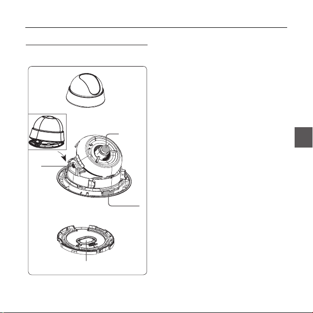
PART NAMES AND FUNCTIONS
Components of your camera ❖
1
3
2
LENS
4
6
7
Introduction
1.Cover dome: Covers the lens and main
body to protect them.
2.Main body: Includes a lens, a switch
board, a PCB board, screws, and such.
3.Locker: Used to open or close the Cover
dome. To open the cover dome, press the
locker.
4.Tilt fixing screw: Using this screw, the
slope of the lens can be adjusted and
fi xed.
5.Switch board: Includes two kinds of
control switches such as function switches
and phase-control switches. The board
has eight function switches in the middle
and two phase-control buttons on each
side of the function switch area.
6.Lock releaser: Push it outward and
rotate the main body in UNLOCK direction
when you want to remove the mount
bracket from the main body.
5
7.Ceiling mount opener: Remove it for
line connection to the ceiling when it is
installed on the ceiling.
English – 9
ENG
Page 10
Introduction
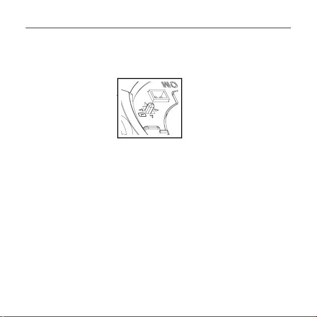
Setting switches❖
SETUP Switch
•
This switch is used to set the function or property. When this switch is pressed for at least 2 seconds, the
MAIN MENU appears.
ef
(Left/Right)
: By pressing this switch left or right, you can move left or right on the menu or change the
cd
(Up/Down) :
: When you press this switch in the menu, the selected function is confi rmed. To enter a submenu, press
this button.
10 – DIGITAL COLOR DOME CAMERA
displayed value.
By pressing this switch up or down, you can move up or down on the menu.
Page 11

Installation
BEFORE INSTALLATION
Before installing your camera, you have to read the following cautions.
You have to check whether the location (ceiling or wall) can bear fi ve times the weight of your camera.
•
Don’t let the cable to be caught in improper place or the electric line cover to be damaged. Otherwise it
•
may cause a breakdown or fi re.
When installing your camera, don’t allow any person to approach the installation site. If you have any
•
valuable things under the place, move them away.
INSTALLATION PROCEDURE
ENG
English – 11
Page 12

Installation
❶ Press the Locker button on the bottom of your camera and remove the Cover dome from the Main body
using the other hand. The Main body and Inner cover will be exposed to you.
❷To install and adjust your camera, you have to fi rst remove the Inner cover. To remove the Inner cover from
the Main body, push a long thin screwdriver into the narrow spot of the Wing locker and press it outward to
remove the cover.
❸Remove the Mount bracket from the Main body by rotating the Main body in the UNLOCK direction while
pushing the Lock releaser outward. If it is not easily done, rotate the Mount bracket in the LOCK direction
while holding small holes on the Mount bracket.
❹Fix the Mount bracket to the location (ceiling or wall) with supplied three screws.
Note :
The CAMERA FRONT sign on the Mount bracket should face the camera monitoring area.
–
❺When you install the Mount bracket on the ceiling, remove the Ceiling mount opener by pressing it hard to
connect the line attached on your camera through the hole in the ceiling. Otherwise, you can use the empty
space opposite to the CAMERA FRONT sign for line connection.
❻Now attach the Main body to the Mount bracket by rotating it in the LOCK direction after aligning the Groove
mark on the Main body with the wide groove around the CAMERA FRONT inlay.
❼ Finally attach the Cover dome to the Main body by pressing it until a “click” sound is heard after aligning the
bump inside the Cover dome with the Groove mark on the Main body.
12 – DIGITAL COLOR DOME CAMERA
Page 13

Installation
ADJUSTING THE CAMERA DIRECTION
When the camera is fi xed on the ceiling, you can adjust the camera viewing angle. You can rotate your camera
leftward or rightward (Panning), and can change the slope of your camera upward or downward (Tilting).
In case of panning, the rotation limit of your camera is set to 355 degree (100 degree clockwise and 255 degree
counterclockwise). The rotation is stopped by the Stopper inside of the camera. For panning control, fi rst
unfasten two screws located on the bottom and rotate in the direction you want, and then fasten them to fi x the
camera.
In case of tilting, you can change the slope of your camera from zero to 90 degree. However if the slope angle
is under 17 degree, you can encounter a partial image hide problem. To fi x the location after adjusting the tilting
angle, use the Tilt fi xing screws.
To adjust the focus and zoom of your camera, use the Zoom lever and Focus lever. When you install the
camera on the inclined ceiling or wall, you can rotate the camera lens to see a correct direction image.
Panning
Tilting
Lens rotation
English – 13
ENG
Page 14

How to use OSD Menu
USING ICONS IN THE MENU
(EXIT)
•
Exits the menu setting.
Before you exits the menu setting, select SAVE to
save your settings, or select QUIT to cancel.
(RET)
•
Returns to the previous menu.
(HOME)
•
Returns to the main menu.
(SAVE)
•
Used to save your settings of MASK AREA,
PRIVACY ZONE and more.
Once you save your settings, they will remain
even if you select QUIT in the menu.
•
(DEL)
Used to deletes your settings of MASK AREA,
PRIVACY ZONE and more.
Once you delete your settings, they will not be
restored even if you select QUIT in the menu.
14 – DIGITAL COLOR DOME CAMERA
MAIN MENU
ÃÃMAIN MENUÃÃ
PROFILE
CAMERA SET
INTELLIGENCE
PRIVACY ZONE
OTHER SET
SYSTEM INFO
LANGUAGE
PROFILE
•
You can set a mode according to the camera
installation conditions.
CAMERA SET
•
Confi gure Camera related functions and data.
INTELLIGENCE
•
You can confi gure the settings of motion
detection, tracking and more.
PRIVACY ZONE
•
You can confi gure the privacy related settings.
OTHER SET
•
You can confi gure for Factory Defaults, and more.
SYSTEM INFO.
•
Displays the system information including the
camera version and communication settings.
LANGUAGE
•
Select a preferred one from the supported
languages.
Page 15
PROFILE
e
Ã
BACKLIGHT
DAY/NIGHT
PROFILE
STANDARD
ITS
GAMING
CUSTOM
How to use OSD Menu
f
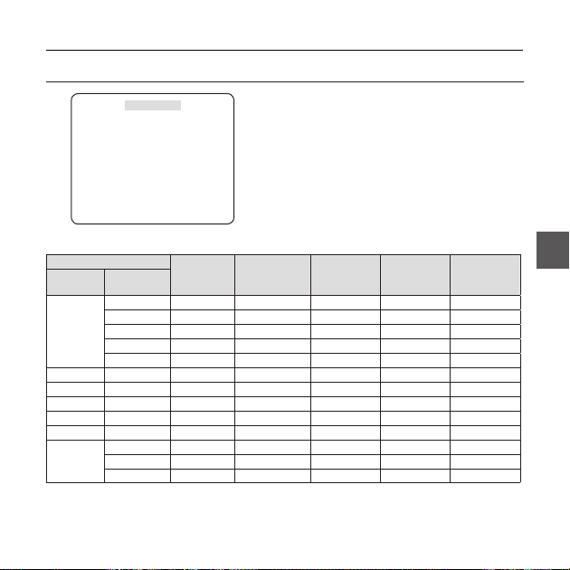
In the PROFILE menu, you can confi gure the following camera settings at once.
CAMERA SET Menu
Previous
MOTION (F.FAST)--- (F.FAST)--- NORM (F.FAST)--- SLOW
SHUTTER OFF AUTO1/250 OFF OFF OFF
SENS-UP AUTOx4 AUTOx2 AUTOx4 AUTOx4 AUTOx4
DAY/NIGHT AUTO AUTO DAY AUTO DAY
Sub-menus
Menu
IRIS ELC ELC ELC ELC ELC ELC
ALC - - - - -
BACKLIGHT OFF OFF BACKLIGHT OFF OFF
DNR MID MID MID MID MID
XDR MID MID MID MID MID
NIGHT-- ---
STANDARD ITS BACKLIGHT DAY/NIGHT GAMING
LENSDCDC DCDCDC
LEVEL 0 0 0 0 0
BURST OFF ON OFF OFF OFF
English – 15
ENG
Page 16

How to use OSD Menu
CAMERA SET Menu
Previous
WHITE BAL DAY DAY/NIGHT DAY DAY/NIGHT DAY
❖
Sub-menus
Menu
DAY -- ---
NIGHT-- ---
BRIGHTNESS
DETAIL 2 2 2 2 2
ITS
It will be set automatically so you can easily check the traffi c conditions.
❖
BACKLIGHT
It will be set automatically so you can distinguish the object from the background in a severe backlighting scene.
DAY/NIGHT
❖
It will be set automatically so it optimizes to the day or night conditions, respectively.
GAMING
❖
It will be set automatically to help you take a picture in a regular indoor lighting condition.
16 – DIGITAL COLOR DOME CAMERA
STANDARD ITS BACKLIGHT DAY/NIGHT GAMING
MODE ATW2 ATW1 ATW1 ATW1 ATW1
RED00 000
BLUE 0 0 0 0 0
User setting
allowed
MODE OFF ATW2 OFF ATW2 OFF
User setting
RED
allowed
User setting
BLUE
allowed
MID
User setting
allowed
User setting
0
0
allowed
User setting
allowed
MID
User setting
allowed
User setting
0
0
allowed
User setting
allowed
Page 17
CAMERA SETUP
eCAMERA SETf
CAMERA ID OFF
IRIS ELC
MOTION (F.FAST)--DNR MID
SHUTTER OFF
SENS-UP AUTO X4
FLICKERLESS (OFF
XDR MID
DAY/NIGHT AUTO
WHITE BAL
DIGITAL ZOOM
DETAIL [2]
V-SYNC (INT)--AGC COLOR SUP
REVERSE H/V
POSI/NEGA +
PIP OFF
DIS OFF
d
c
OFF
LOW
d
c
How to use OSD Menu
Setup the general functions of zoom camera module.
Use the
cdef
switch to select a menu item.
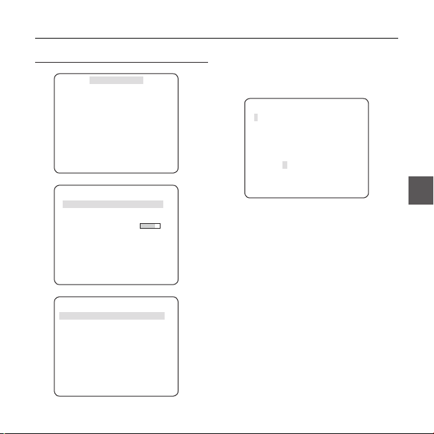
CAMERA ID [OFF, ON]
❖
CAMERA ID
ABCDEFGHIJKLMNOPQRSTUVWXYZ0
123456789 :?-+*()/
SP
ffee
SP LOCATION
CAMERA-1..................
...........................
The CAMERA ID menu is used for you to assign
a unique name to a camera. If you press the
SETUP switch with the CAMERA ID menu
selected, you will see the appropriate screen.
You can enter up to 54 alphanumeric or
special characters for the CAMERA ID. Select
LOCATION and press the SETUP switch to
move the display position of the CAMERA ID.
❖
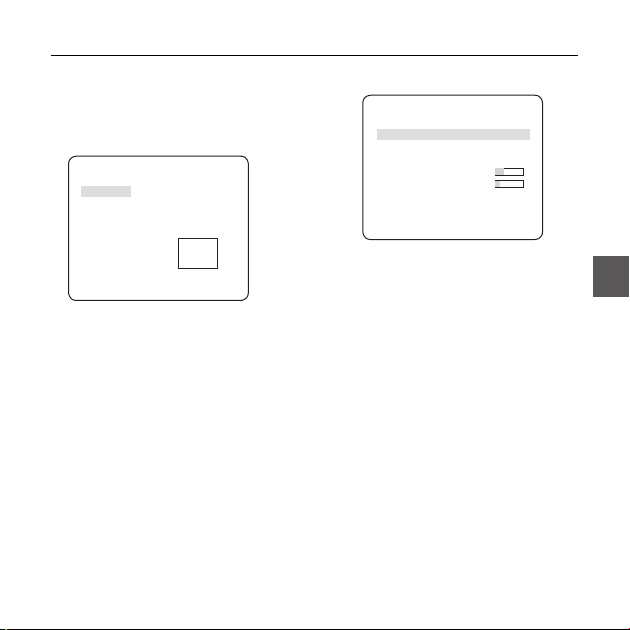
IRIS [ELC]
The IRIS menu is used if you want to adjust the
intensity of radiation incoming to the camera.
•
ELC (Electronic Light Control)
①
If you press the SETUP switch when the ELC
submenu is selected, the corresponding screen
English – 17
ENG
Page 18

How to use OSD Menu
appears. You can make the ELC (Electronic
Light Control) function active or not.
screen.
ELC
LEVEL [00]----I---BACKLIGHT OFF
② If you set the BACKLIGHT option to BLC,
you will see a menu where you can set the
BLC area.
you can set the desired BLC zone by defi ning
the size and location.
LEVEL [00]----I---BACKLIGHT BLC
AREA USER
<SIZE>
<LOCATION>
ELC
appropriate
I
If you use an ordinary camera in a scene
with an intensive backlight, the object will be
displayed dark on the monitor affected by the
backlight. To solve this problem, you can use
the BLC(Back Light Compensation) function
to improve the sharpness of the image in
such a high contrast scene.
❖
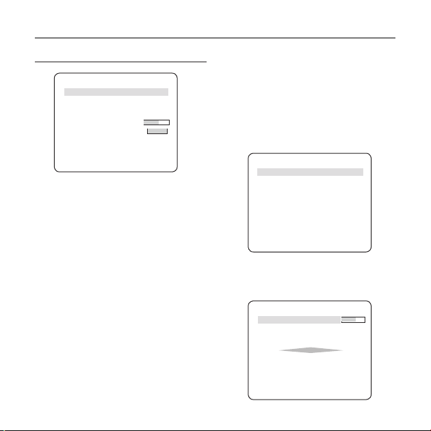
AGC
[OFF, VERY LOW, LOW, MID, HIGH, VERY
HIGH, USER, FIX]
The AGC (Auto Gain Control) menu is used to
set the AGC level of the camera. When the AGC
is active, the camera automatically increases the
sensitivity by amplifying the Video signal when
the strength of the signal falls below the normal
value.
If OFF or FIX mode is selected in the SENS-UP
menu, you can specify the AGC level.
If you press the SETUP switch with a USER
sub menu selected, you will see the appropriate
screen.
LEVEL [16]
AGC USER
18 – DIGITAL COLOR DOME CAMERA
Page 19

How to use OSD Menu
In USER mode, you can break down the level in
16 steps from VERY LOW to VERY HIGH to your
preference.
AGC FIX
LEVEL [01]
If you press the SETUP switch with a FIX sub
menu selected, you will see the appropriate screen.
As a fi xed value of the AGC gain is used in FIX
mode, you can select one of the 16 detailed levels
from VERY LOW to VERY HIGH before fi xing it.
FIX mode is not available if you set the
BACKLIGHT function to WDR.
Note :
If the DAY/NIGHT menu of the CAMERA SET is set to
–
AUTO, the AGC menu will be deactivated.
If FLICKERLESS is set to ON, the AGC FIX mode will be disabled.
–
MOTION
❖
The MOTION menu is used to adjust the strength
of the AGC level for a control of the camera motion.
This is available only if the SENS-UP menu is set
to AUTO.
You can select one from S.SLOW, SLOW, NORM,
FAST and F.FAST for the AGC level.
[S.SLOW, SLOW, NORM, FAST, F.FAST]
If you monitor a fast moving object in a low contrast
scene, select F.FAST while select S.SLOW for a
hardly moving object in the same lighting condition.
Note :
If the DAY/NIGHT menu of the CAMERA SET is set to
–
AUTO, the MOTION menu will be deactivated.
❖
DNR
You can confi gure the DNR (Digital Noise
Reduction) related settings.
Reduces the noise on the screen.
This is especially useful for a severely distorted
screen.
You can set the level if you set DNR to USER.
SENS-UP
❖
[OFF, AUTO X2, AUTO X4, AUTO X6, AUTO
X8, AUTO X12, AUTO X16, AUTO X24, AUTO
X32, AUTO X48, AUTO X64, AUTO X96, AUTO
X128, AUTO X256, AUTO X512]
XDR (eXtended Dynamic Range)
❖
[OFF, LOW, MID, HIGH]
Actively controls the gamma compensation in the
way it operates the ambient luminance contrast
in a certain pixel unit to determine the optimal
visibility.
Select one from OFF, LOW, MID and HIGH.
Closing to HIGH will increase the compensation
level.
[OFF,LOW,MID,HIGH, USER(1~16)]
English – 19
ENG
Page 20

How to use OSD Menu
DAY/NIGHT
❖
DAY
•
If set to DAY, it will be fi xed to DAY mode
regardless of the ambient conditions.
NIGHT
•
If set to NIGHT, it will be fi xed to Black-and-White
mode regardless of the ambient conditions.
If you press the SETUP switch with a NIGHT sub
menu selected, you will see a menu where you can
set Burst to OFF/ON.
If BURST is set to ON, the Burst signal will output
together with the black-and-white composite video
signal. If BURST is set to OFF, the Burst signal does
not output.
You can set the BURST option to OFF/ON, or
select to output the Burst signal in NIGHT mode.
AUTO
•
The camera will automatically switch between
DAY and NIGHT mode, according to the lighting
condition.
If you press the SETUP switch with an AUTObased sub menu selected, you will see the
appropriate screen.
20 – DIGITAL COLOR DOME CAMERA
[DAY,NIGHT,AUTO,EXT]
BURST OFF
DAYÆNIGHT
BRIGHTNESS MID
DWELL TIME 2S
NIGHTÆDAY
BRIGHTNESS MID
DWELL TIME 5S
MASK AREA 1 2
You can set the BURST option to OFF/ON, or
select to output the Burst signal in NIGHT mode.
The BRIGHTNESS of DAYÆNIGHT sets the
brightness degree of color to BW switching,
for which you can select from LOW, MID, and
HIGH. As you adjust it from HIGH to LOW, the
screen switches to black and white mode under
the darker situation.
DWELL TIME of DAYÆNIGHT sets the time to
maintain switched black and white mode.
The BRIGHTNESS of NIGHTÆDAY sets the
brightness degree of BW to color switching, for
which you can select from LOW, MID, and HIGH.
As you adjust it from HIGH to LOW, the screen
switches to color mode under the darker situation.
DWELL TIME of NIGHTÆDAY sets the time to
maintain switched color mode.
The MASK AREA menu is used to prevent
unintended mode switching or inability of
determining the switching due to existence of
AUTO
Page 21
high spot light source at night.
If you press the SETUP switch in item 1 or 2 of
the MASK AREA menu, you will see a menu
where you can specify an area to MASK.
MASK AREA
<SIZE>
<LOCATION>
You can specify MASK 1 and 2 simultaneously.
The MASK is only for determining the mode
switching, and any excessive bright area at night
will be excluded by the confi gured MASK.
Note :
–
If BACKLIGHT is set to BLC, the MASK AREA function will
be deactivated.
WHITE BAL [DAY/NIGHT]
❖
If you want to adjust the color scheme, use the
WHITE BALANCE function.
DAY
•
In DAY mode, you can set the color values of
RED and BLUE. The screen will be displayed in
How to use OSD Menu
colors according to your settings.
WHITE BAL
DAY/NIGHT DAY
MODE AWC
RED [00]----I--- BLUE [00]----I--- R-GAIN [0248]
B-GAIN [0247]
Note :
You can set the values of R-GAIN and B-GAIN only in
–
AWC mode.
•
NIGHT
Use the NIGHT mode if you want to set the white
balance differently according to the ambient
luminance.
If the NIGHT mode is set to OFF, the white
balance will always operate as set in DAY mode;
if not to OFF, the camera will switch to as set in
DAY/NIGHT mode according to the brightness.
In NIGHT mode, you can set the values of RED,
BLUE and BRIGHTNESS. The screen will be
displayed in colors according to your settings.
English – 21
ENG
Page 22

How to use OSD Menu
R-GAIN/B-GAIN : Enables you to set the current
WHITE BAL
DAY/NIGHT NIGHT
BRIGHTNESS MID
MODE AWC
RED [00]----I--- BLUE [00]----I--- R-GAIN [0248]
B-GAIN [0247]
Note :
You can set the values of R-GAIN and B-GAIN only in
–
AWC mode.
If AGC is set to OFF or FIX, you can not access the
–
NIGHT menu.
–
For adjusting the white balance, the following
5 modes are provided:
•
ATW1(Auto Tracing White Balance mode
1): The camera can automatically adjust the
color temperature in real time, according to
the ambient conditions. The color temperature
ranges from approx. 2500K to 9300K.
•
ATW2: The color temperature ranges from
approx. 2,000K to 10,000K.
•
AWC ( Auto White Balance Control): If you
press the SETUP switch in the appropriate item
position, Auto White Balance will perform once.
•
3200K : Set color temperature to 3200K
•
5600K : Set color temperature to 5600K
–
RED : Adjusts the strength of the red color.
BLUE : Adjusts the strength of the blue color.
–
22 – DIGITAL COLOR DOME CAMERA
–
color temperature manually.
BRIGHTNESS : Select a brightness level in
–
switching from setting in DAY mode to setting in
NIGHT mode.
DIGITAL ZOOM [ON/OFF]
❖
You can set the digital zoom factor and position.
If you press the SETUP switch with the DIGITAL
ZOOM function set to ON, you will see the
appropriate screen.
When the zoom factor and position are defi ned,
the digital zoom function will operate.
RATIO [X1.0]
< LOCATION >
-
LOCATION : If you press the SETUP switch in the
condition where the image is enlarged as much as the
ratio setting, you can watch an invisible area of the
effective screen as well using the
Note :
If the digital zoom factor is set to larger than 1x, the FENCE
–
function will be deactivated.
The DIGITAL ZOOM function enlarges the pixel itself, which can
cause deterioration of the quality.
DIGITAL ZOOM
cdef
switch.
Page 23

How to use OSD Menu
DETAIL [0~3]
❖
Controls the horizontal or vertical distinction.
V-SYNC [INT, LINE]
❖
Select the vertical sync mode for INT or LINE.
If you select INT, the camera will use the internal
synchronization.
If selecting LINE, the camera will use the external
power source frequency for the synchronization.
You can adjust the LL-PHASE.
Note :
Use of DC 12V will fi x V-SYNC to INT, which can not be
–
changed.
AGC COLOR SUP [LOW , MID, HIGH]
❖
Adjust the color scheme according to the AGC
value.
❖
REVERSE [OFF, H, V, H/V]
Mirrors video signals horizontally, vertically, or
both.
POSI/NEGA [+, -]
❖
Output as it is or mirror the video brightness
signal.
PIP [OFF, ON]
❖
Displays a sub image together with the main
image on the same screen using the Picture In
Picture function.
Note :
If more than one privacy zone is set and the PRIVACY
–
SET is set to ON, the PIP function will be deactivated.
If the INTELLIGENCE function is set to FENCE mode, the
–
PIP menu will be deactivated.
DIS [OFF, ON]
❖
Digital Image Stabilization will set the anti-shake
compensation.
Note :
If you set DIS to ON, the compensation area will be
–
enlarged as set in the digital zoom factor.
If you set the digital zoom factor to greater than the
enlarged zoom factor for the compensation, the DIS
function will be deactivated.
English – 23
ENG
Page 24
How to use OSD Menu
FENCE
INTELLIGENCE
eINTELLIGENCEf
MOTION OFF
ADVANCED OFF
MASK AREA
DISPLAY ON
SENSITIVITY [4]
RESOLUTION [5]
You can set the motion detection and tracking in the
INTELLIGENCE menu.
MOTION
❖
TRACKING
•
Detects and tracks a moving object.
DETECTION
•
Detects a moving object.
Note :
If it is set to DETECTION, you can not set such functions as
–
FIXED/MOVED and FENCE in the ADVANCED menu.
ADVANCED
❖
Detects a motion of an object and displays an
image of any moving object before tracking the
moving route.
24 – DIGITAL COLOR DOME CAMERA
1 2 3 4
[OFF,TRACKING,DETECTION]
[OFF, FIXED/MOVED, FENCE]
•
This is to detect if a moving object passes
through the specifi ed LINE or AREA.
In a condition where a moving object is detected
in an analysis of the previous and current frames
whose movement overlaps a certain area, the
system displays “PASS” if the object’s center line
passes through the line while it displays “ENTER” or
“EXIT” if the center point passes through the area.
LINE OFF
AREA OFF
You can set the position and detection direction of the
LINE, and the size and position of the AREA.
- How to set the line
PIXEL LEVEL [4]
<POINT>
DIRECTION §¨
FENCE
LINE
Page 25
How to use OSD Menu
① If you press the SETUP switch with the LINE
option set to ON, you can specify the position
and detection direction of the line.
② If you change the PIXEL LEVEL for setting
the position, specify the pixel that moves by a
single pressure of the
In <POINT>, you can specify the fi rst position of
③
the line by pressing the SETUP switch once, and
the second position by pressing the switch again.
Use the
cdef
position.
Set each position of the two points and press the
SETUP switch to complete the positioning.
④
If you change the DIRECTION, you can specify
the detection direction. The detection direction
based on the defi ned two points will be
displayed on the screen.
- How to set the area
PIXEL LEVEL [4]
<SIZE>
<LOCATION>
① If you press the SETUP switch with the AREA
option set to ON, you can specify the position
cdef
switch to specify the
AREA
switch.
and size of the area.
② If you change the PIXEL LEVEL for setting
the position, specify the pixel that moves by a
single pressure of the
In <SIZE>, press the SETUP switch and use
③
the
cdef
Press the SETUP switch again to complete the
sizing.
④
In <LOCATION>, press the SETUP switch and
use the
cdef
Press the SETUP switch again to complete
the positioning.
Note :
If you set the LINE of the FENCE to ON, PRIVACY 12 will
–
not be available.
Functions of FENCE, PIP, DIS and DIGITAL ZOOM (if the
digital zoom factor is set to larger than 1x) can not be
used simultaneously.
In the boundary of the defi ned AREA and LINE, a FENCE
–
detection error may occur if two or more moving objects
overlap with each other or one object separates in
multiple directions.
FIXED/MOVED
–
If an object on the screen suddenly disappears or
an object comes out of nowhere and stays for a
certain time, the area will be displayed.
A detection (FIXED/MOVED) error may occur if :
- multiple motions occur continuously in random
directions
- a fi xed object moves in one position continuously
cdef
switch.
switch to adjust the size.
switch to specify the position.
English – 25
ENG
Page 26

How to use OSD Menu
- a second object screens the fi rst moving object
MASK AREA [1~4]
❖
Specify a detection exception area to mask.
Select a mask number and specify the size and
position.
MASK AREA
<SIZE>
<LOCATION>
❖
DISPLAY [ON, OFF]
With the DISPLAY option set to ON, a motion or
a set ADVANCED function will be displayed on
the screen, if detected.
❖
SENSITIVITY [1~7]
Set the sensitivity of the motion detection.
RESOLUTION [1~5]
❖
If setting it to high, the camera can detect even a
trivial movement of the target.
26 – DIGITAL COLOR DOME CAMERA
PRIVACY ZONE SETUP
1 2 3 4 5 6
7 8 9 10 11
PRIVACY SET ON
STYLE
The PRIVACY function will protect your privacy by
screening the privacy area that you have specifi ed
during monitoring. You can specify up to 12 privacy
zones.
If you set the PRIVACY SET to ON, your PRIVACY
ZONE settings will be applied.
You can change the style to adjust the mosaic size
and color of the PRIVACY ZONE.
1 2 3 4 5 6
7 8 9 10 11
PRIVACY SET ON
STYLE COLOR
Y-LEVEL [128]
RED [128]
BLUE [128]
ePRIVACY ZONEf
MOSAIC1
ePRIVACY ZONEf
12
12
Page 27

How to use OSD Menu
Use the
cdef
PRIVACY 1 through 12.
Select one from PRIVACY 1~12 and press the
SETUP switch to confi rm your setting. You can
specify a pixel that moves as you change the PIXEL
LEVEL to set the position.
PRIVACY ZONE SET1
PIXEL LEVEL [4]
<POINT>
<POSITION>
- How to set the point
You can set each position of the 4 points.
① If you press the SETUP switch in <POINT>,
you will see the points available in the
PRIVACY ZONE. Each time you press the
SETUP switch, the points available will move.
② Use the
of each point. Set each position of the four
points and press the SETUP switch to
complete the positioning.
- How to set the position
You can move the position of the overall area.
switch to select one from
cdef
switch to set the position
① By pressing the SETUP switch in
<POSITION>, you can move the overall
position of the privacy zone.
cdef
② Use the
position and press the SETUP switch to
confi rm it.
Note :
If more than one PRIVACY ZONE is specifi ed and the
–
PRIVACY SET is set to ON, the PIP function will be
deactivated.
If the 12th PRIVACY ZONE is specifi ed, the LINE function
–
of FENCE will be deactivated.
switch to move the
English – 27
ENG
Page 28

How to use OSD Menu
OTHER SET
eOTHER SETf
FACTORY DEFAULTS
OSD COLOR BW
SYSTEM INFORMATION
TYPE 3_FIX_NOR_P
SERIAL NO.
CAMERA VER. 0.50_090101
eSYSTEM INFOf
000000000000000
FACTORY DEFAULTS
❖
All the settings will be restored to the factory
default.
However, the settings of PROTOCOL, BAUD
RATE, ADDRESS and LANGUAGE will not be
restored to the default.
OSD COLOR [BW, R/G/B]
❖
You can set the OSD(On-screen Display) color to
COLOR or B/W.
28 – DIGITAL COLOR DOME CAMERA
You can check the system information such as
SERIAL NO and CAMERA VER.
LANGUAGE
eLANGUAGEf
ÃENGLISH
PУCCKNЙ
POLSKI
ČESKY
TÜRKÇE
The camera supports 5 different languages.
Select a preferred language.
Page 29

Initial Confi guration Table
❖
Camera Confi guration
•
CAMERA ID OFF
IRIS ALC
AGC VERY HIGH
MOTION (F.FAST)
DNR MID
SHUTTER OFF
SENS-UP
AUTO x4
FLICKERLESS (OFF)--XDR MID
DAY/NIGHT AUTO
DIGITAL ZOOM OFF
DETAIL [2]
AGC COLOR SUP MID
REVERSE H/V
POSI/NEGA +
PIP OFF
DIS OFF
V-SYNC INT
How to use OSD Menu
ENG
English – 29
Page 30
Specifi cations
SPECIFICATIONS
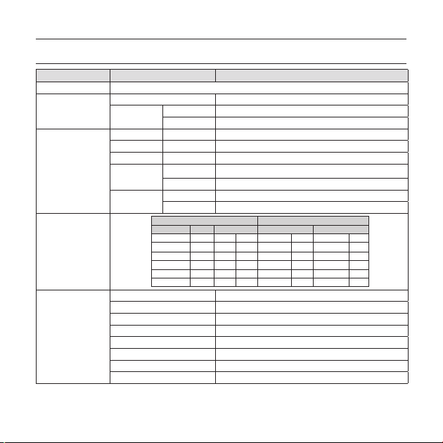
Items Sub-items SCC-B5331N/SCC-5333N/SCC-B5335N
Camera Type
Image
Scanning
Min. Scene
Illumination
Functions
Device 1/3” Super-HAD PS CCD
Pixels
System Interlace/Progressive
Scanning Line 525 lines
Frame 30frame/1sec
Horizontal
Frequency
Vertical
Frequency
Sens-up F No. Level DAY NIGHT
512 times 1.2 50 IRE 0.002 Lux 0.002 Lux
512 times 1.2 30 IRE 0.0012 Lux 0.0012 Lux
512 times 1.2 15 IRE 0.0006 Lux 0.0006 Lux
Number of Privacy Zone 12 (Polygonal Method)
Day/Night DAY/NIGHT/AUTO/EXT
Motion Detection OFF/Tracking/Detection
eXtended Dynamic Range(XDR) Off/On (Level Setting)
D-Zoom x1 ~ x16 (x0.1 STEP)
PIP Off/On
High Speed Shutter 1/60 ~ 1/10Ksec (OSD)
Flickerless Off/On
30 – DIGITAL COLOR DOME CAMERA
CCTV Camera (WDR & DAY/NIGHT)
Total 811 x 508
Effective 768 x 494
Internal Mode 15,734 Hz
Line-lock Mode 15,750 Hz
Internal Mode 59.94 Hz
Line-lock Mode 60 Hz
Condition Min. Scene illumination
OFF 1.2 50 IRE 1 Lux 1 Lux
OFF 1.2 30 IRE 0.6 Lux 0.6 Lux
OFF 1.2 15 IRE 0.3 Lux 0.3 Lux
Page 31

Specifi cations
Items Sub-items SCC-B5331N/SCC-5333N/SCC-B5335N
Sens-Up x2 ~ x512
AGC Off/On (Max.Level Setting)
Line Lock Off/On (Phase Control)
Camera ID Off/On (Max.54ea/2Line)
White Balance ATW1/ATW2/AWC/3200K/5600K
Digital Noise Reduction(DNR) Off/On (Adaptive 3D+2D)
Resolution
Video Output
S/N Ratio
Lens
PAN
TILT
Remote
Control
Environmental
Conditions
Power
Physical
Specifi cation
Digital Image Stabilization(DIS)
Intelligent Video Fixed/Moved, Fence,Off
Etc. Function Detail, Reverse(H/V), Posi/Nega
Horizontal 600 TV Lines
Vertical 350 TV Lines
- VBS 1.0Vp-p, 75 Ω
S/N Ratio Approx. 52dB
Lens Drive Type
Range
Range 0 ~ 90°
Coaxitron (Data On Coax cable) Yes (with SCX-RD100)
Operating Temperature -10˚C ~ +50˚C
Humidity Less than 90%
Power Requirement
Power Consumption 2.1W
Dimensions (Ø x H) 128(Ø) x 91(H)mm
Weight 330g
Color White
ELC
SCC-B5331 : f=3.8mm F 2.0
SCC-B5333 : f=3.0mm F2.0
SCC-B5335 : f=8.0mm F2.0
0 ~ 340°(220° in CW(Clockwise) direction,
120° in CCW (Counterclockwise) direction)
Off/On
AC24V ± 10%(60Hz ± 0.3Hz)
DC12V ± 10%
English – 31
ENG
Page 32

Specifi cations
Items Sub-items SCC-B5331P/SCC-B5333P/SCC-B5335P
Camera Type
Image
Scanning
Min. Scene
Illumination
Functions
Device 1/3” Super-HAD PS CCD
Pixels
System Interlace/Progressive
Scanning Line 625 lines
Frame 25frame/1sec
Horizontal
Frequency
Vertical
Frequency
Sens-up F No. Level DAY NIGHT
512 times 1.2 50 IRE 0.002 Lux 0.002 Lux
512 times 1.2 30 IRE 0.0012 Lux 0.0012 Lux
512 times 1.2 15 IRE 0.0006 Lux 0.0006 Lux
Number of Privacy Zone 12 (Polygonal Method)
Day/Night DAY/NIGHT/AUTO/EXT
Motion Detection OFF/Tracking/Detection
eXtended Dynamic Range(XDR) Off/On (Level Setting)
D-Zoom Max. x16
PIP Off/On
Sens-Up x2 ~ x512
BLC Off/On (Area Setting)
32 – DIGITAL COLOR DOME CAMERA
CCTV Camera (WDR & DAY/NIGHT)
Total 795 x 596
Effective 752 x 582
Internal Mode 15,625 Hz
Line-lock Mode 15,625 Hz
Internal Mode 50 Hz
Line-lock Mode 50 Hz
Condition Min. Scene illumination
OFF 1.2 50 IRE 1 Lux 1 Lux
OFF 1.2 30 IRE 0.6 Lux 0.6 Lux
OFF 1.2 15 IRE 0.3 Lux 0.3 Lux
Page 33

Specifi cations
Items Sub-items SCC-B5331P/SCC-B5333P/SCC-B5335P
AGC Off/On (Max.Level Setting)
Line Lock Off/On (Phase Control)
Camera ID Off/On (Max.54ea/2Line)
White Balance ATW1/ATW2/AWC/3200K/5600K
Digital Noise Reduction(DNR) Off/On (Adaptive 3D+2D)
Resolution
Video Output
S/N Ratio
Lens
PAN
TILT
Remote
Control
Environmental
Conditions
Power
Physical
Specifi cation
Digital Image Stabilization(DIS)
Intelligent Video Fixed/Moved, Fence, Off
Etc. Function Detail, Reverse(H/V), Posi/Nega
Horizontal 600 TV Lines
Vertical 350 TV Lines
- VBS 1.0Vp-p, 75 Ω
S/N Ratio Approx. 52dB
Lens Drive Type
Range
Range 0 ~ 90°
Coaxitron (Data On Coax cable) Yes (with SCX-RD100)
Operating Temperature -10˚C ~ +50˚C
Humidity Less than 90%
Power Requirement
Power Consumption 2.1W
Dimensions (Ø x H) 128(Ø) x 91(H)mm
Weight 330g
Color White
ELC
SCC-B5331 : f=3.8mm F 2.0
SCC-B5333 : f=3.0mm F2.0
SCC-B5335 : f=8.0mm F2.0
0 ~ 340°(220° in CW(Clockwise) direction,
120° in CCW (Counterclockwise) direction)
Off/On
AC24V ± 10%(50Hz±0.3Hz)
DC12V ± 10%
English – 33
ENG
Page 34

Correct Disposal of This Product
(Applicable in the European Union and other European countries with separate collection systems)
This marking on the product, accessories or literature indicates that the product and its electronic accessories
(e.g. charger, headset, USB cable) should not be disposed of with other household waste at the end of their
working life. To prevent possible harm to the environment or human health from uncontrolled waste disposal,
please separate these items from other types of waste and recycle them responsibly to promote the sustainable
reuse of material resources.
Household users should contact either the retailer where they purchased this product, or their local government
office, for details of where and how they can take these items for environmentally safe recycling.
Business users should contact their supplier and check the terms and conditions of the purchase contract.
This product and its electronic accessories should not be mixed with other commercial wastes for disposal.
(Waste Electrical & Electronic Equipment)
Page 35

SCC-B5331
SCC-B5333
SCC-B5335
ЦВЕТНАЯ ЦИФРОВАЯ
КУПОЛЬНАЯ КАМЕРА
руководство пользователя
удивительные возможности
Благодарим Вас за приобретение данного продукта компании Samsung.
Для получения более полного обслуживания
зарегистрируйте свое устройство по адресу:
www.samsungsecurity.com
RUS
Page 36

Меры предосторожности
ВНИМАНИЕ
ОПАСНОСТЬ ПОРАЖЕНИЯ ЭЛЕКТРИЧЕСКИМ
ТОКОМ! НЕ ОТКРЫВАТЬ!
ВНИМАНИЕ: ВО ИЗБЕЖАНИЕ ПОРАЖЕНИЯ ЭЛЕКТРИЧЕСКИМ ТОКОМ НЕ ОТКРЫВАЙТЕ КРЫШКУ (ИЛИ ЗАДНЮЮ ПАНЕЛЬ)
УСТРОЙСТВА. ВНУТРИ ОТСУТСТВУЮТ ДЕТАЛИ, ОБСЛУЖИВАНИЕ КОТОРЫХ МОЖЕТ ВЫПОЛНЯТЬ ПОЛЬЗОВАТЕЛЬ.
ОБСЛУЖИВАНИЕ ДОЛЖНО ВЫПОЛНЯТЬСЯ КВАЛИФИЦИРОВАННЫМИ СПЕЦИАЛИСТАМИ.
Этот символ обозначает, что внутри устройства имеется опасное напряжение,
которое может привести к поражению электрическим током.
Этот символ указывает, что в документации на изделие имеется важная инструкция
по его использованию или обслуживанию.
ПРЕДУПРЕЖДЕНИЕ
•
Во избежание повреждений, следствием которых может быть пожар или поражение
электрическим током, не допускайте попадания данного изделия под дождь или в условия
высокой влажности.
ПРЕДУПРЕЖДЕНИЕ
Пользуйтесь только стандартным блоком питания, который указан в листе спецификаций.
1.
Использование любого другого блока питания может привести к пожару, поражению
электрическим током или к повреждению изделия.
Неправильное подключение блока питания или замена батареи может привести к взрыву,
2.
пожару, поражению электрическим током или к повреждению изделия.
Не подключайте несколько видеокамер к одному блоку питания. Превышение нагрузочной
3.
способности блока питания может привести к его перегреву или к пожару.
2 – ЦВЕТНАЯ ЦИФРОВАЯ КУПОЛЬНАЯ КАМЕРА
Page 37

Меры предосторожности
Надежно вставьте вилку сетевого шнура в розетку сети переменного тока. Ненадежное
4.
подключение может привести к пожару.
При установке видеокамеры закрепите ее прочно и надежно. Падение видеокамеры может
5.
привести к травме.
6.
Не кладите сверху на видеокамеру токопроводящие предметы (например, отвертки,
монеты и другие металлические предметы) и не ставьте на нее наполненные водой сосуды.
Невыполнение этих требований может привести к пожару, поражению электрическим
током или к травмам в результате падения этих предметов.
7.
Не устанавливайте изделие во влажных, запыленных или покрытых копотью помещениях.
Невыполнение этого требования может привести к пожару или к поражению электрическим
током.
8.
Если вы почувствуете необычный запах или обнаружите дым, выходящий из изделия,
прекратите эксплуатацию. В этом случае следует немедленно отсоединить изделие от
источника питания и связаться с сервисным центром. Продолжение эксплуатации изделия в
таком состоянии может привести к пожару или к поражению электрическим током.
9.
При обнаружении неисправности в изделии свяжитесь с ближайшим сервисным центром.
Никогда не разбирайте данное изделие и не вносите изменений в его конструкцию.
(Компания SAMSUNG не несет ответственности за проблемы, возникшие в результате
внесения изменений в конструкцию изделия или попыток самостоятельно выполнить
ремонт изделия).
10.
При чистке изделия не разбрызгивайте на него воду. Это может привести к пожару или к
поражению электрическим током
Pyccкий – 3
RUS
Page 38

Меры предосторожности
ВНИМАНИЕ
Не роняйте на изделие никакие предметы и не ударяйте по нему. Не устанавливайте
1.
изделие в местах с сильной вибрацией или вблизи источников магнитного поля.
Не устанавливайте изделие в помещениях с высокой температурой (выше 50°С),
2.
пониженной температурой (ниже -10°С) или высокой влажностью. Это может привести к
возгоранию или поражению электрическим током.
Если вы хотите переместить ранее установленное изделие на новое место, отключите перед
3.
этим питание изделия.
Во время грозы отсоедините шнур питания видеокамеры от розетки сети переменного тока.
4.
Невыполнение этого требования может привести к пожару или к повреждению изделия.
Устанавливайте изделие так, чтобы на него не падал прямой солнечный свет и чтобы рядом
5.
не было источников, излучающих тепло. Это может привести к пожару.
Изделие должно устанавливаться в помещении с хорошей вентиляцией.
6.
Избегайте направлять видеокамеру прямо на очень яркие объекты, например, на солнце,
7.
так как это может привести к повреждению матрицы ПЗС, формирующей изображение.
Изделие должно быть защищено от воздействия капель или брызг воды и на него нельзя
8.
помещать наполненные водой сосуды, например, вазы с цветами.
Вилка сетевого шнура используется в качестве отсоединяющего от питания устройства и к
9.
ней всегда должен быть обеспечен легкий доступ.
4 – ЦВЕТНАЯ ЦИФРОВАЯ КУПОЛЬНАЯ КАМЕРА
Page 39

Важные инструкции по технике безопасности
1.
Прочтите эти правила.
2.
Сохраните эти правила.
3.
Принимайте во внимание все предупреждения.
4.
Следуйте всем правилам.
5.
Не используйте изделие вблизи воды.
6.
Чистите изделие только сухой салфеткой.
7.
Не загораживайте никакие вентиляционные отверстия. Выполните установку изделия в соответствии с
инструкциями изготовителя.
8.
Не устанавливайте изделие рядом с источниками тепла, такими, как радиаторы, решетки системы
отопления, или другими устройствами, которые генерируют тепло (включая усилители).
9.
В целях безопасности не отказывайтесь от использования вилок поляризованного или заземляющего
типа. Вилка поляризованного типа имеет два ножевых контакта, один из которых шире другого.
Вилка заземляющего типа имеет два контакта и третий заземляющий штырь. Широкое лезвие третьего
заземляющего штыря предусмотрено для вашей безопасности. Если вилка поставляемого вместе с
аппаратом шнура питания не подходит для вашей розетки, попросите опытного электрика заменить
старую розетку.
Не наступайте на шнур питания и не допускайте его защемления, особенно вблизи от штепсельной
10.
вилки, в месте подключения к розетке и там, где шнур выходит из изделия.
Пользуйтесь только теми приспособлениями/ принадлежностями, которые
11.
рекомендованы изготовителем.
Используйте изделие только с тележкой, кронштейном, штативом, держателем или
12.
подставкой, предусмотренными изготовителем или поставляемыми в комплекте с
изделием.
Перед перемещением изделия отсоедините его от электросети. Если используется
13.
тележка, соблюдайте осторожность при перемещении тележки с изделием, чтобы
избежать повреждения изделия или травмы при опрокидывании.
14.
Все работы, связанные с техническим обслуживанием изделия, должны выполняться
квалифицированными специалистами по техническому обслуживанию. Обслуживание изделия
требуется выполнять, когда изделие получило какое-либо повреждение, например, был поврежден
его шнур питания или вилка шнура питания, внутрь изделия попала жидкость или посторонние
предметы, изделие подверглось воздействию дождя или влаги, изделие не работает должным
образом, а также после падения изделия.
Pyccкий – 5
RUS
Page 40

Содержание
Введение
Функции 7
Устройство и принадлежности 8
Компоненты видеокамеры и их назначение 9
Установка
Перед установкой 12
Процедура установки 12
Регулировка направления объектива камеры 14
Использование экранного меню
Использование значков в меню 15
Ochobhoe mehю 15
Пpoфиль 16
Hactp. кamepы 18
C-ma otcлeж-я 25
Настройка зоны конфиденциальности 28
Другой тв 29
Иhф. o cиcteme 30
ЯЗЫК 30
Технические характеристики
Технические характеристики 31
6 – ЦВЕТНАЯ ЦИФРОВАЯ КУПОЛЬНАЯ КАМЕРА
Page 41

Введение
ФУНКЦИИ
Высокое разрешение
❖
Высокое разрешение видеокамеры 600 телевизионных линий обеспечивается с помощью использования
•
полностью цифровой обработки изображения и применения современных цифровых алгоритмов и технологий.
❖
Интеллектуальное обнаружение и отслеживание движения
•
Эта интеллектуальная функция позволяет автоматически обнаруживать движение объекта. Вы можете
создавать виртуальный барьер, при прохождении объектов через которую, будет отображаться сигнал
тревоги.
❖
XDR (расширенный динамический диапазон)
•
Активное управление параметром гамма-коррекции, характеризующимся возможностью корректировки
внешнего яркостного контраста в определенном пикселе для определения оптимальной видимости.
❖
Высокая чувствительность
•
Данная функция позволяет создавать изображения с высокой чувствительностью с помощью новейшей
камеры SONY Super-HAD IT CCD.
❖
Работа при низкой освещенности
•
В видеокамере имеется функция работы при низкой освещенности и функция День/Ночь, которые
базируются на технологии цифровой обработки сигнала и позволяют использовать видеокамеру при очень
низкой внешней освещенности.
❖
Превосходная компенсации встречной засветки
•
Если позади объекта находится источник яркого света или солнце, то данная видеокамера выполняет
компенсацию затемнения изображения, вызванного встречной засветкой, и обеспечивает получение
нормального изображения.
❖
Цифровая синхронизация развертки с частотой сети переменного тока
•
В данной видеокамере используется полностью цифровая синхронизация развертки от сети переменного
тока, которая непосредственно подстраивает синхронизацию кадровой развертки к частоте сети и
улучшает управляемость и надежность видеокамеры.
❖
Настройка выходного сигнала
•
Имеется возможность выполнить следующие настройки выходного видеосигнала: перевернуть
изображение (относительно горизонтальной оси, вертикальной оси, или обеих осей), задать зону для
защиты от вторжения в частную жизнь, отрегулировать четкость изображения по горизонтали и по
вертикали, а также использовать цифровое увеличение изображения.
Pyccкий – 7
RUS
Page 42

Введение
Экранное меню
❖
Экранное меню предназначено для отображения состояния камеры и для настройки функций в
•
диалоговом режиме.
❖
Связь через коаксиальный кабель
•
Это функция дистанционного управления, благодаря которой управляющие сигналы подаются по коаксиальному
кабелю (предназначен для передачи видеосигнала). В случае установки или ремонта данная функция позволяет
управлять контроллером связи (приобретается дополнительно) без использования дополнительных кабелей.
УСТРОЙСТВО И ПРИНАДЛЕЖНОСТИ
УСТРОЙСТВО И ПРИНАДЛЕЖНОСТИ
❖
Основное устройство
•
Видеокамера
Принадлежности
•
Кабель для контрольного монитора
Примечание :
Кабель для контрольного монитора используется для проверки работоспособности видеокамеры посредством ее
–
подключения к переносному дисплею. Если вам действительно требуется подключить камеру к видеоконтрольному
устройству для мониторинга поступающего с нее изображения, используйте кабель с разъемами BNC (миниатюрными
байонетными соединителями).
Крепежный винт
8 – ЦВЕТНАЯ ЦИФРОВАЯ КУПОЛЬНАЯ КАМЕРА
Руководство пользователя
Page 43

КОМПОНЕНТЫ ВИДЕОКАМЕРЫ И ИХ НАЗНАЧЕНИЕ
Компоненты камеры❖
1
1
3
2
Объектив
4
6
7
. Купольная крышка: Закрывает линзы и защищает их.
2. Корпус видеок амеры: В его состав входят объектив,
плата переключателей, печатная плата, винты и т.п.
3. Замок: Используется для того, чтобы открывать
или закрывать купольную крышку. Чтобы открыть
купольную крышку, нажмите на кнопку замка.
4. Винт фиксации наклона: С использованием этого
винта можно
зафиксировать его.
5. Плата переключателей: Включает два типа
переключателей управления – функциональные
переключатели и переключатели регулировки
фазы. В середине платы расположены восемь
функциональных переключателей, а с двух сторон
зоны функциональных переключателей расположены
две кнопки регулировки фазы синхронизации.
6. Разблокиратор замка: Надавите в сторону и
поверните основной корпус в сторону
UNLOCK (Разблокировать), если вы хотите отделить
крепежную скобу от основного корпуса.
7. Заглушка, удаляемая при монтаже на потолке:
5
Удалите для подсоединения кабелей при монтаже
видеокамеры на потолке.
отрегулировать наклон объектива и
Введение
RUS
надписи
Pyccкий – 9
Page 44

Введение
Установка переключателей❖
Переключатель SETUP (Настройка)
•
Этот выключатель используется для настройки функции или свойства. При нажатии этого
переключателя на 2 секунды или более отображается меню OCHOBHOE MEHЮ.
ef
(Влево/Вправ)
cd
(Вверх/Вниз) :
: При нажатии этого переключателя, когда отображается меню, выбранная функция
подтверждается. Нажмите эту кнопку для входа в подменю.
10 – ЦВЕТНАЯ ЦИФРОВАЯ КУПОЛЬНАЯ КАМЕРА
: Нажатием переключателя влево или вправо можно перемещаться в меню влево
или вправо или изменять отображаемое значение.
Нажатием переключателя вверх или вниз можно перемещаться по пунктам меню вверх
или вниз.
Page 45

Установка
ПЕРЕД УСТАНОВКОЙ
Перед установкой видеокамеры обязательно прочтите информацию о следующих мерах предосторожности:
Перед установкой убедитесь в том, что выбранная площадка для установки (на потолке или стене) надежно выдерживает
•
5-кратный вес видеокамеры.
Проверьте, что кабель не зажимается какими-либо предметами, и что его изоляционная оболочка не повреждена. Невыполнение
•
этого требования может привести к повреждению видеокамеры или к пожару.
Удалите с места установки видеокамеры посторонних людей, так как во время выполнения монтажа видеокамеры на них могут
•
упасть тяжелые предметы. Перед началом установки видеокамеры уберите с места установки ценное оборудование.
ПРОЦЕДУРА УСТАНОВКИ
Pyccкий – 11
RUS
Page 46

Установка
❶ Нажмите кнопку замка на днище видеокамеры, а другой рукой снимите купольную крышку с корпуса
видеокамеры. После снятия купола перед вами окажутся внутренний кожух и корпус видеокамеры.
Чтобы установить и отрегулировать видеокамеру, сначала необходимо снять внутренний кожух. Чтобы
❷
отсоединить внутренний кожух от корпуса видеокамеры, вставьте длинную тонкую отвертку в узком месте
крыльчатого фиксатора затем, нажимая отверткой, отведите его наружу и снимите внутренний кожух.
❸Отделите монтажный кронштейн от корпуса видеокамеры, повернув корпус видеокамеры в
направлении UNLOCK (Отпереть) в то время, когда вы толкаете наружу разблокиратор замка. Если
это не удается сделать без больших усилий, поверните монтажный кронштейн в направлении LOCK
(Запереть), держась за небольшие отверстия на монтажном кронштейне.
❹Прикрепите монтажный кронштейн в выбранном месте (на потолке или стене) с использованием трех
самонарезающих винтов из комплекта видеокамеры.
Примечание :
Сторона монтажного кронштейна, где написано CAMERA FRONT (Передняя сторона камеры), должна быть
–
сориентирована в направлении зоны, которую будет контролировать видеокамера.
❺ Если монтажный кронштейн крепится к потолку, удалите заглушку, удаляемую при монтаже на
потолке, сильно нажав на нее и это позволит вам пропустить через отверстие в потолке разъемы
от прикрепленных к видеокамере кабелей. В противном случае для подсоединения кабелей можно
использовать пустое пространство перед маркировкой CAMERA FRONT (Передняя сторона камеры).
❻Затем прикрепите корпус видеокамеры к монтажному кронштейну, повернув его в направлении LOCK
(Запереть) после того, как совместите метку паза на корпусе видеокамеры с широким пазом около
надписи CAMERA FRONT.
❼ Наконец прикрепите купольную крышку к корпусу видеокамеры, нажимая на нее до тех пор, пока не
услышите “щелчок” после того, как совместите выступ внутри купольной крышкой с меткой паза на
корпусе видеокамеры.
12 – ЦВЕТНАЯ ЦИФРОВАЯ КУПОЛЬНАЯ КАМЕРА
Page 47

Установка
РЕГУЛИРОВКА НАПРАВЛЕНИЯ ОБЪЕКТИВА КАМЕРЫ
К
огда камера прикреплена к потолку, можно отрегулировать угол обзора видеокамеры. Можно поворачивать
видеокамеру влево или вправо (панорамирование) и можно изменять наклон видеокамеры вверх или вниз downward
(наклон).
В случае панорамирования диапазон поворота составляет 355 градусов (100 градусов по часовой стрелке и
255 градусов против часовой стрелки). Поворот останавливает стопор внутри видеокамеры. Для выполнения
панорамирования сначала отверните два винта, расположенные на днище, затем поверните камеру в желаемом
направлении, затем вновь вверните винты, чтобы зафиксировать видеокамеру.
Наклон видеокамеры можно изменять в диапазоне от нуля до 90 градусов. Однако если угол наклона менее 17
градусов, может возникнуть проблема частичного скрытия изображения. Чтобы зафиксировать видеокамеру после
регулировки угла наклона воспользуйтесь винтами фиксации наклона.
Чтобы отрегулировать фокусировку и фокусное расстояние видеокамеры, используйте рычажок трансфокации и
рычажок фокусировки. Когда вы устанавливаете видеокамеру на наклонный потолок или стену, можно повернуть
объектив видеокамеры в нужном направлении, чтобы увидеть правильное изображение.
Панорамирование
Наклон
Поворот объектива
Pyccкий – 13
RUS
Page 48

Использование экранного меню
ИСПОЛЬЗОВАНИЕ ЗНАЧКОВ В МЕНЮ
(3ABEPШEHИE)
•
Выход из настроек меню.
Перед выходом из настроек меню выберите
СОХРАНИТЬ для сохранения настроек или
нажмите BЫX.Б/COXР для отмены.
(ВОЗВРАТ)
•
Возврат к предыдущему меню.
(ИСХОДНАЯ ПОЗИЦИЯ)
•
Возврат к главному меню.
(СОХРАНИТЬ)
•
Используется для сохранения настроек
следующих параметров: 3OHA MACKИP.,
ЧACTHAЯ ЗOHА и т.д.
Сохранив настройки один раз, они не будут
изменяться, даже если нажать BЫX.Б/COXР в
меню.
•
(УДАЛИТЬ)
Используется для удаления настроек следующих
параметров: 3OHA MACKИP., ЧACTHAЯ ЗOHА
и т.д.
Удалив настройки один раз, они не будут
восстановлены, даже если нажать ВЫХ.Б/СОХР
в меню.
14 – ЦВЕТНАЯ ЦИФРОВАЯ КУПОЛЬНАЯ КАМЕРА
OCHOBHOE MEHЮ
ÃÃOCHOBHOE MEHЮÃÃ
ПPOФИЛЬ
HACTP. КAMEPЫ
C-MA OTCЛEЖ-Я
ЧACTHAЯ ЗOHA
ДP. HACTPOЙКИ
ИHФ. O CИCTEME
ПPOФИЛЬ
•
Можно задать режим в соответствии с
условиями установки камеры.
HACTP. КAMEPЫ
•
Настройка функций камеры и даты.
C-MA OTCЛEЖ-Я
•
Можно выполнить настройку функций
обнаружения движения, отслеживания и т.д.
ЧACTHAЯ ЗOHA
•
Можно выполнить настройку
конфиденциальности.
ДP. HACTPOЙКИ
•
Можно восстановить заводские настройки по
умолчанию и выполнить другие операции.
ИHФ. O CИCTEME.
•
Отображение информации о системе, а также
сведений о версии камеры и параметрах связи.
ЯЗЫК
•
Выберите предпочтительный язык из списка
поддерживаемых языков.
ЯЗЫК
Page 49

Использование экранного меню
ПPOФИЛЬ
e
ПPOФИЛЬ
f
Ã
CTAHДAPTHЫЙ
ITS
ФOHOB.CBET
ДEHЬ/HOЧЬ
ИГPA
ПOЛЬ3OB
В меню ПРОФИЛЬ можно сразу же выполнить настройку следующих параметров камеры.
Меню “HACTP. КAMEPЫ”
Предыдущее
ДИAФPAГMA ELC ELC ELC ELC ELC
ДBИЖEHИE
ЗATBOP BЫКЛ ABTO1/250 BЫКЛ BЫКЛ BЫКЛ
HAKOПЛEHИE
ДEHЬ/HOЧЬ ABTO ABTO ДEHЬ ABTO ДEHЬ
Подменю
меню
ALC -- ---
OБЪEKTИB DC DC DC DC DC
ЦШП CPEДN. CPEДN. CPEДN. CPEДN. CPEДN.
XDR CPEДN. CPEДN. CPEДN. CPEДN. CPEДN.
HOЧЬ -- ---
CTAHДAPTHЫЙ
УPOBEHЬ 0 0 0 0 0
ФOHOB.
BCПЫШКA BЫКЛ BКЛ BЫКЛ BЫКЛ BЫКЛ
BЫКЛ BЫКЛ BLC BЫКЛ BЫКЛ
CBET
(OЧ.БЫCTP.)---
ABTOx4 ABTOx2 ABTOx4 ABTOx4 ABTOx4
ITS ФOHOB.CBET ДEHЬ/HOЧЬ ИГPA
(OЧ.БЫCTP.)--- HOPM. (OЧ.БЫCTP.)--- MEДЛ.
Pyccкий – 15
RUS
Page 50

Использование экранного меню
Меню “HACTP. КAMEPЫ”
Предыдущее
БAЛAHC
БEЛOГO
ЧETКOCTЬ 2 2 2 2 2
ITS
❖
Подменю
меню
ДEHЬ - - - - -
HOЧЬ -- ---
Настройка выполняется автоматически и позволяет без труда проверить условия движения.
ФOHOB.CBET
❖
Настройка выполняется автоматически и позволяет различить объект на фоне в условиях плохого заднего
света.
ДEHЬ/HOЧЬ
❖
Настройка выполняется автоматически для оптимизации в соответствии с условиями съемки днем или
ночью.
ИГPA
❖
Настройка выполняется автоматически и позволяет снимать изображение в условиях обычного
внутреннего освещения.
16 – ЦВЕТНАЯ ЦИФРОВАЯ КУПОЛЬНАЯ КАМЕРА
CTAHДAPTHЫЙ
ДEHЬ ДEHЬ/HOЧЬ ДEHЬ ДEHЬ/HOЧЬ ДEHЬ
PEЖИM ATW2 ATW1 ATW1 ATW1 ATW1
КPACHЫЙ 0 0 0 0 0
CИHИЙ 0 0 0 0 0
Разрешается настройка
ЯPKOCTЬ
КPACHЫЙ
пользователем
PEЖИM BЫКЛ ATW2 BЫКЛ ATW2 BЫКЛ
Разрешается настройка
пользователем
Разрешается настройка
CИHИЙ
пользователем
ITS ФOHOB.CBET ДEHЬ/HOЧЬ ИГPA
CPEДN.
0
0
Разрешается настройка
пользователем
Разрешается настройка
пользователем
Разрешается настройка
пользователем
CPEДN.
0
0
Разрешается настройка
пользователем
Разрешается настройка
пользователем
Разрешается настройка
пользователем
Page 51

Использование экранного меню
HACTP. КAMEPЫ
eHACTP. КAMEPЫf
ID КAMEPЫ BЫКЛ
ДИAФPAГMA ALC
ДBИЖEHИE (OЧ.БЫCTP.)---
ЦШП CPEДN.
ЗATBOP BЫКЛ
HAKOПЛEHИE ABTO X4
HEMEPЦAЮЩEE BЫКЛ
XDR CPEДN.
ДEHЬ/HOЧЬ ABTO
БAЛAHC БEЛOГO
ЦИФP УBEЛИЧEHИE
ЧETКOCTЬ [2]
КAДP CИHXP. (BHУTP)---
APУ ЦBETA
ИHBEPTИP. Г/B
ПOЗ/HEГATИB +
PIP BЫКЛ
DIS BЫКЛ
d
c
HИЗКИЙ
d
c
BЫКЛ
Настройка общих функций модуля камеры с
увеличением.
Для выбора элемента меню используйте
переключатель
❖
❖
ELC (
•
cdef
.
ID КAMEPЫ [BЫКЛ, BКЛ]
ID КAMEPЫ
ABCDEFGHIJKLMNOPQRSTUVWXYZ0
123456789 :?-+*()/
CДB
ffee
CДB MECTO
KAMEPA-1..................
...........................
Меню ID КАМЕРЫ используется для назначения
камере уникального имени. Если нажать
переключатель SETUP, когда открыто меню ID
КАМЕРЫ, то отобразится соответствующий экран.
Для ID КAMEPЫ можно ввести до 54
буквенно-цифровых или специальных знаков.
Выберите MECTO и нажмите переключатель
SETUP для перехода к разделу ID КAMEPЫ.
ДИAФPAГMA [ELC]
Меню ДИАФРАГМА используется, если
требуется отрегулировать интенсивность
радиации, поступающей в камеру. ALC
(автоматическая регулировка освещенности)
электронная регулировка освещенности
)
Pyccкий – 17
RUS
Page 52

Использование экранного меню
① Если нажать переключатель SETUP, когда
выбрано подменю ELC, отобразится
соответствующий экран. Функцию ELC
(электронная регулировка освещенности)
можно включить или выключить.
ELC
УPOBEHЬ [00]----I----
ФOHOB.CBET BЫКЛ
Меню УРОВЕНЬ используется для
регулировки общей яркости, “+”
используется для увеличения яркости, а “–”
– для уменьшения.
②
Если для параметра ФОНОВ.СВЕТ установить
значение BLC, отобразится меню, в котором
можно задать область BLC.
Можно задать нужную зону BLC,
определив размер и положение.
18 – ЦВЕТНАЯ ЦИФРОВАЯ КУПОЛЬНАЯ КАМЕРА
Если в условиях интенсивного фонового цвета
используется обычная камера, то объект на
экране будет темным под влиянием фонового
света. Для решения данной проблемы можно
воспользоваться функцией BLC (компенсация
заднего света), позволяющей повысить
четкость изображения в условиях очень
высокой контрастности.
APУ
❖
[BЫКЛ, OЧEHЬ HИ3KИЙ, HИЗКИЙ, CPEДN.,
BЫCOКИЙ, OЧEHЬ BЫCOK, ПOЛЬЗOBAT., ФИKC.]
Меню АРУ (автоматическая регулировка усиления)
используется для установки уровня АРУ камеры.
Если функция АРУ активна, камера автоматически
повышает уровень чувствительности, усиливая
видеосигнал в случае, когда мощность сигнала
понижается ниже обычного значения.
Если в меню НАКОПЛЕНИЕ выбран режим
ВЫКЛ или ФИКС., можно указать уровень АРУ.
Если нажать переключатель SETUP, когда
открыто подменю ПОЛЬЗОВАТ., отобразится
соответствующий экран.
ELC
УPOBEHЬ [00]----I----
ФOHOB.CBET BLC
OБЛACTЬ ПOЛЬЗOBAT.
<PAЗMEP>
<MECTO>
Page 53

Использование экранного меню
AGC ПOЛЬ3OB.
УPOBEHЬ [16]
В режиме ПОЛЬЗОВАТ. уровень можно разбить на
16 ступеней в порядке ОЧЕНЬ НИЗКИЙ - ОЧЕНЬ
ВЫСОК в соответствии с вашими предпочтениями.
AGC ФИKC.
УPOBEHЬ [01]
Если нажать переключатель SETUP, когда
открыто подменю ФИКС., отобразится
соответствующий экран.
Поскольку фиксированное значение параметра
АРУ используется в режиме ФИКС., перед
фиксацией можно выбрать один из 16
детализированных уровней в порядке ОЧЕНЬ
НИЗКИЙ – ОЧЕНЬ ВЫСОК.
Примечание :
Если для меню ДЕНЬ/НОЧЬ в разделе HACTP.
–
КAMEPЫ установлено значение АВТО, то меню APУ
будет отключено.
Если для функции HEMEPЦAЮЩEE установлено
–
значение ВКЛ, режим AGC ФИKC. будет отключен.
ДBИЖEHИE
❖
[OЧ.MEДЛ., MEДЛ., HOPM., БЫCTP., OЧ.БЫCTP.]
Меню ДВИЖЕНИЕ используется для регулировки
мощности уровня АРУ, необходимого для
управления движением камеры. Этот параметр
доступен только в том случае, если в меню
HAKOПЛEHИE выбрано значение АВТО.
Для параметра мощности уровня АРУ можно
выбрать одно из следующих значений: ОЧ.МЕДЛ.,
МЕДЛ., НОРМ., БЫСТР. и ОЧ.БЫСТР..
Для наблюдения за быстродвижущемся объектом в
условиях малой контрастности выберите значение
ОЧ.БЫСТР., а для наблюдения за малоподвижным
объектом в аналогичных условиях освещения
выберите значение ОЧ.МЕДЛ..
Примечание :
Если для меню ДЕНЬ/НОЧЬ в разделе HACTP.
–
КAMEPЫ установлено значение АВТО, то меню
ДBИЖEHИE будет отключено.
ЦШП
❖
Можно выполнить настройку параметров
функции ЦШП (цифровое шумоподавление).
Снижение уровня помех на экране.
Эта функция особенно полезна для очень
искаженных изображений на экране.
[BЫКЛ,HИЗКИЙ,CPEДN.,BЫCOКИЙ,
ПOЛЬЗOBAT.(1~16)]
Pyccкий – 19
RUS
Page 54

Использование экранного меню
Можно задать уровень, установив для
параметра ЦШП значение ПOЛЬЗOBAT.
❖
ЗATBOP
[BЫКЛ, ABTO 1/100(PAL:1/120), ABTO 1/250,
ABTO 1/500, ABTO 1/1000, ABTO 1/2000, ABTO
1/4000, ABTO 1/10000 , 1/100(PAL:1/120), 1/250,
1/500, 1/1000, 1/2000, 1/4000, 1/10000]
Меню ЗАТВОР используется для настройки
параметров фиксированного/автоматического
высокоскоростного электронного затвора.
Фиксированный высокоскоростной затвор имеет
7 скоростей в диапазоне от 1/100 (PAL:1/120) до
1/10000 секунды, которые обычно используется при
съемке быстродвижущегося объекта.
Автоматический высокоскоростной электронный
затвор в условиях высокой контрастности работает так
же, как и фиксированный высокоскоростной затвор,
но при полном открытии диафрагмы в условиях
малой контрастности он выполняет автоматическую
фокусировку цели, как и в режиме ELС. Когда уровень
яркости нормализуется, будет включен режим
фиксированного высокоскоростного затвора.
Однако автоматический высокоскоростной
затвор работает надлежащим образом только в
камерах с объективами типа DC или ВИДЕО.
Примечание :
Если для параметра НАКОПЛЕНИЕ установлено значение
–
АВТО, то в меню ЗАТВОР будут доступны только значения
ВЫКЛ и АВТО.
Если в режиме НАКОПЛЕНИЕ выбрано значение ФИКС.,
–
меню ЗАТВОР будет отключено.
20 – ЦВЕТНАЯ ЦИФРОВАЯ КУПОЛЬНАЯ КАМЕРА
Если для функции НЕМЕРЦАЮЩЕЕ выбрано значение ВКЛ,
–
меню ЗАТВОР будет отключено.
HAKOПЛEHИE
❖
[BЫКЛ, ABTO X2, ABTO X4, ABTO X6, ABTO X8,
ABTO X12, ABTO X16, ABTO X24, ABTO X32, ABTO
X48, ABTO X64, ABTO X96, ABTO X128, ABTO
X256, ABTO X512, ФИKC. X2, ФИKC. X4, ФИKC.
X6, ФИKC. X8, ФИKC. X12, ФИKC. X16, ФИKC. X24,
ФИKC. X32, ФИKC. X48, ФИKC. X64, ФИKC. X96,
ФИKC. X128, ФИKC. X256, ФИKC. X512]
Автоматическое обнаружение уровня внешних шумов
в темноте или в условиях малой контрастности для
увеличения общего времени, при этом изображение
остается ярким и четким. Эта функция может также
использоваться в режиме ФИКС.
Примечание :
Если в меню ЗАТВОР установлен режим фиксированного
–
электронного затвора, меню НАКОПЛЕНИЕ будет недоступно.
Если для функции HEMEPЦAЮЩEE установлено значение
–
ВКЛ, то режим ФИKC. в меню HAKOПЛEHИE будет отключен.
–
Если для параметра ЗАТВОР установлено значение АВТО, в меню
НАКОПЛЕНИЕ можно выбрать режим ВЫКЛ или АВТО.
HEMEPЦAЮЩEE [BЫКЛ, BКЛ]
❖
Если установлено значение ВКЛ, будет зафиксирована
следующая скорость затвора - 1/100 (PAL:1/120)
секунды. Это поможет предотвратить возможное
искажение на экране вследствие несоответствия частоты
покадровой синхронизации и частоты мерцания света.
Примечание :
Если в меню ЗАТВОР установлен режим АВТО или ФИКС.,
–
Page 55

Использование экранного меню
меню HEMEPЦAЮЩEE будет недоступно.
Если для функции НАКОПЛЕНИЕ выбран режим ФИКС., меню
–
Немерцающее будет отключено.
Если для функции APУ установлено значение ФИKC., функция
–
HEMEPЦAЮЩEE будет отключена.
XDR (расширенный динамический диапазон)
❖
[BЫКЛ, HИЗКИЙ, CPEДN., BЫCOКИЙ]
Активное управление параметром гамма-коррекции,
характеризующимся возможностью корректировки
внешнего яркостного контраста в определенном
пикселе для определения оптимальной видимости.
Выберите одно из следующих значений: ВЫКЛ,
НИЗКИЙ, СРЕДН. и ВЫСОКИЙ. Выбирая
значения, близкие к значению ВЫСОКИЙ,
можно повысить уровень компенсации.
ДEHЬ/HOЧЬ
❖
•
ДEHЬ
Если установлено значение ДEHЬ, то
независимо от внешних условий будет включен
режим ДEHЬ.
HOЧЬ
•
Если установлено значение HOЧЬ, то независимо от
внешних условий будет включен режим черно-белого.
Если нажать переключатель SETUP, когда открыто
подменю HOЧЬ, отобразится меню, в котором для
параметра Вспышка можно установить значения
BЫКЛ/BКЛ.
Если для параметра ВСПЫШКА установлено значение
ВКЛ, сигнал вспышки будет выводиться вместе с
черно-белым композитным видеосигналом. Если для
параметра ВСПЫШКА установлено значение ВЫКЛ,
[ДEHЬ,HOЧЬ,ABTO,BHEШHИЙ]
сигнал вспышки выводиться не будет.
Для параметра ВСПЫШКА можно установить
значение ВЫКЛ/ВКЛ или выбрать функцию вывода
сигнала вспышки в режиме HOЧЬ.
ABTO
•
Камера выполнит автоматическое переключение
режимов ДEHЬ и HOЧЬ в соответствии с условиями
освещения.
Если нажать переключатель SETUP, когда
открыто подменю параметра АВТО, отобразится
соответствующий экран.
ABTO
BCПЫШКA BЫКЛ
ДEHЬÆHOЧЬ
ЯPKOCTЬ CPEДN.
BЫДEPЖКA BPEM. 2S
HOЧЬÆДEHЬ
ЯPKOCTЬ CPEДN.
BЫДEPЖКA BPEM. 5S
3OHA MACKИP. 1 2
Для параметра ВСПЫШКА можно установить
значение ВЫКЛ/ВКЛ или выбрать функцию
вывода сигнала вспышки в режиме HOЧЬ.
При выборе параметра ЯРКОСТЬ в разделе
ДЕНЬÆНОЧЬ для уровня яркости цвета
устанавливается переключение в режим
черно-белого, для которого можно выбрать
значения НИЗКИЙ, СРЕДН. и ВЫСОКИЙ.
При переключении со значения ВЫСОКИЙ
на значение НИЗКИЙ, экран переключается в
режим черно-белого с более темными тонами.
Pyccкий – 21
RUS
Page 56

Использование экранного меню
Параметр ВЫДЕРЖКА ВРЕМ. в разделе
ДEHЬÆНОЧЬ используется для задания
времени, в течение которого будет активен
режим черно-белого.
При выборе параметра ЯРКОСТЬ в разделе
ДЕНЬÆНОЧЬ для уровня яркости чернобелого устанавливается переключение в
цветной режим, для которого можно выбрать
значения НИЗКИЙ, СРЕДН. и ВЫСОКИЙ.
При переключении со значения ВЫСОКИЙ
на значение НИЗКИЙ, экран переключается в
цветной режим с более темными тонами.
Параметр ВЫДЕРЖКА ВРЕМ. в разделе
ДEHЬÆНОЧЬ используется для задания
времени, в течение которого будет активен
цветной режим.
Меню 3OHA MACKИP. используется для
предотвращения случайного переключения
режима или невозможности определить
необходимость переключения в случае
существования ярких световых пятен ночью.
При нажатии переключателя SETUP в пунктах
1 или 2 меню ЗОНА МАСКИР. отобразится
меню, в котором можно указать зону МАСКИР.
22 – ЦВЕТНАЯ ЦИФРОВАЯ КУПОЛЬНАЯ КАМЕРА
Можно указать зону МАСКИР. 1 и 2
одновременно. Параметр МАСКИР.
предназначен исключительно для определения
необходимости переключения режима и
исключения чрезмерно ярких пятен ночью в
соответствии с настройкой МАСКИР.
Примечание :
–
БAЛAHC БEЛOГO [ДEHЬ/HOЧЬ]
❖
Если требуется настроить цветовую схему,
используйте функцию БАЛАНС БЕЛОГО.
ДEHЬ
•
В режиме ДЕНЬ можно задать значения
цветов КРАСНЫЙ и СИНИЙ. Экран будет
отображаться в соответствии с заданными
настройками цвета.
3OHA MACKИP.
<PAЗMEP>
<MECTO>
Если для параметра ФОНОВ.СВЕТ установлено значение BLC,
функция ЗОНА МАСКИР. будет отключена.
Page 57

Использование экранного меню
БAЛAHC БEЛOГO
ДEHЬ/HOЧЬ ДEHЬ
PEЖИM AWC
КPACHЫЙ [00]----I--- CИHИЙ [00]----I--- УCИЛEHИE R [0248]
УCИЛEHИE B [0247]
Примечание :
Значения параметров УCИЛEHИE R и УСИЛЕНИЕ В
–
можно установить только в режиме AWC.
HOЧЬ
•
Режим НОЧЬ предназначен для настройки
баланса белого в соответствии с внешним
освещением.
Если для режима НОЧЬ установлено значение
ВЫКЛ, функция баланса белого будет всегда
работать с настройками, заданными в
режиме ДЕНЬ. Если установлено значение,
отличное от ВЫКЛ, камера будет работать с
настройками режима ДЕНЬ/НОЧЬ, заданными
в соответствии с уровнем яркости.
В режиме НОЧЬ можно установить значения
КРАСНЫЙ, СИНИЙ и ЯРКОСТЬ. Экран будет
отображаться в соответствии с заданными
настройками цвета.
БAЛAHC БEЛOГO
ДEHЬ/HOЧЬ HOЧЬ
ЯPKOCTЬ CPEДN.
PEЖИM AWC
КPACHЫЙ [00]----I--- CИHИЙ [00]----I--- УCИЛEHИE R [0248]
УCИЛEHИE B [0247]
Примечание :
Значения параметров УCИЛEHИE R и УСИЛЕНИЕ В
–
можно установить только в режиме AWC.
Если для параметра АРУ установлено значение ВЫКЛ
–
или ФИКС., невозможно получить доступ к меню
НОЧЬ.
Для настройки баланса белого
–
используются 5 следующих режимов.
ATW1(режим автоматического отслеживания
•
баланса белого 1): Камера может автоматически
регулировать цветовую температуру в реальном
времени в соответствии с внешними условиями.
Диапазон цветовых температур составляет 2500 K
– 9300 K.
ATW2: Диапазон цветовых температур составляет
•
2000 K – 10000 K.
AWC (автоматическое управление балансом
•
белого): Если нажать переключатель SETUP, когда
выбран соответствующий элемент, один раз будет
выполнена функция автоматической настройки
баланса белого.
3200K : Установка цветовой температуры 3200 K.
•
Pyccкий – 23
RUS
Page 58

Использование экранного меню
5600K : Установка цветовой температуры 5600 K.
•
КPACHЫЙ : Настройка глубины красного цвета.
–
CИHИЙ : Настройка глубины синего цвета.
–
УCИЛEHИE R/УCИЛEHИE B : Возможность
–
установки текущей цветовой температуры вручную.
ЯPKOCTЬ : Выберите уровень яркости, переключив
–
настройки режима ДЕНЬ на настройки режима НОЧЬ.
ЦИФP УBEЛИЧEHИE [BКЛ/BЫКЛ]
❖
Можно задать коэффициент и положение
цифрового увеличения. Если нажать
переключатель SETUP, когда для функции
ЦИФР УВЕЛИЧЕНИЕ установлено значение
ВКЛ, отобразится соответствующий экран.
После определения коэффициента и
положения увеличения функция цифрового
увеличения будет работать.
ЦИФP УBEЛИЧEHИE
KPATHOCTЬ [X1.0]
< MECTO >
-
MECTO : Если нажать переключатель SETUP, когда
изображение увеличено так же, как и форматное
соотношение, то будет просматриваться невидимая
24 – ЦВЕТНАЯ ЦИФРОВАЯ КУПОЛЬНАЯ КАМЕРА
область рабочего экрана. Аналогичный эффект
возможен при нажатии переключателя
Примечание :
Если заданный коэффициент цифрового увеличения больше 1x,
–
функция КРЫШКА будет отключена.
Функция ЦИФР УВЕЛИЧЕНИЕ позволяет увеличивать сам
пиксел, что может привести к ухудшению качества изображения.
ЧETКOCTЬ [0~3]
❖
Регулировка разграничения по горизонтали
или вертикали.
КAДP CИHXP. [BHУTP, ЛИHИЯ]
❖
Выберите режим вертикальной синхронизации
для параметров ВНУТР или ЛИHИЯ.
Если установлен параметр ВНУТР, в камере будет
использоваться внутренняя синхронизация.
Если установлен параметр ЛИHИЯ, то для
синхронизации в камере будет использоваться
частота внешнего источника питания.
Можно настроить параметр ФAЗA CИHX. CETИ.
Примечание :
При использовании источника 12 В постоянного тока
–
для параметра КAДP CИHXP. устанавливается
значение BHУTP, которое невозможно изменить.
APУ ЦBETA [HИЗКИЙ , CPEДN., BЫCOКИЙ]
❖
Настройка цветовой температуры в
соответствии со значением АРУ.
ИHBEPTИP. [BЫКЛ, Г, B, Г/B]
❖
cdef
.
Page 59

Использование экранного меню
Отражение видеосигналов горизонтально,
вертикально или сразу в двух положениях.
❖
ПOЗ/HEГATИB [+, –]
Вывод исходного состояния сигнала или
отражение сигнала яркости видео.
❖
PIP [BЫКЛ, BКЛ]
Отображение дополнительного изображения
вместе с главным изображением на одном и том же
экране с помощью функции “Картинка в картинке”.
Примечание :
Если задано несколько частных зон и для параметра
–
УCT.ЧACT.3OHЫ установлено значение ВКЛ,
функция PIP будет отключена.
Если для функции C-MA OTCЛEЖ-Я выбран режим
–
КРЫШКА, меню функции PIP будет отключено.
DIS [BЫКЛ, BКЛ]
❖
С помощью функции цифровой стабилизации изображения
можно установить противоударную компенсацию.
Примечание :
Если для параметра DIS установлено значение ВКЛ,
–
зона компенсации будет увеличена в соответствии с
коэффициентом цифрового увеличения.
Если установить коэффициент цифрового увеличения
больше коэффициента увеличенной зоны для
компенсации, функция DIS будет отключена.
C-MA OTCЛEЖ-Я
eC-MA OTCЛEЖ-Яf
ДBИЖEHИE BЫКЛ
УЛУЧWEHHЫЙ BЫКЛ
3OHA MACKИP.
ДИCПЛEЙ BКЛ
ЧУBCTBИT. [4]
PA3PEWEHNE [5]
В меню C-MA OTCЛEЖ-Я можно выбрать функцию
обнаружения и отслеживания движения объекта.
ДBИЖEHИE
❖
PEДEЛ]
OTCЛEЖИBAHИE
•
Обнаружение и отслеживание движущегося
объекта.
ONPEДEЛ
•
Обнаружение движущегося объекта.
Примечание :
Если установлено значение ОПРЕДЕЛ, функции ФИKC/ДBИЖ и
–
КРЫШКА в меню УЛУЧШЕННЫЙ включать не нужно.
УЛУЧWEHHЫЙ
❖
KPЫШKA]
Обнаружение движения объекта и отображение
изображения любого движущегося объекта перед
отслеживанием маршрута перемещения.
1 2 3 4
[BЫКЛ,OTCЛEЖИBAHИE,ON
[BЫКЛ, ФИKC/ДBИЖ,
Pyccкий – 25
RUS
Page 60

Использование экранного меню
KPЫШKA
•
Используется для обнаружения объекта,
перемещающегося через указанные отметки
ЧEPTA или ОБЛАСТЬ.
В состоянии, когда выполняется обнаружение
движущегося объекта путем анализа
предыдущего и текущего кадров, движение
которых накладывается на определенную
область, система отображает сообщение
“ПEPEДAЧA”, если центральная линия объекта
пересекла линию, и отображает сообщение
“BOЙTИ” или “BЫXOД”, если через область
пройдет центральная точка.
KPЫШKA
ЧEPTA BЫКЛ
OБЛACTЬ BЫКЛ
Можно задать положение и направление
обнаружения для параметра ЧEPTA и размер и
положение для параметра ОБЛАСТЬ.
- Процедура установки линии
26 – ЦВЕТНАЯ ЦИФРОВАЯ КУПОЛЬНАЯ КАМЕРА
① Если нажать переключатель SETUP,
когда для параметра ЧEPTA установлено
значение ВКЛ, можно указать положение и
направление обнаружения линии.
② В случае изменения значения параметра
УPOBEHЬ ПИKC. для установки
положения выберите движущийся пиксел,
нажав переключатель
③
В меню <ТОЧКИ> можно указать исходное
положение линии, нажав переключатель SETUP
один раз, и указать следующее положение
линии, нажав переключатель еще раз.
Используйте переключатель cdef для
того, чтобы указать положение.
Установите каждое положение двух точке и
нажмите SETUP для завершения процедуры
установки положения.
④
Установив параметр НАПРАВЛЕНИЕ,
можно указать направление обнаружения.
Направление обнаружения, в основе
которого лежат две заданные точки, будет
отображаться на экране.
ЧEPTA
УPOBEHЬ ПИKC. [4]
<TOЧKИ>
HAПPABЛEHИE §¨
cdef
один раз.
Page 61

Использование экранного меню
- Процедура установки области
OБЛACTЬ
УPOBEHЬ ПИKC. [4]
<PAЗMEP>
<MECTO>
①
Если нажать переключатель SETUP, когда для
параметра ОБЛАСТЬ установлено значение ВКЛ,
можно указать положение и размер области.
② В случае изменения значения параметра
УPOBEHЬ ПИKC. для установки
положения выберите движущийся пиксел,
нажав переключатель
③
В меню <РАЗМЕР> нажмите переключатель
SETUP и используйте переключатель
cdef
Нажмите переключатель SETUP еще раз для
завершения процедуры задания размера.
④
В меню <МЕСТО> нажмите переключатель
SETUP и используйте переключатель
cdef
, чтобы указать положение.
Нажмите переключатель SETUP еще раз для
завершения процедуры установки положения.
Примечание :
Если для параметра ЧEPTA функции КРЫШКА
–
установлено значение ВКЛ, значение ЧАСТНАЯ ЗОНА
12 будет не доступно.
Функции КРЫШКА, PIP, DIS и ЦИФР УВЕЛИЧЕНИЕ
cdef
один раз.
для регулировки размера.
(если заданный коэффициент цифрового увеличения
больше 1x) нельзя использовать одновременно.
На границе заданных значений параметров ОБЛАСТЬ и
–
ЧEPTA может произойти ошибка обнаружения функции
КРЫШКА. Это происходит, когда траектории движения
двух или более объектов накладываются друг на друга или
один объект перемещается в нескольких направлениях.
ФИKC/ДBИЖ
•
Если объект внезапно исчезает с экрана или появляется
из ниоткуда и остается неподвижным в течение
некоторого времени, то будет отображаться область.
Ошибка обнаружения (ФИKC/ДBИЖ) может
произойти по следующим причинам.
- Непрерывное перемещение нескольких
объектов в произвольных направлениях.
- Зафиксированный объект непрерывно
перемещается в одном направлении.
- Перемещение второго объекта накладывается
на перемещение первого.
❖
3OHA MACKИP. [1~4]
Укажите область исключения возможности обнаружения
для выполнения маскирования.
Выберите номер маски и укажите размер и положение.
RUS
Pyccкий – 27
Page 62

Использование экранного меню
3OHA MACKИP.
<PAЗMEP>
<MECTO>
ДИCПЛEЙ [BКЛ, BЫКЛ]
❖
Если для параметра ДИCПЛEЙ установлено
значение BКЛ, на экране будет отображаться
функция УЛУЧWEHHЫЙ в случае обнаружения.
ЧУBCTBИT. [1~7]
❖
Установите чувствительность обнаружения движения.
PA3PEWEHNE [1~5]
❖
Если установлена высокая чувствительность,
камера способна обнаруживать даже самое
незначительное перемещение объекта.
28 – ЦВЕТНАЯ ЦИФРОВАЯ КУПОЛЬНАЯ КАМЕРА
НАСТРОЙКА ЗОНЫ
КОНФИДЕНЦИАЛЬНОСТИ
eЧACTHAЯ ЗOHAf
1 2 3 4 5 6
7 8 9 10 11
УCT.ЧACT.3OHЫ BКЛ
CTИЛЬ
Функция ЧАСТНАЯ ЗОНА позволяет защитить
вашу частную зону. С помощью этой функции
экранируется частная зона, заданная во время
наблюдения. Можно указать до 12 частных зон.
Если для параметра УCT.ЧACT.3OHЫ установлено
значение ВКЛ, будет применены настройки
функции ЧАСТНАЯ ЗОНА.
Можно изменить стиль, чтобы выбрать размер и
цвет мозаики для параметра ЧАСТНАЯ ЗОНА.
eЧACTHAЯ ЗOHAf
1 2 3 4 5 6
7 8 9 10 11
УCT.ЧACT.3OHЫ BКЛ
CTИЛЬ ЦBETHOE
ЯPКOCTЬ [128]
КPACHЫЙ [128]
CИHИЙ [128]
12
MOЗAИКA1
12
Page 63

Использование экранного меню
С помощью переключателя
одно из значений параметра ЧАСТНАЯ ЗОНА (от
1 до 12).
Выберите одно из значений параметра ЧАСТНАЯ
ЗОНА 1~12 и нажмите переключатель SETUP
для подтверждения настройки. Можно указать
движущийся пиксел при изменении значения
параметра УPOBEHЬ ПИKC. для установки
положения.
УCT. ЧAC. ЗOHЫ1
УPOBEHЬ ПИKC. [4]
<TOЧKИ>
<ПO3ИЦИЯ>
- Процедура установки точки
Можно настроить положение 4 точек.
①
При нажатии переключателя SETUP в меню
<ТОЧКИ> отобразятся точки, доступные для
параметра ЧАСТНАЯ ЗОНА. Каждый раз при
нажатии переключателя SETUP доступные
точки будут перемещаться.
② С помощью переключателя
установите положение каждой точки.
Установите каждое положение четырех
точек и нажмите SETUP для завершения
процедуры установки положения.
cdef
cdef
выберите
- Процедура установки положения
Можно изменить положение всей зоны.
① С помощью переключателя SETUP в меню
<ПОЗИЦИИ> можно изменить общее
положение частной зоны.
② С помощью переключателя
измените положение и нажмите
переключатель SETUP для подтверждения
изменения.
Примечание :
Если указано несколько значений параметра ЧАСТНАЯ
–
ЗОНА и для параметра УCT.ЧACT.3OHЫ установлено
значение ВКЛ, функция PIP будет отключена.
Если указана 12-я ЧАСТНАЯ ЗОНА, то настройка
–
ЧEPTA функции КРЫШКА будет отключена.
cdef
Pyccкий – 29
RUS
Page 64

Использование экранного меню
ДРУГОЙ ТВ
eДP. HACTPOЙКИf
3ABOД.УCTAH.
ЦBETHOE Ч-Б
ИHФ. O CИCTEME
eИHФ. O CИCTEMEf
TИП 3_FIX_NOR_P
CEPИЙHЫЙ № 000000000000000
BEPC. КAMEPЫ 0.50_090101
3ABOД.УCTAH.
❖
Будут восстановлены заводские настройки по
умолчанию.
Однако для параметров ПРОТОКОЛ,
CКOPOCTЬ(БOД), АДРЕС и ЯЗЫК заводские
настройки по умолчанию не восстанавливаются.
ЦBETHOE [Ч-Б, R/G/B]
❖
Можно задать цвет экранного меню: ЦBETHOE
или Ч-Б.
30 – ЦВЕТНАЯ ЦИФРОВАЯ КУПОЛЬНАЯ КАМЕРА
На этом экране можно просмотреть такие
сведения о системе, как CEPИЙHЫЙ № и BEPC.
КAMEPЫ.
ЯЗЫК
eЯЗЫКf
ENGLISH
ÃPУCCKNЙ
POLSKI
ČESKY
TÜRKÇE
Меню камеры поддерживает 5 языков.
Выберите предпочтительный язык.
Page 65

Таблица с начальными конфигурациями
❖
Конфигурация камеры
•
ID КAMEPЫ BЫКЛ
ДИAФPAГMA ALC
APУ OЧEHЬ BЫCOK
ДBИЖEHИE (OЧ.БЫCTP.)
ЦШП CPEДN.
ЗATBOP BЫКЛ
HAKOПЛEHИE
HEMEPЦAЮЩEE (BЫКЛ)
XDR CPEДN.
ДEHЬ/HOЧЬ ABTO
ЦИФP УBEЛИЧEHИE BЫКЛ
ЧETКOCTЬ [2]
APУ ЦBETA CPEДN.
ИHBEPTИP. Г/B
ПOЗ/HEГATИB +
PIP BЫКЛ
DIS BЫКЛ
КAДP CИHXP. BHУTP
ABTO x4
RUS
Pyccкий – 31
Page 66

Технические характеристики
ТЕХНИЧЕСКИЕ ХАРАКТЕРИСТИКИ
Пункты Подпункты SCC-B5331N/SCC-B5333N/SCC-B5335N
Тип камеры
Формирователь
Система
Минимальная
освещенность
сцены
Функции
изображения 1/3” Super-HAD IT CCD
Количество
сканирования Чересстрочная
Линии развертки
Кадры 30 кадров/сек
Частота
горизонтальной
развертки
Частота
вертикальной
развертки
Количество частных зон 12 (полигональный метод)
Расширенный динамический
Высокоскоростной затвор
эффективных 811 x 508
пикселей 768 x 494
Внутренняя
синхронизация
Синхронизации от сети
Внутренняя
синхронизация
Синхронизации от сети
Условия Минимальная освещенность сцены
Hakoплehиe
BЫКЛ 1,2 50 IRE 1 Люкс 1 Люкс
BЫКЛ 1,2 30 IRE 0.6 Люкс 0.6 Люкс
BЫКЛ 1,2 15 IRE 0.3 Люкс 0.3 Люкс
512 раз 1,2 50 IRE 0.002 Люкс 0.002 Люкс
512 раз 1,2 30 IRE 0.0012 Люкс 0.0012 Люкс
512 раз 1,2 15 IRE 0.0006 Люкс 0.0006 Люкс
День/Ночь ДEHЬ/HOЧЬ/ABTO
Детектор движения BЫКЛ/OTCЛEЖИBAHИE/ONPEДEЛ
диапазон (XDR)
Цифровое увеличение x1 ~ x16 (x0.1 ШАГ)
PIP Выкл/Вкл
Немерцающее Выкл/Вкл
Накопление x2 ~ x512
32 – ЦВЕТНАЯ ЦИФРОВАЯ КУПОЛЬНАЯ КАМЕРА
Камера CCTV
525 линий
15734 Гц
15750 Гц
59,94 Гц
60 Гц
№ F Уровень ДEHЬ HOЧЬ
Выкл/Вкл (настройка уровня)
1/60 ~ 1/10000 сек
(управление с помощью экранного меню)
Page 67

Технические характеристики
Пункты Подпункты SCC-B5331N/SCC-B5333N/SCC-B5335N
Цифровая стабилизация изображения (DIS)
Разрешение
Видеовыход
Соотношение
сигнал/шум
Объектив
Панорамирование
Наклон
Пульт ДУ
Условия
окружающей среды
Питание
Физические
характеристики
Коакситрон (передача данных через
BLC Выкл/Вкл (настройка области)
APУ Выкл/Вкл (настройка макс. уровня)
Заблокировано Выкл/Вкл (контроль фазы)
ID камеры Выкл/Вкл (макс. 54 ед./2 линии)
Баланс белого ATW1/ATW2/AWC/3200K/5600K
Цифровое шумоподавление (ЦШП)
Интеллектуальное видео Фикс/Движ, Крышка
Другие функции Четкость, Инвертир. (Г/В), Поз/Негатив
По горизонтали 600 телевизионных строк
По вертикали 350 телевизионных строк
- VBS 1.0Vp-p, 75 Ω
Соотношение сигнал/шум прибл. 52 дБ
Тип драйвера объектива
Диапазон
Диапазон 0 ~ 90°
коаксиальный кабель):
RS-485 Да (несколько протоколов, 8 шт.)
Рабочая температура -10˚C ~ +50˚C
Влажность менее 90%
Требуемое напряжение
Потребление электроэнергии 2,1Вт
Размеры (ØxВ) 128 (Ø) x 91 (В) мм
Вес 330 г
Цвет белый
Выкл/Вкл (адаптивное 3D+2D)
Выкл/Вкл
ELC
SCC-B5331 : f=3.8mm F 2.0
SCC-B5333 : f=3.0mm F2.0
SCC-B5335 : f=8.0mm F2.0
0 ~ 340° (120° в направлении по часовой стрелке, 220°
в направлении против часовой стрелки)
Да (с моделью SCX-RD100)
24 В переменного тока ± 10% (60 Гц ± 0,3 Гц)
12 В постоянного тока ± 10%
Pyccкий – 33
RUS
Page 68

Технические характеристики
Пункты Подпункты SCC-B5331P/SCC-B5333P/SCC-B5335P
Тип камеры
Формирователь
Система
Минимальная
освещенность
сцены
Функции
изображения 1/3” Super-HAD IT CCD
Количество
сканирования Чересстрочная
Линии развертки
Кадры 25 кадров/сек
Частота
горизонтальной
развертки
Частота
вертикальной
развертки
Количество частных зон 12 (полигональный метод)
Расширенный динамический
Высокоскоростной затвор
эффективных 795 x 596
пикселей 752 x 582
Внутренняя
синхронизация
Синхронизации от сети
Внутренняя
синхронизация
Синхронизации от сети
Условия Минимальная освещенность сцены
Hakoплehиe
BЫКЛ 1,2 50 IRE 1 Люкс 1 Люкс
BЫКЛ 1,2 30 IRE 0,6 Люкс 0,6 Люкс
BЫКЛ 1,2 15 IRE 0,3 Люкс 0,3 Люкс
512 раз 1,2 50 IRE 0,002 Люкс 0,002 Люкс
512 раз 1,2 30 IRE 0,0012 Люкс 0,0012 Люкс
512 раз 1,2 15 IRE 0,0006 Люкс 0,0006 Люкс
День/Ночь ДEHЬ/HOЧЬ/ABTO
Детектор движения BЫКЛ/OTCЛEЖИBAHИE/ONPEДEЛ
диапазон (XDR)
Цифровое увеличение Max. x16
PIP Выкл/Вкл
Немерцающее Выкл/Вкл
Накопление x2 ~ x512
BLC Выкл/Вкл (настройка области)
34 – ЦВЕТНАЯ ЦИФРОВАЯ КУПОЛЬНАЯ КАМЕРА
Камера CCTV
625 линий
15625 Гц
15625 Гц
50 Гц
50 Гц
№ F Уровень ДEHЬ HOЧЬ
Выкл/Вкл (настройка уровня)
1/50 ~ 1/10000 сек
(управление с помощью экранного меню)
Page 69

Технические характеристики
Пункты Подпункты SCC-B5331P/SCC-B5333P/SCC-B5335P
Цифровая стабилизация изображения
Разрешение
Видеовыход
Соотношение
сигнал/шум
Объектив
Панорамирование
Наклон
Пульт ДУ
Условия
окружающей среды
Питание
Физические
характеристики
Коакситрон (передача данных через
APУ Выкл/Вкл (настройка макс. уровня)
Заблокировано Выкл/Вкл (контроль фазы)
ID камеры Выкл/Вкл (макс. 54 ед./2 линии)
Баланс белого ATW1/ATW2/AWC/3200K/5600K
Цифровое шумоподавление (ЦШП)
(DIS)
Интеллектуальное видео Фикс/Движ, Крышка
Другие функции Четкость, Инвертир. (Г/В), Поз/Негатив
По горизонтали 600 телевизионных строк
По вертикали 350 телевизионных строк
- VBS 1.0Vp-p, 75 Ω
Соотношение сигнал/шум прибл. 52 дБ
Тип драйвера объектива
Диапазон
Диапазон 0 ~ 90°
коаксиальный кабель):
Рабочая температура -10˚C ~ +50˚C
Влажность менее 90%
Требуемое напряжение
Потребление электроэнергии 2,1 Вт
Размеры (ØxВ) 128 (Ø) x 91 (В) мм
Вес 330 г
Цвет белый
Выкл/Вкл (адаптивное 3D+2D)
Выкл/Вкл
ELC
SCC-B5331 : f=3.8mm F 2.0
SCC-B5333 : f=3.0mm F2.0
SCC-B5335 : f=8.0mm F2.0
0 ~ 340° (120° в направлении по часовой стрелке, 220°
в направлении против часовой стрелки)
Да (с моделью SCX-RD100)
24 В переменного тока ± 10% (50 Гц ± 0,3 Гц)
12 В постоянного тока ± 10%
Pyccкий – 35
RUS
Page 70

Правильная утилизация данного устройства
(Утилизация электрического и электронного оборудования)
(Действует во всех странах Европейского Союза и других странах Европы, принявших систему разделения
отходов)
Подобная маркировка на изделии, принадлежностях или в руководстве к нему предупреждает, что
по истечении срока службы изделие или электронные принадлежности для него (например, зарядное
устройство, наушники, кабель USB) не следует выбрасывать вместе с другим бытовым мусором. Чтобы
избежать вредного воздействия на окружающую среду или на здоровье человека от неконтролируемой
утилизации отходов, следует отделять маркированные подобным образом изделия от другого мусора для
соответствующей переработки и повторного использования в качестве сырья.
За подробной информацией о месте и способе экологически безопасной утилизации бытовым
потребителям следует обращаться к продавцу данного изделия или в органы местного самоуправления.
Промышленным потребителям необходимо обратиться к поставщику, чтобы уточнить сроки и условия
договора купли-продажи. Подобные изделия и электронные принадлежности не следует утилизировать
вместе с другими производственными отходами.
Page 71

SCC-B5331
SCC-B5333
SCC-B5335
CYFROWA KOLOROWA
KAMERA KOPUŁKOWA
Podręcznik użytkownika
wyobraź sobie możliwości
Dziękujemy za zakup produktu fi rmy Samsung.
W celu uzyskania pełniejszej obsługi
zarejestruj swój produkt na stronie
www.samsungsecurity.com
POL
Page 72

informacje dotyczące bezpieczeństwa
UWAGA
NIEBEZPIECZEŃSTWO PORAŻENIA PRĄDEM.
NIE OTWIERAĆ
UWAGA: ABY ZMNIEJSZYĆ RYZYKO PORAŻENIA PRĄDEM NIE USUWAĆ OBUDOWY (ANI CZĘŚCI TYLNEJ). NIE MA CZĘŚCI
PRZEZNACZONYCH DO NAPRAWY PRZEZ UŻYTKOWNIKA. NALEŻY SKONTAKTOWAĆ SIĘ Z WYKWALIFIKOWANYM
PERSONELEM SERWISU.
Ten symbol oznacza, że urządzenie pracuje pod wysokim napięciem, co może grozić
porażeniem prądem elektrycznym.
Ten symbol oznacza, że materiały dostarczone razem z urządzeniem zawierają ważne
instrukcje dotyczące obsługi i konserwacji urządzenia.
OSTRZEŻENIE
Aby zmniejszyć ryzyko pożaru lub porażenia prądem elektrycznym, nie należy wystawiać
•
urządzenia na działanie wody ani wilgoci.
OSTRZEŻENIE
Używaj tylko standardowego adaptera określonego w karcie charakterystyki technicznej.
1.
Stosowanie wszelkich innych adapterów może spowodować pożar, porażenie prądem lub
uszkodzić produkt.
Nieprawidłowe podłączenie zasilania lub wymiana baterii może spowodować wybuch, pożar,
2.
porażenie prądem lub uszkodzić produkt.
Nie należy podłączać kilku kamer do jednego adaptera. Przekroczenie dopuszczalnego limitu
3.
może spowodować nadmierną emisję ciepła lub pożar.
2 – CYFROWA KOLOROWA KAMERA KOPUŁKOWA
Page 73

informacje dotyczące bezpieczeństwa
Przewód zasilający należy pewnie podłączyć do oprawy gniazda. Niepewne podłączenie może
4.
spowodować pożar.
Kamerę należy zamocować bezpiecznie i solidnie. Spadająca kamera może spowodować
5.
obrażenia ciała.
Na kamerze nie wolno ustawiać przedmiotów przewodzących prąd (np. śrubokrętów, monet,
6.
przedmiotów metalowych itp.) ani pojemników napełnionych wodą. W przeciwnym wypadku
może dojść do uszkodzenia ciała w wyniku pożaru, porażenia prądem lub upadku przedmiotów.
Urządzenia nie należy montować w miejscach wilgotnych, zakurzonych ani pokrytych sadzą. W
7.
przeciwnym razie może dojść do pożaru lub porażenia prądem.
Jeśli z urządzenia wydobywa się podejrzany zapach lub dym, należy zaprzestać jego używania.
8.
W takim przypadku należy natychmiast odłączyć zasilanie i skontaktować się z centrum
serwisowym.
Dalsza eksploatacja może w tym stanie doprowadzić do pożaru lub porażenia prądem.
Jeśli niniejszy produkt nie działa normalnie należy skontaktować się z najbliższym centrum
9.
serwisowym. Niniejszego produktu nie wolno demontować ani modyfi kować w żaden sposób.
(SAMSUNG nie ponosi odpowiedzialności za problemy spowodowane przez samodzielne
modyfi kacje lub próby napraw).
Podczas czyszczenia nie należy bezpośrednio spryskiwać wodą elementów produktu. W
10.
przeciwnym razie może dojść do pożaru lub porażenia prądem.
Polski – 3
POL
Page 74

informacje dotyczące bezpieczeństwa
UWAGA
Na produkt nie należy upuszczać przedmiotów ani powodować silnych wstrząsów. Produkt
1.
należy umieszczać w miejscach, gdzie nie ma nadmiernych wibracji ani pola magnetycznego.
Produktu nie należy montować w miejscach, gdzie panują wysokie (ponad 50°C) lub niskie
2.
(poniżej -10°C) temperatury, lub wysoka wilgotność. W przeciwnym razie może dojść do pożaru
lub porażenia prądem.
W celu przeniesienia zamontowanego produktu należy najpierw wyłączyć jego zasilanie a
3.
następnie przemieścić lub ponownie zamontować produkt.
W czasie burzy z wyładowaniami atmosferycznymi należy wyciągnąć wtyczkę z gniazda.
4.
Pozostawienie podłączonego zasilania może wywołać pożar lub uszkodzenie produktu.
Produkt należy trzymać poza zasięgiem promieni słonecznych oraz źródeł promieniowania
5.
cieplnego. Może to spowodować pożar.
Produkt należy montować w miejscu z dobrą wentylacją.
6.
Nie należy kierować kamery bezpośrednio na bardzo jasne obiekty jak np. słońce, gdyż może to
7.
uszkodzić czujnik obrazu CCD.
Urządzenie nie powinno być narażone na kapanie lub rozlanie płynu, nie należy na nim stawiać
8.
przedmiotów wypełnionych cieczą np. wazonów.
9.
Wtyczka sieci zasilającej stosowana jest jako urządzenie rozłączające, dlatego powinna być łatwo
dostępna przez cały czas.
4 – CYFROWA KOLOROWA KAMERA KOPUŁKOWA
Page 75

Ważne zalecenia dotyczące bezpieczeństwa
Należy przeczytać poniższe zalecenia.
1.
Należy zachować je do wglądu.
2.
Należy przeczytać wszystkie ostrzeżenia.
3.
Należy przestrzegać wszystkich zaleceń.
4.
Nie używać urządzenia w pobliżu wody.
5.
Czyścić wyłącznie suchą szmatką.
6.
Nie blokować żadnych otworów wentylacyjnych. Montować zgodnie z instrukcją producenta.
7.
Nie montować w pobliżu źródeł ciepła takich jak grzejniki, kratki nagrzewnic lub innych urządzeń (w tym
8.
wzmacniaczy) emitujących ciepło.
Nie lekceważyć zabezpieczenia wynikającego ze stosowania wtyczek spolaryzowanych lub z uziemieniem.
9.
Wtyczka spolaryzowana ma dwa bolce, z których jeden jest szerszy od drugiego.
Wtyczka z uziemieniem ma trzy bolce, z czego jeden jest uziemiający.
Szerszy lub odpowiednio trzeci bolec stosuje się w celu zapewnienia bezpieczeństwa. Jeśli dostarczona
wtyczka nie pasuje do gniazda, skontaktuj się z elektrykiem w celu wymiany przestarzałego gniazda.
Przewód zasilający przy wtyczkach, oprawach oraz w miejscach, gdzie wystają one z urządzenia należy
10.
zabezpieczyć przed możliwością nadepnięcia lub przyciśnięcia.
Używać wyłącznie elementów dodatkowych/akcesoriów zalecanych przez producenta.
11.
Używać wyłącznie z wózkiem, stojakiem, trójnogiem lub stolikiem zalecanym przez
12.
producenta lub sprzedawanym wraz z urządzeniem.
Urządzenie należy odłączyć z sieci. Jeśli stosuje się wózek, należy zachować
13.
ostrożność przy przemieszczaniu zmontowanego wózka z urządzeniem, aby uniknąć
odniesienia obrażeń w przypadku przewrócenia.
Wszelkie naprawy należy zlecać wykwalifi kowanemu personelowi serwisu. Naprawy są konieczne gdy
14.
urządzenie zostało uszkodzone w jakikolwiek sposób, np. gdy uszkodzony jest przewód zasilający lub
wtyczka, do środka urządzenia przedostał się płyn lub ciała obce, urządzenie miało kontakt z deszczem lub
wilgocią, nie funkcjonuje normalnie lub spadło.
Polski – 5
POL
Page 76

Spis treści
Wprowadzenie
Funkcje 7
PRODUKT I AKCESORIA 8
Nazwy części i funkcje 9
Wprowadzenie
Przed montażem 12
Procedura montażu 12
Regulacja kierunku kamery 14
Jak korzystać z menu ekranowego
Używanie ikon w menu 15
Menu główne 15
Profi l 16
Ustawienia kamery 18
Inteligencja 26
Konfi guracja strefy prywatności 29
Inne ustawienia 30
Informacje o systemie 30
Jezyk 31
Dane techniczne
Dane techniczne 32
6 – CYFROWA KOLOROWA KAMERA KOPUŁKOWA
Page 77

Wprowadzenie
FUNKCJE
Wysoka rozdzielczość
❖
Kamera oferuje wysoką rozdzielczość (600 linii) dzięki zastosowaniu najnowocześniejszych technologii
•
cyfrowego przetwarzania obrazu przy użyciu specjalnych algorytmów.
Inteligentne wykrywanie ruchu i śledzenie
❖
Jest to inteligentna funkcja umożliwiająca automatyczne wykrywanie ruchu obiektu. Można ustawić wirtualne
•
ogrodzenie, aby wyświetlać alarm, jeśli obiekt przekroczy/wejdzie/wyjdzie z wirtualnego ogrodzenia lub
wirtualnego obszaru.
XDR (Rozszerzony zakres dynamiczny — ang. eXtended Dynamic Range)
❖
Aktywnie steruje kompensacją gamma w taki sposób, że steruje kontrastem jasności otoczenia w danej
•
jednostce piksela, aby określić optymalną widoczność.
Wysoka czułość
❖
Umożliwia wykonywanie obrazów wysokiej czułości z wykorzystaniem nowoczesnej technologii SONY Super-
•
HAD IT CCD.
Słabe oświetlenie
❖
Kamera wykorzystuje technologię cyfrowej obróbki sygnału, np. funkcje dla słabego oświetlenia lub funkcję
•
Dzien/Noc, dzięki którym urządzenie umożliwia identyfi kację obiektów nawet w najgorszych warunkach.
Bardzo dobra funkcja regulacji podświetlenia
❖
Kiedy za obiektem występuje źródło jasnego światła lub słońce, kamera automatycznie poprawia jakość
•
zacienionej części obrazu.
Cyfrowa synchronizacja
❖
W pełni cyfrowa funkcja synchronizacji linii bezpośrednio dostosowuje synchronizację pionową kamery, w
•
celu polepszenia działania kamery i jej niezawodności.
Ustawienia sygnału wyjściowego
❖
Można ustawić następujące opcje sygnału wyjściowego wideo: Odwrócenie obrazu (poziome, pionowe
•
lub oba), Prywatność, Profi lowanie poziome/pionowe i zoom cyfrowy.
Menu ekranowe
❖
Menu ekranowe służy do wyświetlania stanu kamery i interaktywnej konfi guracji funkcji.
•
Polski – 7
POL
Page 78

Wprowadzenie
Komunikacja przez przewód koncentryczny
❖
Jest to funkcja zdalnego sterowania polegająca na przesyłaniu sygnału sterowania przez przewód
•
koncentryczny (do przesyłania sygnału wideo). Podczas instalacji lub naprawy pomaga on sterować
sterownikiem komunikacji (opcjonalna) bez dodatkowych przewodów.
PRODUKT I AKCESORIA
Produkt i Akcesoria
❖
Urządzenie główne
•
Kamera
Akcesoria
•
Kabel testowy monitora Śruba mocująca User’s Manual
Note :
Kabel testowy monitora służy do sprawdzenia działania kamery poprzez podłączenie jej do przenośnego wyświetlacza. Aby
–
podłączyć kamerę do wyświetlacza monitora należy użyć kabla BNC.
8 – CYFROWA KOLOROWA KAMERA KOPUŁKOWA
Page 79

NAZWY CZĘŚCI I FUNKCJE
Elementy składowe kamery❖
1
3
2
Obiektyw
4
6
7
Wprowadzenie
1Okładka kopuły: Okładki soczewki i główne
ciało, aby chronić je.
2.Główne ciała: Zawiera obiektyw, a zarząd, a
PCB pokładzie, wkręty, i takie.
3.Locker: Służ y do otwierania lub zamknij
pokrywę kopuły. Aby otworzyć pokrywę kopuły,
naciśnij kabina.
4.Tilt ustalające śruby: Korzystanie z tej śruby,
nachylenie soczewki można regulować i
stacjonarnych.
5.Switch Board: Obejmuje dwa rodzaje kontroli
przełączniki funkcji, takich jak przełączniki
i fazy sterowane. Zarząd ma osiem funkcji
przełączników w środku i dwie fazy kontroli
przyciski po obu stronach funkcję przełączania
obszarze
6.Blokada releaser: Push It zewnątrz i obrócić
głównym organem UNLOCK kierunku, jeśli
chcesz usunąć zamontować uchwyt od
głównego korpusu.
7.Ceiling mount otwieracz: Usunąć go dla linii
czenia do pułapu, gdy jest zainstalowany
połą
5
na sufi cie.
POL
Polski – 9
Page 80

Wprowadzenie
Przełączniki ustawień❖
Przełącznik konfi guracji
•
Ten przełącznik służy do ustawiania funkcji lub właściwości. Naciśnięcie tego przycisku i przytrzymanie przez
co najmniej 2 sekundy powoduje wyświetlenie menu MAIN MENU (MENU GLOWNE).
ef
Ruch [W lewo/W prawo] lub zmiana wyświetlanej wartości: Naciskanie tego przełącznika w lewo lub
w prawo powoduje ruch w odpowiednim kierunku lub zmianę wyświetlanej wartości.
cd
Ruch [W górę/W dół]: Naciskanie tego przełącznika w górę lub w dół powoduje przechodzenie w górę lub w dół menu.
: Naciśnięcie przycisku w menu powoduje potwierdzenie zaznaczonej funkcji. Naciśnij ten przycisk, aby
przejść do menu podrzędnego.
10 – CYFROWA KOLOROWA KAMERA KOPUŁKOWA
Page 81

Wprowadzenie
PROCEDURA MONTAŻU
PRZED MONTAŻEM
Przed montażem kamery należy zapoznać się z następującymi ostrzeżeniami:
Należy sprawdzić czy miejsce montażu (sufi t lub ściana) może unieść ciężar pięć razy większy od ciężaru kamery.
•
Należy zapobiec możliwości zablokowania kabla w niewłaściwym miejscu, lub uszkodzenia osłony linii
•
elektrycznej. W przeciwnym razie może dojść do awarii lub pożaru.
Przy montażu kamery należy uniemożliwić dostęp do miejsca instalacji innym osobom. Jeśli pod miejscem
•
montażu znajdują się cenne przedmioty, należy je stamtąd usunąć.
PROCEDURA MONTAŻU
POL
Polski – 11
Page 82

Wprowadzenie
❶ Wciśnij przycisk zamka znajdujący się na spodzie kamery a drugą ręką zdejmij oprawę kopułkową z korpusu.
Odsłonięty zostanie korpus i oprawa wewnętrzna.
❷Aby zamontować i wyregulować kamerę należy najpierw zdjąć oprawę wewnętrzną. Aby z korpusu zdjąć
oprawę wewnętrzną należy długim, cienkim śrubokrętem wcisnąć wąski punkt zamka skrzydłowego i
wycisnąć zamek.
❸Z korpusu zdejmij wspornik mocujący obracając korpus w kierunku oznaczonym jako odblokowanie
(UNLOCK) jednocześnie wypychając blokadę zamka. Jeśli jest to utrudnione, wówczas obracaj wspornik
mocowania w kierunku zablokowania (LOCK), jednocześnie przytrzymując go za rozmieszczone na nim
niewielkie otwory.
❹
Za pomocą dostarczonych trzech śrub zamocuj wspornik mocowania w odpowiednim miejscu (sufi t lub ściana).
Uwaga :
Znak CAMERA FRONT (“przód kamery”) na wsporniku powinien być skierowany na obszar objęty monitoringiem.
–
❺W przypadku montażu wspornika mocowania na sufi cie, aby podpiąć linię przymocowaną do kamery
przez otwór w sufi cie usuń zaślepkę mocowania sufi towego poprzez mocne jej naciśnięcie. W pozostałych
przypadkach do podłączenia linii można użyć wolnej przestrzeni znajdującej się naprzeciwko znaku “przód
kamery” (CAMERA FRONT).
❻Teraz należy przymocować korpus do wspornika obracając go w stronę zablokowania (LOCK), po
ustawieniu w linii rowka znajdującego się na korpusie z szerokim rowkiem wokół inkrustracji oznaczającej
przód kamery (CAMERA FRONT).
❼Ustaw w linii dwa otwory na śruby zamka skrzydłowego na oprawie wewnętrznej z dwoma otworami na
śruby znajdującymi się po lewej i prawej stronie korpusu, a następnie zamontuj oprawę wewnętrzną na
korpusie naciskając ją aż rozlegnie się kliknięcie.
12 – CYFROWA KOLOROWA KAMERA KOPUŁKOWA
Page 83

Wprowadzenie
REGULACJA KIERUNKU KAMERY
Po zamontowaniu kamery na sufi cie można dokonać regulacji kąta podglądu kamery. Kamerę można obracać
w lewo lub w prawo (panoramowanie), oraz zmieniać jej nachylenie w górę lub dół (pochylanie).
W przypadku panoramowania ograniczenie obrotu kamery ustawiono na 355 stopni (100 stopni zgodnie
z kierunkiem ruchu wskazówek zegara i 255 stopni w przeciwnym kierunku). Obracanie jest ograniczone
ogranicznikiem znajdującym się wewnątrz kamery. Aby wyregulować panoramowanie należy najpierw zluzować
dwie śrubki znajdujące się na spodzie i obrócić w żądanym kierunku, a następnie dokręcić je, aby zamocować
kamerę.
W przypadku pochylania można zmieniać kąt w zakresie od 0 do 90 stopni. Jeśli jednak kąt nachylenia jest
mniejszy niż 17 stopni, część obrazu może być niewidoczna. Do zabezpieczenia ustawienia po regulacji kąta
pochylenia służą śruby do ustawienia pochylenia.
Do regulacji ogniskowania i zoomu kamery służą regulator zoomu i regulator ogniskowania. Jeśli kamerę
montuje się na pochyłym sufi cie lub ścianie, można obracać obiektyw, aby zobaczyć odpowiedni kierunek
obrazu.
Panoramowanie
Pochylanie
Ruchobrotowy obiektywu
Polski – 13
POL
Page 84

Jak korzystać z menu ekranowego
UŻYWANIE IKON W MENU
(ZAKONCZ)
•
Zamyka ustawienie menu.
Przed zakończeniem menu, wybierz opcję ZAPISZ,
aby zapisać wprowadzone ustawienia, lub
WYJSCIE, aby anulować.
(POWROT)
•
Powoduje powrót do poprzedniego menu.
(HOME)
•
Powraca do menu głównego.
(ZAPISZ)
•
Służy do zapisywania ustawień opcji OBSZAR
MASKI, STREFA PRYW. i innych.
Po zapisaniu ustawień zostaną one zastosowane
nawet w przypadku wybrania opcji WYJSCIE w
menu.
(USUN)
•
Służy do usuwania ustawień opcji OBSZAR
MASKI, STREFA PRYW. i innych.
Po usunięciu ustawień nie zostaną one
przywrócone nawet w przypadku wybrania opcji
WYJSCIE w menu.
14 – CYFROWA KOLOROWA KAMERA KOPUŁKOWA
MENU GŁÓWNE
PROFIL
•
Można ustawić tryb dostosowany do warunków
instalacji kamery.
UST. KAMERY
•
Konfi guracja funkcji i danych związanych z kamerą.
INTELIGENCJA
•
Można skonfi gurować ustawienia wykrywania
ruchu, śledzenia i inne.
STREFA PRYW.
•
Można skonfi gurować ustawienia związane z
prywatnością.
INNE USTAWIENIA
•
Można skonfi gurować między innymi opcję
Factory Defaults (Domyslne ust. fab.)..
INFO O SYSTEMIE
•
Wyświetla informacje o systemie, w tym wersję
kamery oraz ustawienia komunikacji.
JEZYK
•
Wybierz preferowaną opcję spośród
obsługiwanych języków.
ÃÃMENU GLOWNEÃÃ
PROFIL
UST. KAMERY
INTELIGENCJA
STREFA PRYW.
INNE USTAWIENIA
INFO O SYSTEMIE
JEZYK
Page 85

Jak korzystać z menu ekranowego
PROFIL
e
PROFIL
f
Ã
STANDARD.
ITS
PODŚWIETL.
DZIEN/NOC
GRANIE
WLASNY
W menu PROFIL można skonfi gurować jednocześnie następujące ustawienia kamery.
Menu UST.KAMERY
Poprzednie
menu
PRZYSLONA
DET. RUCH (
MIGAWKA WYL. AUTO1/250 WYL. WYL. WYL.
CZULOSC AUTOx4 AUTOx2 AUTOx4 AUTOx4 AUTOx4
DZIEN/NOC AUTO AUTO DZIEN AUTO DZIEN
podrzędne
ALC - - - - -
PODŚWIETL. WYL. WYL. BLC WYL. WYL.
DNR MID MID MID MID MID
XDR MID MID MID MID MID
NOC - - - - -
STANDARD. ITS PODŚWIETL. DZIEN/NOC GRANIE
Menu
ELC ELC ELC ELC ELC
OBIEKTYW OB. DC OB. DC OB. DC OB. DC OB. DC
POZIOM 0 0 0 0 0
B.SZYBKO
)--- (B.SZYBKO)--- NORMALNIE (B.SZYBKO)--- WOLNO
BURST WYL. WL. WYL. WYL. WYL.
Polski – 15
POL
Page 86

Jak korzystać z menu ekranowego
Menu UST.KAMERY
Poprzednie
menu
BALANS BIELI
DETAL 2 2 2 2 2
❖
ITS
Ustawienie zostanie wprowadzone automatycznie, aby można było łatwo sprawdzić warunki drogowe.
❖
PODŚWIETL.
Ustawienie zostanie wprowadzone automatycznie, aby można było odróżnić obiekt od tła w warunkach silnego podświetlenia
od tyłu.
❖
DZIEN/NOC
Funkcja zostanie ustawiona automatycznie w celu optymalizacji do warunków dziennych lub nocnych.
GRANIE
❖
Opcja zostanie ustawiona automatycznie, aby ułatwić wykonanie zdjęcia w warunkach zwykłego oświetlenia wewnątrz.
podrzędne
DZIEN - - - - -
CZERWONY 0 0 0 0 0
NOC - - - - -
CZERWONY
16 – CYFROWA KOLOROWA KAMERA KOPUŁKOWA
STANDARD. ITS PODŚWIETL. DZIEN/NOC GRANIE
Menu
DZIEN DZIEN/NOC DZIEN DZIEN/NOC DZIEN
MODE ATW2 ATW1 ATW1 ATW1 ATW1
NIEBIESKI 0 0 0 0 0
Możliwe jest
wprowadzanie
JASNOSC
NIEBIESKI
ustawień
użytkownika
MODE WYL. ATW2 WYL. ATW2 WYL.
Możliwe jest
wprowadzanie
ustawień
użytkownika
Możliwe jest
wprowadzanie
ustawień
użytkownika
MID
0
0
Możliwe jest
wprowadzanie
ustawień
użytkownika
Możliwe jest
wprowadzanie
ustawień
użytkownika
Możliwe jest
wprowadzanie
ustawień
użytkownika
MID
Możliwe jest
wprowadzanie
ustawień
użytkownika
Możliwe jest
wprowadzanie
0
0
ustawień
użytkownika
Możliwe jest
wprowadzanie
ustawień
użytkownika
Page 87

Jak korzystać z menu ekranowego
USTAWIENIA KAMERY
eUST. KAMERYf
ID KAMERY WYL.
PRZYSLONA ALC
DET. RUCH (B.SZYBKO)--DNR MID
MIGAWKA WYL.
CZULOSC AUTO X4
KOMP. MIGOTANIA WYL.
XDR MID
DZIEN/NOC AUTO
BALANS BIELI
ZOOM CYFROWY
DETAL [2]
SYN.-PION (INT
AGC KOLOR SUP
ODWROC H/V
POSI/NEGA +
PIP WYL.
DIS WYL.
d
c
WYL.
NISKI
d
c
)---
Konfi guruje ogólne funkcje modułu zoomu kamery.
Aby zaznaczyć pozycję menu, użyj przycisku
cdef
.
ID KAMERY [WYL., WL.]
❖
ID KAMERY
ABCDEFGHIJKLMNOPQRSTUVWXYZ0
123456789 :?-+*()/
SP
ffee
SP LOKALIZACJA
KAMERY-1..................
...........................
Menu ID KAMERY służy do przypisywania
kamerze niepowtarzalnej nazwy. Naciśnięcie
przycisku SETUP, gdy wybrane jest menu
ID KAMERY spowoduje wyświetlenie
odpowiedniego ekranu.
Dla ustawienia ID KAMERY można wprowadzić
do 54 znaków alfanumerycznych lub specjalnych.
Wybierz opcję LOKALIZACJA i naciśnij przycisk
SETUP, aby przenieść pozycję wyświetlania
danych ID KAMERY.
KONT. ELC (elektroniczne sterowanie
•
oświetleniem))
①
Naciśnięcie przycisku SETUP, gdy wybrane
jest menu podrzędne KONT. ELC powoduje
wyświetlenie odpowiedniego ekranu. Funkcję
Polski – 17
POL
Page 88

Jak korzystać z menu ekranowego
KONT. ELC można włączyć lub wyłączyć.
KONT. ELC
POZIOM [00]----I---PODŚWIETL. WYL.
Menu POZIOM służy do regulacji ogólnej jasności,
przy czym „+” zwiększa jasność, a „-” ją zmniejsza.
② Jeśli opcja PODŚWIETL. jest ustawiona na
BLC, zostanie wyświetlone menu, w którym
można ustawić obszar BLC.
Wybraną strefę BLC można ustawić defi niując
jej rozmiar i lokalizację.
KONT. ELC
POZIOM [00]----I---PODŚWIETL. BLC
OBSZAR UZYTKOWNIK
<ROZM.>
<LOKALIZACJA>
Jeżeli zwykła kamera jest używana do
fi lmowania sceny intensywnie oświetlonej od
tyłu, obiekt będzie wyświetlany na monitorze
jako czarny z powodu podświetlenia od tyłu. Aby
rozwiązać ten problem można użyć funkcji BLC
(ang. Back Light Compensation), aby poprawić
ostrość obrazu z tak silnym kontrastem.
AGC
❖
[WYL., BARDZO NIS., NISKI, MID, WYSOKI,
BARDZO WYS., UZYTKOWNIK, FIX]
Menu AGC (ang. Auto Gain Control) służy
do ustawiania poziomu funkcji AGC kamery.
Gdy funkcja AGC jest aktywna, kamera
automatycznie zwiększa czułość wzmacniając
sygnał wideo, gdy siła sygnału spada poniżej
normalnego poziomu.
Jeśli w menu CZULOSC wybrana jest opcja WYL.
lub tryb FIX, można określić poziom AGC.
Naciśnięcie przycisku SETUP, gdy wybrane jest
menu podrzędne UZYTKOWNIK spowoduje
wyświetlenie odpowiedniego ekranu.
AGC UZYTKOWNIK
POZIOM [16]
W trybie UZYTKOWNIK można podzielić poziom
18 – CYFROWA KOLOROWA KAMERA KOPUŁKOWA
Page 89

Jak korzystać z menu ekranowego
na 16 kroków od BARDZO NIS. do BARDZO
WYS. zgodnie z własnymi preferencjami.
AGC FIX
POZIOM [01]
Uwaga :
–
DNR
❖
Naciśnięcie przycisku SETUP, gdy wybrane jest
menu podrzędne FIX spowoduje wyświetlenie
odpowiedniego ekranu.
Ze względu na to, że w trybie FIX używana jest stała
wartość wzmocnienia ACG, przed ustaleniem tej
wartości można wybrać jeden z 16 szczegółowych
poziomów od BARDZO NIS. do BARDZO WYS.
Uwaga :
Jeśli menu DZIEN/NOC funkcji UST. KAMERY jest
–
ustawione na AUTO, menu AGC jest nieaktywne.
W przypadku ustawienia opcji KOMP. MIGOTANIA na
–
WL., opcja AGC FIX jest nieaktywna.
DET. RUCH
❖
[B.WOLNO, WOLNO, NORMALNIE, SZYBKO, B.SZYBKO]
Menu RUCH służy do regulacji natężenia poziomu
AGC w celu sterowania ruchem kamery. Ta opcja
dostępna jest tylko, gdy menu CZULOSC jest
ustawiona na AUTO.
Poziom AGC można wybrać spośród opcji B.WOLNO,
WOLNO, NORMALNIE, SZYBKO i B.SZYBKO.
MIGAWKA
❖
Jeżeli obserwowany jest szybko poruszający
się obiekt w mało kontrastowej scenerii, wybierz
opcję B.SZYBKO, natomiast w przypadku obiektu
poruszającego się z bardzo małą prędkością w tej
samej scenerii wybierz opcję B.WOLNO.
Jeśli menu DZIEN/NOC funkcji UST.KAMERY jest
ustawione na AUTO, menu DET. RUCH jest nieaktywne.
[WYL.,NISKI,MID,WYSOKI, UZYTKOWNIK(1~16)]
Można skonfi gurować ustawienia związane z
funkcją DNR (cyfrowa redukcja szumów — ang.
Digital Noise Reduction).
Zmniejsza szumy na ekranie.
Jest to szczególnie przydatna funkcja w przypadku
mocno zniekształconego ekranu.
Jeśli funkcja DNR zostanie ustawiona na UZYTKOWNIKA,
możliwe będzie ustawienie poziomu.
[WYL., AUTO 1/100(PAL:1/120), AUTO 1/250,
AUTO 1/500, AUTO 1/1000, AUTO 1/2000, AUTO
1/4000, AUTO 1/10K , 1/100(PAL:1/120), 1/250,
1/500, 1/1000, 1/2000, 1/4000, 1/10K]
Menu MIGAWKA umożliwia konfi gurowanie
ustawień stałej/automatycznej migawki
elektronicznej o dużej szybkości.
Można wybrać jedną z 7 opcji od 1/100(PAL:1/120)
do 1/10 tys. w przypadku stałej dużej szybkości
elektronicznej migawki, która jest najczęściej używana
do robienia zdjęć szybko poruszających się obiektów.
Automatyczna duża prędkość elektronicznej
migawki działa w taki sposób jak stała duża
POL
Polski – 19
Page 90

Jak korzystać z menu ekranowego
DZIEN/NOC
prędkość elektronicznej migawki w scenerii o
wysokim kontraście, ale automatycznie wyostrza
cel, jeżeli przysłona zostanie całkowicie otwarta w
scenerii o niskim kontraście, na przykład w trybie
KONT. ELC. Gdy sceneria ponownie się rozjaśni,
nastąpi przełączenie w tryb stałej dużej prędkości
elektronicznej migawki.
Jednak tryb automatycznej dużej prędkości
migawki działa prawidłowo tylko, gdy kamera jest
wyposażona w obiektyw OB. DC lub OB. VIDEO.
Uwaga :
Jeżeli funkcja CZULOSC jest ustawiona na AUTO, w memu
–
MIGAWKA dostępne są tylko pozycje WYL. i AUTO.
–
Jeżeli tryb CZULOSC jest ustawiony na FIX, menu
MIGAWKA będzie nieaktywne.
–
Jeżeli tryb KOMP. MIGOTANIA jest ustawiony na WL., menu
MIGAWKA będzie nieaktywne.
CZULOSC
❖
[WYL., AUTO X2, AUTO X4, AUTO X6, AUTO
X8, AUTO X12, AUTO X16, AUTO X24, AUTO
X32, AUTO X48, AUTO X64, AUTO X96, AUTO
X128, AUTO X256, AUTO X512]
XDR (eXtended Dynamic Range)
❖
[WYL., NISKI, MID, WYSOKI]
Aktywnie steruje kompensacją gamma ustawiając
kontrast jasności otoczenia w danej jednostce
piksela, aby określić optymalną widoczność.
Wybierz jedną z opcji WYL., NISKI, MID i
WYSOKI. Wybranie opcji WYSOKI spowoduje
zwiększenie poziomu kompensacji.
.
❖
DZIEN
•
Jeżeli zostanie ustawiona opcja DZIEN, funkcja
będzie ustawiona w tryb DZIEN niezależnie od
warunków otoczenia.
NOC
❖
Jeżeli zostanie ustawiona opcja
będzie ustawiona w tryb czarno-biały niezależnie od
warunków otoczenia.
Naciśnięcie przycisku SETUP po wybraniu menu
NOC spowoduje wyświetlenie menu, w którym
można ustawić funkcję Burst na WL./WYL..
Jeżeli funkcja BURST jest ustawiona na WL., sygnał
funkcji będzie wysyłany razem z kompozytowym
czarno-białym sygnałem wideo. Jeżeli funkcja BURST
jest ustawiona na WYL., sygnał tej funkcji nie jest
wysyłany.
Opcję BURST można ustawić na WL./WYL., lub
zaznaczyć sygnał wyjściowy Burst w trybie NOC.
AUTO
•
Kamera automatycznie będzie przełączać tryby
DZIEN i NOC, w zależności od warunków
oświetlenia.
Naciśnięcie przycisku SETUP, gdy wybrane jest
menu podrzędne AUTO spowoduje wyświetlenie
odpowiedniego ekranu.
20 – CYFROWA KOLOROWA KAMERA KOPUŁKOWA
[DZIEN,NOC,AUTO,ZEWNETRZNY]
NOC
, funkcja
Page 91

Jak korzystać z menu ekranowego
AUTO
BURST WYL.
DZIENÆNOC
JASNOSC MID
CZAS WYŚWIET. 2S
NOCÆDZIEN
JASNOSC MID
CZAS WYŚWIET. 5S
OBSZAR MASKI 1 2
Opcję BURST można ustawić na WL./WYL., lub
zaznaczyć sygnał wyjściowy Burst w trybie NOC.
Opcja JASNOSC pozycji DZIENÆNOC
umożliwia ustawienie stopnia jasności kolorów
dla przełączania na tryb czarno-biały. Można
wybrać ustawienie NISKI, MID i WYSOKI. W
przypadku zmiany z ustawienia WYSOKI na
NISKI ekran będzie się przełączał na tryb czarnobiały w ciemniejszych warunkach.
Ustawienie CZAS WYŚWIET. pozycji
DZIENÆNOC umożliwia ustawienie czasu
zachowania trybu czarno-białego.
Opcja JASNOSC pozycji NOCÆDZIEN
umożliwia ustawienie stopnia jasności trybu
czarno-białego dla przełączania na tryb
kolorowy. Można wybrać ustawienie NISKI, MID
i WYSOKI. W przypadku zmiany z ustawienia
WYSOKI na NISKI ekran będzie się przełączał
na tryb kolorowy w ciemniejszych warunkach.
Ustawienie MASKA. pozycji NOCÆDZIEN
umożliwia ustawienie czasu zachowania trybu
kolorowego.
Menu OBSZAR MASKI zapobiega niechcianemu
przełączaniu trybów lub niemożliwości określenia
przełączania z powodu obecności mocnego
światła punktowego w nocy.
Naciśnięcie przycisku SETUP (Konfi guracja)
w pozycji 1 lub 2 menu OBSZAR
MASKIspowoduje wyświetlenie menu, w którym
można określić obszar dla opcji maska.
OBSZAR MASKI
<ROZM.>
<LOKALIZACJA>
Można jednocześnie określić maskę 1 i 2. Do
określenia przełączania trybu używana jest tylko
MASKA. Wszelkie obszary zbyt jasne w nocy
zostaną wykluczone przez skonfi gurowaną maskę.
Uwaga :
–
Jeżeli funkcja PODŚWIETL. jest ustawiona na BLC, funkcja
OBSZAR MASKI będzie nieaktywna..
BALANS BIELI [DZIEN/NOC]
❖
Aby dostosować schemat kolorów, należy użyć
funkcji BALANS BIELI.
Polski – 21
POL
Page 92

Jak korzystać z menu ekranowego
DZIEN
•
W trybie DZIEN można ustawić wartości
kolorów CZERWONY i NIEBIESKI. Ekran
zostanie wyświetlony w kolorach zgodnych z
wprowadzonymi ustawieniami.
BALANS BIELI
DZIEN/NOC DZIEN
MODE AWC
CZERWONY [00]----I--- NIEBIESKI [00]----I--- WZM.-C [0248]
WZM.-N. [0247]
Uwaga :
W trybie AWC można ustawić wartości WZM.-C i WZM.-N.
–
NOC
•
Użyj trybu NOC, aby ustawić inny balans bieli
zgodny z jasnością otoczenia.
Jeśli tryb NOC jest ustawiony na WYL., balans
bieli zawsze działa w trybie DZIEN; jeśli nie jest
ustawiona opcja WYL., kamera przełączy się w
tryb DZIEN/NOC w zależności od jasności..
W trybie NOC można ustawić wartości kolorów
CZERWONY, NIEBIESKI i JASNOSC. Ekran
zostanie wyświetlony w kolorach zgodnych z
wprowadzonymi ustawieniami.
Uwaga :
–
–
Aby dostosować balans bieli dostępnych jest
–
5 następujących trybów:
•
•
•
•
•
CZERWONY : Reguluje intensywność czerwieni.
22 – CYFROWA KOLOROWA KAMERA KOPUŁKOWA
–
NIEBIESKI : Reguluje intensywność koloru
–
BALANS BIELI
DZIEN/NOC NOC
JASNOSC MID
MODE AWC
CZERWONY [00]----I--- NIEBIESKI [00]----I--- WZM.-C [0248]
WZM.-N. [0247]
W trybie AWC można ustawić wartości WZM.-C i WZM.N.
Jeżeli funkcja AGC jest ustawiona na WYL. lub FIX, nie
można przejść do menu NOC.
ATW1(Tryb 1 automatycznego śledzenia
balansu bieli): Kamera automatycznie dostraja
temperaturę koloru w czasie rzeczywistym,
zgodnie z warunkami otoczenia. Temperatura
koloru ma zakres od ok. 2500 K do 9300 K.
ATW2: Temperatura koloru ma zakres od ok.
2000 K do 10000 K.
AWC (Automatyczne sterowanie balansem
bieli):Naciśnięcie przycisku SETUP po
ustawieniu kursora na odpowiedniej pozycji
spowoduje jednorazowe uruchomienie
Automatycznego balansu bieli.
3200K : Ustawia temperaturę koloru na 3200K
5600K : Ustawia temperaturę koloru na 5600K
Page 93

Jak korzystać z menu ekranowego
niebieskiego.
–
WZM.-C/WZM.-N : Umożliwia ustawienie ręczne
bieżącej temperatury koloru.
–
JASNOSC : Wybiera poziom jasności podczas
przełączania z ustawień trybu DZIEN na
ustawienia trybu NOC.
❖
ZOOM CYFROWY [WL./WYL.]
Można ustawić współczynnik i położenie zoomu
cyfrowego. Naciśnięcie przycisku SETUP, gdy
funkcja ZOOM CYFROWY jest ustawiona na
WL., zostanie wyświetlony określony ekran.
Gdy współczynnik i pozycja zoomu są
zdefi niowane, działać będzie funkcja zoomu
cyfrowego.
ZOOM CYFROWY
WSPOLCZYNNIK [X1.0]
< LOKALIZACJA >
-
LOKALIZACJA : Naciśnięcie przycisku SETUP w
sytuacji, gdy obraz jest powiększony w stopniu zgodnym
z ustawieniem współczynnika, można obserwować
niewidoczny obszar danego ekranu również za pomocą
przycisku
cdef
Uwaga :
.
Jeżeli współczynnik zoomu cyfrowego jest ustawiony na większy
–
niż 1x, funkcja FENCE będzie nieaktywna.
Funkcja ZOOM CYFROWY powiększa sam piksel, co może
spowodować pogorszenie jakości.
DETAL [0~3]
❖
Steruje wyróżnieniem poziomym lub pionowym.
SYN.-PION [INT, SYN ZEW.]
❖
Wybierz tryb synchronizacji pionowej INT lub SYN
ZEW..
Jeżeli wybrana zostanie opcja INT, kamera użyje
synchronizacji wewnętrznej.
Wybranie opcji SYN ZEW. spowoduje użycie
przez kamerę częstotliwości zewnętrznego źródła
zasilania do synchronizacji.
Można dostosować opcję FAZA SYN.
Uwaga :
Stosowanie zasilania prądem stałym 12 V spowoduje
–
trwałe ustawienie opcji SYN.-PION na INT, którego nie
można zmienić.
AGC KOLOR SUP [NISKI , MID, WYSOKI]
❖
Dostosuj schemat kolorów do wartości AGC.
ODWROC [WYL., H, V, H/V]
❖
Odzwierciedla sygnały wideo w poziomie, w
pionie lub w obydwu kierunkach.
POSI/NEGA [+, -]
❖
Wyjście w takiej postaci, w jakiej jest lub lustrzany
sygnał jasności wideo.
Polski – 23
POL
Page 94

Jak korzystać z menu ekranowego
PIP [WYL., WL.]
❖
Wyświetla obraz podrzędny wraz z obrazem
głównym na tym samym ekranie za pomocą
funkcji Picture In Picture (obraz w obrazie).
Uwaga :
Jeżeli ustawiona jest więcej niż jedna strefa prywatności,
–
a funkcja PRIVACY SET jest ustawiona na WL., funkcja
PIP będzie nieaktywna.
Jeżeli funkcja INTELIGENCJA jest ustawiona na FENCE,
–
menu PIP będzie nieaktywne.
DIS [WYL., WL.]
❖
Cyfrowa stabilizacja obrazu uruchomi kompensację
przeciwwstrząsową.
Uwaga :
Jeżeli funkcja DIS jest ustawiona na WL., obszar
–
kompensacji zostanie powiększony zgodnie z
ustawieniem współczynnika zoomu cyfrowego.
Jeżeli współczynnik zoomu cyfrowego zostanie ustawiony
na wyższy niż współczynnik zoomu powiększonego
obszaru kompensacji, funkcja DIS jest nieaktywna..
W menu INTELIGENCJA można ustawić detekcję
ruchu oraz śledzenie.
❖
•
•
INTELIGENCJA
24 – CYFROWA KOLOROWA KAMERA KOPUŁKOWA
eINTELIGENCJAf
DET. RUCH WYL.
ADVANCED WYL.
OBSZAR MASKI
WYSWIETL. WL.
CZULOSC [4]
ROZDZIELCZOSC [5]
DET. RUCH [WYL.,ŚLEDZ.,DETEKCJA]
ŚLEDZ.
Wykrywa i śledzi poruszający się obiekt.
DETEKCJA
Wykrywa ruchomy obiekt.
Uwaga :
Jeżeli opcja ta zostanie ustawiona na DETEKCJA, nie można
–
ustawiać takich funkcji jak FIXED/MOVED oraz FENCE w menu
ADVANCED.
1 2 3 4
Page 95

Jak korzystać z menu ekranowego
ADVANCED
❖
Wykrywa ruch obiektu i wyświetla obraz
wszelkich poruszających się obiektów zanim
nastąpi śledzenie zgodnie z trasą ruchu.
•
FENCE
Ma to na celu wykrywanie obiektów
przekraczających ustawione wartości LINIA lub
OBSZAR.
W sytuacji, gdy w trakcie analizy poprzednich i
bieżących klatek zostanie wykryty poruszający
się obiekt, którego ruch nakłada się w pewnym
obszarze, w systemie wyświetlany jest komunikat
„PRZ.”, jeżeli linia środkowa obiektu przekracza
linię, natomiast w przypadku gdy punkt środkowy
przechodzi przez obszar, wyświetlane są
komunikaty „WEJDZ” lub „WYJSCIE”.
Można ustawić położenie i kierunek wykrywania funkcji
LINIA oraz rozmiar i położenie funkcji OBSZAR.
- Ustawianie linii
[WYL., FIXED/MOVED, FENCE]
FENCE
LINIA WYL.
OBSZAR WYL.
LINIA
POZIOM PIKSELI [4]
<PKT.>
KIERUNEK §¨
① Naciśnięcie przycisku SETUP przy ustawieniu
opcji
LINIA
na WL. można określić położenie i
kierunek wykrywania linii.
② Jeżeli do ustawiania pozycji zmienia się
POZIOM PIKSELI, należy określić piksel
poruszający się po jednym naciśnięciu
przycisku
cdef
.
③
W opcji <PKT.> można określić pierwsze
położenie linii naciskając jeden raz przycisk
SETUP, a drugie położenie naciskając przycisk
ponownie.
Aby określić pozycję, użyj przycisku
Ustaw położenia dwóch punktów i naciśnij
przycisk SETUP, aby zakończyć ustawianie
pozycji.
cdef
Polski – 25
POL
.
Page 96

Jak korzystać z menu ekranowego
④
Jeśli zmieniane jest ustawienie KIERUNEK,
można określić kierunek wykrywania. Kierunek
wykrywania oparty na dwóch zdefi niowanych
punktach zostanie wyświetlony na ekranie.
- Ustawianie obszaru
OBSZAR
.
cdef
, aby dostosować
POZIOM PIKSELI [4]
<ROZM.>
<LOKALIZACJA>
① Naciśnięcie przycisku SETUP przy ustawieniu
opcji OBSZAR na WL. można określić
położenie i rozmiar obszaru.
② Jeżeli do ustawiania pozycji zmienia się
POZIOM PIKSELI, należy określić piksel
poruszający się po jednym naciśnięciu
cdef
przycisku
W opcji <ROZM.> naciśnij przycisk SETUP i
③
użyj przycisku
rozmiar.
Naciśnij ponownie przycisk SETUP, aby
zakończyć wprowadzanie rozmiaru.
④ W opcji <LOKALIZACJA> naciśnij przycisk
SETUP i użyj przycisku cdef, aby
określić położenie.
Naciśnij ponownie przycisk SETUP, aby
zakończyć wprowadzanie położenia.
26 – CYFROWA KOLOROWA KAMERA KOPUŁKOWA
Uwaga :
Jeśli opcja LINIA funkcji FENCE jest ustawiona na WL.,
–
opcja PRYW. 12 nie będzie dostępna.
Funkcje FENCE, PIP, DIS oraz ZOOM CYFROWY (jeśli
współczynnik zoomu cyfrowego jest ustawiony na
większy niż 1x) nie mogą być używane jednocześnie.
W granicach zdefi niowanych opcji OBSZAR i LINIA może
–
wystąpić błąd wykrywania opcji FENCE, jeśli dwa lub
więcej poruszających się obiektów nakłada się na siebie
lub gdy obiekt rozdzieli się w wielu kierunkach.
FIXED/MOVED
•
Jeżeli obiekt na ekranie nagle zniknie lub pojawi
się z nikąd i pozostanie przez pewien czas, obszar
zostanie wyświetlony.
Błąd wykrywania (FIXED/MOVED) może wystąpić, jeśli::
- jednocześnie wystąpi wiele ruchów w losowych
kierunkach;
- stały obiekt porusza się ciągle w jednym miejscu
drugi obiekt zasłania pierwszy poruszający się obiekt.
-
OBSZAR MASKI [1~4]
❖
Określ obszar maski wyjęty spod wykrywania.
Zaznacz numer maski i określ rozmiar oraz
położenie.
Page 97

Jak korzystać z menu ekranowego
OBSZAR MASKI
<ROZM.>
<LOKALIZACJA>
KONFIGURACJA STREFY PRYWATNOŚCI
eSTREFA PRYW.f
1 2 3 4 5 6
7 8 9 10 11
PRIVACY SET WL.
STYL MOZAIKA1
12
WYSWIETL. [WL., WYL.]
❖
Po ustawieniu opcji WYSWIETL. na WL. na
ekranie zostanie wyświetlony ruch lub ustawiona
funkcja ADVANCED, jeśli nastąpi wykrycie.
CZULOSC [1~7]
❖
Ustaw czułość detekcji ruchu.
❖
ROZDZIELCZOSC [1~5]
Jeżeli ustawienie ma zbyt wysoką wartość,
kamera może wykryć nawet najdrobniejszy ruch
celu.
Funkcja PRYWATNOSC będzie chronić prywatność
odfi ltrowując określony obszar prywatności w trakcie
monitoringu. Można zarejestrować do 12 stref prywatności.
Jeżeli opcja PRIVACY SET jest ustawiona na WL.,
zostaną zastosowane ustawienia STREFA PRYW..
Można zmienić styl, aby dostosować rozmiar mozaiki
i kolor opcji STREFA PRYW..
eSTREFA PRYW.f
1 2 3 4 5 6
7 8 9 10 11
PRIVACY SET WL.
STYL KOLOR
SYGNAL Y [128]
CZERWONY [128]
NIEBIESKI [128]
Za pomocą przycisku
opcji PRYW. 1 do 12.
cdef
12
wybierz jedną z
POL
Polski – 27
Page 98

Jak korzystać z menu ekranowego
Wybierz jedną z opcji PRYW. 1~12 i naciśnij przycisk
SETUP, aby potwierdzić ustawienie. Można określić
piksel, który porusza się, gdy POZIOM PIKSELI jest
zmieniany do ustawionego położenia.
UST. STR. PRYW.1
POZIOM PIKSELI [4]
<PKT.>
<POŁOŻ.>
- Ustawianie punktu
Można ustawić każde położenie 4 punktów.
① Po naciśnięciu przycisku SETUP w opcji
<PKT.> wyświetlone zostaną punkty
dostępne w opcji STREFA PRYW..
Każde kolejne naciśnięcie przycisku SETUP
spowoduje przesunięcie dostępnych
punktów.
② Aby określić pozycję każdego punktu, użyj
przycisku
cdef
poszczególnych czterech punktów i naciśnij
przycisk SETUP, aby zakończyć ustawianie
pozycji.
- Ustawianie położenia
Można przesunąć położenie całego obszaru.
① Naciśnięcie przycisku SETUP w opcji
. Ustaw położenie
28 – CYFROWA KOLOROWA KAMERA KOPUŁKOWA
<POŁOŻ.> umożliwia przesunięcie całego
położenia strefy prywatności.
cdef
② Za pomocą przycisku
położenie i naciśnij przycisk SETUP, aby je
potwierdzić.
Uwaga :
Jeżeli ustawiona jest więcej niż jedna STREFA PRYW., a
–
funkcja PRIVACY SET jest ustawiona na WL., funkcja PIP
będzie nieaktywna.
Jeśli zostanie określona STREFA PRYW. 12, funkcja
–
LINIA opcji FENCE będzie nieaktywna.
przesuń
INNE USTAWIENIA
eINNE USTAWIENIAf
DOMYSLNE UST. FAB.
KOLOR C/B
DOMYSLNE UST. FAB.
❖
Wszystkie ustawienia zostaną przywrócone do
domyślnych ustawień fabrycznych.
Jednak ustawienia PROTOKOL, PREDKOSC,
Page 99

Jak korzystać z menu ekranowego
ADRES oraz JEZYK nie zostaną przywrócone do
wartości fabrycznych.
KOLOR [C/B, R/G/B]
❖
Kolor menu ekranowego można ustawić na
KOLOR lub C/B.
INFORMACJE O SYSTEMIE
eINFO O SYSTEMIEf
RODZAJ 3_FIX_NOR_P
NUM.SERYJNY 000000000000000
WERSJA KAMERY 0.50_090101
Można sprawdzić informacje o systemie, takie jak
NUM.SERYJNY i WERSJA KAMERY.
JEZYK
eJEZYKf
ENGLISH
PУCCKNЙ
ÃPOLSKI
ČESKY
TÜRKÇE
Kamera obsługuje 5 języków.
Wybierz preferowany język.
POL
Polski – 29
Page 100

Jak korzystać z menu ekranowego
Tabela konfi guracji początkowej
❖
Konfi guracja kamery
•
ID KAMERY WYL.
PRZYSLONA ALC
AGC BARDZO WYS.
DET. RUCH (B.SZYBKO)
DNR MID
MIGAWKA WYL.
CZULOSC
AUTO x4
KOMP. MIGOTANIA (WYL.)
XDR MID
DZIEN/NOC AUTO
ZOOM CYFROWY WYL.
DETAL [2]
AGC KOLOR SUP MID
ODWROC H/V
POSI/NEGA +
PIP WYL.
DIS WYL.
SYN.-PION INT
30 – CYFROWA KOLOROWA KAMERA KOPUŁKOWA
 Loading...