

Samsung SCB-3000 Series, SCB-3001 Series User Manual

Supreme Resolution
WDR Camera
SCB-3000
User Manual
SCB-3001

Before operating the camera, confirm the camera model and correct input power
voltage. To help you understand this manual thoroughly, we'll introduce our model
description.
SCB-3000/3001 SERIES
• NTSC MODELS • PAL MODELS
SCB-3000/3001N SCB-3000/3001P
SCB-3000/3001PH
MODEL DESCRIPTION
• SCB-3000/3001X X
_ _
• SIGNAL SYSTEM
N Ą NTSC MODEL
P Ą PAL MODEL
• POWER SOURCE
Ą DC12V/AC24V
H Ą AC 230V~
POWER SOURCE
SIGNAL SYSTEM
The lightning flash with an arrowhead symbol, within an equilateral triangle is
intended to alert the user to the presence of uninsulated “dangerous voltage”
within the product's enclosure that may be of sufficient magnitude to constitute
a risk of electric shock to persons.
The exclamation point within an equilateral triangle is intended to alert the user
to the presence of important operating and maintenance (servicing) instructions
in the literature accompanying the appliance.
INFORMATION - This equipment has been tested and found to comply with
limits for a Class A digital device, pursuant to part 15 of the FCC Rules. These
limits are designed to provide reasonable protection against harmful
interference when the equipment is operated in a commercial environment.
This equipment generates, uses, and can radiate radio frequency energy and,
if not installed and used in accordance with the instruction manual, may
cause harmful interference to radio communications.
Operation of this equipment in a residential area is likely to cause harmful
interference in which case the user will be required to correct the interference
at his own expense.
WARNING - Changes or modifications not expressly approved by the
manufacturer could void the user’s authority to operate the
equipment.
WARNING - To prevent electric shock and risk of fire hazards:
ý
Do NOT use power sources other than that specified.
ý
Do NOT expose this appliance to rain or moisture.
This installation should be made by a qualified service person and
should conform to all local codes.

Contents
Contents
•
Features
ДДДДДДДДДДДДДДДДДДДДДДДДДДДД
Precautions
•
Components and Accessories
•
•
Overview
■
Front View
■
Side ViewДДДДДДДДДДДДДДДДДДДДДДДДДДДДДДДДДДДДДДД
ДДДДДДДДДДДДДДДДДДДДДДДДДДД
ДДДДДДДДДДДДДДДДДД
ДДДДДДДДДДДДДДДДДДДДДДДДДДДД
ДДДДДДДДДДДДДДДДДДДДДДДДДДДДДДДДДДДДДД
■ Bottom ViewДДДДДДДДДДДДДДДДДДДДДДДДДДДДДДДДДДДДД
■ Rear ViewДДДДДДДДДДДДДДДДДДДДДДДДДДДДДДДДДДДДДДД
•
Installation
■
Lens
Â
Â
■ Connecting to Monitor
■ Control via RS-485 Interface
■ Using Coaxial Communications
•
■ Menu Setup
When Using Auto Iris Lens
When Using a C/CS-Mount lens
■
Connecting to Power
Operating Your Camera
■
Menu Configuration
ДДДДДДДДДДДДДДДДДДДДДДДДДДД
ДДДДДДДДДДДДДДДДДДДДДДДДДДДДДДДДДДДДДДДДД
ДДДДДДДДДДДДДДДДДДДДДДДДДДДД
ДДДДДДДДДДДДДДДДДДДДДДДД
ДДДДДДДДДДДДДДДДДДДДДДДДДДДДДДД
ДДДДДДДДДДДДДДДДДДДДДДДДДДДДДДДД
ДДДДДДДДДДДДДДДДДДДДДДДДДДД
ДДДДДДДДДДДДДДДДДДДДДДДДДД
ДДДДДДДДДДДДДДДДДДДДД
ДДДДДДДДДДДДДДДДДДДДДДДДДДДДДДД
ДДДДДДДДДДДДДДДДДДДДДДДДДДДДДДДДДДДДД
В
В
В
В
В
В
В
В
В
•
•
LENS
ДДДДДДДДДДДДДДДДДДДДДДДДДДДДДДДДДДДДДДДД
EXPOSURE
WHITE BAL
BACKLIGHT
SSNR3
DAY/NIGHT
PROFILE
SPECIAL
EXIT
ДДДДДДДДДДДДДДДДДДДДДДДДДДДДДДДДДДДДДДДД
ДДДДДДДДДДДДДДДДДДДДДДДДДДДДДДДДДДДД
ДДДДДДДДДДДДДДДДДДДДДДДДДДДДДДДДДДД
ДДДДДДДДДДДДДДДДДДДДДДДДДДДДДДДДДДД
ДДДДДДДДДДДДДДДДДДДДДДДДДДДДДДДДДДДДДД
ДДДДДДДДДДДДДДДДДДДДДДДДДДДДДДДДДДДД
ДДДДДДДДДДДДДДДДДДДДДДДДДДДДДДДДДДДДДД
ДДДДДДДДДДДДДДДДДДДДДДДДДДДДДДДДДДДДД
Troubleshooting
Specifications
ДДДДДДДДДДДДДДДДДДДДДДДДДД
ДДДДДДДДДДДДДДДДДДДДДДДДД
COLOR CCD CAMERA User Guide
4

Features
High Resolution
By adopting a diagonal 6mm(1/3") 520K pixel(NTSC), 610K
pixel(PAL) Color Double Density CCD (SCB-3001), 410K
pixel(NTSC), 470K pixel(PAL) Color Double Density CCD
(SCB-3000), the camera produces clear picture quality
with a horizontal resolution of 650 TV lines(SCB-3001),
600TV lines(SCB-3000) in color and 700TV lines in B/W.
Excellent Sensitivity
The built-in high sensitivity COLOR CCD produces a
clear image.
- SCB-3000 COLOR : 0.3 Lux(50IRE,@F1.2),
B/W : 0.01 Lux(50IRE,@F1.2)
- SCB-3001 COLOR : 0.1 Lux(50IRE,@F1.2),
B/W : 0.01 Lux(50IRE,@F1.2)
Intelligence
Without assistance from an external sensor, this
camera independently detects and traces objects
while examining stillness and movement to activate
the alarm.
SSDR
(Samsung Super Dynamic Range)
For images with high contrast between bright and
dark areas from difficult lighting conditions such as
backlighting, this camera selectively illuminates
darker areas while retaining the same light level for
brighter areas to even out the overall brightness.
PROFILE
You can set a mode according to the camera
installation conditions.
- BASIC, DAYNIGHT, BACKLIGHT, ITS, INDOOR, USER,
PIP
Displays a full-size image along with the thumbnail.
SSNR3 (Samsung Super Noise
Reduction) Function
The high-performance SV-V DSP chip effectively
removes low-light gain noise and afterimage to
provide clear images even in dark environments.
Day&Night (ICR)
This camera has a function that automatically selects the
mode that is appropriate for daytime or night-time
conditions.
The COLOR mode operates in daytime conditions to
provide optimum colors, and B/W mode operates in nighttime conditions to enhance the definition of the image.
WDR
By adopting a proprietary SV-V DSP chip, the camera
delivers clear, high quality pictures even in backlight,
by increasing exposure in dark areas while
decreasing it in bright areas; a corrected image with
clear details results.
VPS(Virtual Progressive Scan)
This is an advanced technology that reproduces a
sharp progressive image. This is appropriate to high
quality recording and fi le transfer via the Internet.
COLOR CCD CAMERA User Guide
5

Features
Video/DC Drive Lens Support
You can select Video or DC Drive Lens from the menu.
DIS (Digital Image Stabilizer)
The DIS function compensates for any camera
movement, to produce more stable pictures.
Miscellaneous Functions
HLC(High Light Compensation), SENS-UP, REVERSE ,
D-ZOOM, SHARPNESS and PRIVACY functions are
provided.
Communication
Coaxial and RS-485 communication methods are
supported.
- Coaxial Communications
: Pelco Coaxitron
- RS-485 Communications
:
Samsung-T, Samsung-E, PELCO-D, PELCO-P,
BOSCH, HONEYWELL, VICON, PANASONIC, GE, AD
OSD
The camera’s OSD is complimented by 19 languages.
- NTSC : English, Korean, Japanese, Spanish, French,
Portuguese, Taiwanese
- PAL :
English, Chinese, German, Italian, French, Spanish,
Russian, Czech, Polish, Romanian, Serbian,
Swedish, Danish, Turkish, Portuguese, Thai
COLOR CCD CAMERA User Guide
6
Samsung Techwin cares for the environment at all product manufacturing
stages to preserve the environment, and is taking a number of steps to provide
customers with more environment-friendly products. The Eco mark represents
Samsung Techwin's will to create environment-friendly products, and indicates
that the product satisfies the EU RoHS Directive.
Warnings & Cautions
This information is provided to ensure your safety and to prevent any losses, financial or
otherwise. Please read it carefully and use the product accordingly.
* For product inquiries, please contact the retail shop where you bought the camera. The use of equipment such as
an aerial ladder while providing after-sales service shall be at your expense.
* Separate the power plug during a thunder storm.
* This product is support equipment for surveillance system. Therefore, we can't compensate for material loss and/or
personal injuries by robbery, fire, natural disaster or other such events.
* Where the MAINS plug or an appliance coupler is used as the disconnect device, the disconnect device shall remain
readily operable;
Warning/Attention/Special Mark Messages
Ignoring this information may
result in material loss and/or
serious personal injuries including
death.
Indicates "Never Allowed."
Ignoring this information may
result in material loss and/or a
slight injuries.
Indicates "No Disassembling."
COLOR CCD CAMERA User Guide
7

Precautions
Do not install under extreme
temperature conditions.
-10ºC and +50ºC. Provide good ventilation when
using in high temperature conditions.
Do not install under unstable lighting
conditions.
Severe lighting changes or flickering may hinder
normal camera operation.
Do not drop the camera or subject it to
physical shock.
Do not install in high humidity
environment.
May lower image quality.Use only under temperature conditions between
Avoid touching the camera lens.
The lens is the most important component of the
camera. Be careful not to smear it with
fingerprints.
Never keep the camera face to strong
light directly.
May damage the CCD.May cause a product malfunction.
Do not expose the camera to rain or
other types of liquids.
liquids. Liquids may contain minerals that are
corrosive to electronic components.
Do not expose the camera to
radioactivity.
If exposed to radioactivity, the CCD will fail.May cause a product malfunction.Wipe dry any
Notes
• Exposure to a spotlight or an object emitting strong light may cause smear or blooming.
• Ensure that the power source complies with normal specifications before supplying it to
the camera.
COLOR CCD CAMERA User Guide
8
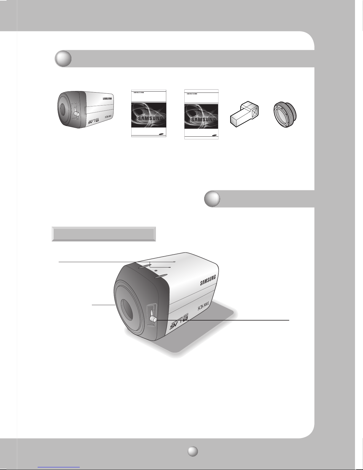
Components and Accessories
➊➋ ➍➎
➊
Supreme Resolution WDR Camera SCB-3000/3001
➌
Quick Set-up Guide
➎
C-Mount Adapter
Supreme Resolution
WDR Camera
User Manual
➌
Supreme Resolution
SCB-3000
SCB-3001
WDR Camera
Quick Set-up Guide
SCB-3000
SCB-3001
➋
Instruction Manual
➍
Auto Iris Lens Connector Plug
Overview
Front View
❶
➋
➊
Tripod Mounting Bracket Screw Hole
Used to fix the Tripod Mounting Bracket to the top of the camera.
➋
C-Mount Lens Adapter
Install this adapter to use a C-Mount Lens.
➌
Back Focus Control Lever
Adjust focus by this Back Focus Lever.
➌
COLOR CCD CAMERA User Guide
9
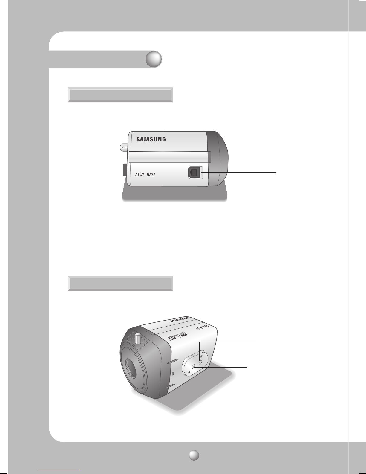
Overview
Side View
➍
Auto Iris Lens Connector
Used to connect Auto Iris Lens plug.
➍
Bottom View
COLOR CCD CAMERA User Guide
10
ö
Cannot fasten screws
here.
➎
ö
When fastening the
screw, make the
screw fastening part
head to the camera
module.
➎
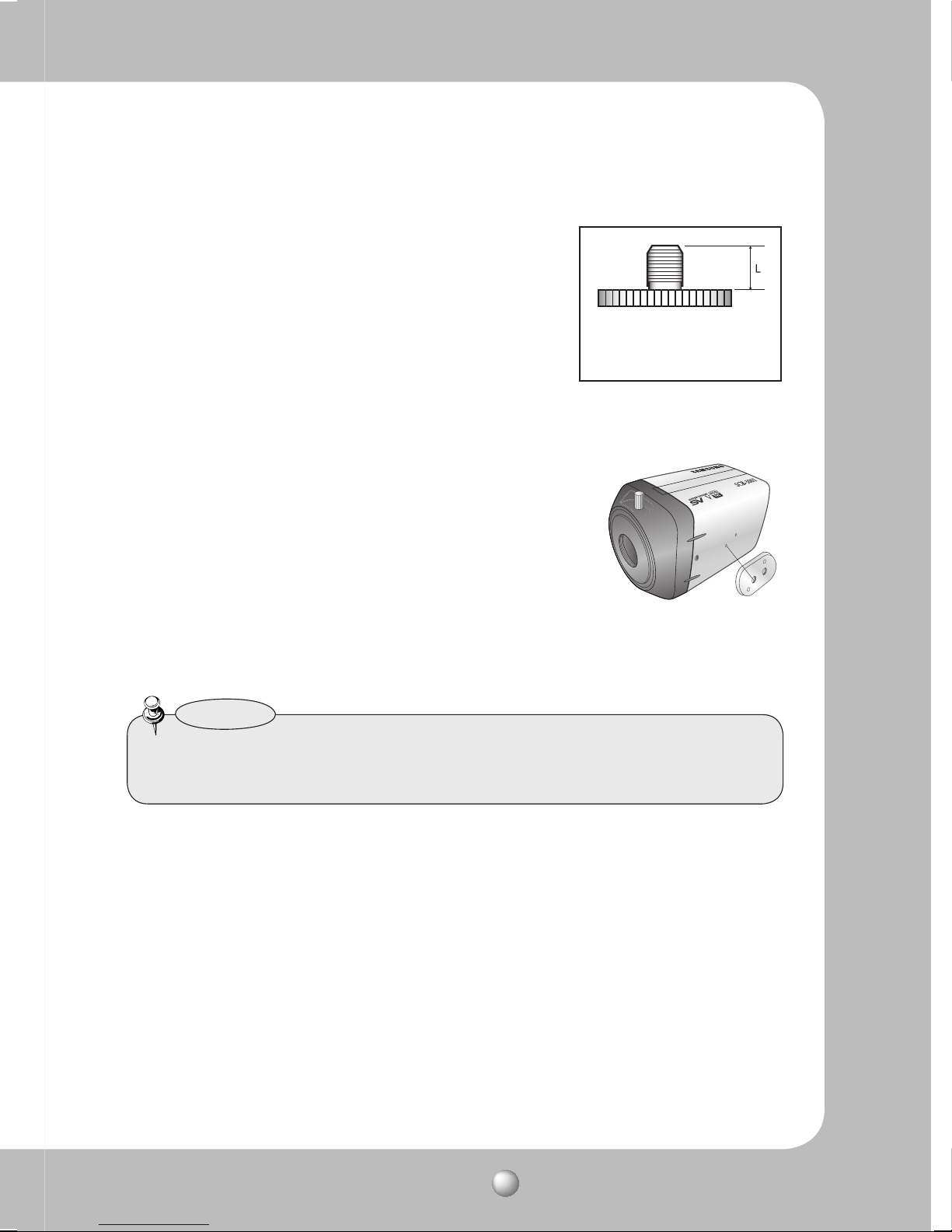
Tripod Mounting Bracket Screw Hole
Used to fix the camera on a bracket or tripod.
The screw sizes for this hole are as follows:
You can separate the Tripod Mounting Bracket and install it on the
*
top or bottom of the camera. Make sure to use the Tripod Mounting
Bracket when fixing the camera to a bracket or tripod. Otherwise
the camera may not be secure, or the internal circuitry of the
camera may be damaged.
1/4"-20 UNC (20 THREAD)
L:4.5mm±0.2mm (ISO standard),
or 0.197" (ASA standard)
Notes
• Tripod is not supplied with the camera. Please check the installed documentation of
tripod for the installation of cameras.
COLOR CCD CAMERA User Guide
11
Overview
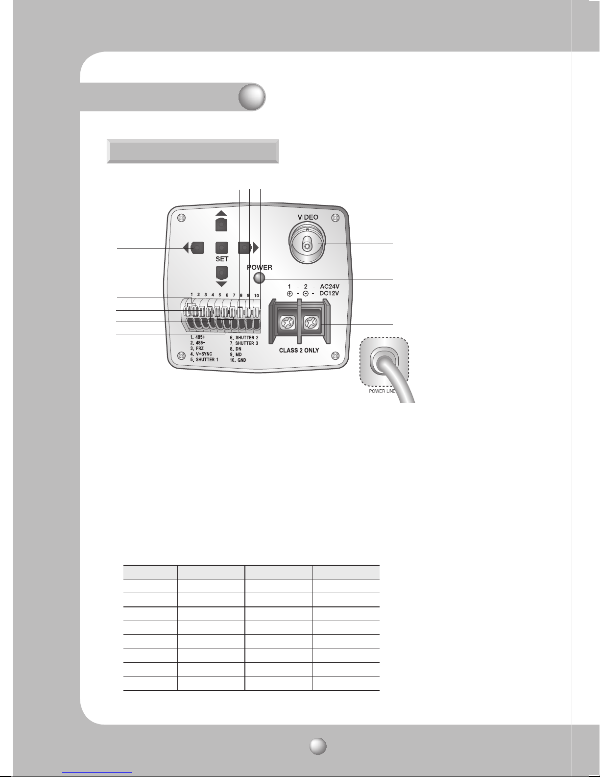
Rear View
⓫⓬⓭
➏
➐
➑
➒
❿
➏
Function Setup Button
⓮
⓯
⓰
*High Voltage Type
(SCB-3000/3001PH)
• SET button : Displays the menu on the screen and uses enter sub menu.
• Up
&
Down button : Used to move the cursor up or down in the menu screen.
• Left
&
Right button : Used to move the cursor left or right in the menu screen.
➐
RS-485 Control Port : You can control SETUP MENU through this port by using external
controllers like a Remote controller that RS-485 Communication is supported.
➑
FREEZE Mode Setting Terminal : Turns on or off FREEZE function.
➒
V-SYNC Input Terminal : Enables External Sync.
❿
Shutter Speed Select Terminal : Selects external sync shutter speed.
SHUTTER 1 SHUTTER 2 SHUTTER 3
1/60(1/50) OFF OFF OFF
1/120(1/100) ON OFF OFF
1/250 OFF ON OFF
1/500 ON ON OFF
1/700 OFF OFF ON
1/1000 ON OFF ON
1/1600 OFF ON ON
1/2500 ON ON ON
[Interlace mode]
COLOR CCD CAMERA User Guide
12

⓫
D & N Input Port : You can switch to Day & Night Mode by connecting an external signal to
this port.
⓬
MD Output Port : Motion detection signals are output through this port.
⓭
Ground Terminal
⓮
Video OUT Terminal :
Sends video signal and connects to the video input terminal of
the monitor.
⓯
Power LED : This lamp is lit when the camera is receiving power normally.
⓰
Power input terminal : Connects to the power appropriate to each model.
ö
External I / O port configuration
Num Name I/O Direction
1 RS-485+ I/O
2 RS-485- I/O
3 Freeze I
4 V-SYNC I
5-7 Shutter I
8DN I
9MD O
10 GND -
Notes
• When using the FREEZE Mode Setting Terminal, the Shutter Speed Select Terminal and
the D & N Input Port, Connect each of the terminals to the Ground Terminal.
COLOR CCD CAMERA User Guide
13
Installation
Lens
The lens is not supplied with this camera. Purchase a lens suitable for your
environment. This camera accepts the auto iris lens and both C-and CS-mount
lens.
Notes
• To use the functions of this camera effectively it is recommended that a DC type Auto Iris
lens is used.
• Keep the lens surface clean, if it becomes contaminated with dirt or fingerprints the
picture quality suffers.
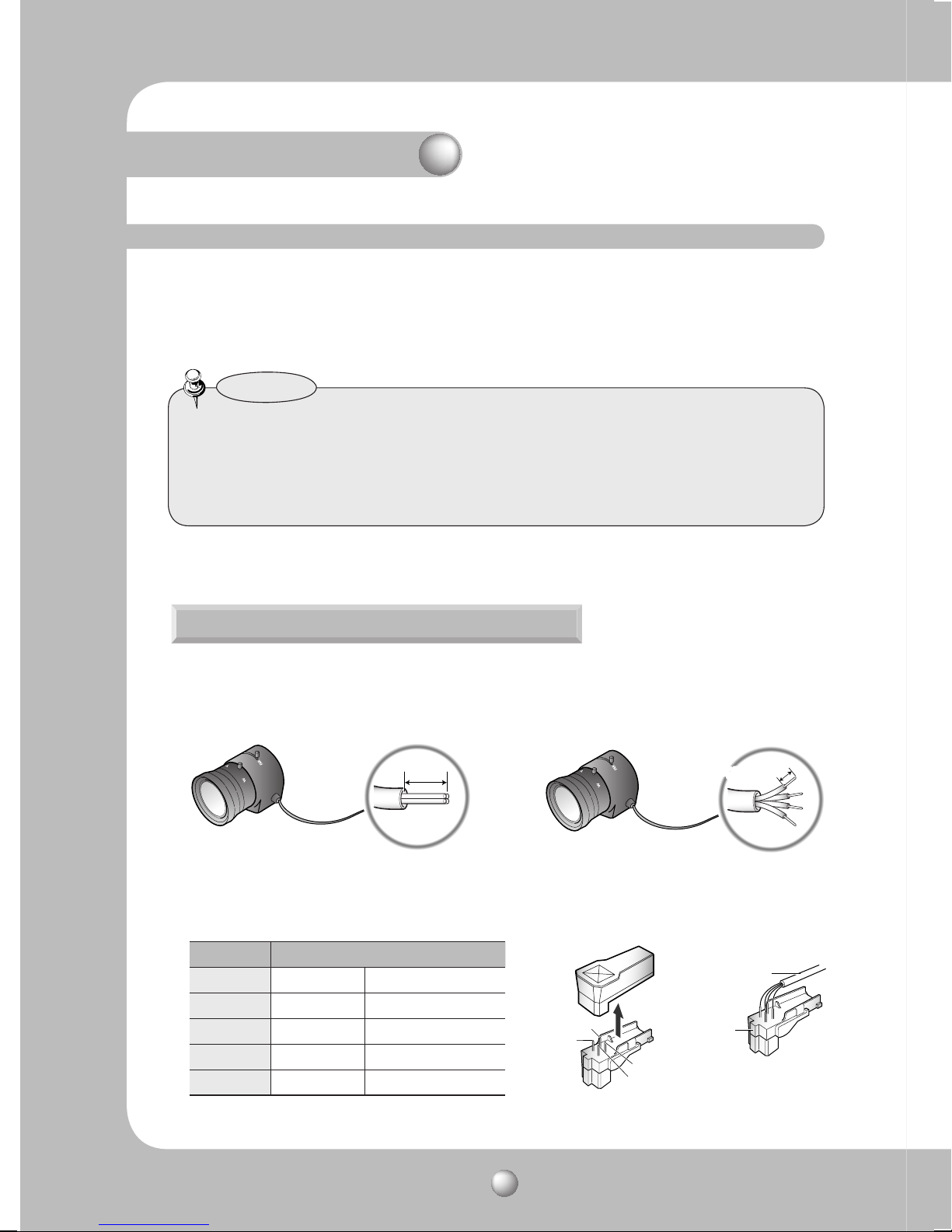
When Using Auto Iris Lens
1. Strip the insulation of the auto iris lens
cable 8mm from the end.
approx. 8mm
3. Remove the cover of the auto iris lens connector plug and solder the lens cable to
the connector pin of the plug.
LENS
Pin No. DC VIDEO
No.1 Pin Damping - Red (power)
No.2 Pin Damping + NC
No.3 Pin Drive + White (video signal)
No.4 Pin Drive - Black (GND)
2. Strip the insulation of the core of the
auto iris lens cable to expose a 2mm
length.
approx. 2mm
Lens cable
No. 3 Pin
No. 1 Pin
connector
No. 4 Pin
No. 2 Pin
COLOR CCD CAMERA User Guide
14
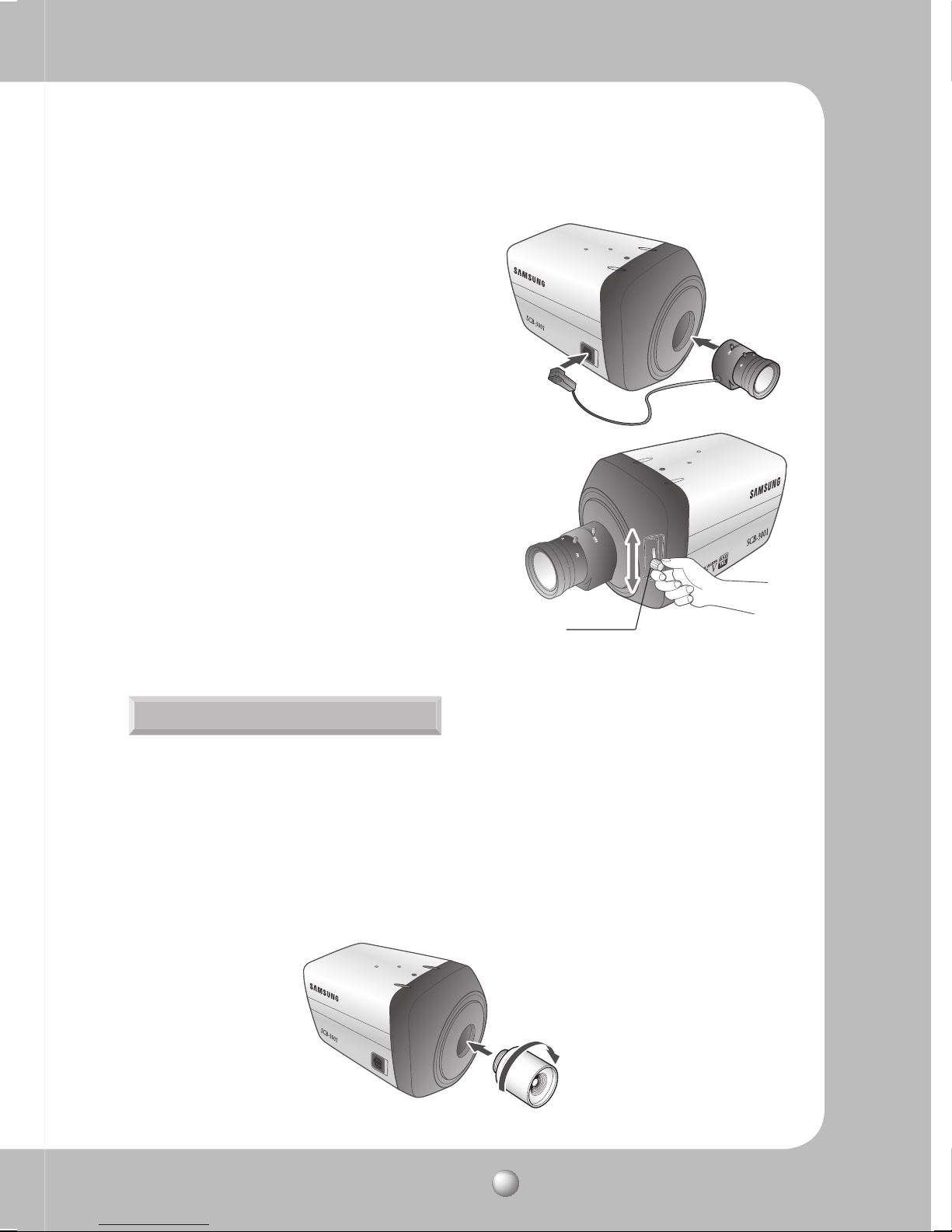
4. Fit the cover of the auto iris lens connector
plug, remove the protective glass cover
from the front of the camera, and fasten the
auto iris lens by turning it clockwise.
5. Set focus of camera using Back Focus Control
Lever of camera side after combining Auto
Iris lens.
Back Focus Control Lever
When Using a C/CS-Mount lens
Before installing a lens, identify whether the lens to be installed is a C-Mount or CS-Mount.
This camera is set for a CS-Mount Lens by default. To install a C-Mount Lens, a simple
modification is required.
• When Using a CS Mount Lens
Remove the protective glass cover at the front of this product and turn the CS-Mount Lens
clockwise to install it. And set focus of camera using Back Focus Control Lever of camera
side after combining CS-Mount lens.
COLOR CCD CAMERA User Guide
15
 Loading...