

Samsung SCB-2010 User Manual
P/No. : PT01-000128A
www.samsungtechwin.com
www.samsungsecurity.com
• SAMSUNG TECHWIN CO., LTD.
Samsungtechwin R&D Center, 701, Sampyeong-dong, Bundang-gu, Seongnam-si, Gyeonggi-do, Korea, 463-400
TEL : +82-70-7147-8740~60 FAX : +82-31-8018-3745
• SAMSUNG TECHWIN EUROPE LTD.
Samsung House, 1000 Hillswood Drive, Hillswood Business
Park Chertsey, Surrey, UNITED KINGDOM KT16 OPS
TEL : +44-1932-45-5300 FAX : +44-1932-45-5325
• SAMSUNG TECHWIN AMERICA Inc.
100 Challenger Rd. Suite 700 Ridgefield Park, NJ 07660
Toll Free : +1-877-213-1222 Direct : +1-201-325-6920
Fax : +1-201-373-0124
www.samsungcctvusa.com
SALES NETWORK
Accessories
High Resolution MINI Camera
User Manual
SCB-2010
User Guide
Quick Set-up Guide
M4 Taping
Screw 2EA
Installing Camera
1. Fix the camera to a ceiling using two screws.
2. After fixing it, adjust its pan base and tilt base
properly.
Screw
Hole
Installation
MINI CAMERA User Guide
7
MINI CAMERA User Guide
6
MINI CAMERA User Guide
5
MINI CAMERA User Guide
4
High Resolution Mini Camera
User Manual
SCB-2010
CAUTION
RISK OF ELECTRIC SHOCK.DO NOT OPEN
CAUTION: TO REDUCE THE RISK OF ELECTRIC SHOCK, DO NOT REMOVE COVER (OR
BACK) NO USER SERVICEABLE PARTS INSIDE. REFER SERVICING TO QUALIFIED
SERVICE PERSONNEL.
THIS SYMBOL INDICATES THAT DANGEROUS VOLTAGE CONSISTING A RISK OF
ELECTRIC SHOCK IS PRESENT WITHIN THIS UNIT.
THIS EXCLAMATION POINT SYMBOL IS INTENDED TO ALERT THE USER TO
THE PRESENCE OF IMPORTANT OPERATING AND MAINTENANCE (SERVICING)
INSTRUCTIONS IN THE LITERATURE ACCOMPANYING THE APPLIANCE.
WARNING
TO REDUCE THE RISK OF FIRE OR ELECTRIC SHOCK, DO NOT EXPOSE THIS APPLIANCE TO RAIN OR
MOISTURE.
TO PREVENT INJURY, THIS APPARATUS MUST BE SECURELY ATTACHED TO THE FLOOR/WALL IN
ACCORDANCE WITH THE INSTALLATION INSTRUCTIONS.
WARNING
BE SURE TO USE ONLY THE STANDARD ADAPTER THAT IS SPECIFIED IN THE SPECIFICATION SHEET.
USING ANY OTHER ADAPTER COULD CAUSE FIRE, ELECTRICAL SHOCK, OR DAMAGE TO THE PRODUCT.
INCORRECTLY CONNECTING THE POWER SUPPLY OR REPLACING BATTERY MAY CAUSE EXPLOSION, FIRE,
ELECTRIC SHOCK, OR DAMAGE TO THE PRODUCT.
DO NOT CONNECT MULTIPLE CAMERAS TO A SINGLE ADAPTER. EXCEEDING THE CAPACITY MAY CAUSE
ABNORMAL HEAT GENERATION OR FIRE.
SECURELY PLUG THE POWER CORD INTO THE POWER RECEPTACLE. INSECURE CONNECTION MAY CAUSE
FIRE.
WHEN INSTALLING THE CAMERA, FASTEN IT SECURELY AND FIRMLY. THE FALL OF CAMERA MAY CAUSE
PERSONAL INJURY.
DO NOT INSTALL THE UNIT IN HUMID, DUSTY, OR SOOTY LOCATIONS. DOING SO MAY CAUSE FIRE OR
ELECTRIC SHOCK.
IF ANY UNUSUAL SMELLS OR SMOKE COME FROM THE UNIT, STOP USING THE PRODUCT. IN SUCH CASE,
IMMEDIATELY DISCONNECT THE POWER SOURCE AND CONTACT THE SERVICE CENTER. CONTINUED USE IN
•
•
1.
2.
3.
4.
5.
6.
7.
SUCH A CONDITION MAY CAUSE FIRE OR ELECTRIC SHOCK.
IF THIS PRODUCT FAILS TO OPERATE NORMALLY, CONTACT THE NEAREST SERVICE CENTER. NEVER
DISASSEMBLE OR MODIFY THIS PRODUCT IN ANY WAY. (SAMSUNG IS NOT LIABLE FOR PROBLEMS CAUSED
BY UNAUTHORIZED MODIFICATIONS OR ATTEMPTED REPAIR.)
WHEN CLEANING, DO NOT SPRAY WATER DIRECTLY ONTO PARTS OF THE PRODUCT. DOING SO MAY CAUSE
FIRE OR ELECTRIC SHOCK.
CAUTION
DO NOT DROP OBJECTS ON THE PRODUCT OR APPLY STRONG BLOWS TO IT. KEEP AWAY FROM A LOCATION
SUBJECT TO EXCESSIVE VIBRATION OR MAGNETIC INTERFERENCE.
DO NOT INSTALL IN A LOCATION SUBJECT TO HIGH TEMPERATURE (OVER 50°), LOW TEMPERATURE (BELOW
-10°), OR HIGH HUMIDITY. DOING SO MAY CAUSE FIRE OR ELECTRIC SHOCK.
IF YOU WANT TO RELOCATE THE ALREADY INSTALLED PRODUCT, BE SURE TO TURN OFF THE POWER AND
THEN MOVE OR REINSTALL IT.
REMOVE THE POWER PLUG FROM THE OUTLET WHEN THERE IS A LIGHTING STORM. NEGLECTING TO DO SO
MAY CAUSE FIRE OR DAMAGE TO THE PRODUCT.
KEEP OUT OF DIRECT SUNLIGHT AND HEAT RADIATION SOURCES. IT MAY CAUSE FIRE.
INSTALL IT IN A PLACE WITH GOOD VENTILATION.
AVOID AIMING THE CAMERA DIRECTLY TOWARDS EXTREMELY BRIGHT OBJECTS SUCH AS SUN, AS THIS MAY
DAMAGE THE CCD IMAGE SENSOR.
APPARATUS SHALL NOT BE EXPOSED TO DRIPPING OR SPLASHING AND NO OBJECTS FILLED WITH LIQUIDS,
SUCH AS VASES, SHALL BE PLACED ON THE APPARATUS.
THE MAINS PLUG IS USED AS A DISCONNECT DEVICE AND SHALL STAY READILY OPERABLE AT ANY TIME.
DO NOT EXPOSE THE CAMERA TO RADIOACTIVITY. RADIOACTIVITY EXPOSURE MAY DAMAGE THE CCD.
FCC STATEMENT
THIS DEVICE COMPLIES WITH PART 15 OF THE FCC RULES. OPERATION IS SUBJECT TO THE FOLLOWING
TWO CONDITIONS :
1) THIS DEVICE MAY NOT CAUSE HARMFUL INTERFERENCE, AND
2)
THIS DEVICE MUST ACCEPT ANY INTERFERENCE RECEIVED INCLUDING INTERFERENCE THAT MAY CAUSE UNDESIRED
OPERATION.
8.
9.
1.
2.
3.
4.
5.
6.
7.
8.
9.
10.
MINI CAMERA User Guide
2
MINI CAMERA User Guide
3
Correct disposal of batteries in this product
(Applicable in the European Union and other European countries with separate battery return
systems.)
This marking on the battery, manual or packaging indicates that the batteries in this product
should not be disposed of with other household waste at the end of their working life. Where
marked, the chemical symbols Hg, Cd or Pb indicate that the battery contains mercury,
cadmium or lead above the reference levels in EC Directive 2006/66. If batteries are not
properly disposed of, these substances can cause harm to human health or the environment.
To protect natural resources and to promote material reuse, please separate batteries from
other types of waste and recycle them through your local, free battery return system.
Correct Disposal of This Product (Waste Electrical & Electronic Equipment)
(Applicable in the European Union and other European countries with separate collection systems)
This marking on the product, accessories or literature indicates that the product and its electronic
accessories (e.g. charger, headset, USB cable) should not be disposed of with other household waste
at the end of their working life. To prevent possible harm to the environment or human health from
uncontrolled waste disposal, please separate these items from other types of waste and recycle them
responsibly to promote the sustainable reuse of material resources.
Household users should contact either the retailer where they purchased this product, or their local
government office, for details of where and how they can take these items for environmentally safe
recycling.
Business users should contact their supplier and check the terms and conditions of the purchase contract.
This product and its electronic accessories should not be mixed with other commercial wastes for disposal.
Caution
THIS EQUIPMENT HAS BEEN TESTED AND FOUND TO COMPLY WITH THE LIMITS FOR A CLASS A
DIGITAL DEVICE, PURSUANT TO PART 15 OF FCC RULES. THESE LIMITS ARE DESIGNED TO PROVIDE
REASONABLE PROTECTION AGAINST HARMFUL INTERFERENCE WHEN THE EQUIPMENT IS OPERATED
IN A COMMERCIAL ENVIRONMENT.
THIS EQUIPMENT GENERATES, USES, AND CAN RADIATE RADIO FREQUENCY ENERGY AND, IF NOT
INSTALLED AND USED IN ACCORDANCE WITH THE INSTRUCTION MANUAL, MAY CAUSE HARMFUL
INTERFERENCE TO RADIO COMMUNICATIONS. OPERATION OF THIS EQUIPMENT IN A RESIDENTIAL
AREA IS LIKELY TO CAUSE HARMFUL INTERFERENCE IN WHICH CASE THE USER WILL BE REQUIRED
TO CORRECT THE INTERFERENCE AT HIS OWN EXPENSE.
IC COMPLIANCE NOTICE
THIS CLASS A DIGITAL APPARATUS MEETS ALL REQUIREMENTS OF THE CANADIAN
INTERFERENCE.-CAUSING EQUIPMENT REGULATIONS OF ICES-003.
Read these instructions.
Keep these instructions.
Heed all warnings.
Follow all instructions.
Do not use this apparatus near water.
Clean only with dry cloth.
Do not block any ventilation openings. Install in accordance with the manufacturer’s instructions.
Do not install near any heat sources such as radiators, heat registers, or other apparatus (including amplifi ers) that produce heat.
Do not defeat the safety purpose of the polarized or grounding-type plug. A polarized plug has two blades with one wider than
the other. A grounding type plug has two blades and a third grounding prong. The wide blade or the third prong is provided for
your safety. If the provided plug does not fi t into your outlet, consult an electrician for replacement of the obsolete outlet.
Protect the power cord from being walked on or pinched particularly at plugs, convenience receptacles, and the point where
they exit from the apparatus.
Only use attachments/accessories specifi ed by the manufacturer.
Use only with cart, stand, tripod, bracket, or table specifi ed by the manufacturer, or sold with the apparatus.
Unplug this apparatus when a card is used. Use caution when moving the cart/ apparatus combination to
avoid injury from tip-over.
Refer all servicing to qualifi ed service personnel. Servicing is required when the apparatus has been damaged
in any way, such as powersupply cord or plug is damaged, liquid has been spilled or objects have fallen into
the apparatu
s, the apparatus has been exposed to rain or moisture, does not operate normally, or has been dropped.
1.
2.
3.
4.
5.
6.
7.
8.
9.
10.
11.
12.
13.
14.
High Resolution
By adopting a diagonal 6mm(1/3") 410,000(NTSC) pixel, 470,000(PAL) pixel SONY CCD, the camera produces clear
picture quality with a horizontal resolution of 600 TV lines for color.
Excellent Sensitivity
The built-in high sensitivity COLOR CCD produces a clear image even in 0.04 Lux or lower illumination.
Features
Important Safety Instructions
SSNR3 Function (Samsung Super Noise Reduction)
The high-performance W-V DSP chip effectively removes low-light gain noise and afterimage to provide clear images
even in dark environments.
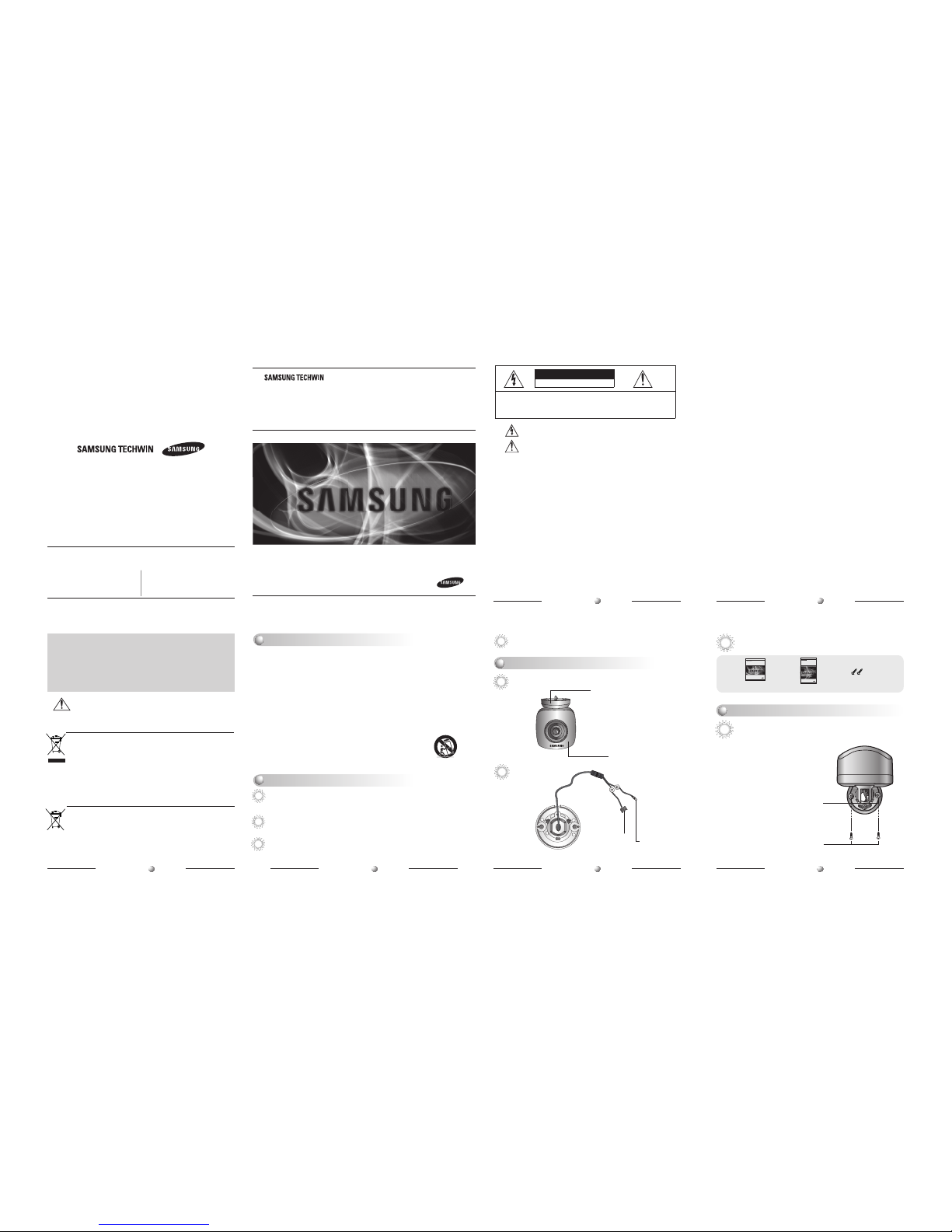
Pan and Tilt
Pan and tilt are available after installing camera.
Tilt Base
You can adjust up and down
the camera(0º~175º)
BNC Jack
Power Input
Terminal
Pan Base
You can rotate the lens(0º~60º)
Getting to Know Your Camera
Front
Bottom
High Resolution Mini Camera
Quick Set-up Guide
SCB-2010
MINI CAMERA User Guide
12
MINI CAMERA User Guide
13
MINI CAMERA User Guide
14
MINI CAMERA User Guide
15
MINI CAMERA User Guide
11
MINI CAMERA User Guide
10
MINI CAMERA User Guide
9
MINI CAMERA User Guide
8
• When installing the camera on a ceiling, note that not to damage or squeeze the cables.
Notes
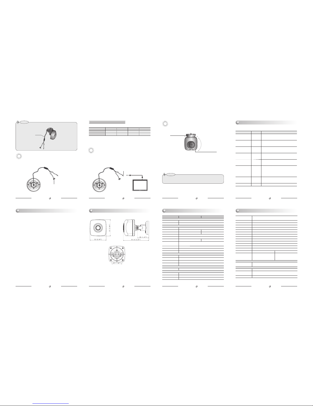
Connecting to Power
•
Connect the adapter to the power input connector as shown in the figure below.
Use a DC 12V. (The Adapter is not provided with the Camera.)
MINI Camera
Power Input Connector
MINI Camera
Connection to Monitor
•
As a connecting method varies according to instruments, refer to the manual supplied
with the instrument.
• Connect the cable after power is turned off.
Resistance of copper wire [at 20Cº(68ºF)]
• As the voltage drop according to the length of the cable in the above table,
a camera may malfunction if there is an excessively long cable run.
* Voltage for camera operation: 12V DC ±10%
* Voltage drops in the above table are variable according to types of cable manufacturer.
For DC Power Type
Connect the VIDEO-OUT jack to the VIDEO-IN jack of monitor.
• In case of adjusting the tilting, do not take the lens for preventing hysical shocks. Please take the Tilt Base.
• This camera is to be installed on the ceiling by factory default.
Notes
Panning & Tilting Control
You can adjust the Panning and Tilting angle freely. (Panning angle: 0º-60º, Tilting
angle: 0º~175º)
1)
Adjustment Panning angle: After attaching the camera to a ceiling, adjust the panning
angle for better monitoring area by rotating the Pan Base. The panning angle can be
adjusted by 0º~60º.
2) Adjustment Tilting angle: After attaching the camera to a ceiling, adjust the tilting
angle for better monitoring area by rotating the Tilt Base. The tilting angle can be
adjusted from 0º to 175º freely. (based the ceiling surface)
Pan Base
You can rotate the lens by
0º~60º
Tilt Base
You can adjust up and down
the camera (0º~175º).
If you have trouble operating your camera, refer to the following.
If the guidelines do not enable you to solve the problem, contact an authorized
technician.
◾ The image on the screen is dim.
• Check if the lens are stained. If dirty, clean the lens with soft, clean cloth.
•
The image is dimmer at night than daytime. If the focus is not right, adjust it at daytime.
◾ The contrast on the screen is too weak.
• Adjust the contrast feature of the monitor.
• If the camera is exposed under too strong light, change the camera position.
• Adjust the lens BACK FOCUS again.
◾ The camera is not work properly, and the surface of the camera case is hot.
• Check that you have connected the camera to a proper power (DC 12V).
Monitor
BNC
Built-in functions of the SCB-2010 Camera include the following
✽ If you need to control OSD menu, It needs coaxial controller.
Camera Operation
Troubleshooting
Dimension
SpecificationSpecification
Copper wire size (AWG)
#24(0.22mm2) #22(0.33mm2) #20(0.52mm2) #18(0.83mm2)
Resistance ( Ω / m)
0.078 0.050 0.030 0.018
Voltage Drop (V/m) 0.028 0.018 0.011 0.006
Auto Functions Setting Descriptions
Electronic Shutter
Speed
ESC
The shutter is controlled according to the
brightness of screen by automatically.
WHITE BALANCE ATW
It can be used within the color temperature
range 1,700K ~ 11,000K.
BACKLIGHT OFF
It helps view a desired area of picture at the
backlight condition.
GAIN CONTROL HIGH
The gain increases or decreases within the
range of 6dB~34dB.
SSNR3
(Noise Reduction)
ON
There is sufficient reduction in noise levels
without causing much ghost imaging.
SENS-UP AUTO
It helps maintain a bright, clear screen image by
automatically detecting changes in the level in
low light levels without causing much ghost
imaging.
SHARPNESS ON
The outline of the video image becomes cleaner
and more distinctive.
LENS SHADE ON It helps correct shading of Lens.
SCB-2010N SCB-2010P
ELECTRICAL
Input Voltage DC 12V ±10%
Power Consumption Max 1.8W
VIDEO
Imaging Device 1/3 inch, Sony Super HAD CCD II
Total Pixels 811(H) x 508(V) 795(H) x 596(V)
Effective Pixels 768(H) x 494(V) 752(H) x 582(V)
Scanning System 2:1 Interlace
Synchronization Only Internal
Frequency H : 15.734KHz V : 59.94Hz H: 15.625KHz V : 50.00Hz
Horizontal
Resolution
color: 600TVL
Min. Illumination color: 0.04 Lux (50 IRE@F1.2, Sens-up 2x)
S / N (Y signal) 52dB (Weight On, AGC Off)
Video Output CVBS : 1.0Vp-p, 75Ω composite
LENS
Focal Length 3mm
Angular Field of View
H : 95°, V : 71°
Max. Aperture Ratio
F2.0
Min. Object Distance
0.4m
PAN / TILT
Pan / Tilt Range 0° ~ 60° / 0° ~ 175°
OPERATIONAL
Shutter Mode ESC, A.FLK, Manual
Lens Shade On / Off (Level adjustable)
SSDR On / Off (Level adjustable)
※
The specification for this product may change without prior notice for product improvement.
Backlight
Compensation
USER BLC / HLC / OFF
Day & Night COLOR / BW / AUTO (Electric Type)
Gain Control Low / High / Off
White Balance ATW / Outdoor / Indoor / Manual / AWC (1,700°K ~ 11,000°K)
SENS-UP Auto / Off (Selectable x2 ~ x512)
Motion Detection On / Off (8 Programmable zones)
Privacy Masking On / Off (12 Programmable zones)
SSNR3 On / Off (Level adjustable)
Digital Zoom On / Off (x1 ~ x16)
DIS On / Off
Camera Title On / Off (Displayed 15 Characters)
Sharpness On / Off (Level adjustable)
Flip / Mirror On / Off
Communication Coaxial (Pelco Coaxitron)
Electronic Shutter Speed
1/60 ~ 1/120,000 sec 1/50 ~ 1/120,000 sec
On Screen Display
English, Korean, Japanese, Spanish,
French, Portuguese, Taiwanese
English, Chinese, German, Italian,
French, Spanish, Russian, Czech, Polish,
Romanian, Serbian, Swedish, Danish,
Turkish, Portuguese
ENVIRONMENTAL
Operating Temperature /
Humidity
-10°C ~ +50°C (+14°F ~ +122°F) / Less than 90% RH
MECHANICAL
Color/Material Ivory/Plastic
Dimension(W x H x D)
52 x 52 x 40.4mm(without bracket)
52 x 52 x 81.4mm(with bracket)
Weight
95g (with bracket)
BNC-Power Cable
UNIT: mm(inch)
0°~175°
0°~60°
---- Power Input
Terminal
 Loading...