

Samsung SBB-SNOWJ3U, SBB-SNOWJMU, LH025IFH-DS, LH040IFH-DS, LH060IFH-DS Installation Manual
...
LED Display
Installation Manual
Ver. 2.9
LH025IFH*DS (P2.5)
LH040IFH*DS (P4.0)
Samsung Electronics
LH060IFH*DS (P6.0)
LH085IFHLDS (P8.5)
SBB-SNOWJ3U
SBB-SNOWJMU
Revision History
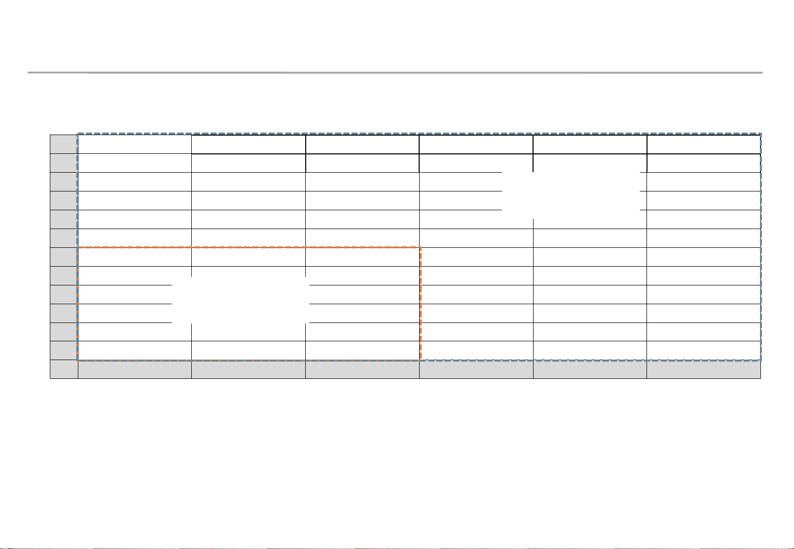
Version Date (Y/M/D) Description
2.0 2020/03/20 New Release
2.1 2020/06/19 Add SNOW1810U installation and Picture Setting
2.2 2020/08/07 Add Test Pattern function
2.3 2020/11/02 Modify dehumidification guide
2.4 2020/11/16 Add Network IP Setting by USB
2.5 2020/11/27 Update LSM guide
2.6 2020/12/01 Update Dehumidification Guide
2.7 2020/12/01 Update Picture Option
2.8 2020/12/14 Update Ventilation Guide
Samsung Electronics
2.9 2020/12/29 AC placement guide to prevent condensation
1

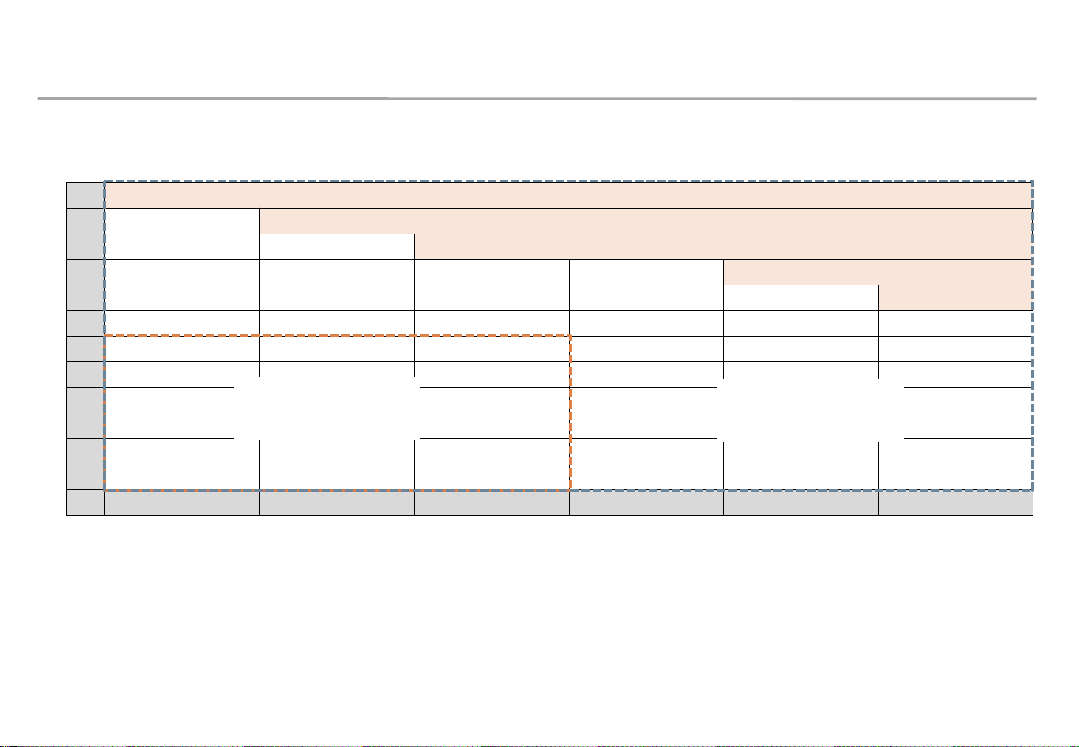
Table of Contents
1. Product Information and Precautions for Installation
2. Check Point about the Radiant Heat
3. Preparation for Product Installation
4. Frame Installation
5. LED Display Installation
6. S-BOX Connection
Samsung Electronics
7. Settings and How to Use
8. Issue and Solution
9. Cable Connection
10. Seam Adjustment
2
This contents must be noticed to customer.
Please print this page and hand it to user.
Dehumidification guidance – during installation
Samsung Electronics
When moist gets into LED package because of high humidity, ‘Line defect’ can
be caused by electrical short inside of LED Package.
For keeping the best quality of products during installation, please refer to the
below cautions.
- If the condition meets one of the below cases at least, dehumidification MUST be
processed. Do not play any contents on the screen before dehumidification finishes.
∙ Case when vacuum packaging is already unsealed before unpacking products.
∙ Case when environment condition is worse than Samsung working condition (0°C~40°C/10~80%RH).
∙ Case when it elapses longer than 7 days after unpacking them, even though the environment condition
satisfies Samsung working condition (0°C~40°C/10~80%RH).
∙ Case when production date on the label elapses more than 6 months, even though vacuum packaging is
sealed.
∙ Case when volatile chemicals such as oil paint, solvent are used in same place of installation.
(You can refer to Product Information and Precautions for Installation part in detail.)
- If the screen needs dehumidification on installation, MUST follow the directions of next page.
This contents must be noticed to customer.
Please print this page and hand it to user.
Dehumidification guidance – during installation
Samsung Electronics
How to install the screen in the case that dehumidification is necessary
※ Before finishing the directions explained in next pages, never play other contents or use them.
※ If the installation site has higher humidity, it is highly recommended to use dehumidifier.
(If A/C turned off after working hour, it may make humidity higher and cause line defects.)
※ Chilled air from A/C should never touch LED surface directly.
※ If thermo-hygrometer is equipped on the site while the screen is installed, it is useful to analyze
the cause of line defects.
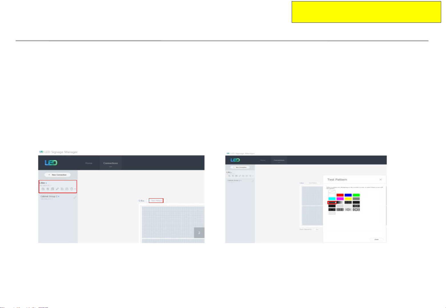
1. Play a specific pattern of LSM program without any cabinets.
(This pattern should be used. If other pattern is used, it can cause line defects.)
① Select S-Box and Test Pattern
② Set darker gray pattern among various patterns.
2. Inspect cabinets with darker solid patterns(W/R/G/B) and turn off cabinets.
(It should take less than 30 seconds to show each solid patter and you can refer to
Screen check’ category in detail.)
‘Process of
This contents must be noticed to customer.
Please print this page and hand it to user.
Dehumidification guidance – during installation
How to install the screen in the case that dehumidification is necessary.
3. While installing cabinets, S-Box should play only this pattern.
• Check S-Box shows the pattern through monitor connected to S-Box service port.
• After installing each cabinet, check whether the pattern is shown in it.
• OCM cable connection can be checked through this.
• Before turning off S-Box, turn off the cabinets, first.
• After being sure S-Box plays this pattern, turn on the cabinets.
Samsung Electronics
4. After completing installation of cabinets, start 24hr dehumidification process.
5. After finishing 24hr dehumidification process, do edge correction and module calibration.

This information should be noticed to customer.
Please print this page and hand it to user.
Dehumidification guidance – during operation
Samsung Electronics
• Electrical short in package is possible to happen during products are working.
• For keeping quality of products during installation, please refer below cautions.
– If one of below case meet during operation, MUST do dehumidification process.
Case when environment condition is exceed operation condition.
Case when products are not working more than 1 month, even though environment condition is under
operation condition.
– When environment condition is exceed operation condition, products are out of warranty.
Please check environment condition.
– Even products are operating, if the installed place have extra construction such as interior
modification, MUST do dehumidification following installation condition.
– It is possible to happen dew condensation on surface of products, even though working on
operating condition. When happening dew condensation, MUST operate after cleaning the dew
condensation & dehumidification.
This information should be noticed to customer.
Please print this page and hand it to user.
Dew condensation due to overcooling
Samsung Electronics
Even though meet with Samsung recommended operation
condition, dew condensation is possible to happen when
surface of products is colder than environment temperature or
hot & humid air blow to cooled surface of products.
(cf : Principle of happening dew on surface of glass which have ice)
Case when dew condensation is happen on products, it is
possible to be the root of defect. In this case, it is possible to
be out of warranty.
This information should be noticed to customer.
Please print this page and hand it to user.
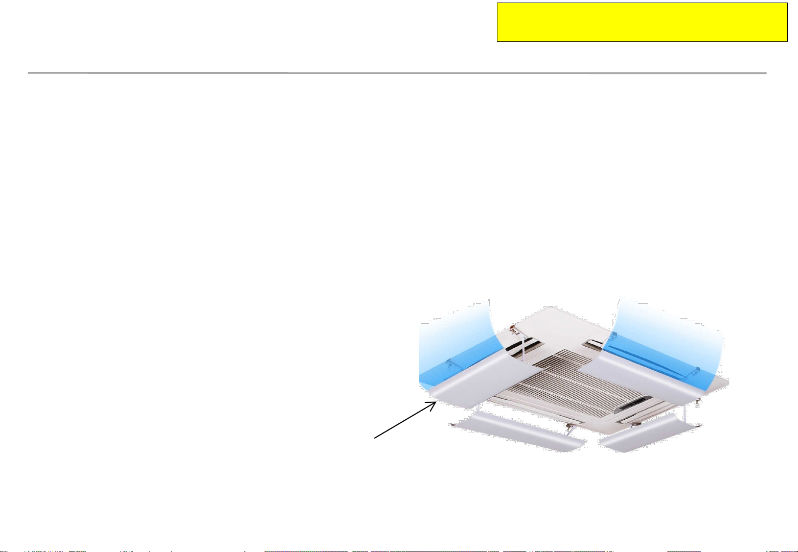
Prevent condensation due to A/C
Samsung Electronics
Make sure that the cold air does not blow directly on the screen.
– When the cold air from A/C (air conditioner) blows directly onto the screen surface,
condensation may occur depending on the ambient humidity and temperature of
screen surface.
– If the A/C and screen are close, install a wind deflector as shown in the figure
below to prevent condensation.
Install the wind deflector toward the screen.

Guidance of latest firmware
When install products, please update latest firmware on online
- You can download latest firmware from SLM site.
∙ URL of SLM Page : https://www.secslm.com
∙ After login Help Download Center에서 Download
∙ Before you download firmware, you MUST check same firmware of model (marked red
letter in below) & upper number of version (marked blue in below).
Cabinet : Main - L-xxxMWWAC-nnnn.n xxx = Pan name, nnnn.n = version
FPGA - aabbd_ddddd aa = pixel pitch, bb = LED package type, d_ddddd= version
Example : IER P2.5 Cabinet : L-IERMWWAC-1003.1, FPGA : 25252-31046
Samsung Electronics
S-box : TB-KTM2SBMDWWC_100x.x
- You can update firmware through LSM.
∙ Please refer ‘7-1 PC control program’ for the way to update firmware.
9
1. Product Information and Precautions for Installation
• Power cable and OCM cable must be inserted tightly.
• Use *STP, *FTP Cable over CAT6, which length is about 15 ~ 100m for HDBT signal stability.
“Do not use CAT6 UTP”
Do not break or bind the cable into bundle.
• Do not mix the cabinets that have different project number each other.
Each cabinet has its own project number.
Samsung Electronics
10
1. Product Information and Precautions for Installation
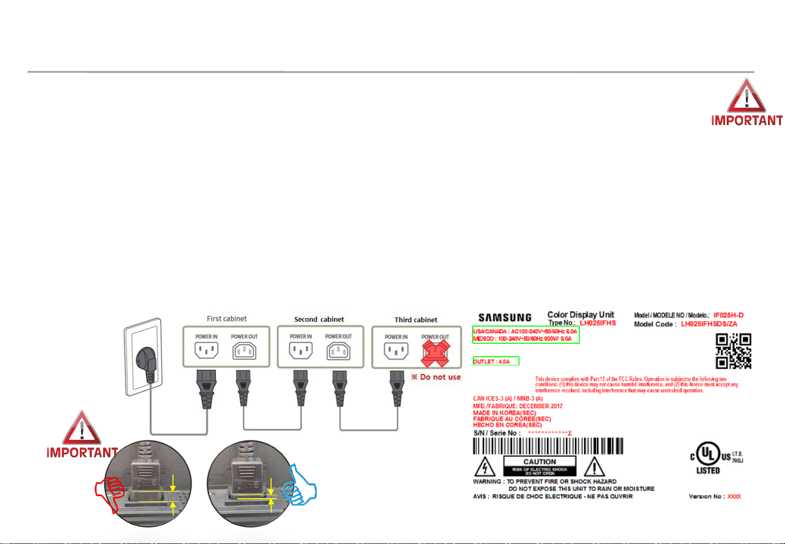
• If using 110V/220V, you can connect at most 3 IFH-D(IF040/IF060/IF025) devices.
• Exceeding the recommended maximum number of devices can cause the circuit breaker of the
product to trigger due to overload. SURELY CONNECT the devices less than the recommended
maximum number of devices.
※ No responsible for Samsung Electronics in case of exceeding the recommended maximum
number of devices connection.
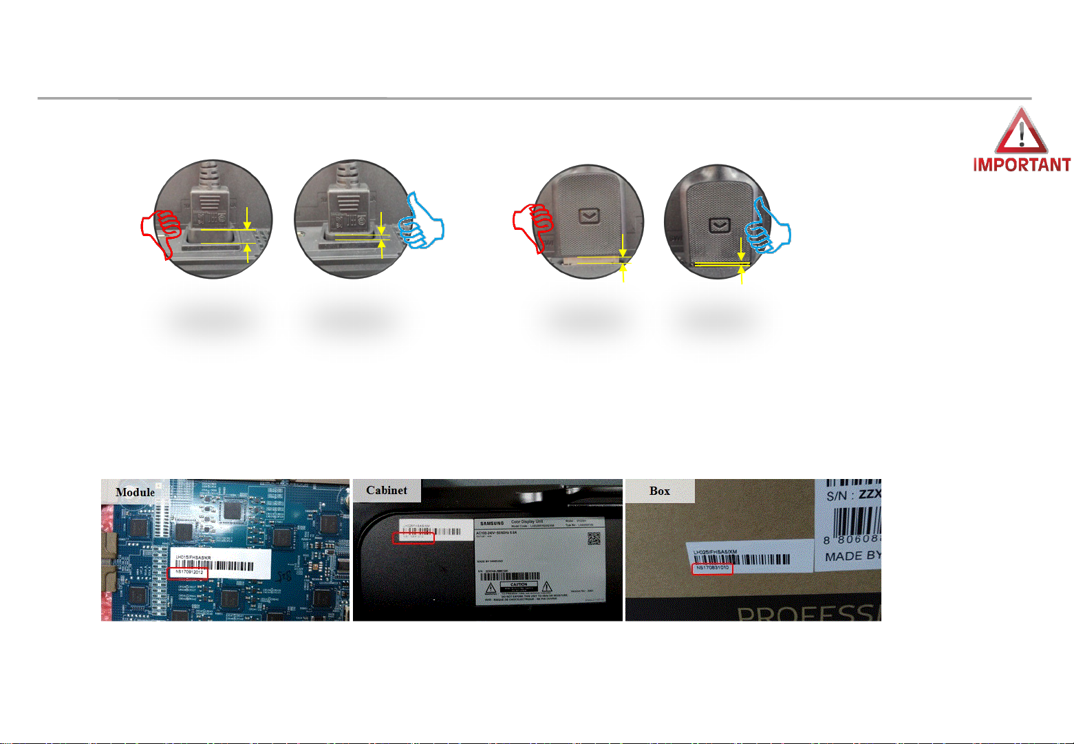
• The label info which is attached behind product shows rated power of cabinet and rated current of
outlet.
Samsung Electronics
11
1. Product Information and Precautions for Installation
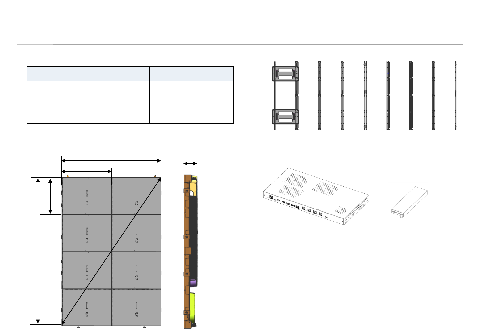
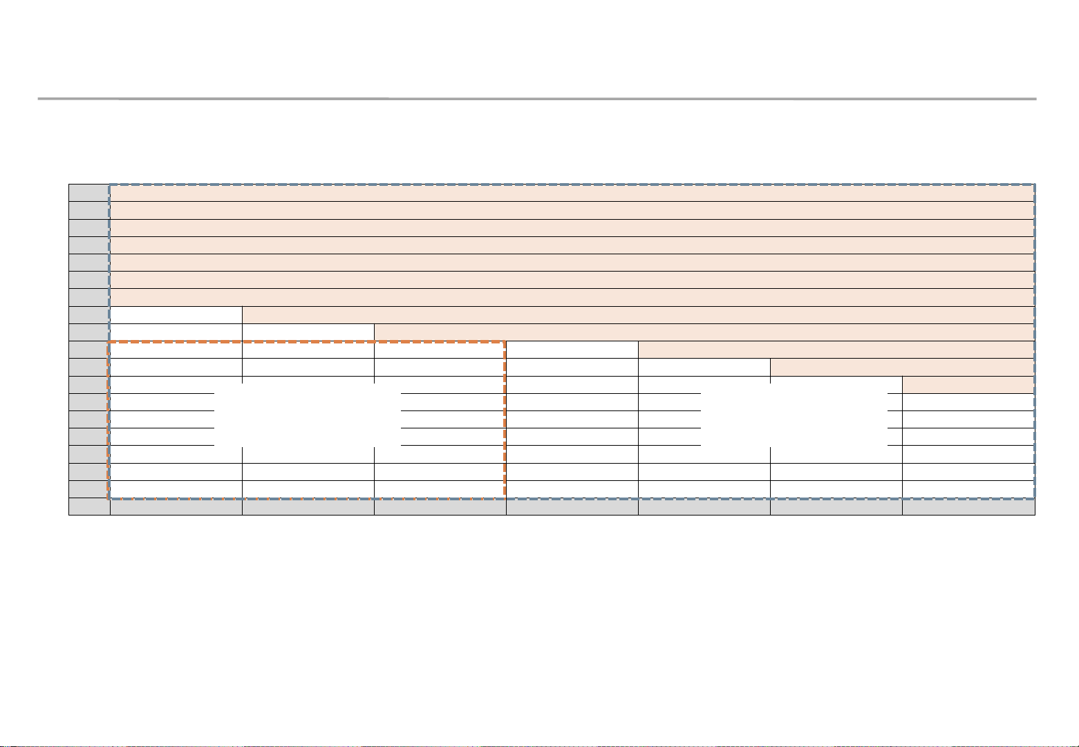
◇ Frame Kit Composition ( Refer to Page 29 )
Frame Kit Composition Size [mm]
Samsung Electronics
VG-LFH81SWD
VG-LFH82SWD
VG-LFH83SWD
8x1(8 Set)
8x2(16 Set)
8x3(24 Set)
3840 x 720 (1 row)
3840 x 1440 (2 rows)
3840 x 2160 (3 rows)
◇ Cabinet Product Information ( Fig2.)
479.9
239.9
179.9
34”
719.9
64.2
<8x2 Frame>
◇ SBB-SNOWJ3U (S-Box, I/G)
<S-Box> <I/G>
(Interface Gender)
※ Power system should be designed
according to Screen composition. 1 FHD
Screen should be in same power system.
(Refer to page 69 )
12
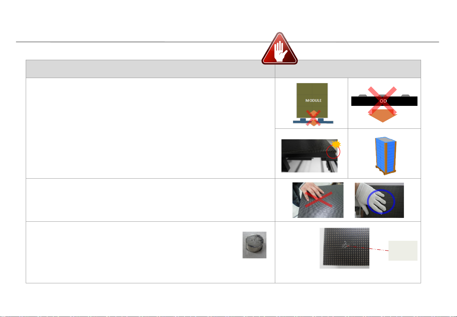
1. Product Information and Precautions for Installation
◇ Precautions for Installation (LED Physical damage)
Precautions Images
[ Beware of Outside Impact, Fall]
Samsung Electronics
① Beware not to cause any impact on the LED screen or drop the product on the floor
after the protection gets taken off for installation.
② Beware not to put the LED side headed downwards to the floor after the protection
gets taken off for installation.
③ Beware not to have the corner area of LED module be damaged due to the contact
with the outside.
④ Beware not to put more than 12 layers.
[Beware of LED Damage due to Static Electricity]
▶ Beware not to touch LED screen with bare hands without putting gloves on.
[Beware of LED Damage due to Metallic Substances]
▶ Beware not to have metallic substances pulled in to the surface
due to the magnetic force on the front side of the LED.
▶ If any metallic substances get drawn in on the surface, please disassemble the
MODULE
Front
① ②
③ ④
Metallic
substance
module and then remove the pollutants by using a magnet.
13
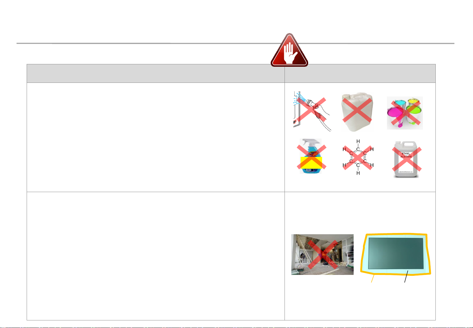
1. Product Information and Precautions for Installation
◇ Precautions for Installation (LED Chemical damage)
Precautions Images
[Beware of LED Damage due to chemicals]
▶ Beware not to contact the following materials with the product, and minimize
exposure of the product to their vapor
- Water (including sweat and saliva)
- Detergents (e.g. detergents for carpet cleaning)
- Paint, glass cleaner, mosquito repellent, fragrance
- Substances containing benzene, toluene, xylene, solvent, surfactant,
thinner, chlorine, etc.
▶ When the product is installed, the air conditioner should be operated enough to
minimize sweat flow, and avoid sweating the product.
▶ Minimize saliva by wearing a mask
[Precautions for construction and cleaning]
▶ When installing on the construction site, it should be installed after construction and
cleaning.
▶ If there is construction inevitably in the space where the product is installed, take
the following measures.
- To minimize the exposure of the product to dust and solvent vapors,
the whole product is covered with a vinyl shield,
and tape is used to attach the end of the vinyl shield to the wall.
- Operate video or 100 gray scale white for more than 2 hours every day.
- After the construction is finished, remove the vinyl shield after the dust and
solvent vapor have been sufficiently removed.
▶ When cleaning the floor with detergent or water, install a shield when there is a
possibility of reaching the product.
GLASS
CLEANER
CARPET
CLEANER
Samsung Electronics
Tape Vinyl shield
14

1. Product Information and Precautions for Installation
◇ Preparations for Installation
10.0mm Wrench
Electric Driver
(-) (+) Driver
Samsung Electronics
LED MODULE JIG
(model name: CY-LJFNAS)
Service JIG
(BH81-00001A)
Holder Magnet Tool
Plier
Antistatic
Glove
15
2. Check Point about the Radiant Heat
Samsung Electronics
◇ Radiate heat guide
INDOOR Installation Condition
- SAMSUNG WALL MOUNT Using Condition(ADA Satisfied)
∙ Product Front to Wall Gap : 90mm
∙ Product Rear to Wall Gap : 25mm
- When sunlight light up
∙ Need inquiry when sunlight shine through window or wall
- Air conditioner effect
∙ Avoid cold&hot air
※ Written under ‘Full white, (back light 7)’ standard
Written under ‘Video, (back light 10)’ standard
※ ADA (American’s with Disabilities Act)
90mm
Outdoor temp
check position
wall
- Outdoor temperature measure spot
∙ Center of Product & Air inlet
Outdoor temp
check position
25mm
16
2. Check Point about the Radiant Heat– without Fan
Minimum spacing for wall mounting installation
Min condition : 30mm (set ~ ceiling)
Recommended condition : more than 500mm
Air vent area
Air vent area
WALL
(more than 60%
of opening rate)
Samsung Electronics
Min condition: 30mm (set ~ floor)
Recommended condition : more than 500mm
Air vent area
(more than 60%
of opening rate)
17
2. Check Point about the Radiant Heat– without Fan
Minimum spacing for processed installation
Min condition : 0mm (set ~ ceiling)
Recommended condition : more than 500mm
Samsung Electronics
Essential cond. : more than 30mm of 100% opening rate
WALL
Essential cond. : more than 30mm of 100% opening rate
Min condition: 0mm (set ~ floor)
Recommended condition : more than 500mm
Air vent area
Air vent area
18
2. Check Point about the Radiant Heat
◇ Axial FAN(selection example)
Samsung Electronics
6
5 80 CFM
4 65 CFM
3
2
1
※ Example) Total CFM? (Outdoor temperature 30℃ , Cabinet (5x5) on condition.)
※ FAN flow rate is not a MAX, but a real flow rate.
No need for FAN
1 2 3 4 5 6 7 8 9 10 11 12
→ 80CFM x 5 = 400CFM
- Ebm papst : http://www.ebmpapst.com
∙ Model name : 614 J/2 HHP Size : 60*60*32
∙ Flow rate : MAX 48.3 CFM FAN : 3ea per column
∙ delta-fan : http://www.delta-fan.com
∙ Model Name : AFB0612HHE Size : 60*60*38
※ Fan Margin for the pressure drop / flow reduction
95 CFM
FHD
UHD
No need for FAN
Total 400 CFM
80CFM 80CFM 80CFM 80CFM80CFM
FAN
Outdoor
temperature
30℃
5 Cabinets
∙ Flow rate : MAX 54.5 CFM FAN : 3ea per column
※ Fan Margin for the pressure drop / flow reduction
5 Cabinets
19
2. Check Point about the Radiant Heat
Samsung Electronics
◇ FAN Using condition
- Air Vent : install at bottom
- Top: Seal except fan hole
FAN
WALL
Seal right and left side
좌우측면 밀폐
FAN
Seal except fan hole
◇ Vent specification
Using over 70% open ratio vent
- Open ratio (%) =
B
d
. ℎ
Air vent area
(Bottom only)
c
A
20
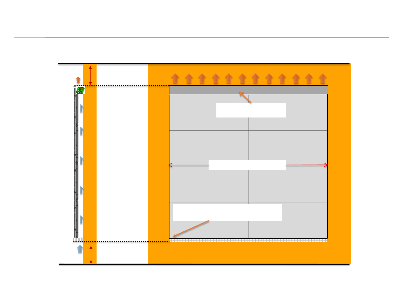
2. Check Point about the Radiant Heat– with Fan
Example of minimum spacing and FAN allocation for wall mounting installation
Min condition : 30mm (set ~ ceiling)
Recommended condition : more than 500mm
Other parts except for FAN
area should be sealed
left and right should be sealed
WALL
left and right sealing
Samsung Electronics
Air vent area should be mesh type with
an opening rate of more than 60%.
Min condition: 30mm (set ~ floor)
Recommended condition : more than 500mm
21
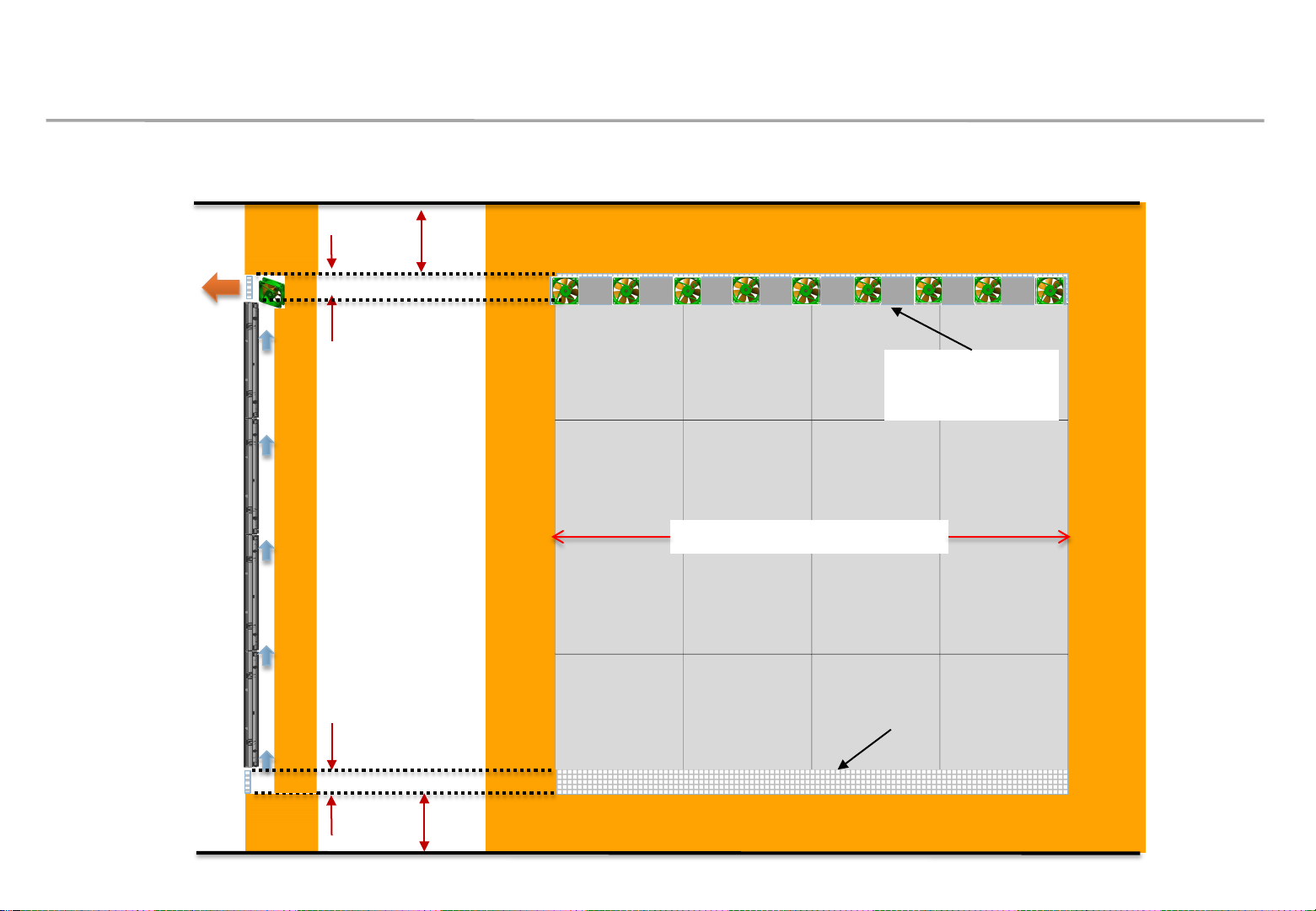
2. Check Point about the Radiant Heat– with Fan
Example of minimum spacing and fan allocation for recessed installation
Min condition: 0mm (set ~ ceiling)
Recommended condition : 500mm
Essential cond. : more than 30mm of 100% opening rate
Other parts except
for FAN area should
Samsung Electronics
be sealed
WALL
Essential cond. : more than 30mm of 100% opening rate
Min condition: 0mm (set ~ floor)
Recommended condition : 500mm
left and right should be sealed.
※ Vent and interior finishing work will proceed after screen installation
Air vent area
22
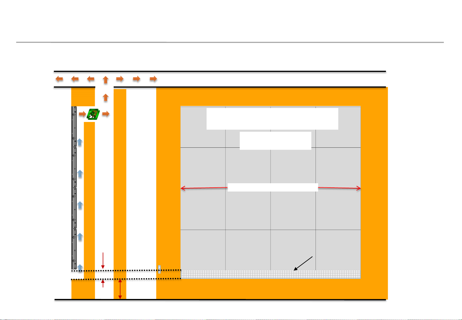
2. Check Point about the Radiant Heat– with Fan
Example of minimum spacing and placement during rear exhaust
Ambient temperature on the back of
the wall should be less than 30 ℃.
Other parts except for
FAN should be sealed.
WALL
left and right should be sealed.
Samsung Electronics
Essential cond. : more than 30mm of 100% opening rate.
Min condition: 0mm (set ~ floor)
Recommended condition : 500mm
Air vent area
23
2. Check Point about the Radiant Heat
◇ IFH-D P2.5 (~35℃ under)
8
7
6
5
4
FHD
3
Vertical
No need for
Samsung Electronics
※ SAMSUNG WALL MOUNT , Full white, back light 7, VENT 70%
UHD
No need for
FAN
2
1
1 2 3 4 5 6 7 8 9 10 11 12 13 14 15 16 17 18 19 20
FAN
Horizontal
24
2. Check Point about the Radiant Heat
◇ IFH-D P4.0 (~25℃ under)
12
Samsung Electronics
※ SAMSUNG WALL MOUNT , Full white, back light 7, VENT 70%
11
10
UHD
No need for
9
8
7
6
5
FHD
FAN
Vertical
4
3
2
1
1~6 7~14 15~16 17~22 23~29 30~32
No need for
FAN
Horizontal
25
2. Check Point about the Radiant Heat
◇ IFH-D P4.0 (25~30℃ under)
Samsung Electronics
※ SAMSUNG WALL MOUNT , Full white, back light 7, VENT 70%
12
11
10
9 170 CFM
8 150 CFM
7
6
5
FHD
230 CFM
210 CFM
UHD
190 CFM
Vertical
4
3
2
1
1~6 7~14 15~16 17~22 23~29 30~32
No need for
FAN
No need for
FAN
Horizontal
26
2. Check Point about the Radiant Heat
◇ IFH-D P6.0 (~25℃ under)
Samsung Electronics
※ SAMSUNG WALL MOUNT , Full white, back light 7, VENT 70%
18
17 215 CFM
16 200 CFM
15 190 CFM
14 175 CFM
13 165 CFM
12 150 CFM
11 140 CFM
10 125 CFM
9 115 CFM
8 100 CFM
7 90 CFM
Vertical
6
5
4
3
2
1
1~10 11~19 20~24 24~29 29~37 38~46 47~48
No need for
FAN
FHD
225 CFM
UHD
No need for
FAN
Horizontal
27
2. Check Point about the Radiant Heat
◇ IFH-D P6.0 (25~30℃ under)
Samsung Electronics
※ SAMSUNG WALL MOUNT , Full white, back light 7, VENT 70%
18
17 345 CFM
16 325 CFM
15 305 CFM
14 285 CFM
13 265 CFM
12 245 CFM
11 225 CFM
10 205 CFM
9 185 CFM
8 165 CFM
7 145 CFM
Vertical
6 125 CFM
5 105 CFM
4 85 CFM
3
2
1
1~7 8~16 17~24 24~34 35~43 44~48
No need for
FAN
FHD
365 CFM
UHD
Horizontal
28
2. Check Point about the Radiant Heat
◇ IFH-DL P8.5 (~25℃ under)
13 165 CFM
Samsung Electronics
※ SAMSUNG WALL MOUNT , Full white, back light 7, VENT 70%
12 150 CFM
11 140 CFM
10 125 CFM
9 115 CFM
8
7
6
Vertical
5
4
3
2
1
No need for
FAN
1~10 11~19 20~24 24~29 29~34
Horizontal
UHD
No need for
FAN
29

2. Check Point about the Radiant Heat
◇ IFH-DL P8.5 (25~30℃ under)
13 265 CFM
Samsung Electronics
※ SAMSUNG WALL MOUNT , Full white, back light 7, VENT 70%
12 245 CFM
11 225 CFM
10 205 CFM
9 185 CFM
8 165 CFM
7 145 CFM
6 125 CFM
Vertical
5
4
3
2
1
1~7 8~16 17~24 24~34
No need for
FAN
UHD
Horizontal
30

3. Preparation for Cabinet Installation
◇ Preparations Before Installation
Samsung Electronics
SLIDING SCREW
Top-Cushion
Box
Fig.1 Box Opening
IB & cable
BottomCushion
LED set
handle
Fig. 2 Handle
① Remove the Box tape at the upper area and then open up the box. (Fig.1)
suburb hole
Fig.3 Bolt Assembly
② Remove the Top–Cushion and hold the handle inside PE-Bag and pull out the set then remove PE bag.
(Fig.2)
③ Assemble four(4) Sliding Screw for installation at the hole located at the outermost part of the Corner. (Fig.3)
31

3. Preparation for Cabinet Installation
Switch Button
Screw
Samsung Electronics
Cushion Top
Fig.4 Check the Screen
Fig.5 Cover Corner
Removal
Fig.6 Cabinet Storage
⑤ Check whether there is any abnormality on the screen by connecting the power cable.(Fig.4)
※ Press the ‘Switch’ button for five(5) seconds after applying the electricity.
If the information screen comes out, press the Switch button to switch the screens on W/Pattern and check the screens.
⑥ Unfasten the screws (total of four[4]) on the Cover Corner area to separate those screws. (Fig.5)
⑦ Put the Cabinet on the Cushion Top so that the LED screen will head upwards. (Fig.6)
32

※ Do not turn on OR display white pattern more than 10 second .
3. Preparation for Cabinet Installation
◈ Reference : Process of Screen check
Power In
Switch Button
Power out
◇ Connect Power Cable to SET.
Use internal pattern to check
dead pixel or any damage with
NO VIDEO
⑦
Push ‘Switch Button’ and
hold it for more than
three seconds.
Push
Switch
Button
Push
Switch
Button
Push
Switch
Button
Push ‘Switch
Button’ and hold
it for more than
three seconds.
①
⑥
Dehumidifying
Push
Switch
Button
Push ‘Switch Button’ and hold it for
④
more than three seconds.
Push ‘Switch
Button’ and
hold it for more
than three
seconds.
⑤
Samsung Electronics
Push Switch
Button
②
Push
Switch
Button
Push
Switch
Button
③
Push
Switch
Button
Push Switch
Button
Push
Switch
Button
screen.
① After turning on power, while showing ‘NO VIDEO’, push ‘Switch Button’ and hold it for more than three seconds.
※[Caution] If you push ‘Switch Button’ and hold it more than 10 secs, factory reset will be done.
② While ‘Dehumidifying’ shows off, if pushing ‘Switch Button’, OSD is shown.
③ Then, OSD, gray, dark red, dark green and dark blue are shown sequentially, whenever ‘Switch Button’ is pushed.
④ In order to go to ‘NO VIDEO’, while OSD is showing, push ‘Switch Button’ and hold it for more than three seconds.
⑤ If brighter patterns are needed, hold ‘Switch Button’ for more than three seconds from gray, dark red dark green or dark blue patterns.
⑥ Then, full white, full red, full green and full blue are shown sequentially, whenever ‘Switch Button’ is pushed.
⑦ Pushing ‘Switch Button’ and holding it for more than three seconds makes it go to ‘NO VIDEO’.
33

3. Preparation for Cabinet Installation
Samsung Electronics
⑧ Attach the PET Sheet and assemble Cover PCB for the Cabinet that is located at the
exterior.
※ PET Sheet & Cover PCB should be at the boundary of whole screen. (Blue area at the exterior of Fig.1)
※ Attach PET Sheet as shown below.(Fig.3), The areas where there is no tape should guide the LED module.
※ Assemble the Cover PCB as shown below.(Fig.4)
No Tape
0~0.5mm
PET-Sheet
Fig.3
Fig.4
Fig.1 Attach point of
Sheet PET
Fig.1 Attach point of
Sheet PET
Fig.1 Sheet PET/ Cover PCB
34

4. Frame Installation
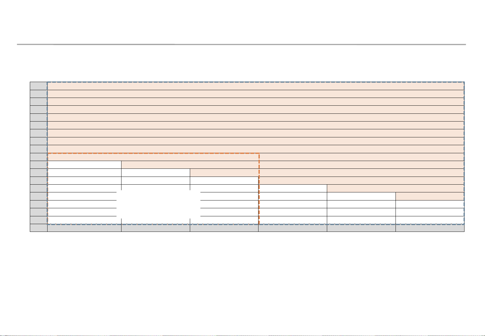
① Frame Kit Composition
Samsung Electronics
No. Item
ⓐ
ⓑ
ⓒ
ⓓ
ⓔ
ⓕ
ⓖ
ASSY BRACKET SIDE
ASSY BRACKET MIDDLE
ASSY BRACKET CENTER
ASSY BRACKET JIG
ASSY SLIDING SCREW
ASSY ANCHOR SCREW
MANUAL-INSTALL
VG-LFH81SWD
8x1 8x2 8x3
Units
2 2 2
6 6 6
2 2 2
1 2 2
48 96 144
20 30 40
1 1 1
VG-LFH82SWD VG-LFH83SWD
Units Units
a
b
b
b
c
b
b
b
a
d
f
g
e
M5,L65, Anchor screw
ⓗ
ⓘ Wrench 1 1 1
Size of the installation Screen
Service JIG
(mm)
1 1 1
720x3840 1440x3840 2160x3840
h
i
35

4. Frame Installation
Samsung Electronics
② Put the ⓐBracket Side the end of the left side and then fasten the screws to install.(Fig.2)
※ After fastening one(1) screw, use the device for vertical positioning to set up straight vertical alignment. Then fasten up the remaining
holes. (Refer to Page 25 for the Precautions for fixing the Screws)
Order of Fastening the Screws (No. 1 → No. 2 → No. 3 ). (Fig.1)
ⓐ Bracket Side is located at 12mm of the end line of the screen. (Fig.3)
a
b
d
b
b
Fig.2 (Location of Componets)
c
25mm 이상
Min. 25mm
b
b
b
a
Min.
12mm
a
Fig.1 (Order of Work)
Min. 12mm
Fig.3(Distance between
Screen and Bracket side)
36

4. Frame Installation
Samsung Electronics
③ Install ⓑBracket Middle.
※ First, check the Hole to fix the ⓒ JIG. [Fig.1]
※ Second, Mount the ⓒ JIG inside the Bracket Hole and fasten up four(4) Screws [Fig.2]
※ Third, fasten the ⓑ Bracket Middle using Screws. [Fig.3]
※ Warning. ⓐ,ⓑand ⓒ sides should be attached,
and the three(3) sides of Wall/Frame side/Jig side should be parallel.[Fig.4]
④ Install ⓑBracket Middle in the same way (from left to right)
※ Install Bracket Center at the center of Frame KIT.
a
Wrong Installation(X) Correct Installation(O)
Wall
ⓐ,ⓑ,ⓒ
ⓓ
Fig4. Maintain the Parallel Frame
b
b
b
c
b
b
b
a
Fig1. Check the Hole
Fig2. Fix the Jig (Screw)
d
Fig3. Fasten the Screw Fig.5 (Location of Components )
37

4. Frame Installation
Samsung Electronics
◇ When installing three or more ASSY BRACKETs, adjust their levels because they may be
distorted by walls or structures.
– After installing three or more ASSY BRACKETs, place another
ASSY BRACKET horizontally on them and measure if there is a
height difference among them. If a height difference is found,
adjust the Z-Bolt heights of ASSY BRACKETs to make them level
with each other.
– Adjusting the heights
1. To adjust the Z-Bolt height of the frame, first remove the washer.
2. After removing the washer, use a wrench (28 mm) to adjust the
Z-Bolt height.
38

4. Frame Installation
Samsung Electronics
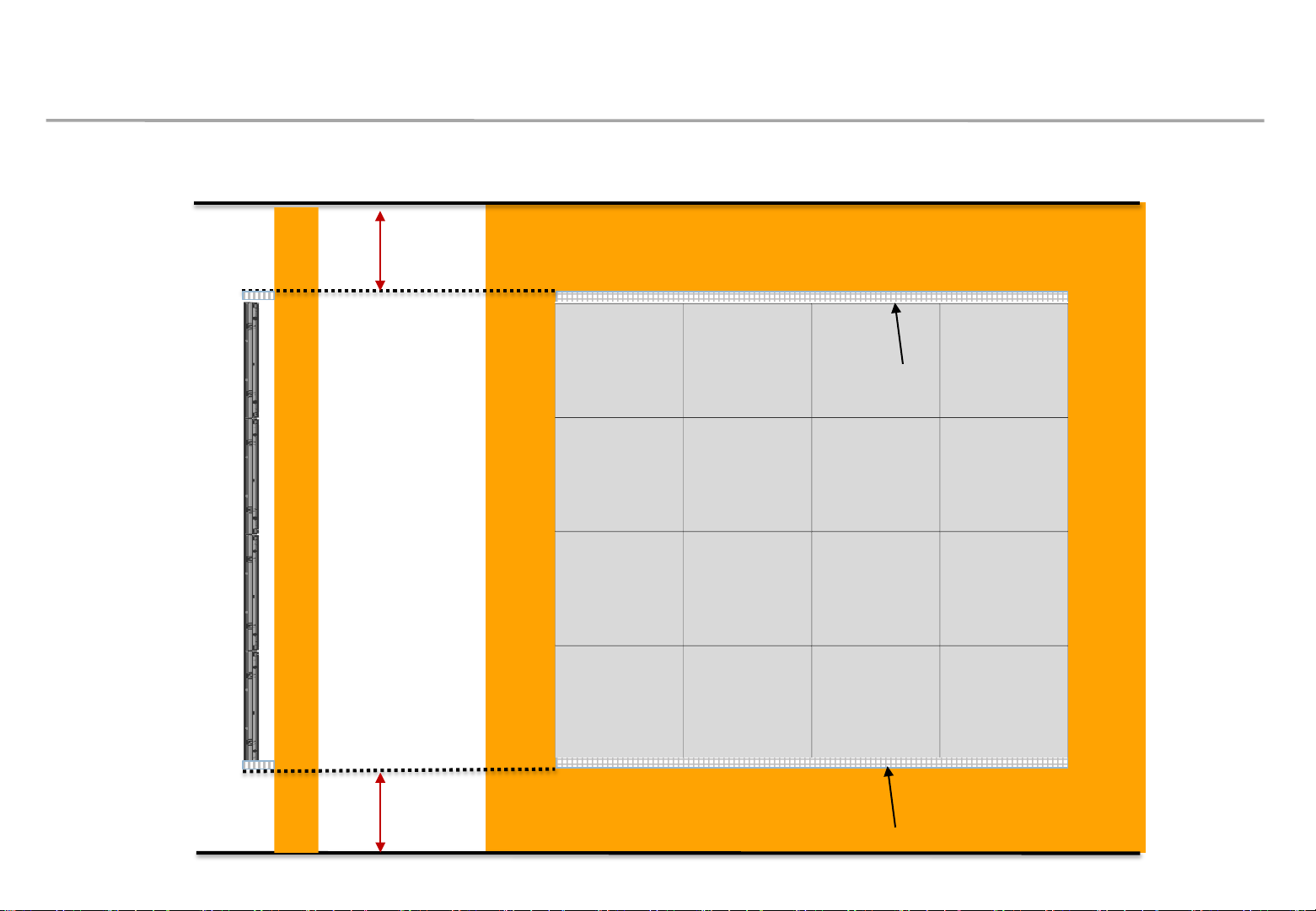
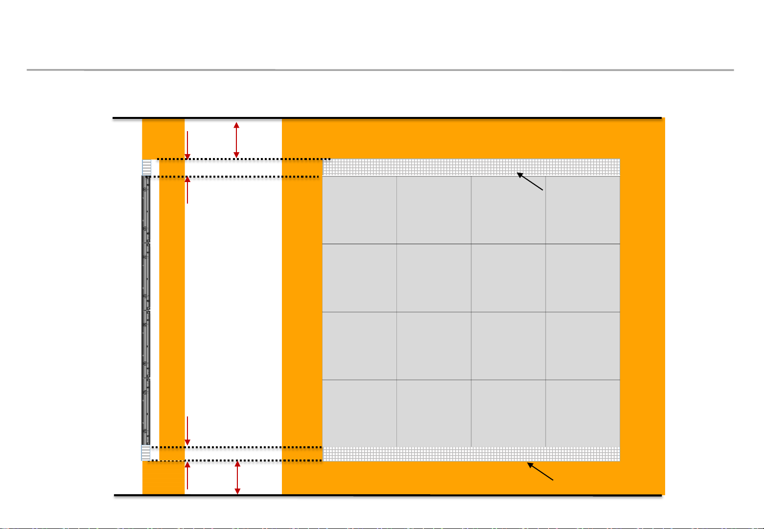
⑤ After installing Bracket Center, install cabinets on the bottom line.. [Fig.6]
⑥ When the cabinet installation is finished, slide the LED modules toward the center and check the
flushes between the cabinets and the LED modules at both ends.
[Fig.7]
⑦ Make the left and right flushes equal, and then adjust the flushes according to the following criteria. [Fig.8]
• If the flush is more than 0.5 mm, move the Frame outward.
• If the flush is less than 0.0 mm, move the Frame inward.
• Adjust the flush each time you install a cabinet additionally. If the flush is 0.0 to 0.5 mm, you don’t
need to adjust.
⑧ When the flush adjustment is finished, install the next Bracket Middle. For the installation method,
refer to Step 2 and the following steps.
⑨ Finally, install Bracket Side.
Fig6. Install cabinets
Fig7. Check flushes
[Fig.9]
Fig8. Adjust flushes
Fig9. Installation of 6x3
39

4. Frame Installation
Samsung Electronics
◇ You can extend a Frame KIT product to any size.
- The VG-LFH82SWD and VG-LFH83SWD models can be extended in both horizontal and vertical directions, for example, to
construct 10 × 6, 10 × 5, or other layouts.
- The VG-LFH81SWD model can be extended only in the horizontal direction.
- When installing the ASSY BRACKET JIG to fix the connection part between ASSY BRACKETs, make sure that 2 people work
together because it is difficult to fix ASSY BRACKET JIG.
(Make sure that one person hold ASSY BRACKET JIG in the fixing position and the other one fasten its screws.)
- When extending the Frame KIT, it is required to install ASSY BRACKET CENTERs between ASSY BRACKET MIDDLEs.
(Recommended specification: one ASSY BRACKET CENTER per three or four ASSY BRACKET MIDDLEs)
Extended installation example
40

4. Frame Installation
◇ Precautions for Fastening the Screws
Samsung Electronics
41

5. LED Display Installation
Samsung Electronics
◇ Fix I/G Location
① Install I/G first on the back side of the Cabinet of each Type. (Fig.1)
※ Location to Install: Locate the I/G at the point 35~40mm below, which is the standard for carving at the right side of the frame,
and then fasten the screws.(Fig.2)
Fig1. Location to Fix the I/G and Order of Installing the Cabinet
I/G
Fig2. Location to Fix I/G
70~80mm
35~40mm
42

5. LED Display Installation
Samsung Electronics
② Adjust the Corners of the Cabinet to each of the cravings to be closer to the Frame.
※ Order of Cabinet Installation (28 Page Fig. 1)
※ Check whether all the six(6) bolts are put into the frame. (Fig.1)
③ Press the upper side of the Frame and assemble so that it slides towards downward diagonal direction
(Fig.2)
④ From the layers above the second floor, insert the Service Jig between each Cabinet,
Marked
Area
remove the Service Jig, slowly lower the Cabinet.
※ Beware not to have the Service Jig touch the LED Module.
※ Check whether the gap between each module widens,
whether the size of the pitch differs every time of installation.
Marked
Area
Marked
Area
Fig.1 Fig.2 Fig.3
(Fig.3)
Sliding Screw
43

5. LED Display Installation
⑤ If modules are too tight, it could be difficult to pick out.
During the installation process,
select some modules and make sure they are easily picked out and reassembled.
Samsung Electronics
44

5. LED Display Installation
Samsung Electronics
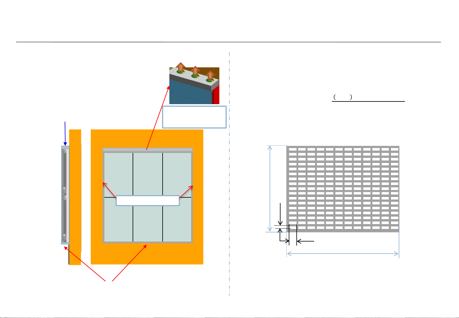
◇ Protection of I/G
To prevent unexpected removing IG box, the Protection Bracket should be attached on left / right
side of the display (Fig.1)
* In case of pocket installation, do not need to attach the protection.
* Keep free space on Top and Bottom for ventilation
Recommended specification for Protection Bracket
① Material: Aluminum or steel, thickness 1.0mm~2.0mm, black coating.
② Dimension: Width 49mm, Length 719.0mm / 1439.0mm / 2159.0mm (same with Frame, Fig.2)
③ Screw hole position: interval 200mm, first screw has distance 130mm to bottom line (Fig.3)
49mm
④ Screw: M4*0.7mm , length 6mm.
Protection
Protection
Fig.1 Protection
VG-LFH81 VG-LFH82 VG-LFH83
Width (mm) 49.0 49.0 49.0
Length (mm) 719.0 1439.0 2159.0
Fig.2 Protection dimension
M4
screw
hole
Fig.3 Screw location
34mm (screw position)
Interval 200mm
130mm
(VG-LFH81SWD 90mm)
45

5. LED Display Installation
Samsung Electronics
◇ Installation Guide of recessed screen
When installing recessed screen, minimal work space is needed from the edge of the
screen.
– In order to finish seam adjustment, fixation parts should be installed on the screen edge. If the parts
are not installed, seam between modules could be made.
– The parts can be fixed on the screen by tools and space for tools are needed on the edge. Though
it may be dependent on your tools, more than 50mm is required in general.
[Fixation parts]
More than 50mm
- The Wall : Holder PCB, Cover PCB
- IFH/IFJ/IER/IFR : Cover PCB
Left work space
Screen
Cabinet
Front View
Top View

5. LED Display Installation
◇ Installation Guide of recessed screen
Work space should be finished with detachable material for service.
– Work space more than 1mm should be secured for safety of the screen.
Be cautious of safety of the screen while detaching and attaching finishing material.
– Top and bottom materials should have enough ventilation hole.
If there is enough heat dissipation space behind the screen, it can be omitted.
– Finishing materials is recommended to have same pattern and material as the wall.
– If metal parts of the screen is shown from the side of it, finish it with black tape.
Detachable
Samsung Electronics
Screen
Front View
Top View
More than 1mm
※ Because wall is not flat perfectly, difference from wall
finishing material and the screen could be made.
In order to prevent it, each part should be designed,
manufactured and constructed.

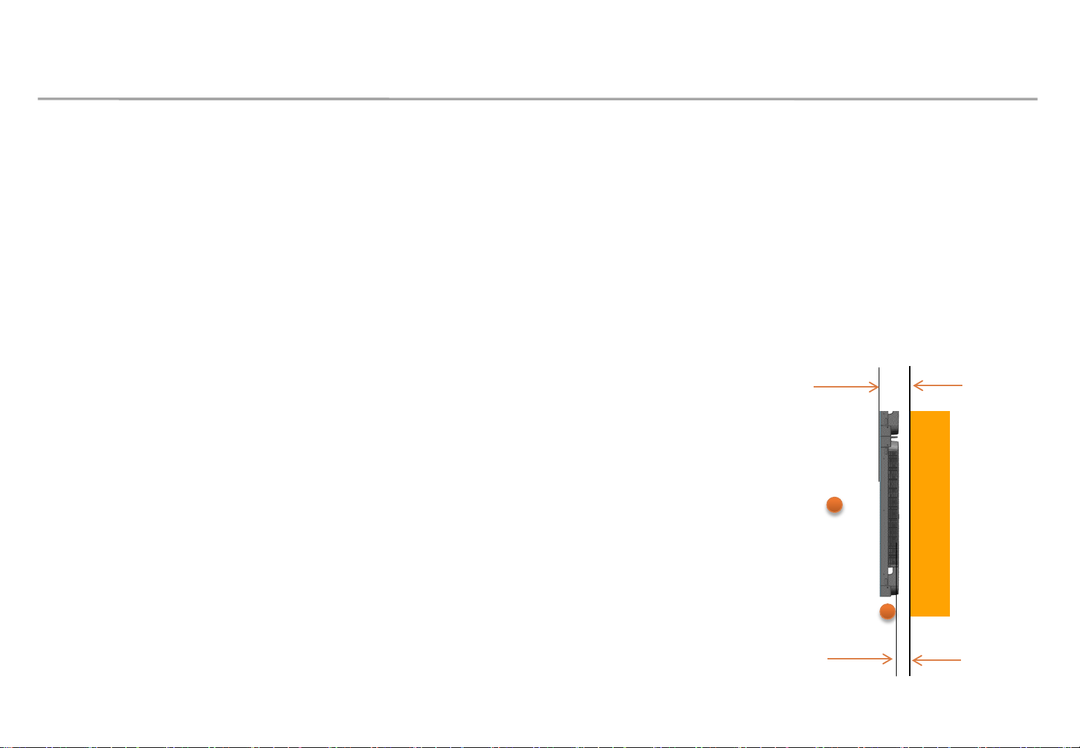
SBB-SNOWJAU / SBB-SNOWJMU
6. S-BOX Installation and Connection
Samsung Electronics
• S-BOX Installation Precautions
① Product recommend installing this product in a standard 19-inch server rack.
※ When connecting two or more times for the purpose of using multi-link HDR, install it on the ground shielded
rack and use it. (SBB-SNOWJMU model)
② Install ventilation opening, do not install the vent by turning it sideways or upside down
③ When installing the product, do not block the air vent on the top to prevent the product from overheating
④ When installing multiple Sbox, Install at least 1U (44.45mm) or more apart from the ventilation openings on the top
of the product
⑤ When installing on a wall, keep all distances between the wall and the top, bottom, left, right sides of the product at
least 10 mm, and also keep the distance between the wall and the ports on the back of the product at least 50 mm
for cable connection.
⑥ Make sure that the ambient temperature inside the rack mount does not exceed 35°.
⑦ Take care not to allow liquid foreign objects to enter the ventilation
openings on the top of the product
48

6. S-BOX Installation and Connection(Only SBB-SNOWJMU model)
• How to install when use Multi Link HDR function
Product recommend installing this product in a standard 19-inch server rack,
please refer 36 page about basic installation guide.
① Please open rubber plug of Multi Link HDR port.
Multi Link HDR Port
② Connect the connector of the cable of Multi Link HDR to
the Multi Link HDR port of each S-BOX.
(Refer 38 page about Cable)
(※ Note : Connect the connector’s structure to face up)
③ Menu – Picture – LED HDR – Multi Link HDR Settings –
ON
④ Set the quantity of S-BOX connected each other. (2/3/4)
⑤ Set S-BOX ID
(※ Note: It is necessary to set the ID not to overlap
between connected S-BOX)
Multi Link HDR Port
Samsung Electronics
UP
SIDE
49

6. S-BOX Installation and Connection(Only SBB-SNOWJMU model)
• Multi Link HDR Cable
Use the appropriate cable according to the quantity of S-BOX connected.
Multi Link HDR Port
Multi Link HDR Port
Samsung Electronics
50

6. S-BOX Installation and Connection(Only SBB-SNOWJMU model)
• FPGA Update Guide when using Multi Link HDR Cable
※ Note : Before update, disconnect the Multi Link HDR Cable from S-BOX.
Samsung Electronics
Factory update method
① Save a SW program called ‘TB-XCKUSBMWWS.bin’ in USB root.
② Connect the USB to S-BOX.
③ Enter Factory mode.
(Remote control ‘mute +1+8+2+Power ON’ in power off state)
④ Select “SVC → UPGRADE” menu.
⑤ Move the cursor to “FPGA UPGRADE” menu.
⑥ Press ‘Enter’ in the remote control.
⑦ Press ‘▶’ button in remote control to start the upgrade.
LSM update method
① Select ‘S-BOX Settings – Software Update’ in LSM menu.
② Select ‘Broswer’ and move to the folder with the FPGA update file
(TB-XCKUSBMWWF.bin + Info.txt)
※ Version in ‘Info.txt’ file should be higher than currently installed
version
③ Select ‘TB-XCKUSBMWWF.bin’ file.
④ Select ‘Update’ button to start the upgrade.
Multi Link HDR Port
※ Note : In case of the sites that are difficult to remove the Multi Link HDR cable, all connected S-BOX
should be AC power off/on after LSM update done. (Must turn off AC power after the update
of all S-BOX are completed)
Check the version of FPGA after update.
51

6. S-BOX Connection
Samsung Electronics
① Input the video signal to the S-BOX. (Input terminal : HDMI, DP)
② Check the signal input from SOURCE STATUS.(RED : HDMI1 , GREEN : HDMI2, Blue : DISPLAY PORT)
③ Connect from the HDBT OUT port of S-BOX to HDBT IN port of Interface Gender using LAN cable.
④ Connect from DATA OUT port of Interface Gender to DATA IN port of the first cabinet using OCM Cable.
⑤ When HDMI UHD Color is set to On, up to the 3840 x 2160 @ 60 Hz resolution is supported
by S-BOX. When HDMI UHD Color is set to Off, up to 1920 x 1080 @ 60 Hz resolution is supported.
※ Menu – Picture – Advanced Settings – HDMI UHD Color : ON
(Default: OFF, S-BOX will be reboot when it is changed.)
⑥ One SNOW-1703U supports only one type
of LED pitch cabinets. Do not connect different types
of LED pitch cabinets.
⑦ SNOW-1703U displays the screen starting
from the upper left cabinet. To view the screen,
connect the HDBT cable to the HDBT OUT 1 port on S-BOX.
• For HDBT signal stability, use the cable above CAT6
STP or FTP level. ( Length 15m~100m )
- Do not use “comb” or “pinstripe” cable.
52

6. S-BOX Installation and Connection
Samsung Electronics
⑧ Instruction for handling HDBase-T cable
Do not use “comb” or “pinstripe” cable
Use HDBase-T cables with 15 meter long at minimum
and 100 meter long at maximum.
Use only HDBase-T Alliance recommended Cables as described below.
HDBase-T Alliance Site :
Do not over bend HDBase-T cables for cable integrity.
Do not tie HDBase-T cables tightly in bundling
https://hdbaset.org/hdbaset-recommended-cables/
★ Orderly Rolled (Recommend) ★ Random Rolled
(Not Recommend)
Do not bundle HDBase-T cables with any AC power cable.
53

6. S-BOX Installation and Connection
⑧ Instruction for handling HDBase-T cable
EMI sources: Keep the cable away from electromagnetic interference environments such as high-voltage
electrical cables, electric motors (such as elevators or refrigerators), fluorescent, light-fixtures and so on
Minimum distance between HDBase-T and AC power cables
: Keep the cable at a distance of at least 12” (=30.48cm) from AC power cables
HDBase-T cables can be bundled with up to 4 cables from single S-BOX.
Do not use RJ45 coupler.
Samsung Electronics
54

6. S-BOX Installation and Connection
⑨ Instruction for trimming HDBase-T cable on site.
STP RJ45 shielded Plug. RJ45 Connector should be CAT6 or CAT7 shielded RJ45 and load bar.
Load bar
Insert conductors into the plastic loader : Using the standard wiring scheme shown here (T-568B), insert
the conductors into the plastic loader piece of the R-J45 connector. The plastic loader is necessary because
the thickness of CAT 6 cable does not allow it to sit flat in an RJ-45 connector like in normal CAT 5.
Samsung Electronics
Load bar and Drain wire
Wires aligned with Load bar
55

6. S-BOX Installation and Connection
⑩ Instruction for trimming HDBase-T cable on site.
Slide the plastic loader down the cable : Slide the plastic loader down the cable as close to the base as
possible.
Cut all conductors Using the wire cutters, cut all conductors leaving approximately 0.5” remaining.
Case 1) Cable with drain wire : See next page Case 2) Cable without drain wire: Use copper foil to touch
on the connector shell as below
Samsung Electronics
Touch on the Al foil or Braid
Copper foil
Connector shell
56

6. S-BOX Installation and Connection
⑩ Instruction for trimming HDBase-T cable on site.
Flip the drain wire up onto the RJ-45 connector Flip the drain wire up onto the RJ-45 connector. Clamp the
strain relief down on the purple jacket of the BC-HDKat6a cable using the pair of pliers.
Solder the drain wire to the metal casing of the RJ-45 connector : Solder the drain wire to the metal
casing of the RJ-45 connector and cut off the excess using the wire cutters. Verify the continuity of the
conductors and the shield using a cable tester.
Recommendation) Drain wire soldering + Copper foil
Samsung Electronics
57

6. S-BOX Connection (Redundancy)
Samsung Electronics
① If Redundant Spec should be used,
Connect from DATA IN port of Interface Gender to DATA OUT port of the last cabinet by using OCM Cable.
• For HDBT signal stability, use the cable above CAT6
SFTP level. ( Length 15m~100m )
- Do not use “comb” or “pinstripe” cable.
58

6. S-BOX Connection (Panel Setting)
① S-Box Initial Image Setting
• First S-Box Default Image Setting is optimized to LH015IFHSAS
• Image Setting will be automatically changed when LED Display is connected
• For optimized image setting, Please connect S-box to LSM
• LED Display should be connected to HDBT1 port
• Image setting will be set according to Master Cabinet connected to HDBT1 port
* If you don’t connect Sbox to LSM, Image can be unnatural.
Samsung Electronics
Control PC
(LSM)
Ethernet
S-box
HDBT
Interface Gender
Vx1+Ethernet
Cabinet 1
(Master)
Vx1
……………
<connect screen>
Cabinet N
59

6. S-BOX Connection (Grouping)
S-Box Grouping is a function used to configure a single screen using multi S-Box.
If you configure one screen with a single S-Box, do not use this function !!
When S-Box Grouping is set up, the quality improvement function(LED HDR) does not work.
Samsung Electronics
60

6. S-BOX Connection (Grouping)
② S-Box Grouping Activate
Remote controller [HOME -> Video wall -> On]
Samsung Electronics
[CAUTION]
1) Before changing S-Box Grouping in LSM, Input source resolution should change to S-Box
recommended resolution
2) If input source is not supported resolution, screen noise could occur.
Off video wall function and change input source frequency to 50~60Hz
※ LSM released 17.6 offer S-Box Grouping, Check LSM Version
61

6. S-BOX Connection (Grouping)
③ PC Frequency Change Method
Right button → Select Image Resolution → Advanced Option
Monitor Tap → Screen Frequency 60Hz
Samsung Electronics
62

6. S-BOX Connection (Grouping)
④ S-box Grouping support resolution
Samsung Electronics
63

6. S-BOX Connection (Grouping)
④ S-box Grouping support resolution
Samsung Electronics
64

6. S-BOX Connection (Grouping)
⑤ Picture menu setting
Both “Dynamic Contrast” and “Black Tone” should be off when using S-Box Grouping, since it may causes a
color difference between S-Box.
Menu → Picture → Advanced Settings,
- Dynamic Contrast : default “Medium” → Off
- Black Tone : default “Darker” → Off
Samsung Electronics

SBB-SNOWJAU / SBB-SNOWJMU
Eco Image Enhancer
*
6. S-BOX Connection (Grouping)
Samsung Electronics
⑤ Picture menu setting
When using S-Box grouping, you must set Picture mode to Calibration. Calibration mode deactivates Contrast
Enhancer, Black Tone, Auto Motion plus function so that there is no screen difference between S-Box.
In addition, change the option in other picture modes as follows table.
Picture Setting Option
Picture Mode Calibration
Advanced Settings Picture Enhancer Off
LED Picture Size Output Resolution UHD
Inverse Tone Mapping Off
Picture Mode
Dynamic Peaking Off*
LED HDR
Off
If Multi link HDR is used, the Dynamic Peaking must turn “On”.
Color Mapping Off
Picture Option Color Tone Off

6. S-BOX Connection (Service Port)
Service Port is used for check full screen, when product fail
As follows, only using compatibility monitor
■ Service port monitor: LH**PMF, LH**PHF, LU28E590DS , LU24E590DS
[CAUTION!] SERVICE PORT can be used service
Service monitor flicker is unrelated to LED Screen
※ If you use LH**PMF, LH**PHF , Change “UHD Color” On
Samsung Electronics
67

7. Settings and How to Use
Samsung Electronics
7-1 Control Program for PCs
LSM(LED Signage Manager)
• LSM Download : Samsung Display Solutions (https://displaysolutions.samsung.com)
Samsung Display Solutions > SOLUTIONS > SOFTWARE SOLUTIONS > LED Signage Solution > LED Signage Manager
※ Partner login is necessary for program download
68

7. Settings and How to Use
7-1 Control Program for PCs
Network IP Setting by USB Configuration File
Samsung Electronics
(※ S-Box(JAU and JMU only) supports since v1050.0)
This is how to set the network information of S-Box with USB
configuration file instead of network IP setting tool.
1. Saves the network information to be configured in the file 'tizen
_netconf.toml'.
2. Copy the file 'tizen_netconf.toml' to USB memory.
3. When you plug the USB memory into the USB port on the S-Box,
it is automatically set.
4. If the IP settings are successful, the LSM and S-Box are normally
connected and the execution result can be viewed through the
'tizen_netconf_result.log' file that is automatically generated in
the USB memory.
tizen_netconf.toml
[network]
device_name = "SNOWBOX“
ip_v4 = "192.168.100.10“
gateway = "192.168.100.1“
subnet = "255.255.255.0“
dns = "192.168.100.11“
[magicinfo]
ip_v4 = "127.0.0.1“
port = 7001
ssl = false
[pc_connection]
mode = "LAN" #LAN : RJ-45, Serial : RS232C
#this is a comment
[★ Notice!] If you plug the USB memory where the file 'tizen_netconf.toml'
is stored into the S-Box, the IP is automatically set. Please rename or delete
the setting file after the configuration is completed.
69

7. Settings and How to Use
7-1 Control Program for PCs
Network IP Setting Tool
Samsung Electronics
Execute : [Start] – Program – Samsung – LED Signage Manager – Network
Configuration
1. Connect PC and Sbox with RS232C Cable, select connected
SerialPort(COM*). And click “open” button.
2. Default ID of SBox is 1.
3. Enter IP, SubnetMask, Gateway, DNS of S-box, and click “Apply”
button.
4. Check the result of connection and status of MDC Protocol.
5. When IP address is normally setup, “Change Type to RJ45” button is
appear. If LSM and SBox is connected successfully, click “Change Type
to RJ45”. Then, PC connection with s-box is changed to RJ45 from
RS232.
[★ Cautions!] Recommend to use static IP address for the S-Box.
If DHCP is used, IP address is changed automatically and LSM can be
disconnected.
The 192.168.10.x band is used for internal communication of the LED Cabinet.
Please use IP another IP band (except 192.168.10.x band)
Do not assign the temporary IP, assign the S-Box IP (1 EA) through IT
manager.
1
2
3
4
70

7. Settings and How to Use
7-1 Control Program for PCs
LSM(LED Signage Manager)
• Software that adjusts the LED Cabinet Layout in Remote
Samsung Electronics
1. PC and S-box should be connected through Ethernet connection.
2. S-box is connected to Interface Gender using HDB-T Lan Cable
3. Interface Gender is connected to the first LED Cabinet using OCM cable.
4. LED cabinets are connected in daisy chain method using OCM cable.
S-box
HDBT
Vx1+Ethernet
Cabinet 1
Cabinet 4
Ethernet
Control PC
Interface Gender
Vx1
Cabinet 2
Vx1
Vx1
Cabinet 3
71

7. Settings and How to Use
7-1 Control Program for PCs
LSM(LED Signage Manager)
• Start– Login Page
1. If the LSM gets operated for the first time, the
page to set the password will appear.
2. To set the password, users have to input the
same password two times and then click the
“Start” button.
3. If the user does not want to use a password,
then please select “Don’t use password” option.
Samsung Electronics
Then, password input would no longer be
required whenever the LSM gets operated.
72

7. Settings and How to Use
7-1 Control Program for PCs
LSM(LED Signage Manager)
• New Connection
1. To add connection information, you can either use
Search function or input the IP address by yourself. If
you click on the Search button, the IP addresses
available on S-BOX in the same network will appear. If
you know the IP address of the S-BOX, then you can
input the address by yourself.
2. If you click Add button, the relevant connection
1 1
1
Samsung Electronics
1
2
information will be added on Setup and Connect.
3. Users can select the Model Type of S-Box. There are
three(3) Model Types (Without Cabinet IP / With
Cabinet IP(FHD) / With Cabinet IP(UHD)).
2
73

7. Settings and How to Use
7-1 Control Program for PCs
LSM(LED Signage Manager)
• New Connection-Connect
1. When you are using the previous version of S-BOX, select
“Without Cabinet IP” option.
2. If you are using UHD S-BOX, select “With Cabinet IP
(UHD)” option. You should designate the IP Address of
the LED Cabinet by each port. Set the number of units
Samsung Electronics
[★ Cautions!] Recommend to use static IP address for the LED devices.
If DHCP is used, IP address is changed automatically and LSM can be
disconnected.
The 192.168.10.x band is used for internal communication of the LED Cabinet.
Please use IP another IP band (except 192.168.10.x band)
Do not assign the temporary IPs, assign the LED IPs (4 EA) through IT
manager.
connected, and then click “Connect”.
3. If you are using FHD S-BOX, select “With Cabinet
IP(FHD)”. Set the IP Address and the number of units
connected in LED Cabinet, and then click “Connect”.
※ If you have already set the IP on the Cabinet, check “Connect with
existing settings” option.
※ For the case of UHD, if you are going to use only some of the
four(4) ports, input the IP Address only for that particular Group
relevant with your use.
※ Should be different than S-Box / Should be different for each groups
※ Should be same as S-Box
74

7. Settings and How to Use
Samsung Electronics
7-1 Control Program for PCs
[★ Cautions!]
LSM(LED Signage Manager)
• Main Window-Home Window
1. Home Screen : Information of the connected device, input source, cabinet composition, and error device are shown.
The network port 1515, 48484, 48485 and 58585 are used for internal
communication between S-BOX and LED Cabinet.
It should be include the firewall or network exception if customer used secured
network.
75

7. Settings and How to Use
7-1 Control Program for PCs
LSM(LED Signage Manager)
• Main Window-Home Window
1. Input source: Input source, resolution, connection time of
S-BOX are shown.
2. Cabinet Layout : Layout, number of units, number of
Samsung Electronics
connections and number of disconnections in all LED
cabinets are shown.
3. Faulty device: ID of the LED cabinet in error status and the
content of the error are shown.
76
7. Settings and How to Use
7-1 Control Program for PCs
LSM(LED Signage Manager)
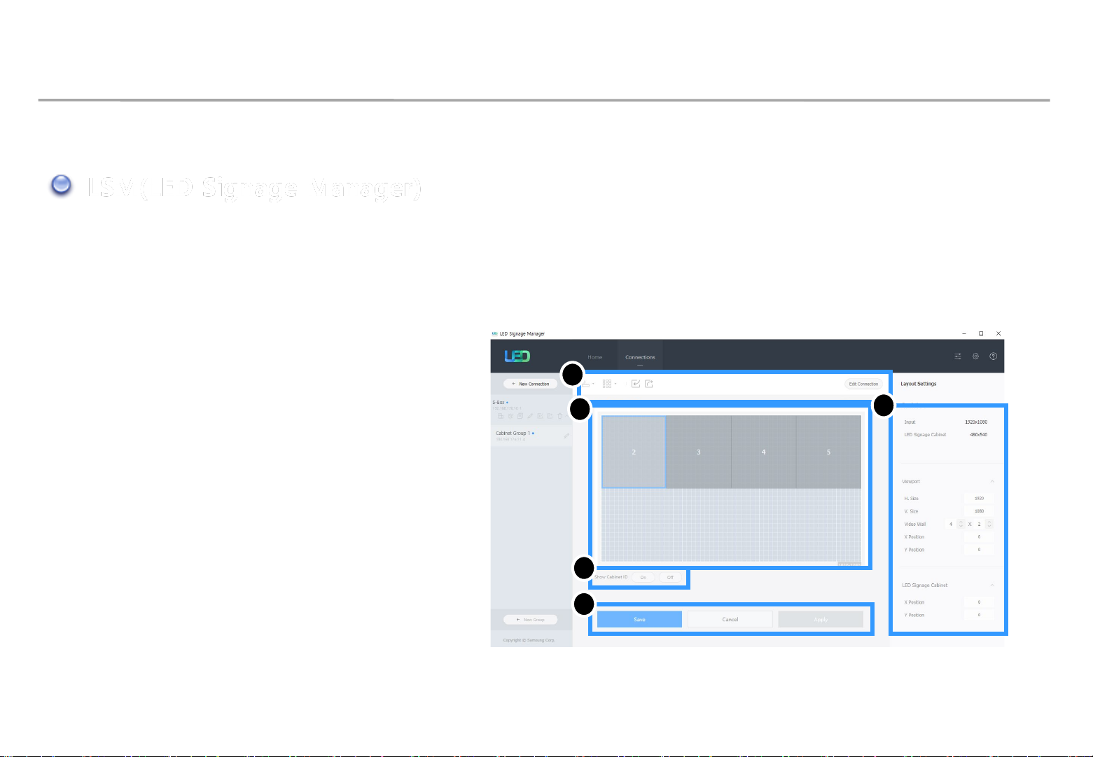
• Main Window-Edit Connection Layout Window
1. Connection layout: The location and the layout
of each LED cabinet are adjusted in the output
source area of the S-BOX.
2. Feature View: Edit button to modify the
connection information and LED cabinet
automatic alignment function, etc. are provided.
3. Device Information/Setting View:
The LED cabinet information is shown for in
three different categories below:
2
1
Samsung Electronics
3
(i) Resolution: Resolution information of the
input source
(ii) View Port: Width/Length size, Video wall
matrix, x/y coordinate settings
(iii) LED Signage Cabinet: x, y location of LED
cabinet
4. Show ID: IDs of each will be shown in all
connected LED cabinets when this option is
selected.
5. Save/Apply and Cancel
4
5
77

7. Settings and How to Use
7-1 Control Program for PCs
LSM(LED Signage Manager)
• Main Window-Connection Window
1. Device connection list view:
Check S-BOX composition, modify and
delete S-BOX connection, show by each
LED Cabinet Group
2. Connection layout (View Port):
Check the location and layout of each
LED cabinet
1
3
Samsung Electronics
6
4
2
3. Category View:
Home / Connections tab and settings
4. Device Information/Setting View:
Change S-BOX settings (screen settings,
etc.)
5. Sub Information View: Displays:
Monitoring log, S-BOX and LED cabinet
information
6. Link of LED Configurator, Preference,
Help files
5
78

7. Settings and How to Use
7-1 Control Program for PCs
LSM(LED Signage Manager)
• Main Window-Connection Window - Device Information/Setting View
1. Basic :
. Power On/Off, Change input source, Screen
Mute / Freeze
2. Picture
. Change Picture Mode, Brightness / Contrast
/ Sharpness, Color, Tint(G/R), Color Temp(K),
Gamma, White Balance adjustment
3. Picture Options
. Color Tone, HDMI Black Level, Film Mode,
etc.
Samsung Electronics
4. Advanced Settings
. Adjust Black Tone, Flesh Tone, Color Space,
etc.
5. System
. Auto Power On/Off, Standby Control
Clock, Timer, System Restart Interval
Software Update function
79

7. Settings and How to Use
7-1 Control Program for PCs
LSM(LED Signage Manager)
• System - System Restart Interval (Cont’d.)
- For product stability, S-Box reboot every week.
- Default setting : 4:00am ~ 5:00am, Monday
- To change rebooting time, Use System Restart Interval of LSM
Samsung Electronics
※ Check LSM time correct, or S-Box will reboot succrently
80

7. Settings and How to Use
7-1 Control Program for PCs
LSM(LED Signage Manager)
• System - System Restart Interval
- If reboot function is unnecessary, go to factory menu and off the weekly boot
: Factory – Control – LFD Option – Weekly Reboot : ON → OFF
Samsung Electronics
81

7. Settings and How to Use
7-1 Control Program for PCs
LSM(LED Signage Manager)
• Main Window-Connection Window - Device Information/Setting View
6. Cabinet Settings (※ Each menu can be supported for some specific models)
. LOD (LED Open Detection) : Check the number of LED Off
(Screen can be blinking when Recheck)
. Pixel RGB Data Reload : Load the Pixel Calibration data to the screen
. Pixel RGB Data Request : Download the calibration data via Cal Reader.
. OnScreen Display : On or Off for “No Video” OSD display on cabinet.
. LED Brightness : Adjust the screen brightness (0 ~ 10)
Samsung Electronics
. Refresh Rate : Adjust refresh rate (Normal or High)
(Some models support only High)
. Software update : Update the cabinet software (Main sw, FPGA, Calibration data)
82

7. Settings and How to Use
7-1 Control Program for PCs
LSM(LED Signage Manager)
• Main Window-Connection Window - Device Information/Setting View
7. Cabinet Calibration
. Perform RGB CC calibration for each module/
Cabinet.
. Calibrate the boundary surface of each module.
. Multiple Selection : Check next page.
. Turn on/off CC. Turn on/off Edge Correction.
Samsung Electronics
. Gradation Calibration : For expert user only.
. Download module calibration data through Batch
Upload/Import/Export.
83

7. Settings and How to Use
7-1 Control Program for PCs
LSM(LED Signage Manager)
• Main Window-Connection Window - Device Information/Setting View
. Cabinet Calibration
└ Multiple Selection
: Calibrate the boundary surface of selected multiple modules. Change offset then brightness is adjusted for edge.
Use Apply button for applying.
Samsung Electronics
84

7. Settings and How to Use
7-1 Control Program for PCs
LSM(LED Signage Manager)
• Main Window-Connection Window - Sub Information View
1. Monitor Window:
Checking MDC communication log and
connected device information available,
able to be extracted via file
2. LED Signage Cabinet:
IC information and Power information of
LED cabinet
Samsung Electronics
3. LED Signage Box:
IP address, MAC address, ID range of LED
cabinet, number of LED cabinet
(all/connected/not connected), serial
number, version information
85

7. Settings and How to Use
7-1 Control Program for PCs
LSM(LED Signage Manager)
• Main Window-Preference
1. Options
number of times the command retried
interval of checking error status
alarm temperature warnings
2. Support
program language
Log data management
notify device error through Mail
Password settings option
Samsung Electronics
3. About Software
the current version of LSM and update
function
86

7. Settings and How to Use
7-1 Control Program for PCs
LSM(LED Signage Manager)
• Software Update
1. Prepare the update SW File
Samsung Electronics
Info.txt
L-IERMWWAC-1001.0
2. Click on the "Software Update" button in "Cabinet Settings" on the LSM menu.
※ For AM3352, update files for LSM and USB are different.
※ A separate tool is required to update the FPGA SW to USB.
L-IERMWWAC-1001.0
FPGAFW-2525218466
FPGAFW.bin
Info.txt
87

7. Settings and How to Use
7-1 Control Program for PCs
LSM(LED Signage Manager)
3. Click the Browse button to select the SW file to update.
Samsung Electronics
Info.txt
L-IERMWWAC-1001.0
※ Never update the "info.txt" file. Causes system failure.
4. Press the Update button to update the cabinet.
FPGAFW.bin
Info.txt
88

7. Settings and How to Use
7-1 Control Program for PCs
LSM(LED Signage Manager)
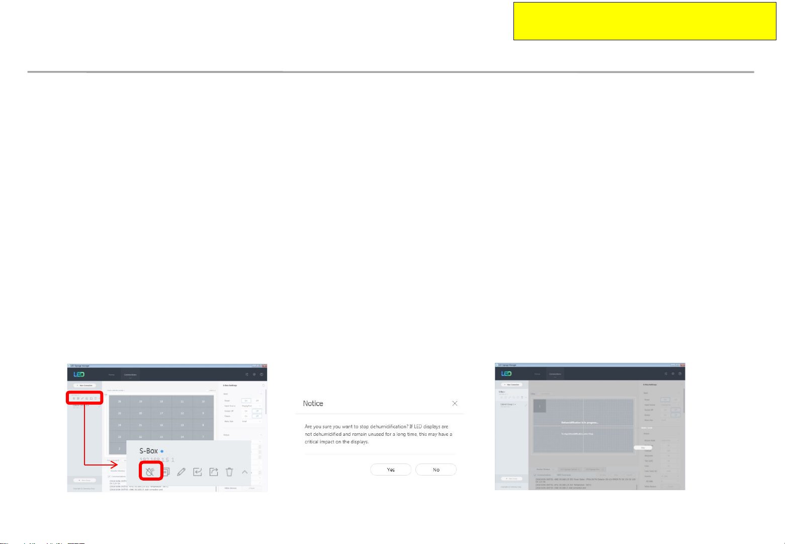
• Dehumidification Mode using LSM
1. The dehumidification mode icon is provided
under the S-Box menu.
2. To turn on dehumidification mode, click the icon.
(Proceed : 24 hours)
Samsung Electronics
3. It is possible to view how long the
dehumidification has been on.
4. To turn off the mode, click the “Stop” button.
89

7. Settings and How to Use
7-1 Control Program for PCs
LSM(LED Signage Manager)
• test pattern using LSM
1. S-Box Test Pattern
- Utilize when installing cabinets (only for test)
*
When the test pattern is turned on / off or the pattern
is changed, background screen may be visible for a
while by overlay layer switching.
Samsung Electronics
90

8. Issue and Solution
Samsung Electronics
◇ Problem Case 1
Rule 1: The 1stCabinet from I/G board must be ID #2 for the LSM Setup
Rule 2: The 1stCabinet from I/G board must be set as Master. The 2ndMaster cabinet is not allowed for the LSM connection.
Situation: After changing Main board or Cabinet, If the original Master cabinet is move the other place,
LSM configuration will be fail because of violation of rule 1.
during the LSM setup it cause a network fail because the 1stcabinet is not ID #2.
HDB-T(LVDS)
OCM(Vx1)
Redundancy
OCM(Vx1)
Master
18 17 14 13 10 9
19 16 15 12 11 8
ID:2 3 4 5 6 7
Re- install
9 11 13 4 18 8
19 10 2 14 16 17
12 3 15 5 6 7
1stCabinet’s ID: 12
Violation of Rule #1
9 11 13 4 18 8
19 10 2 14 16 17
12 3 15 5 6 7
LSM Connection Fail because 1
cabinet is not ID 2
Solution: Do Factory Reset the 1stCabinet
st
91

Master
Master
8. Issue and Solution
Samsung Electronics
◇ Problem Case 1
Rule 1: The 1stCabinet from I/G board must be ID #2 for the LSM Setup
Rule 2: The 1stCabinet from I/G board must be set as Master. The 2ndMaster cabinet is not allowed for the LSM connection.
Situation: After changing Main board or Cabinet, If the original Master cabinet is move to slave cabinet area.
Although the 1stcabinet is set as a Master after doing factory reset, LSM configuration will be still fail
because of violation of rule 2. LSM setup can be start, but can’t be complete because of the 2ndMaster cabinet.
14 13 10 9
12 11 8
2 3 4 5 6 7
HDB-T(LVDS)
OCM(Vx1)
Redundancy
OCM(Vx1)
18 17 14 13 10 9
19 16 15 12 11 8
ID:2 3 4 5 6 7
9 11 13 4 18 8
19 10 2 14 16 17
Re- install
3 15 5 6 7
ID:
2
The factory reset of 1stcabinet is done
From ID 2 to ID13, the LSM connection will
be OK.
but 14
th
cabinet will be connection fail.
Over 14
might be not correct. Because of
nd
2
Solution: Do Factory Reset the 2
th
cabinet the picture
Master cabinet
nd
Master Cabinet
92

8. Issue and Solution
◇ How to do Factory Reset
After checking cable connection order, the cabinet which is not display the proper picture position will be
Wrong positioned Master cabinet. In this case, Do factory reset to change to slave cabinet .
Refer the below guide to do factory reset in front side and backside.
Samsung Electronics
The 1stcabinet is not ID number 2. Because all cabinets
connection are failed.
The 14thcabinet which is displaying the not proper picture
position might be wrong positioned Master cabinet.
Hook
Factory Reset in back side
Press button
over 10 Seconds.
Remove module in
the front
Hook
Set LSM again.
18 17 14 13 10 9
19 16 15 12 11 8
ID:2 3 4 5 6 7
Factory Reset in front side
Remove Cover
Do Factory Reset
Handle
Press hook unlock cover
93

9. Cable/Power Connection
Samsung Electronics
9-1 Cable Connection
• If using 110V/220V, you can connect at most 3 IFH-D(IF040/IF060/IF025) devices.
• Exceeding the recommended maximum number of devices can cause the circuit breaker of the
product to trigger due to overload. SURELY CONNECT the devices less than the recommended
maximum number of devices.
※ No responsible for Samsung Electronics in case of exceeding the recommended maximum
number of devices connection.
• The label info which is attached behind product shows rated power of cabinet and rated current of
outlet.
94

9. Cable/Power Connection
9-2. The caution for Cabinet installation and Cable connection(Full Front)
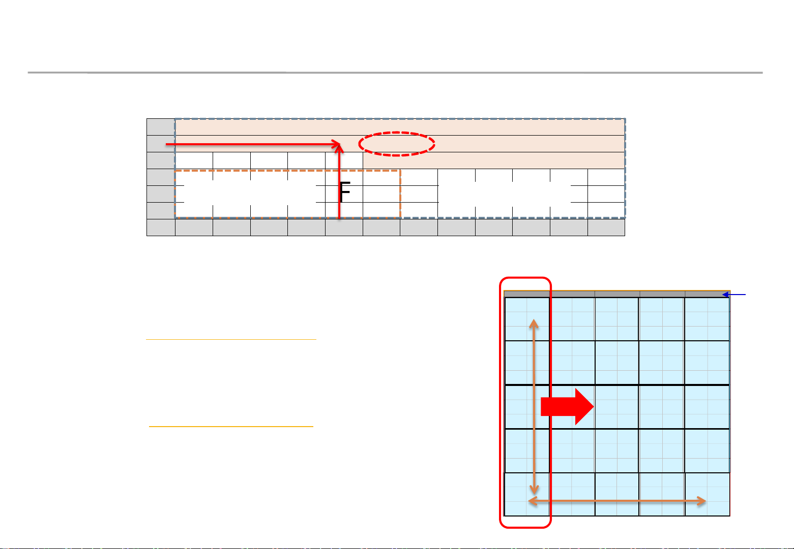
1) The set installation order Must be Left -> Right direction. Because The structure of Wall
mount hole for cabinet installation is downward diagonal direction.
→ The set installation order and The cable connection order are different.
2) After installing cabinets one line is complete, make sure the connection is OK
by connecting OCM/Power cable. Then, Install next line.
( Do not turn on the screen more than 10 seconds)
Samsung Electronics
3) In case of connecting OCM cable upward, Connect OCM cable to Lower set first.
4)
The two output of Interface gender should be connected to First cabinet and Last cabinet each
→ Interface Gender should be installed at Left-Center side of LED wall (refer to page13)
(Within 2~4M compared to first and last cabinet for connecting OCM cable)
95

9. Cable/Power Connection
Samsung Electronics
9-3 The direction for Cabinet installation
1) Installation of First row cabinet starts at the bottom of Left-end.
2) After installing cabinets one line is complete, make sure the connection is OK
by connecting OCM/Power cable. Then, Install next line.
3) From Second row, it starts from bottom to top.
1) 1strow :
Install set form Left-end
Check Gap between module
inside cabinet
2) Connect
Power/Signal Cables
3) 2ndrow :
Bottom to top
Check Gap between cabinets and
whether installed in a straight direction.
4) Same way
96

9. Cable/Power Connection
9-4. Cable Connection : Data flow standard
◎ Connect OCM cable Forward direction
Samsung Electronics
Reverse
Forward
P4.0 (1200X1080)
Reverse
Forward
P2.5 (1920X1440)
P6.0 (800X600)
97

9. Cable/Power Connection
9-5. Apply COVER CAP to POWER IN CABLE of the top cabinets.
Samsung Electronics
COVER-CAP
POWER-IN CABLE
COVER-CAP
8*3 (예시)
98

10. Seam Adjustment
Samsung Electronics
◇ Check and Adjust Seam
① Check whether there is any Black Line between the cabinets in White Screen. (Fig.1)
② Check whether gap, differences occur between each module. (Fig.2)
※ Gap: appears as a black line in every direction.
※ Difference: A bright white line occurs in one direction whereas a black line occurs in the opposite direction.
③ If gap occurs, use module with hand from the outermost corner.
④ If differences occur, disassemble low LED module, and spin the Holder-Magnet using tools to
adjust the height.
※ If the Tool spins 0.5 rotation first, and then spins 36 degrees later, the module height will be moved by 0.1mm. (Fig.3)
Black line occurs in white screen
GAP
LED module 1
CABINET
LED module 2
Tool
Moves 1mm
for each
rotation
Holder Magnet
Tool
(upside down)
Difference
LED module 1
LED module 2
CABINET
Fig.1 Black line Fig.2 Gap/Difference
between Modules
Fig.3 How to adjust Difference
Holder
Magnet
Moves 1mm
for each
rotation
99
 Loading...