

Samsung LH015IFH SERIES, LH020IFH SERIES, SBB-SNOWH3U, LH025IFHSERIES Installation Manual

Samsung Electronics
LED Display
Installation Manual
LH015IFH*** (P1.5)
LH020IFH*** (P2.0)
LH025IFH*** (P2.5)
SBB-SNOWH3U
Ver. 1.0

Samsung Electronics
Table of Contents
1. Product Information and Precautions for Installation
2. Preparation for Cabinet Installation
3. Frame Installation
4. Cabinet + Frame Installation
5. SBOX Connection
6. Settings and How to Use
7. Issue and Solution
8. Cable Connection
9. Seam Adjustment
1
Samsung Electronics
• Frame Kit Composition ( Refer to Page 8 )
1. Product Information and
Precautions for Installation
Frame Kit Composition Note
CY-LFH15FWA 6*3(18 Set)
FHD Installation
for P1.5 Standard
CY-LFH20FWA 8*4(32 Set)
FHD Installation
for P2.0 Standard
CY-LFH25FWA 10*5(50 Set)
FHD Installation
for P2.5 Standard
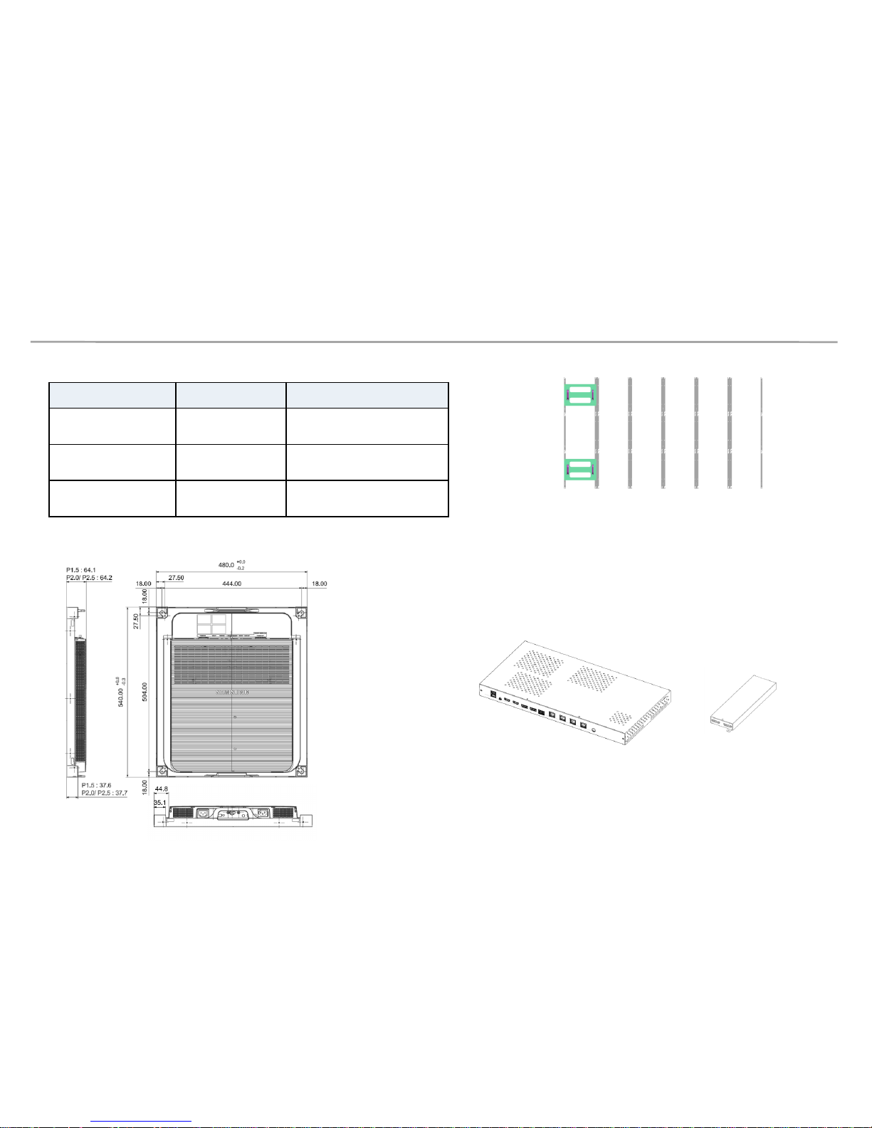
Fig.3 S-Box Fig.4 I/G
(Interface Gender)
• SBB-SNOWH3F/U (S-Box, I/G)
Fig.1 (6*3)
• Cabinet Product Information ( Fig2.)
Fig.2
2
Samsung Electronics
1. Product Information and
Precautions for Installation
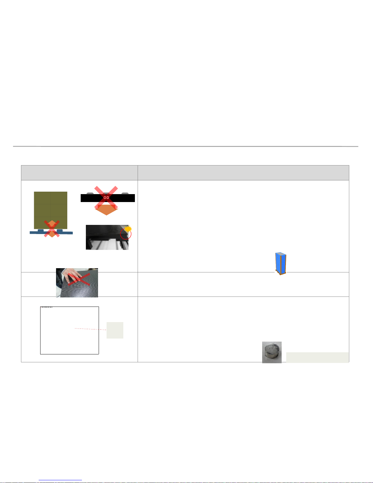
• Precautions for Installation (LED damage)
Image Precautions
[ Beware of Outside Impact, Fall]
▶
Beware not to cause any impact on the LED screen or drop the product on the
floor after the protection gets taken off for installation.
▶
Beware not to fall the back side of the product on the floor or to put on a
vibrating material.
▶
Beware not to have the corner area of LED module be damaged due to the
contact with the outside.
▶
Beware not to put the LED side headed downwards to the floor after the
protection gets taken off for installation.
▶
Beware not to put more than 12 layers.
[Beware of LED Damage due to Static Electricity]
▶
Beware not to touch LED screen with bare hands without putting gloves on.
[Beware of LED Damage due to Metallic Substances]
▶
Beware not to have metallic substances pulled in to the surface due to the
magnetic force on the front side of the LED.
▶
If any metallic substances get drawn in on the surface, please disassemble the
module and then remove the pollutants by using a magnet.
MODULE
Front
MODULE
Metallic
substance
Magnet attached where metallic
substances are attached.
3
Samsung Electronics
1. Product Information and
Precautions for Installation
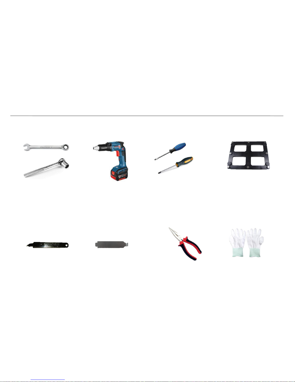
• Preparations for Installation
10.0mm Wrench
LED MODULE JIG
(model name: CY-LJFNAS)
Electric Driver
(-) (+) Driver
Plier
Service JIG
(BH81-00001A)
Holder Magnet Tool
Antistatic
Glove
4
Samsung Electronics
2. Preparation for Cabinet Installation
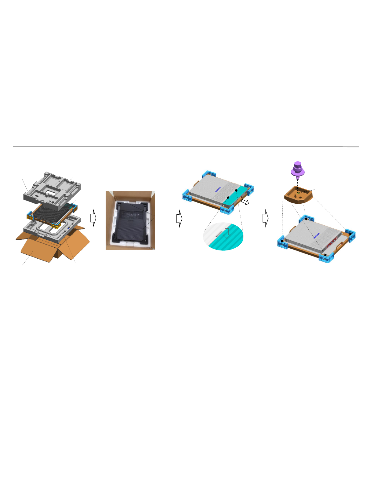
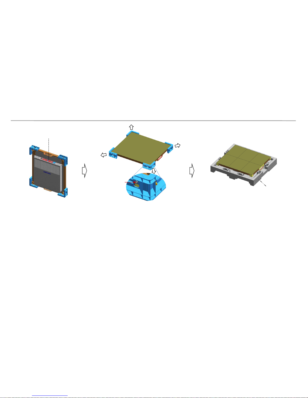
Fig.1 Box Opening
• Preparations Before Installation
handle
Push
Hook Area
Top-Cushion
IB & cable
Bottom-Cushion
LED set
Box
Fig. 2 Handle
Fig.4 Bolt Assembly
Fig.3 Cover Connector
Removal
SLIDING SCREW
(In Exclusive Frame Accessory)
9 Page - ⓓ
Outermost Hole
① Remove the Box tape at the upper area and then open up the box. (Fig.1)
② Remove the Top–Cushion and hold the handle inside PE-Bag and pull out the set then remove PE bag.
(Fig.2)
③ Press the hook area and then bend backwards to separate the Cover-Connector. (Fig.3)
④ Assemble four(4) Sliding Screw for installation at the hole located at the outermost part of the Corner. (Fig.4)
5
Samsung Electronics
2. Preparation for Cabinet Installation
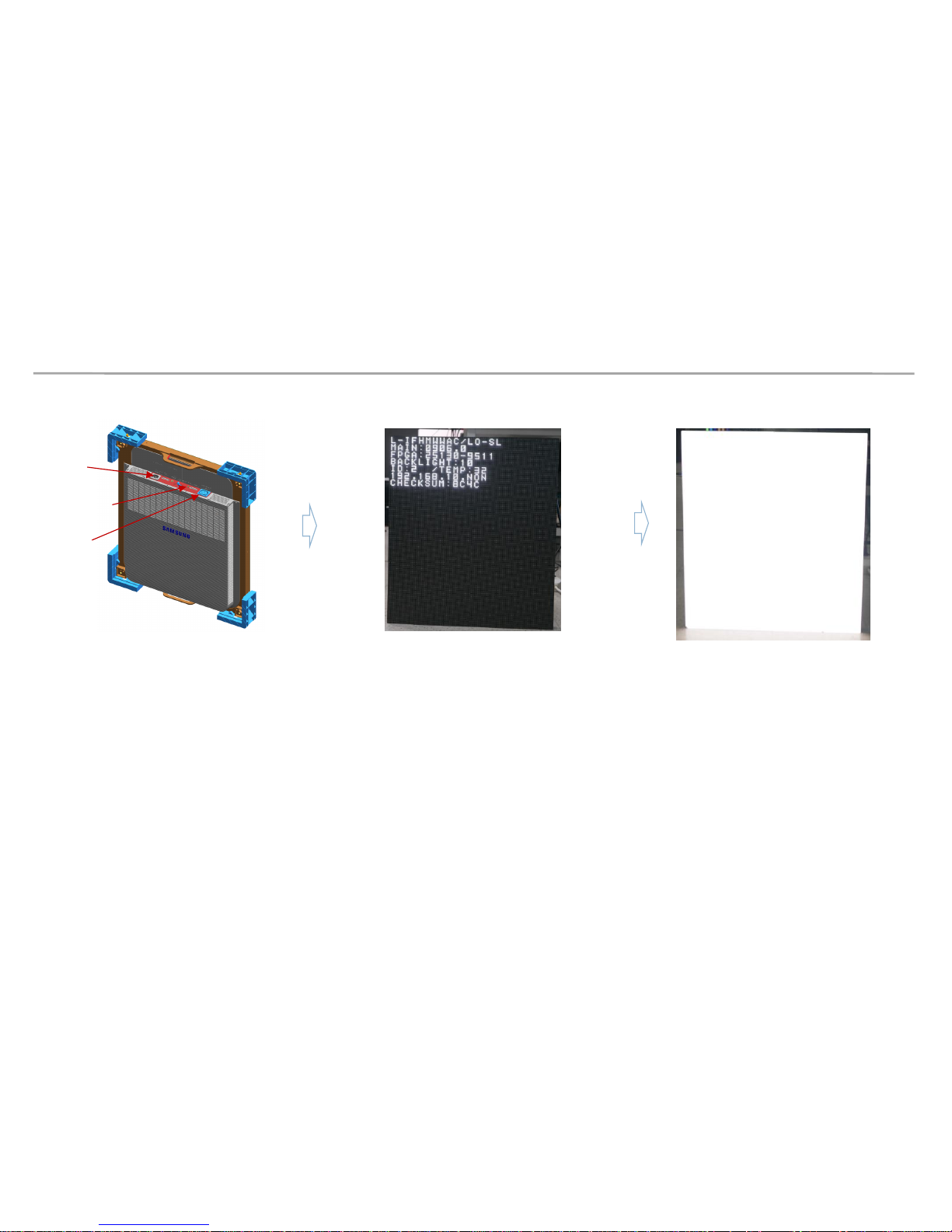
⑤ Check whether there is any abnormality on the screen by connecting the power cable.(Fig.5)
※ Press the ‘Switch’ button for five(5) seconds after applying the electricity.
If the information screen comes out, press the Switch button to switch the screens on W/Pattern and check the screens.
⑥ Unfasten the screws (total of four[4]) on the Cover Corner area to separate those screws. (Fig.6)
⑦ Put the Cabinet on the Cushion Top so that the LED screen will head upwards. (Fig.7)
Cushion Top
Screw
Switch Button
Fig.5 Check the Screen
Fig.6 Cover Corner
Removal
Fig.7 Cabinet Storage
6
Samsung Electronics
◇ Connect Power Cable to SET.
Use internal pattern to check dead pixel or any damage with screen
※ Internal white pattern :
- Turn on Power
- Push Source button 5 seconds and release,
- Wait for display, push one more times. (color rotation : White → Blue → Red → Green)
- Push button for 5 seconds again to exit factory OSD
Switch Button
Power In
Power out
2. Preparation for Cabinet Installation
◈ Reference : Process of Screen check
7
Samsung Electronics
2. Preparation for Cabinet Installation
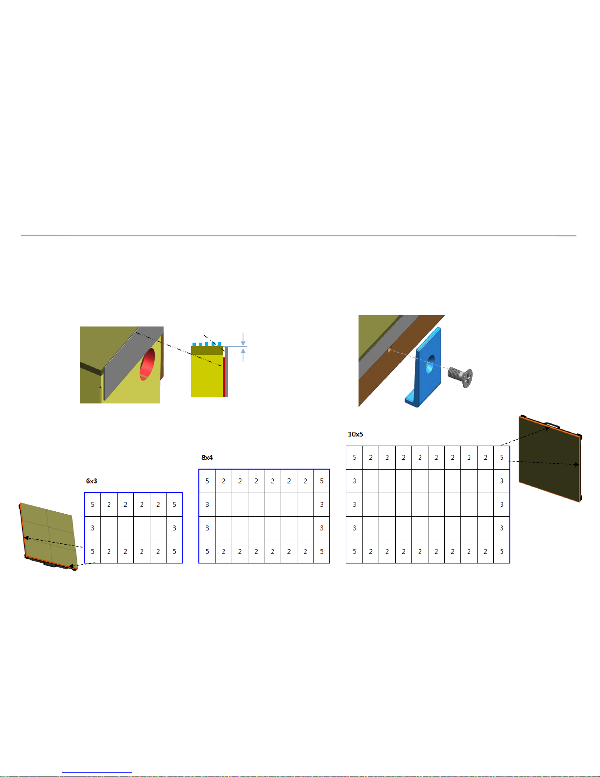
⑧ Attach the PET Sheet and assemble Cover PCB for the Cabinet that is located at the
exterior.
※ PET Sheet & Cover PCB should be at the boundary of whole screen. (Blue area at the exterior of Fig.1)
※ Attach PET Sheet as shown below.(Fig.3), The areas where there is no tape should guide the LED module.
※ Assemble the Cover PCB as shown below.(Fig.4)
Fig.1 Sheet PET/ Cover PCB
Fig.3
Fig.4
PET-Sheet
No Tape
0~0.5mm
8
Fig.1 Attach point of
Sheet PET
Fig.1 Attach point of
Sheet PET
Samsung Electronics
a
a
b
b
b
b
b
c
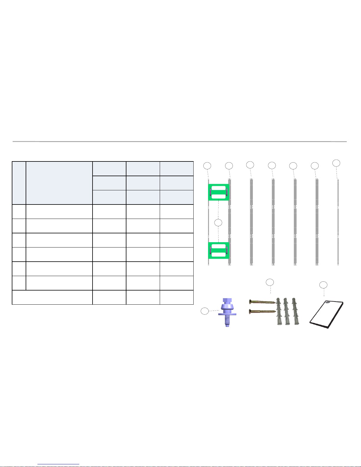
No.
Item
CY-LFH15FWA CY-LFH20FWA CY-LFH25FWA
6X3 8X4 10X5
Units Units Units
ⓐ
ASSY BRACKET SIDE 2 2 2
ⓑ
ASSY BRACKET CENTER
6 8 10
ⓒ
ASSY BRACKET JIG 2 2 2
ⓓ
ASSY SLIDING SCREW 76 132 204
ⓔ
ASSY ANCHOR SCREW 32 50 72
ⓕ
MANUAL-INSTALL 1 1 1
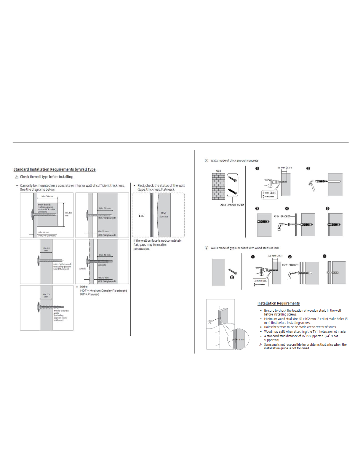
Size of the Installation Screen(mm)
2880X1620 3840X2160 4800X2700
3. Frame Installation
• Frame Kit Composition
d
e
f
9
M5,L65, Anchor screw
Samsung Electronics
3. Frame Installation
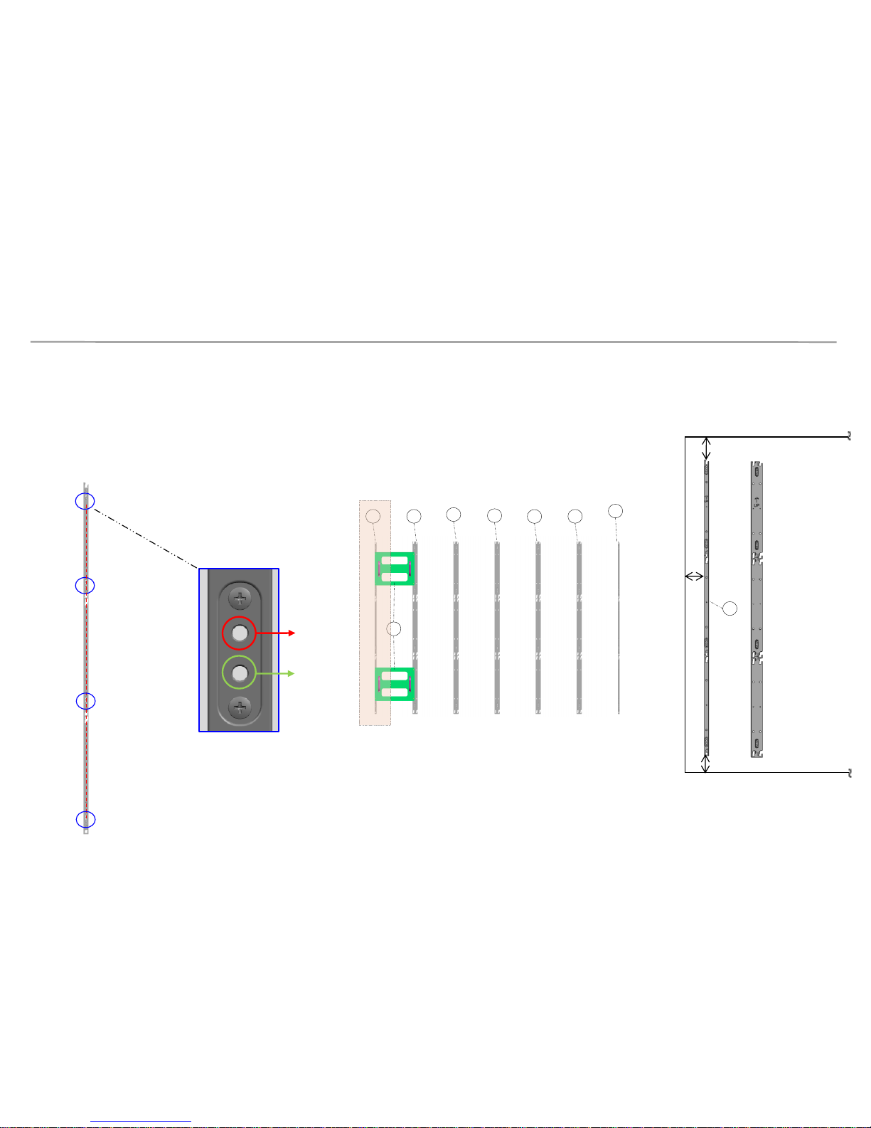
① Put the ⓐBracket Side the end of the left side and then fasten the screws to install. (Fig.3)
※ After fastening one(1) screw, use the device for vertical positioning to set up straight vertical alignment. Then fasten up the remaining
holes. (Refer to Page 11 for the Precautions for fixing the Screws)
Order of Fastening the Screws (No. 1 → No. 2 → No. 3 → No. 4). (Fig.1)
ⓐ Bracket Side is located at 7mm of the end line of the screen. (Fig.4)
Fastened
Hole
Reserved
hole
No. 1
Fig.1 (Order of Work)
No. 2
No. 3
No. 4
Fig.2(Reserved Holes)
a
a
b
b
b
b
b
c
Fig.3 (Location of Components)
10
Fig.4 (Distance between
Screen and Bracket side)
Min. 12mm
Min. 25mm
Min. 12mm
a
Samsung Electronics
3. Frame Installation
※ Precautions for Fastening the Screws
11
Samsung Electronics
3. Frame Installation
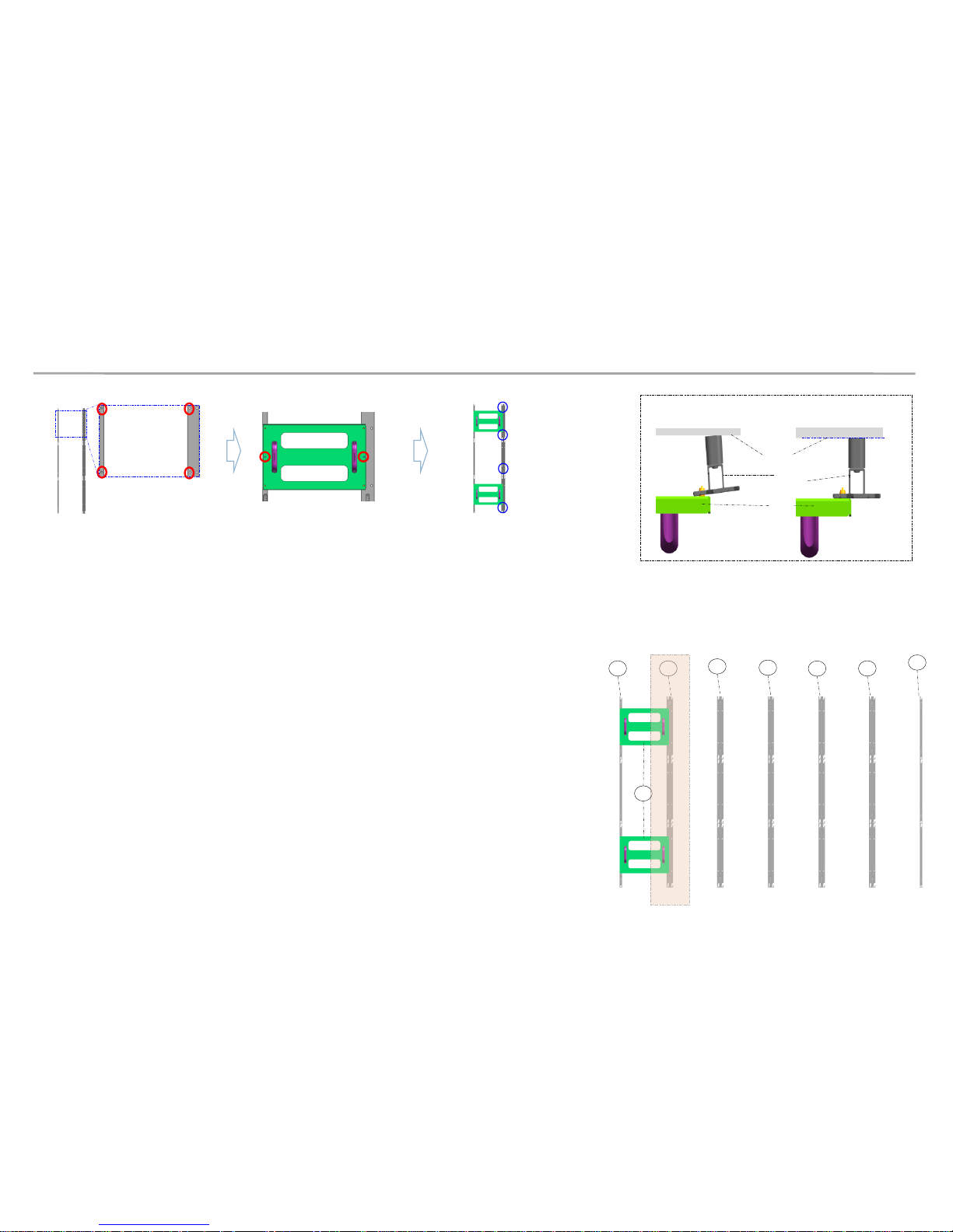
② Install ⓑBracket Center.
※ First, check the Hole to fix the ⓒ JIG. [Fig.1]
※ Second, Mount the ⓒ JIG inside the Bracket Hole and fasten up two(2) Screws [Fig.2]
※ Third, fasten the ⓑ Bracket Center using Screws. [Fig.3]
※ Warning. ⓐ,ⓑand ⓒ sides should be attached,
and the three(3) sides of Wall/Frame side/Jig side should be parallel.[Fig.4]
③ Install in the same way (from left to right)
※ The farthermost right side (the last side) should be installed
using ⓐBracket Side.
Fig1. Check the Hole
Fig2. Fix the Jig (Screw)
Fig4. Maintain the Parallel Frame
Fig3. Fasten the Screw
ⓐ,
ⓑ
Wall
Wrong Installation (X) Correct Installation (O)
ⓒ
a
a
b
b
b
b
b
c
Fig.5 (Location of Components )
12
 Loading...