How it Works
Log In / Sign Up
Buy Points
How it Works
FAQ
Contact Us
Questions and Suggestions
Users
Samsung
Loading...
S
SA19A100N
SA300
SA3ARA04
SA3ARA08
SA3ARA16
SA3ARA32
SA501TB
SA501TP
SA501TW
SA600CB
SA600CP
SA600CW
SA604C series
SA850
2
SAB-100
SA-C600W
SADPCI-202
sadt-100cm
3
SADT-100EC
4
SADT-100HM
3
sadt-100pm
3
SADT-100WM
3
SADT - 101EC
3
SADT-101WM
4
SADT-102WM
SADT-103WM
3
SADT-104WM
3
Sadt-110
Sadt-110cm
2
Safety information
SafeVIEW SEW-3037W
2
Saga
Saga SCH-I770
SagaTM-BJ18-PM-102208-F6
SAH-M1703
SAH-M1703T
SAH-M2303
SAH-M2303S
SAH-M3003
SAH-M4003
SAH-M4003T
SAH-M8004
SAH-M8007
SAH-M8007S
SAM-14MV
SAM-150
SAM 18650 30Q
3
SAM 18650 35E S
2
SAM-2000i
SAM-21M
SAM25405C/XAA
SAM27405C/XAA
SAM335
SAM335A
SAM4S ECR SPS-1000
Sam4s SER-6500II Series
Sam4s SER-6540II Series
SAM52
SAM52M
SAM911
SAMBLK2200
SAMBLK2200 Overview
SAM CRM 12
SAM CRM 13
SAM CRM 13A
SAM CRM 14
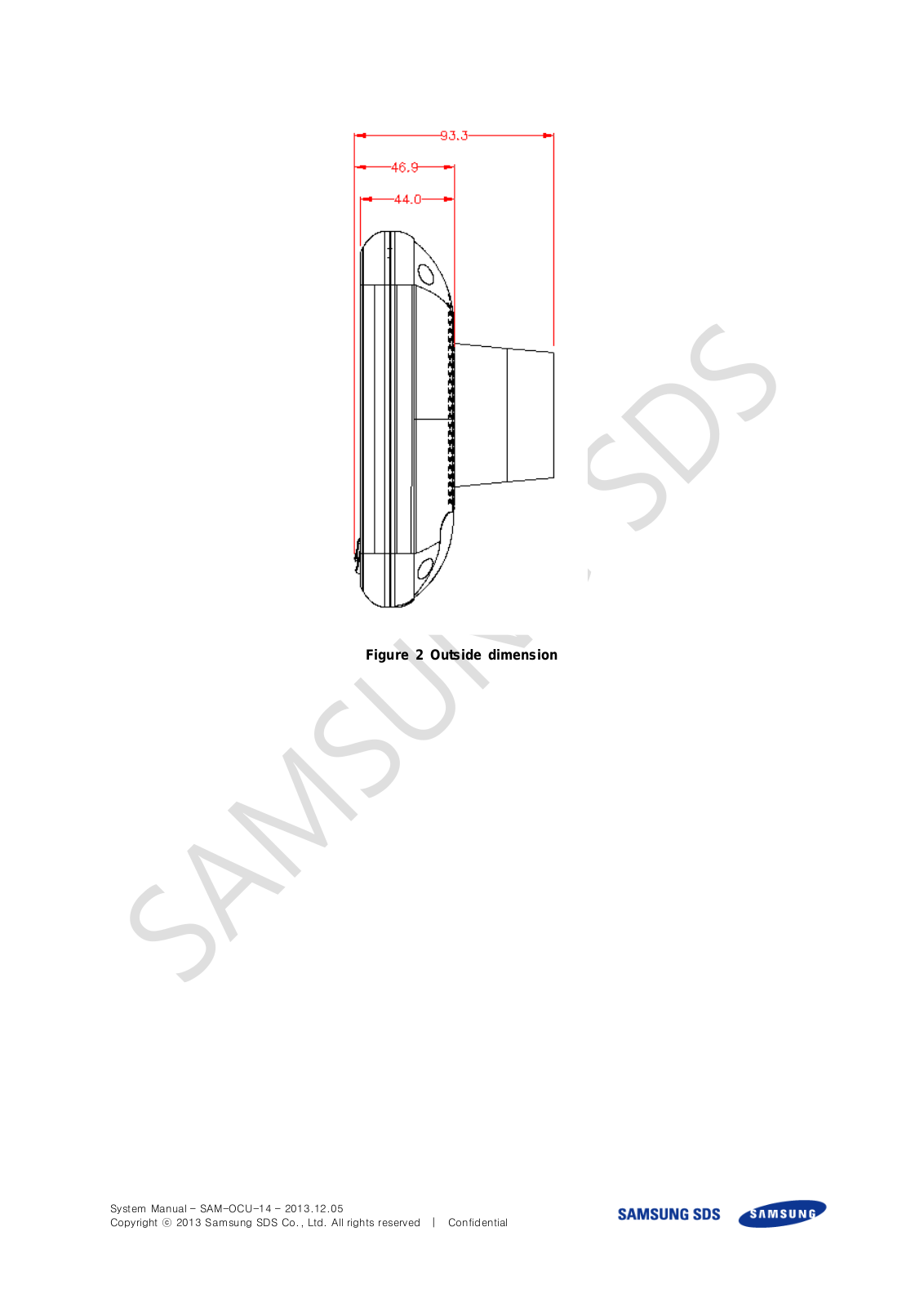
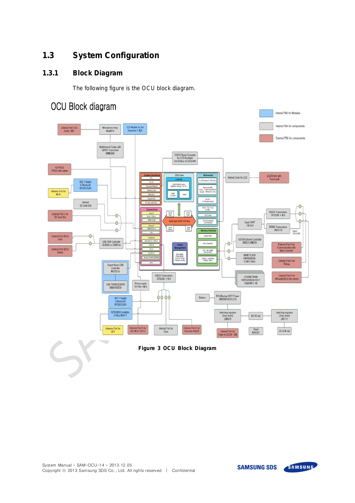
SAM OCU 14
SAMS5012
SAMS MB-MC256KA
SAMSUBG P1000
Samsung 18-55mm
Samsung 60"" Class Q60B Q4K
3
Samsung ATIV Smart PC Pro
SAMSUNG_BL103
SAMSUNG_CL65
SAMSUNG CTC43PRO(SP431JMFX), CTC52PRO(SP521JMFX), SP431FES, SP431JMFX, SP434, SP434JMFX, SP434JMFX/SAP, SP434JMTRX, SP434SAP, SP434VST, SP434VWT, SP434XSA, SP521JMFX, SP521XSA, SP524, SP524AWF, SP524JMFX, SP524JMFX/MUR, SP524JMTRX, SP524SIG, SP524VST, SP53J5MF3XTL
SAMSUNG D760
SAMSUNG D860
Samsung D Series
SAMSUNG ES29
SAMSUNG_HZ15W
SAMSUNG_HZ25W
SAMSUNG L600
SAMSUNG L735
SAMSUNG P83
SAMSUNG PL20
Samsung Q67A Q4K Smart (2021)
Samsung Q95T
2
SAMSUNG_SL201
SAMSUNG_SL310W
SAMSUNG_SL420
SAMSUNG_SL502
Samsung soundcamp
SAMSUNG SP403JHAX TELEFUNKEN RW734E THOMSON 40RW34E
SAMSUNG ST560
Samsung-T Protocol
Samsung TV
4
SAMSUNG WB510
SAMSUNG WB560
SAMSUNG СТРОКА aaa
Loading...
Loading...
Nothing found
SAM OCU 14
User Manual
22 pgs
1.38 Mb
0
Table of contents
Loading...
Samsung SAM OCU 14 User Manual
...
Samsung User Manual
Download
Specifications and Main Features
Frequently Asked Questions
User Manual
Download
Loading...
+
hidden pages
Unhide
You need points to download manuals.
1 point = 1 manual.
You can buy points or you can get point for every manual you upload.
Buy points
Upload your manuals
 Loading...