

Page 1
Page 2
WARNING
TO REDUCE THE RISK OF FIRE OR ELECTRIC SHOCK, DO NOT EXPOSE THIS
MONITOR TO RAIN OR MOISTURE.DO NOT INSERT ANY METALLIC OBJECT
THROUGH VENTILATION GRILLS.
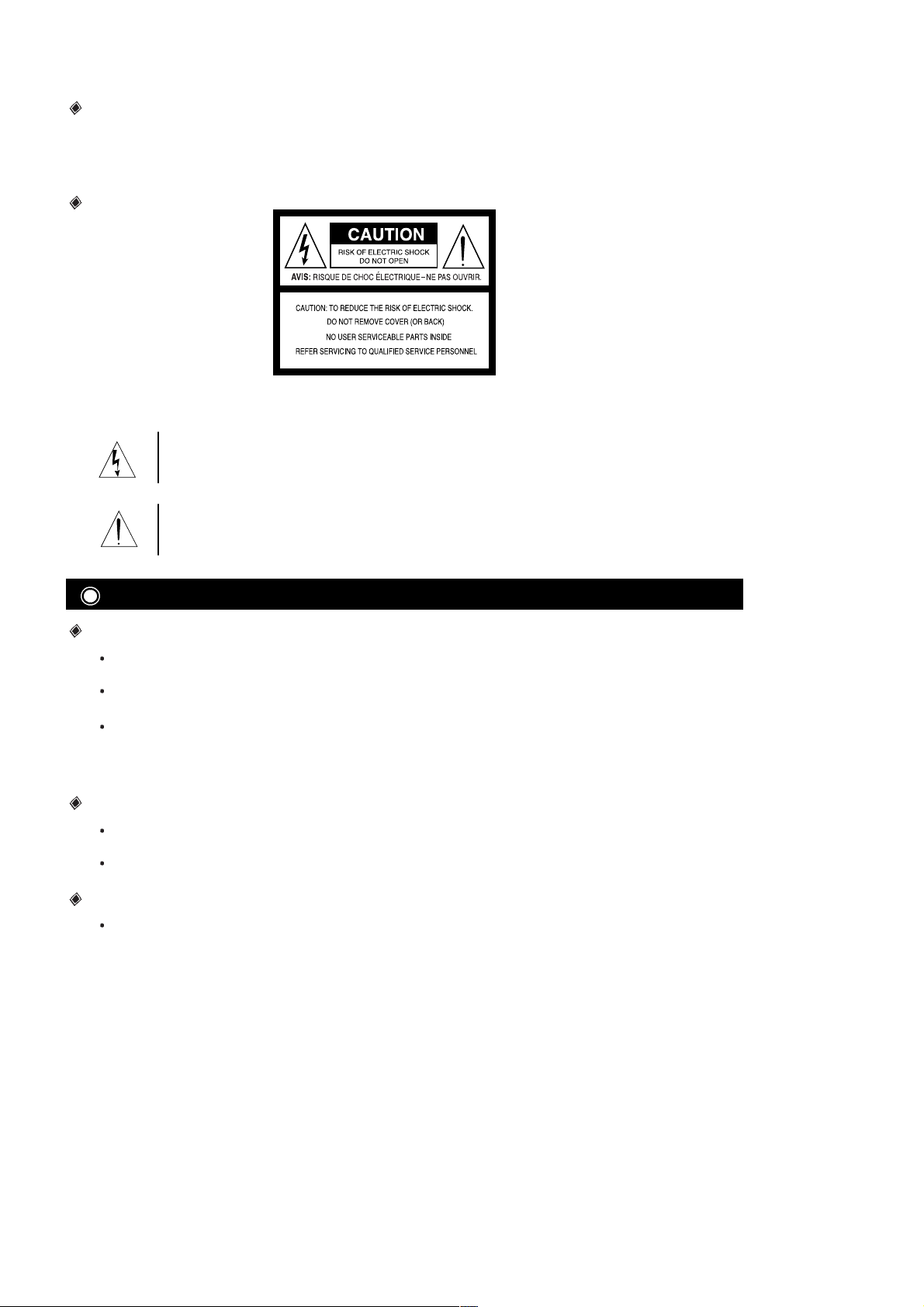
CAUTION
Explanation of Graphical Symbols.
This lightning flash with arrowhead symbol within an equilateral triangle is intended to alert the
user to the presence of uninsulated dangerous voltages within the product’s enclosure that
may be of sufficient magnitude to constitute a risk of electric shock to persons.
The exclamation point within an equilateral triangle is intended to alert the user to the
presence of important operating and maintenance (Servicing) instructions in the
literature accompanying the appliance.
Safety
Should any liquid or solid object fall into the cabinet, unplug the unit and have it checked by
qualified personnel before operating it any further.
Unplug the unit from the wall outlet if it is not going to be used for several days or more. To
disconnect the cord, pull it out by the plug. Never pull the cord itself.
Allow adequate air circulation to prevent internal heat buildup. Do not place the unit on
surfaces (rugs, blankets, etc.) or near materials (curtains, draperies) that may block the
ventilation holes.
Installation
Do not install the unit in an extremely hot or humid place or in a place subject to excessive
dust or mechanical vibration.
The unit is not designed to be waterproof. Exposure to rain or water may damage the unit.
Cleaning
Clean the unit with a slightly dampened soft cloth. Use a mild household detergent.
Never use strong solvents such as thinner or benzene as they might damage the surface of the
unit.
2
PRECAUTIONS
Page 3
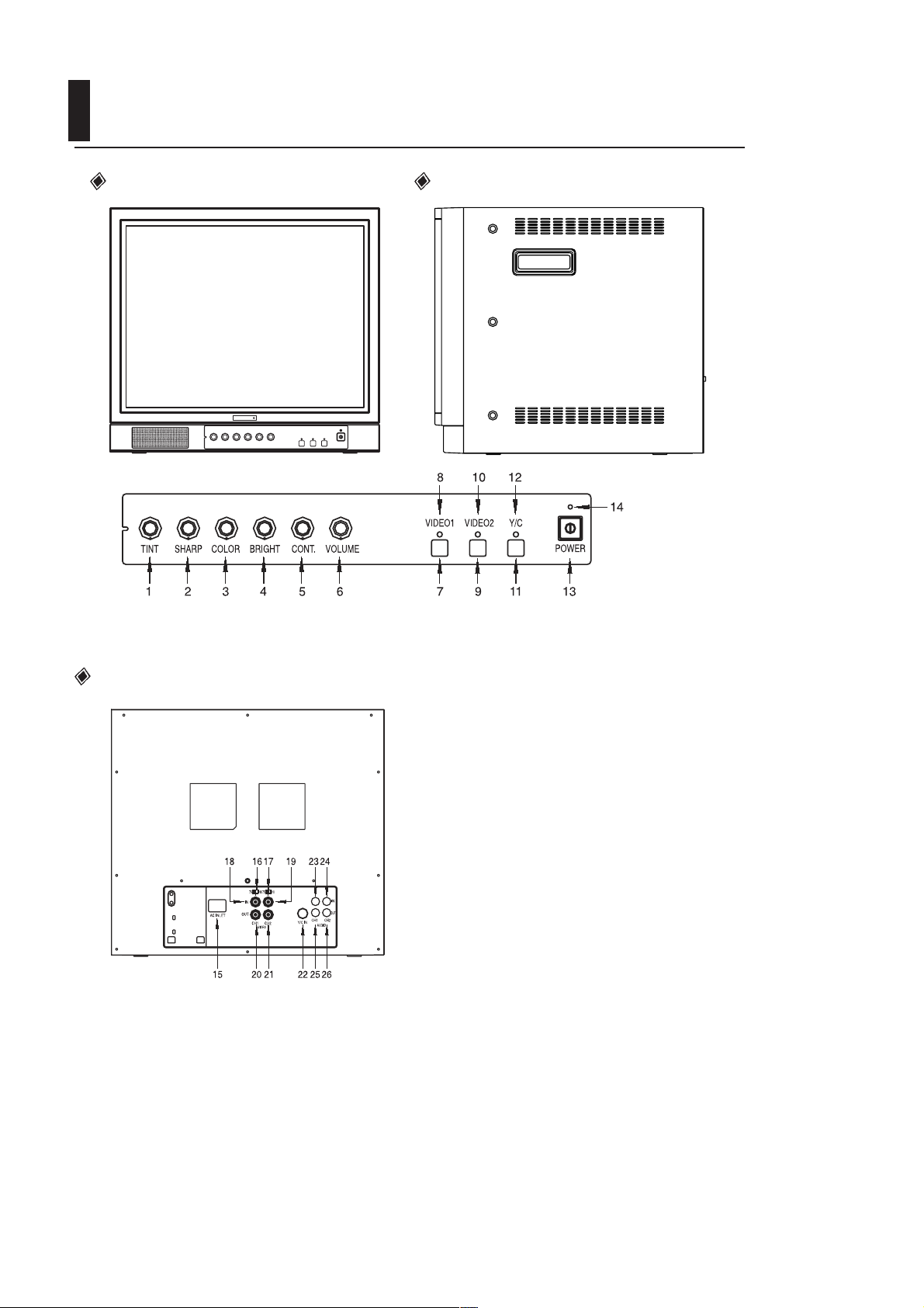
LOCATION CONTROLS
Front View Side View
Rear View
1. TINT
2. SHARPNESS
3. COLOR
4. BRIGHTNESS
5. CONTRAST
6. VOLUME
7. VIDEO 1
8. VIDEO 1 LED LAMP
9. VIDEO 2
10. VIDEO 2 LED LAMP
11. Y/C
12. Y/C LED LAMP
13. POWER BUTTON
14. POWER LED LAMP
15. POWER INLET
16. IMPEDANCE (SLIDE S/W)
17. IMPEDANCE (SLIDE S/W)
18. CHANNEL 1 IN(BNC)
19. CHANNEL 2 IN(BNC)
20. CHANNEL 1 OUT(BNC)
21. CHANNEL 2 OUT(BNC)
22. Y/C IN(DIN)
23. CHANNEL 1 AUDIO IN(RCA)
24. CHANNEL 2 AUDIO IN(RCA)
25. CHANNEL 1 AUDIO OUT(RCA)
26. CHANNEL 2 AUDIO OUT(RCA)
3
Page 4

1. TINT
Adjust the TINT control for the proper color phase or flesh tones. When turned counterclockwise,
the skin tone becomes reddish. When turned clockwise, skin tone becomes greenish.
2. SHARPNESS
Adjust the SHARPNESS control to obtain the clearest picture.
3. COLOR
Adjust the COLOR control to set the color saturation level. Turn the control clockwise to increase
and counterclockwise to decrease.
4. BRIGHTNESS
Adjust the BRIGHTNESS control for the desired overall display brightness. This control is also
useful to compensate for differences in area lighting. Turn the control clockwise to increase and
counterclockwise to decrease.
5. CONTRAST
Adjust the CONTRAST control for the desired overall contrast. Proper adjustment will allow
maximum gradations between the darkest and lightest picture areas. Turn the control clockwise to
increase and counterclockwise to decrease.
6. VOLUME
Adjust the VOLUME control for the desired audio level. Turn the control clockwise to increase and
counterclockwise to decrease.
7. VIDEO 1 TACT SWITCH
Set the switch to VIDEO 1 if the camera jack is used.
8,10,12. VIDEO LED LAMP
VIDEO lamps indicater video mode in selected.
9. VIDEO 2 TACT SWITCH
Set the switch to VIDEO 2 if the camera jack is used.
11. Y/C TACT SWITCH
Set the switch to S-VHS if the S-VHS jack is used.
13. POWER SWITCH
Press to turn the monitor ON. The POWER LAMP above the switch will illuminate.
14. POWER LED LAMP
Power lamp indicates the power is on.
15. POWER INLET
Use 100-240V AC, 50/60 Hz.
To prevent electrical shocks and fire hazards, do not use any other power source.
16,17. IMPEDANCE SWITCH
Set the switch to the HIGH position if the VIDEO OUTPUT jack is used.
The last monitor should be set in the 75
position.
Set the switch to the 75
position if the VIDEO OUTPUT is not used.
18 21. VIDEO INPUT & OUTPUT CONNECTORS
These BNC connectors permit looping of a video signal in those installations where it is desirable
to display the video signal on more than one monitor. A standard 1.0 Vp-p video signal applied to
the VIDEO INPUT will also appear at the VIDEO OUTPUT. Use coaxial cables with BNC type
plugs for these connections.
22. S-VHS JACK
If your input is S-VHS (VIDEO), connect directly to this jack.
23 26. AUDIO INPUT & OUTPUT CONNECTORS
Connect an RCA cable between these jacks and the audio output jack of a camera or VCR.
4
LOCATION AND OPERATION OF CONTROLS
Page 5

Video camera
VCR
Video Monitor
Audio
Audio signal cable
Video
Audio
Video
Video signal cable
Video camera
VCR
Video Monitor
Audio
Audio signal cable
Video
Audio
Video
Video signal cable
Video camera
VCR
Video Monitor
Audio
Audio signal cable
Y/C (S-VHS)
S-VHS Signal cable
Audio
Y/C connection (Select input Y/C button)
Read the installation/operation manual thoroughly before connecting equipment.
Turn off the power source before connecting the monitor and external equipment.
VIDEO 1 Connection (Select input VIDEO 1 button)
VIDEO 2 Connection (Select input VIDEO 2 button)
POSSIBLE CONNECTIONS
5
Page 6

IMPORTANT SAFEGUARDS
All the safety and operating instructions should be read before the monitor is operated. Retain the
instructions for future reference.
1. HEED WARNINGS
All warnings on the monitor and in the operating instructions should be adhered to.
2. FOLLOW INSTRUCTIONS
All operating instructions should be followed.
3. CLEANING
Unplug the monitor from the wall outlet before cleaning.
Do not use liquid or aerosol cleaners. Use a cloth slightly dampened with mild household
detergent only.
4. WATER AND MOISTURE
Do not use this monitor near water, for example, near a bathtub, wash bowl, kitchen sink,
swimming pool, laundry tub, or in a wet basement.
5. ACCESSORIES
Do not place this monitor on an unstable cart, stand, tripod, bracket, or table. Do not drop.
6. VENTILATION
Slots and openings in the cabinet are provided for ventilation.
To ensure reliable operation of this monitor and to protect it from overheating, the openings must
not be blocked or covered.
This monitor should never be placed near or over a radiator or heat register or in a built-in
installation, such as a bookcase or rack, unless proper ventilation is provided.
7. POWER SOURCES
This monitor should be operated only from the power source indicated on the product label.
8. POWER CORD PROTECTION
Power supply cords should be routed so that they are not likely to be walked on or pinched by
items placed on or against them. Pay particular attention to cords and plugs, convenience
receptacles, and the point where they exit from the unit.
9. This equipment is provided with a three-wire grounding type plug having a third (grounding) pin.
This plug will only fit into a grounding type power outlet. This is a safety feature. If you are unable
to insert the plug into the outlet, contact your electrician to replace your obsolete outlet.
Do not defeat the safety purpose of the grounding type plug.
10. OVERLOADING
Do not overload outlets and extension cords. This can result in a risk of fire or electrical shock.
11. OBJECT AND LIQUID ENTRY
Never push objects of any kind into this monitor through openings, as they may touch dangerous
voltage points or short-out parts that could result in a fire or electrical shock. Never spill liquid of
any kind on the monitor.
12. SERVICING
Do not attempt to service this product yourself, as opening or removing covers may expose you
to dangerous voltage or other hazards. Refer all servicing to qualified service personnel.
6
SAFETY INSTRUCTIONS
Page 7

Picture Tube 21-inch diagonal,90 deflection angle
Power Source 100-240VAC, 50/60 Hz
Power Consumption 67 Watts
System PAL / NTSC
Sound output 1.0 W
Resolution Center resolution : 450 TV lines or more
Speaker 3 W , 70 mm X 40 mm
Terminals Video input level/impedance: 1.0 Vpp/75
Video output level/impedance: 1.0 Vpp/75
S-VHS INPUT
Audio input level/impedance: 0.3 Vrms/25K
Audio output level/impedance: 0.3 Vrms/4.7K
Dimensions(W H D) 18.7 in 16.9 in 18.4 in (476 430 468 mm)
Weight Approx. 57.3 lb (26Kg)
Operating Temperature 0-40 (32-106 F)
Design and specifications are subject to change without notice.
7
SPECIFICATIONS
Warning
This is a Class A product. In a domestic environment this product may cause radio interference in
which case the user may be required to take adequate measures.
Page 8

11955739B
SAMSUNG TECHWIN CO., LTD.
145-3 Sangdaewon 1-Dong, Joongwon-Gu
Sungnam, Kyungki-Do, Korea
462-121
TEL: 82-342-740-8137~8141
FAX: 82-342-740-8145
SAMSUNG OPTO-ELECTRONICS AMERICA, INC.
CLOSED CIRCUIT VIDEO DIV.
40 Seaview Drive, Secaucus N.J. 07094,
U.S.A
TEL: 201-902-0347
FAX: 201-902-9342
SAMSUNG TECHWIN CO., LTD.
FRANKFURT OFFICE.
Samsung Haus, Am Kronberger
Hang 6, 65824, Schwalbach,
TS. Germany
TEL: 49(0)6196-667500 FAX: 49(0)6196-667566
SAMSUNG OPTO-ELETRÔNICA DO BRASIL LTDA.
Rua Professor Manoelito de Ornellas 303•2º andar
Chácara Santo Antoˆnio•CEP : 04719-040
São Paulo•SP•Brasil
TEL: 55-11-5642-0757
FAX: 55-11-5641-8023
 Loading...