

Samsung SADT-100WM, SADT-101WM User Manual
WALL MOUNT ADAPTOR
SADT-100WM
Installation Manual
Installationshandbuch
Manuel D’installation
Manual De Instalación
GB
D
F
E
C
J
K
AB68-00233A
PRINTED IN KOREA
Summary
Installation
The Wall Mounted Adaptor (SADT-100WM) is used for the
installation of the Smartdome Camera (indoor or outdoor housing)
on walls.
Precautions Before Installation
Make sure that the proposed location can support the combined weights of the Wall
•
Mounted Adaptor, Outdoor Housing and Smartdome Camera (about 8 kg).
This product is designed to use M10 anchor bolts or nuts.
•
When installing the product on a concrete wall, use M10 anchor bolts/nuts together
•
with plain and spring washers.
Each anchor bolt must be capable of withstanding an extraction force of 700 kg.
•
When installing the product outdoors, use interlocking devices made of stainless steel.
•
The Wall Mounted Adaptor may be installed directly on a wall or in conjunction with
•
the Corner Mounted Adaptor (SADT-110CM) or the Pole Mounted Adaptor
(SADT-100PM), in which cases a PG-13.5 cable gland should be used.
This goods should only be installed by a qualified technician using approved materials
•
and wiring practices in accordance with national, state, and local electrical code.
Select a location that will support four times the total weight of the
1
product to be installed (about 32 kg).
Use the Back Plate to mark the positions of the M10 anchor
2
bolts/nuts on the wall, drill the holes and install the anchor
bolts/nuts.
• When installing in the corner of a wall, use the Corner Mounted Adaptor
(SADT-110CM). When installing on a pole, use the Pole Mounted Adaptor
(SADT-100PM).
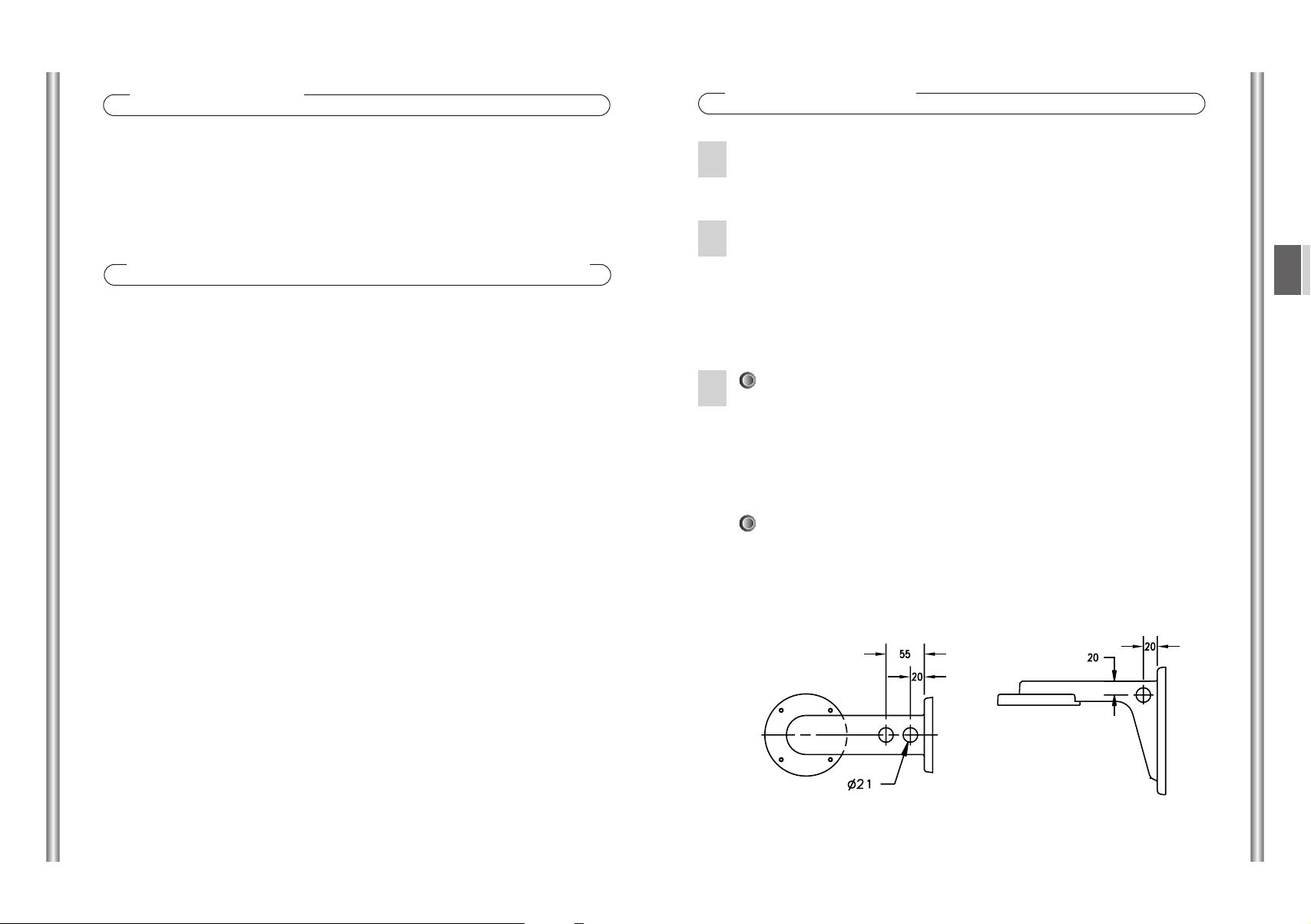
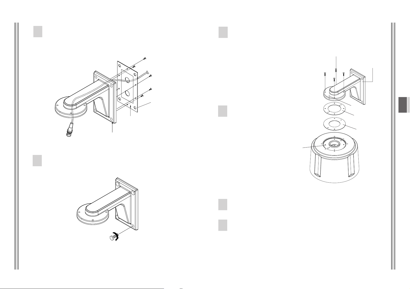
If the cable pipe is installed inside the wall:
3
1) Pull the power cable, video-out cable and communications cable out through
the holes of the Back Plate and Wall Mounted Adaptor. Take care not
toavoid damageto the cable sleeving.
When installing with the Corner Mounted Adaptor or the Pole Mounted
•
Adaptor, use a PG-13.5 Cable Gland for watertightness.
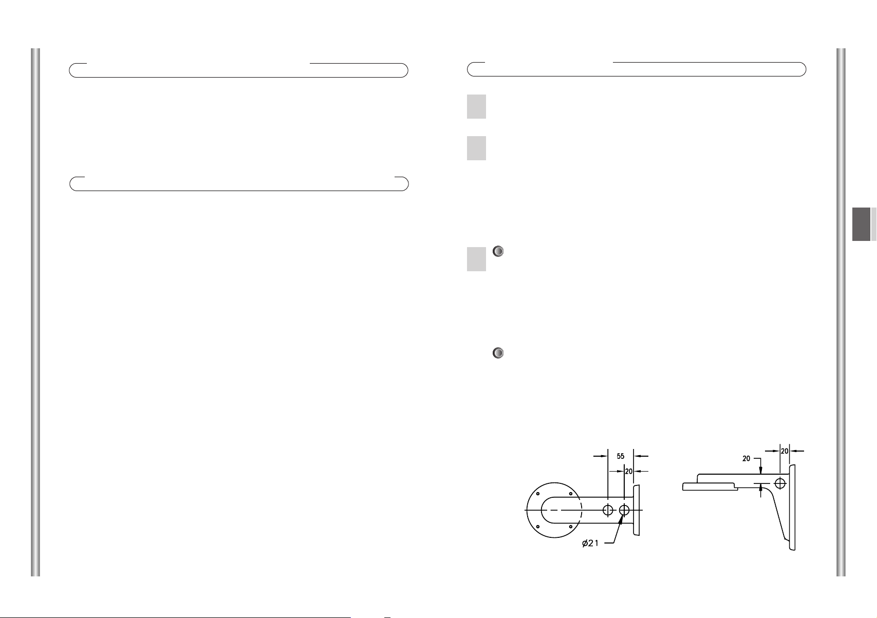
If the cable pipe is installed on the wall:
1) Make a hole of 21mm in diameter on the outside of the pipe (on the side and
near the tip) and install a PG13.5 cable gland.
2) Pull the cables out to the Wall Mounted Adaptor through the cable gland.
Positions for the hole (unit: mm)
•
GB
1
2
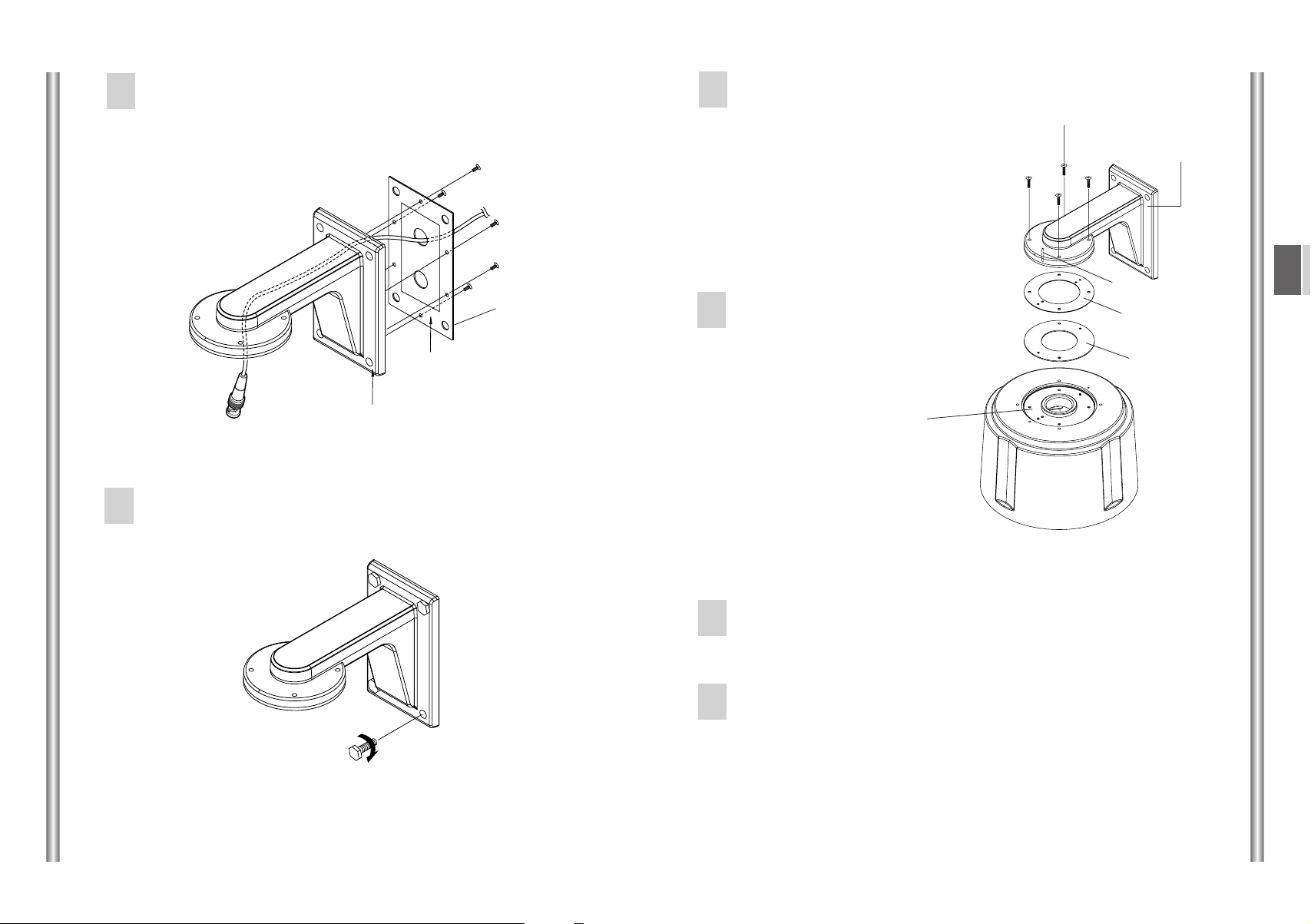
Fix the Back Plate to the Wall Mounted Adaptor using six
4
screws (M3 x L6). (Taking care that the gasket remains in
contact with the Wall Mounted Adaptor.)
Separate the dummy plate from
6
the housing top by removing the
two screws and attach the
waterproofing gasket.
(When attaching the gasket, take
care to align the guiding bosses
correctly with the holes in the
housing.)
Screw (BH M4 X L22)
Wall Mount
Adaptor
Back Plate
Gasket
Wall Mount Adaptor
Securely fasten the Wall Mounted Adaptor to the wall using
5
the anchor bolts/nuts.
Align the Wall Mounted Adaptor
7
bosses with the Housing holes
and assemble the Housing to the
Adaptor using four screws
(BH M4 x L22).
Gasket
attachment
after
separating
Dummy Plate
Install the Housing in accordance with the Housing
8
installation manual.
After installing the adaptor, apply silicon sealant around the
9
adaptor and between the adaptor and the wall for water
tightness.
If the wall surface is uneven, pay particular attention that no
gaps are left.
Boss
GB
Gasket
Dummy Plate
3 4
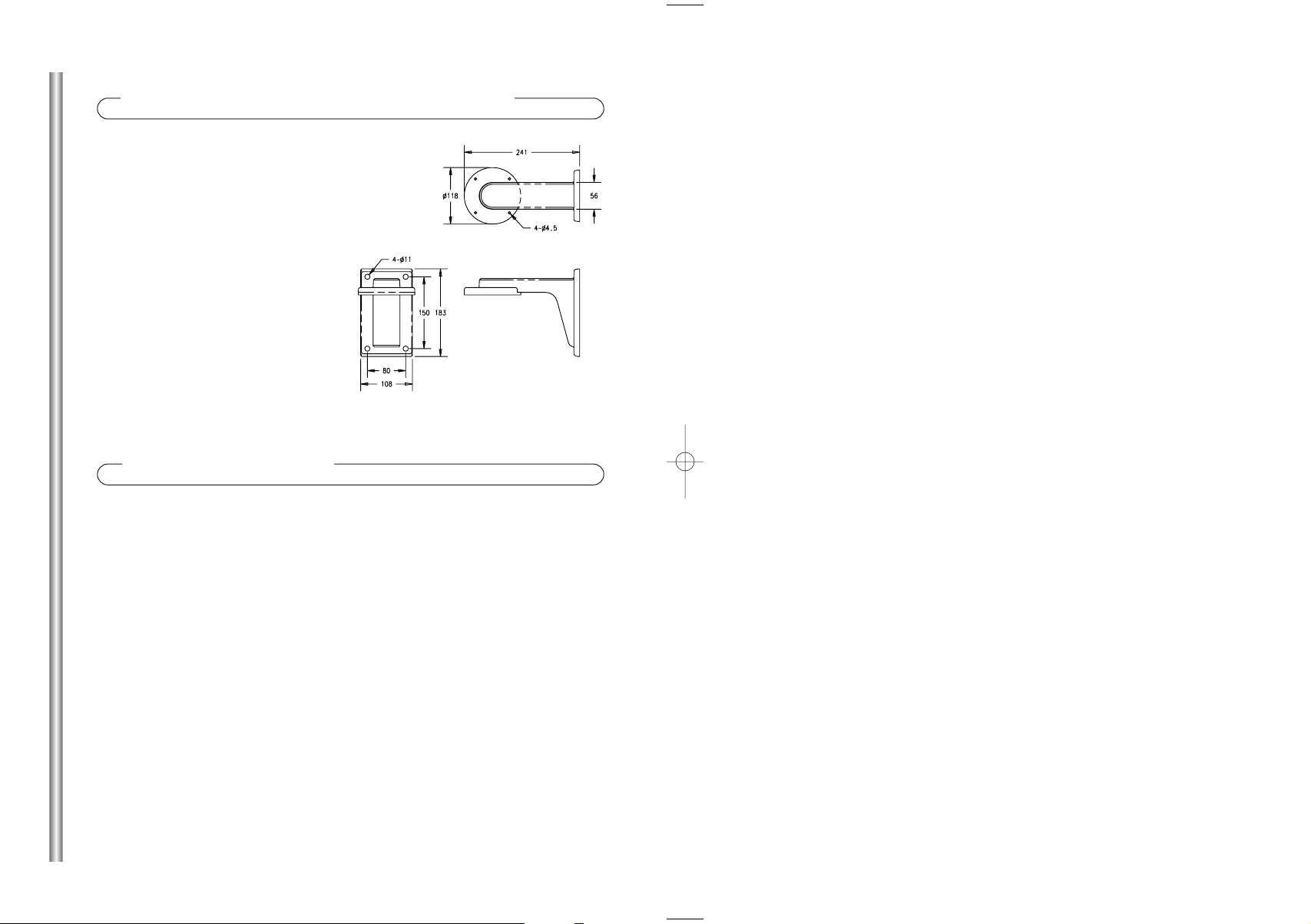
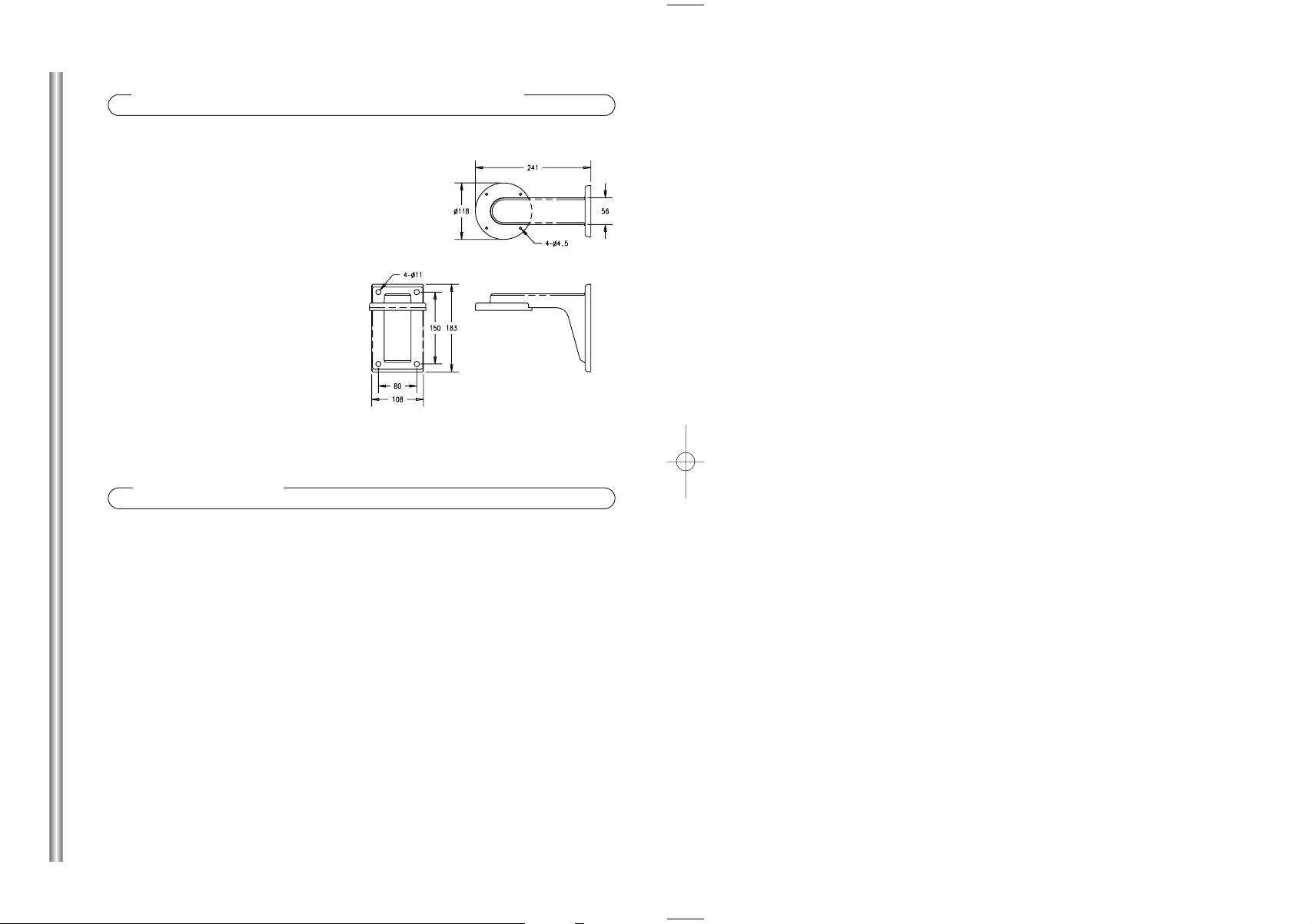
Product Specifications
Location for use: Indoors or outdoors
Location of installation:
Wall or vertical structure
External dimensions: See the diagram
Weight: 800g
Material: Aluminum
Suitable Temperature range:
- 40°~ 50°C
Suitable Humidity range:
0~100%
Accessories
Gasket
Back Plate
Screw (FH M3 X L6)
Screw (BH M4 X L22)
Cable gland (PG-13.5)
5
..................................................
...........................................
...........................
.........................
.......................
1
1
6
4
2
Zusammenfassung
Installation
Der Wandadapter (SADT-100WM) dient zur Installation der
Smartdome Camera (Innenraum- oder Außengehäuse) auf
Wänden.
Vorsichtsmassnahmen Vor Der Installation
Stellen Sie sicher, dass der geplante Ort das Gesamtgewicht von Wandadapter,
•
Außengehäuse and Smartdome Camera (ca. 8 kg) tragen kann.
Das Produkt ist für die Verwendung von M10-Ankerbolzen und -muttern konstruiert.
•
Wenn Sie das Produkt auf einer Betonwand installieren, benutzen Sie die
•
M10-Ankerbolzen/-muttern zusammen mit Unterleg- und Federscheiben.
Jeder Ankerbolzen muss für eine Zugkraft von 700 kg ausgelegt sein.
•
Wenn Sie das Produkt im Freien installieren, benutzen Sie
•
Verriegelungsvorrichtungen aus rostfreiem Stahl.
Der Wandadapter kann direkt auf einer Wand oder in Verbindung mit dem Eckadapter
•
(SADT-110CM) oder dem Pfostenadapter (SADT-100PM) installiert werden, wobei
eine PG-13,5- Kabeleinführung verwendet werden sollte.
Wählen Sie eine Position, die das vierfache Gesamtgewicht (ca. 32
1
kg) des zu installierenden Produktes tragen kann.
Benutzen Sie die Rückplatte, um die Stellen für die M10-
2
Ankerbolzen/-muttern an der Wand zu kennzeichnen. Bohren Sie
die Löcher und installieren Sie die Ankerbolzen/-muttern.
• Wenn die Installation in der Ecke einer Wand vorgenommen werden soll,
verwenden Sie den Eckadapter (SADT-110CM). Wenn die Installation an einem
Pfosten vorgenommen werden soll, verwenden Sie den Pfostenadapter
(SADT-100PM).
Wenn das Kabelrohr in der Wand installiert ist:
3
1) Ziehen Sie Netzanschlusskabel, Videoausgangs-Kabel und
Datenübertragungskabel durch die Löcher der Rückplatte und des
Wandadapters heraus. Achten Sie darauf, dass dabei die
Kabelummantelungen nicht beschädigt werden.
Verwenden Sie bei der Montage des Eckadapters oder des
•
Pfostenadapters eine PG-13.5-Kabeleinführung zur Wasserabdichtung.
Wenn das Kabelrohr auf der Wand installiert ist:
1) Machen Sie Loch von 21mm Durchmesser auf der Außenseite des Rohres
(an der Seite, in Nähe des Rohrendes) und montieren Sie eine PG13.5Kabeleinführung.
2) Ziehen Sie die Kabel durch die Kabeleinführung heraus zum Wandadapter.
Positionen für das Loch (Einheit: mm)
•
D
1
2
Befestigen Sie die Rückplatte mit sechs Schrauben am
4
Wandadapter (M3xL6). (Achten Sie darauf, dass die Dichtung
in Kontakt mit dem Wandadapter bleibt.)
Nehmen Sie die Abdeckplatte vom
Gehäuseoberteil ab, indem Sie die
6
zwei Schrauben entfernen und
befestigen Sie die Dichtung, um
das Gehäuse wasserdicht zu
machen.
(Achten Sie beim Anbringen der
Dichtung darauf, dass die
Führungsnaben richtig zu den
Löchern im Gehäuse ausgerichtet
sind.)
Schraube (BH M4 X L22)
Wandadapter
Rückplatte
Dichtung
Wandadapter
Befestigen Sie den Wandadapter mit Ankerbolzen/-muttern an
5
der Wand.
Richten Sie die Naben des
7
Wandadapters zu den
Gehäuselöchern aus und
montieren Sie das Gehäuse mit
vier Schrauben (BH M4 x L22) an
den Adapter.
Befestigung der
Dichtung nach
Entfernen der
Abdeckplatte
Installieren Sie das Gehäuse wie im Installationshandbuch
8
des Gehäuses beschrieben.
Nachdem Sie den Adapter installiert haben, tragen Sie zur
9
Wasserabdichtung die Silikondichtungsmasse um den
Adapter und zwischen Adapter und Wand auf.
Wenn die Wandoberfläche uneben ist, achten Sie
besonders darauf, dass keine Lücken entstehen.
Nabe
Dichtung
Abdeckplatte
D
3 4
Produktspezifikationen
Verwendungsort: Innenräume oder im Freien
Ort der Installation: Wand oder
eine vertikale Struktur
Äußere Abmessungen:
Siehe Diagramm
Gewicht: 800 g
Material: Aluminium
Geeigneter Temperaturbereich:
- 40°~ 50°C
Geeigneter Luftfeuchtigkeitsbereich:
0 ~100%
Zubehör
Dichtung
Rückplatte
Schraube (FH M3 x L6)
Schraube (BH M4 x L22)
Kabeleinführung (PG-13,5)
5
..............................................
...........................................
......................
...................
..............
1
1
6
4
2
 Loading...