

Page 1

Alignment and Adjustments
Samsung Electronics 4-1
4. Alignment and Adjustments
4-1 General Alignment Instructions
1. Usually, a color TV-VCR needs only slight
touch-up adjustment upon installation. Check
the basic characteristics such as height,
horizontal and vertical sync and focus.
2. Observe the picture for good black and white
details. There should be objectionable color
shading; if color shading is present,
demagnetize, perform purity and convergence
adjustments described below.
3. Use the specified test equipment or its
equivalent.
4. Correct impedance matching is essential.
5. Avoid overload. Excessive signal from a
sweep generator might overload the front-end
of the TV. When inserting signal markers, do
not allow the marker generator to distort test
results.
6. Connect the TV only to an AC power source
with voltage and frequency as specified on the
backcover nameplate.
7. Do not attempt to connect or disconnect any
wires while the TV is turned on. Make sure
that the power cord is disconnected before
replacing any parts.
8. To protect against shock hazard, use an
isolation transformer.
4-2 Automatic Degaussing
A degaussing coil is mounted around the
picture tube, so that external degaussing after
moving the TV should be unnecessary. But
the receiver must be properly degaussed upon
installation.
The degaussing coil operates for about 1
second after the power is switched ON. If the
set is moved or turned in a different direction,
the power should be OFF for at least 10
minutes.
If the chassis or parts of the cabinet become
magnetized, poor color purity will result. If
this happens, use an external degaussing coil.
Slowly move the degaussing coil around the
faceplate of the picture tube and the sides and
front of the receiver. Slowly withdraw the coil
to a distance of about 6 feet before turning
power OFF.
If color shading persists, perform the
following Color purity and Convergence
adjustments.
4-3 High Voltage Check
CAUTION : There is no high voltage adjustment
on this chassis. The B+ power supply should be
+135 volts (with full color- bar input and normal
picture level).
1. Connect a digital voltmeter to the second
anode of the picture tube.
2. Turn on the TV. Set the Brightness and
Contrast controls to minimum (zero beam
current).
3. Adjust the Brightness and contrast controls to
both extremes. Ensure that the high voltage
does not exceed 30 KV under any conditions.
Page 2
Alignment and Adjustments
4-2 Samsung Electronics
4-4 FOCUS Adjustment
1. Iput a black and white signal.
2. Adjust the tuning control for the clearest picture.
3. Adjust the FOCUS control for well defined scanning lines in the center area of the screen.
4-5 Factory Adjustment
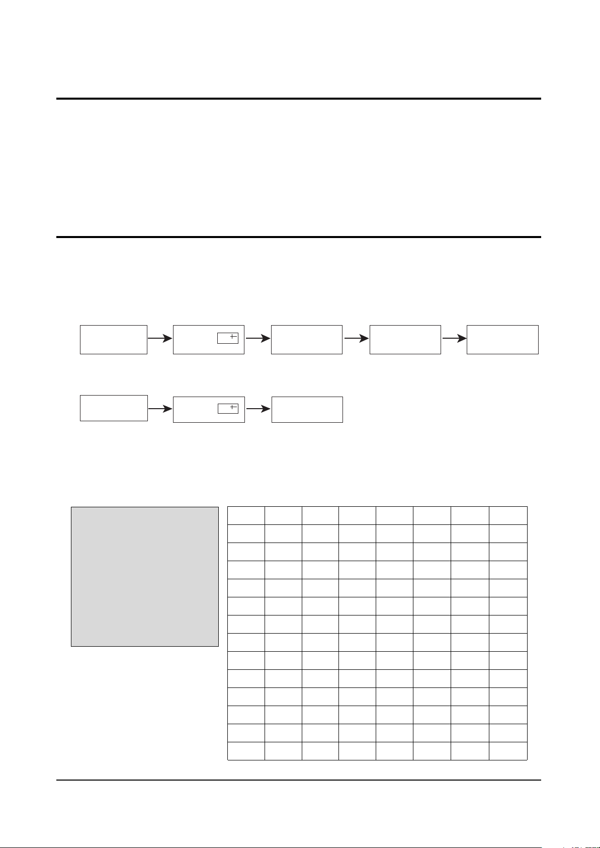
1. To enter the “Service Mode”, Press the remote-control keys in this sequence :
- If you do not have Factory remote-control
- If you have Factory remote-control
4-5-1 Service Mode
4-5-2 Factoy Mode OSD
ADJUST
OPTION 52 2A 48
G2-ADJUST
RESET
SPM-836EAN 2002/02/08
AGC
SCT
SBT
BLR
BLB
RG
GG
BG
VSL
VS
VA
HS
SC
CDL
33
13
9
31
27
32
25
31
19
38
40
30
24
9
STT
AKB
PDL
NDL
PSR
NSR
VOL
LCO
TXP
MVOL
FMWS
AGCS1
OMD
SCL
7
0
15
10
15
10
10
0
9
10
0
1
26
1
PWL
AGN
PEK
ACL
FCO
SCBT
SSP
PSNS
HPAR
HBOW
EWID
EPAR
EUCN
ELCN
12
1
2
0
0
45
20
1
32
32
32
32
32
32
ETRP
VZ
SVM
VMA
DPSR
DNSR
DSBT
DCDL
DBLR
DBLB
32
58
0
0
15
10
7
9
31
27
4-5-2(A) ADJUST
PICTURE OFF PICTURE ON
PICTURE ON
DISPLAY
DISPLAY
()
()
MENU
FACTORY
MUTE
Page 3
Alignment and Adjustments
Samsung Electronics 4-3
OSD
AGC
SCT
SBT
BLR
BLB
RG
GG
BG
VSL
VS
VA
HS
SC
CDL
STT
AKB
PDL
NDL
PSR
NSR
VOL
LCO
TXP
MVOL
FMWS
AGCS1
OMD
SCL
PWL
AGN
PEK
ACL
FCO
SCBT
SSP
Range
0 ~ 63
0 ~ 23
0 ~ 23
0 ~ 63
0 ~ 63
0 ~ 63
0 ~ 63
0 ~ 63
0 ~ 63
0 ~ 63
0 ~ 63
0 ~ 63
0 ~ 63
0 ~ 15
0 ~ 7
0 ~ 1
0 ~ 15
0 ~ 15
0 ~ 23
0 ~ 23
0 ~ 63
0 ~ 1
0 ~ 15
0 ~ 50
0 ~ 1
0 ~ 3
0 ~ 63
0 ~ 3
0 ~ 15
0 ~ 1
0 ~ 3
0 ~ 1
0 ~ 1
0 ~ 63
0 ~ 23
Register
1Eh(D5-D0)
1Dh
1Bh
14h(D5-D0)
15h(D5-D0)
16h(D5-D0)
17h(D5-D0)
18h(D5-D0)
0Fh(D5-D0)
12h(D5-D0)
10h(D5-D0)
09h(D5-D0)
0Fh(D5-D0)
2Ah(D3-D0)
08h
2Ah(D4)
1Ah(D3-D0)
1Ah(D3-D0)
1Ch
1Ch
1Fh
27h(D7-D5)
87F2h(D5-D0)
Oh(D15-D0)
29h(D5)
28h(D2-D1)
05h(D5-D0)
04h(D5-D4)
04h(D3-D0)
29h(D7)
19h(D7-D6)
20h(D1)
21h(D0)
1Bh
19h(D5-D0)
Initial Value
33
13
9
31
27
32
25
31
19
38
40
30
24
9
7
0
15
10
15
10
10
0
9
10
0
1
26
1
12
1
2
0
0
45
20
Remark
RF AGC
Sub contrast(high light adjustment)
Sub brightness(low light adjustment)
Black level offset R(low light R adjustment)
Black level offset B(low light B adjustment)
White point R(high light R adjustment)
White point G(high light 25 fixed)
White point B(high light B adjustment)
Vertical slope
Vertical shift
Vertical amplitude
Horizontal shift
S-correction
Cathode drive level
Sub tint(NTSC only)
Black current stabilization
PAL Y-delay adjustment
NTSC Y-delay adjustment
PAL sub color gain adjustment
NTSC sub color gain adjustment
Initial vol adjustment
PLL demodulator frequency adjust( 0 : set )
TTX horizontal shift adjustment(Micom Memory Part)
Melody initial vol adjustment(MSP34XX)
Narrow-band sound PLL window selection
IF AGC speed
Off-set IF demodulator
Soft clipping level
Peak white limiting
FM demodulator gain
Peaking center frequency
Automatic color limiting
Forced color limiting
Screen brightness(different from INCH)
Sub Sharpness gain adjustment
Page 4
Alignment and Adjustments
4-4 Samsung Electronics
OSD
PSNS
HPAR
HBOW
EWID
EPAR
EUCN
ELCN
ETRP
VZ
SVM
VMA
DPSR
DNSR
DSBT
DCDL
DBLR
DBLB
Range
0 ~ 1
0 ~ 63
0 ~ 63
0 ~ 63
0 ~ 63
0 ~ 63
0 ~ 63
0 ~ 63
0 ~ 63
0 ~ 3
0 ~ 3
0 ~ 23
0 ~ 23
0 ~ 23
0 ~ 15
0 ~ 63
0 ~ 63
Register
21h(D2)
06h(D5-D0)
07(D5-D0)
0Ah(D5-D0)
0Bh(D5-D0)
0Ch(D5-D0)
0Dh(D5-D0)
0Eh(D5-D0)
13h(D5-D0)
2Dh(D5-D0)
2Eh(D5-D0)
1Ch
1Ch
1Bh
2Ah(D3-D5)
14h(D5-D0)
15h(D15-D0)
Initial Value
1
32
32
32
32
32
32
32
32
0
0
15
10
7
9
31
27
Remark
Ident sensitivity PAL/NTSC decoder
Horizontal parallelogram
Horizontal bow
EW width
EW parabola
EW upper corner parabola
EW lower corner parabola
EW tarpezium
Vertical zoom
Delay of RGB output to VM output
Ampulitude of SVM out
DVD PAL sub color gain adjustment
DVD NTSC sub color gain adjustment
DVD Sub brightness(low light adjustment)
DVD Cathode drive level
DVD Black level offset R(low light R adjustment)
DVD Black level offset B(low light B adjustment)
Page 5
Alignment and Adjustments
Samsung Electronics 4-5
ADJUST
OPTION 52 2A 48
G2-ADJUST
RESET
SPM-836EAN 2002/02/08
Item
LNA
SYSTEM
AUDIO
JACK
ZOOM
AUTO POWER
EW
2nd SIF
HOTEL MODE
BKS
HIGH DEVIA
HELP MENU
LANGUAGE
V-GUARD
No
1
2
3
4
5
6
7
8
9
10
11
12
13
14
Initial value
OFF
CS
MONO
RCA
NOR/ZOOM/16:9
ON
ON
ON
OFF
ON
OFF
ON
EAST ASIA
OFF
Remark
CIS : ON
CS - CB -CD
MONO - MONO/BILI - L-STEREO -
L-STEREO/BILI - STEREO - NICAM
RCA - SCART - RCA+DVD
NOR/ZOOM/16:9 - NOR/ZOOM
ON(MUST OFF)
ON - OFF(21”F PIN FREE CRT OFF)
ON - OFF(QUEST OFF)
OFF - ON(OPTION)
ON - OFF(EUROPE OFF)
OFF(MUST OFF)
ON - OFF(EUROPE OFF)
EAST ASIA - CHINA
OFF(MUST OFF)
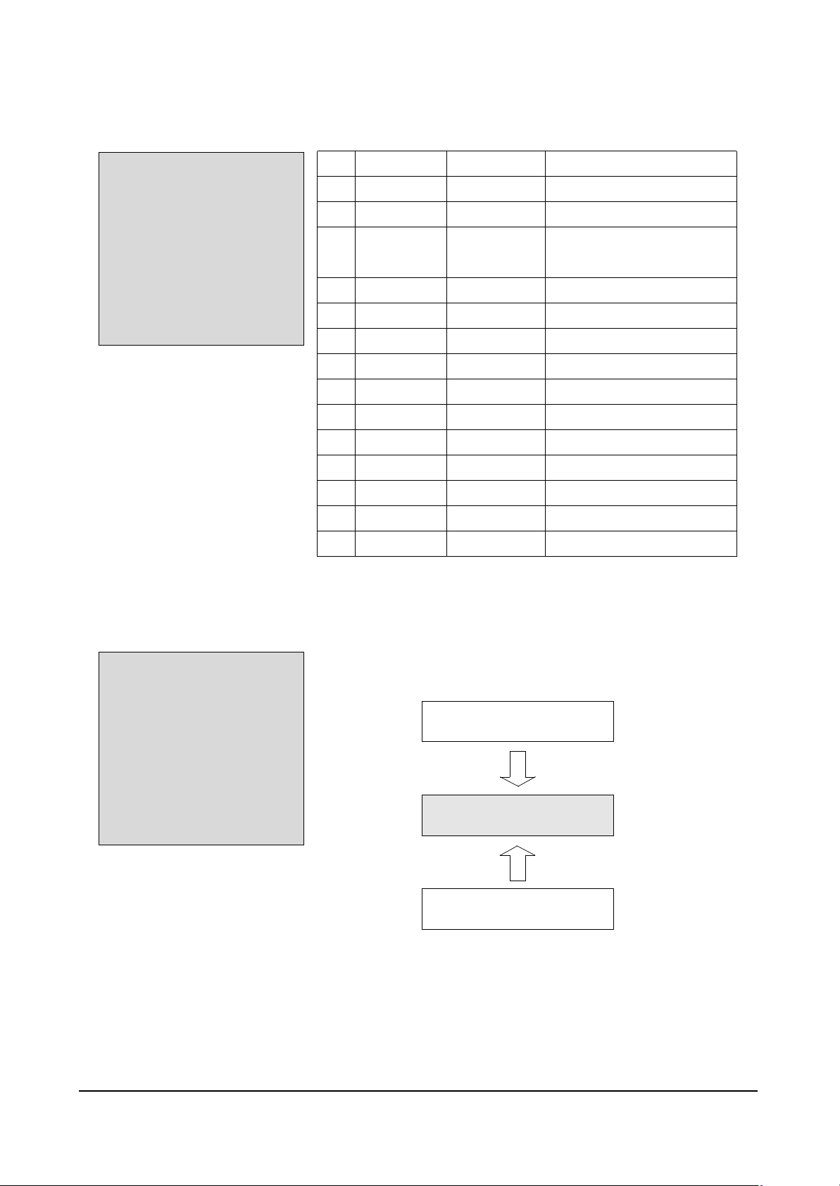
4-5-2(B) OPTION
ADJUST
OPTION 52 2A 48
G2-ADJUST
RESET
SPM-836EAN 2002/02/08
4-5-2(C) G2-ADJUST
☞ Entering G2-Adjust Mode Screen Adjust : Displyed As “NG”.
→ Turn SCREEN VR OF FBT, Adjust Value Become To Be “OK”.
Screen Adjust : N.G
Screen Adjust : O.K
Screen Adjust : N.G
Page 6
Alignment and Adjustments
4-6 Samsung Electronics
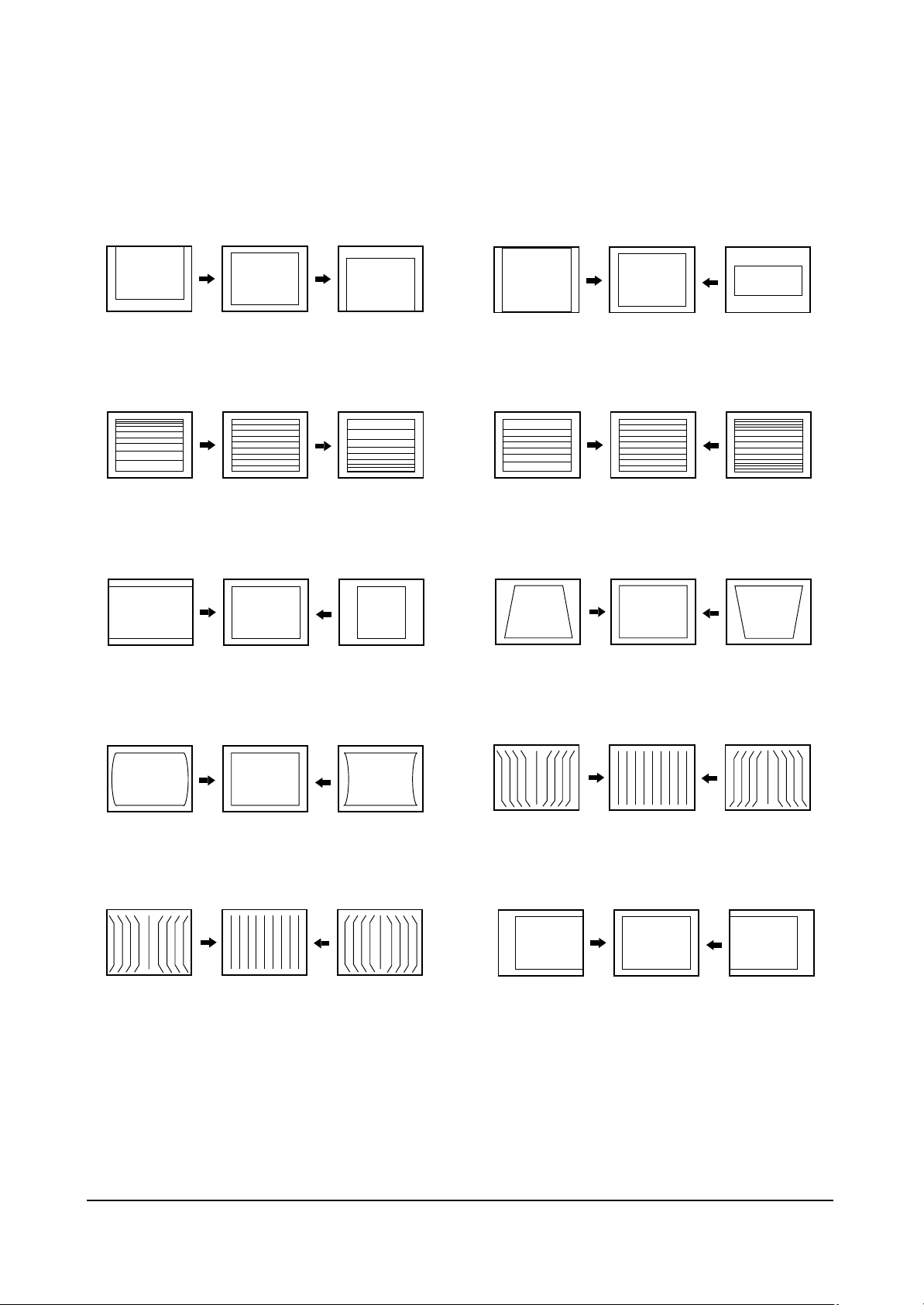
4-5-2(D) SCREEN CHANGE (I2C BUS GEOMETRIC ADJUSTMENT)
1 V Shift
V Slope
2
3 H EW
6 V Amp
V SC
7
8
H Trapizium
4 H Parabola
5 H Corner
9
10
H Shift
H Symmetry
Page 7
Alignment and Adjustments
Samsung Electronics 4-7
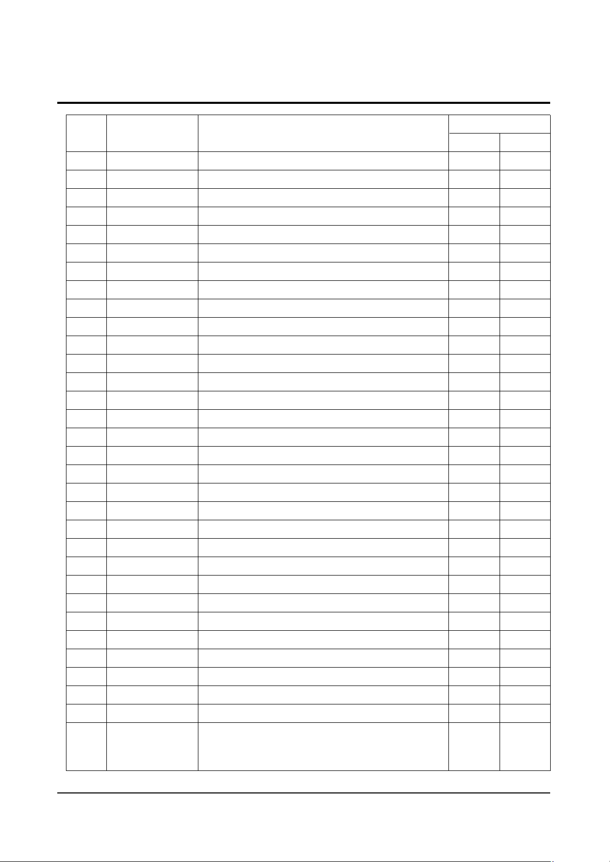
PIN NO
1
2
3
4
5
6
7
8
9
10
11
12
13
14
15
16
17
18
19
20
21
22
23
24
25
26
27
28
29
30
31
32
SYMBOL
P1.3/T1
P1.6/SCL
P1.7/SDA
P2.0/TPMW
P3.0/ADC0
P3.1/ADC1
P3.2/ADC2
P3.3/ADC3
VSSC/P
P0.5
P0.6
VSSA
SECPLL
VP2
DECDIG
PH2LF
PH1LF
GND3
DECBG
EWD
VDRB
VDRA
IFIN1
IFIN2
IREF
VSC
AGCOUT
SIFIN1/DVBIN1
SIFIN2/DVBIN2
GND2
SIFAGC/DVBAGCR
REFO/AMOUT/REFIN
PIN FUNCTION
port 1.3 or Counter/Timer 1 input
port 1.6 or IIC-bus clock line
port 1.7 or IIC-bus data line
port 2.0 or Tuning PWM output
port 3.0 or ADC0 input
port 3.1 or ADC1 input
port 3.2 or ADC2 input
port 3.3 or ADC3 input
digital ground for m-Controller core and periphery
port 0.5(8mA current sinking capability for direct drive of LEDs)
port 0.6(8mA current sinking capability for direct drive of LEDs)
digital ground of TV-processor
SECAM PLL decoupling
2nd supply voltage TV-processor(+8V)
supply voltage decoupling of digital circuit of TV-processor
phase-2 filter
phase-1 filter
ground 3 for TV-processor
bandgap decoupling
East-West drive output
vertical drive B output
vertical drive A output
IF input 1
IF input 2
reference current input
vertical sawtooth capacitor
tuner AGC output
SIF input 1 / DVB input 1
SIF input 2 / DVB input 2
ground 2 for TV processor
narrow band PLL filter
Automatic Volume Leveling/subcarr reference output/sound IF
input/external reference signal input for I signal mixer for DVB
operation
4-6
PIN ASSIGNMENT SPECIFICATION
CHECK VOLTAGE
S-By P-On
Page 8
Alignment and Adjustments
4-8 Samsung Electronics
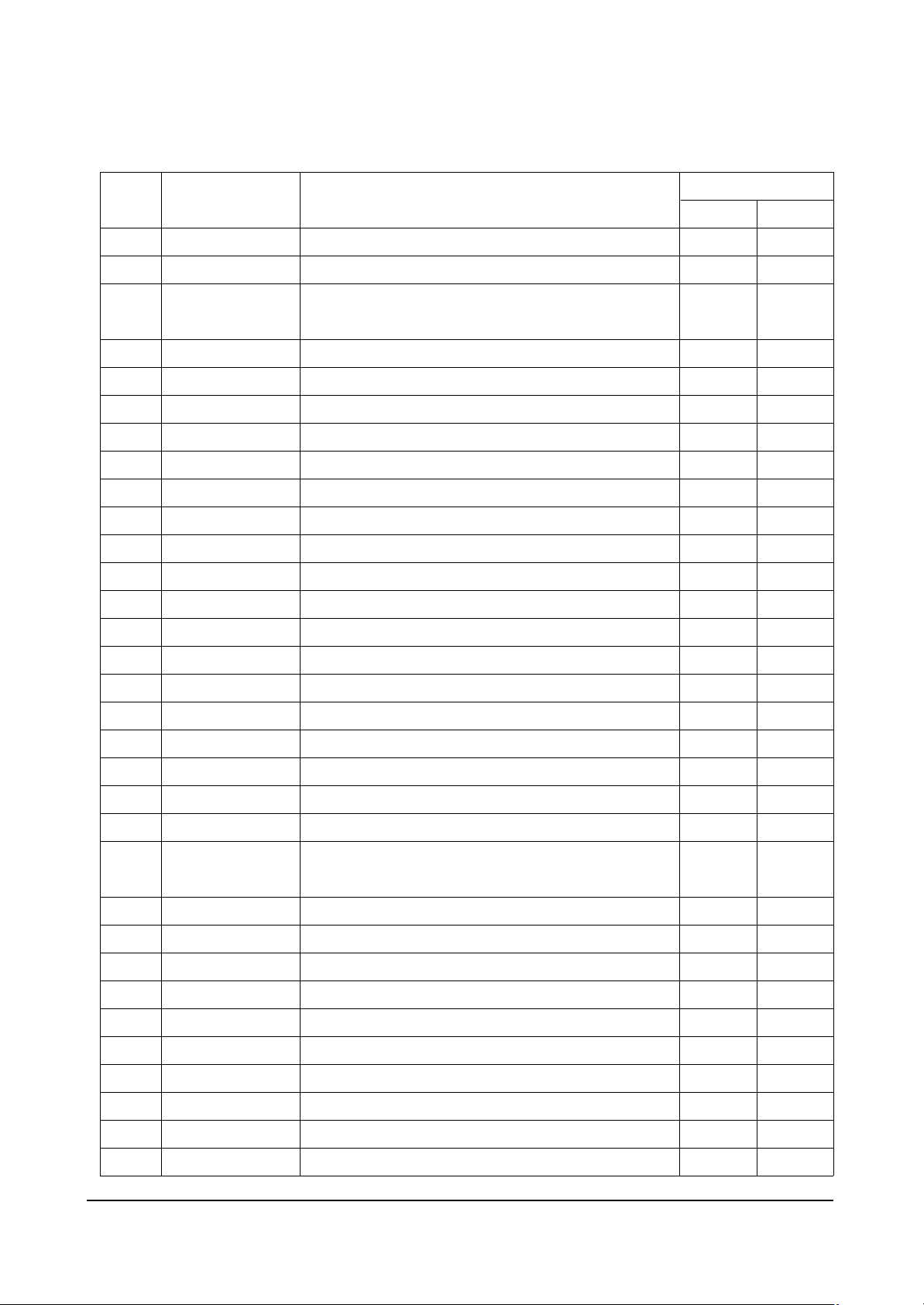
PIN NO
33
34
35
36
37
38
39
40
41
42
43
44
45
46
47
48
49
50
51
52
53
54
55
56
57
58
59
60
61
62
63
64
SYMBOL
HOUT
FBISO
QSSO/AMOUT
EHTO
PLLIF
IFVO/SVO/DVBO
VP1
CVBS1
GND
CVBS/Y
C
SVM
INSSW2
R2/VIN
G2/YIN
B2/UIN
BCLIN
BLKIN
RO
GO
BO
VDDA
VPE
VDDC
OSCGND
XTLIN
XTLOUT
RESET
VDDP
P1.0/INT1
P1.1/T0
P1.2/INTO
PIN FUNCTION
horizontal output
flyback input/sandcastle output
QSS intercarrier output/AM output in stereo applications or
deemphasis(front-end audio out)/AM output in mono applications
EHT/overvoltage protection input
IF-PLL loop filter
AGC sound IF/inter-external AGC for DVB applications
main supply voltage TV processor
internal CVBS input
ground for TV processor
CVBS3/Y input
chroma input
scan velocity modulation output
2nd RGB/YUV insertion input
2nd R input/V(R-Y) input PR input
2nd G input/Y input
2nd B input/U(B-Y) input PB input
beam current limiter input
black current input/V-guard input
Red output
Green output
Blue output
analog supply of Teletext decoder and digital supply of TVprocessor(3.3 V)
OTP Progamming Voltage
digital supply to core(3.3 V)
oscillator ground supply
crystal oscillator input
crystal oscillator output
reset
digital supply to peryipher(+3.3 V)
port 1.0 or external interrupt 1 input
port 1.1 or Counter/Timer 0 input
port 1.2 or external interrupt 0 input
CHECK VOLTAGE
S-By P-On
 Loading...