

SAMSUNG S24AHEBBCNEVX Service Manual
Model : SR-S25/26NTA
SR-S24/25/27FTA
SR-S24/25/27DTA
REFRIGERATOR CONTENT
1. Product Specifications
2. Safety Warnings
3. Specifications of Electric Components
4. Electric Circuit Diagram
5. External Size and Designations
6. Refrigeration Cycle and Cool Air Circulation
7. Function and Usage of Refrigerator
8. Circuit Operation Theory
9. Inverter Component List
10. Troubleshooting
11. Instruction of ICE-MAKER Operation and
Troubleshooting
12. References
13. Disassembly Method of the Refrigerator
14. Assembly and Disassembly of Hinge-Upp
AssÕy
15. Exploded View of Refrigerator and List
16. Assembled State of Machine Room
17. Disassembly of PCB Panel and Assembly
of Internal Components
18. Installation of the Water Dispenser Line
19. PCB Circuit Diagram and Service
Components LIST
20.
Specifications of Major Components in Circuit
1
2
4
6
10
15
17
25
36
37
54
62
67
70
71
115
116
117
119
122

272, Oseon-Dong, Kwangsan-Gu,
Kwangju-City, Korea, 506-253
TEL : (062)950-6811, 6812
FAX : (062)950-6829
Samsung Electronics Co., Ltd.
Refrigerator Division 1998. 4
Printed in Korea
DA68 - 60330B REV (0.1
)
ELECTRONICS
Read all instructions before using this product and keep to the instructions
in order to prevent danger or property damage.
2. SAFETY WARNINGS
2
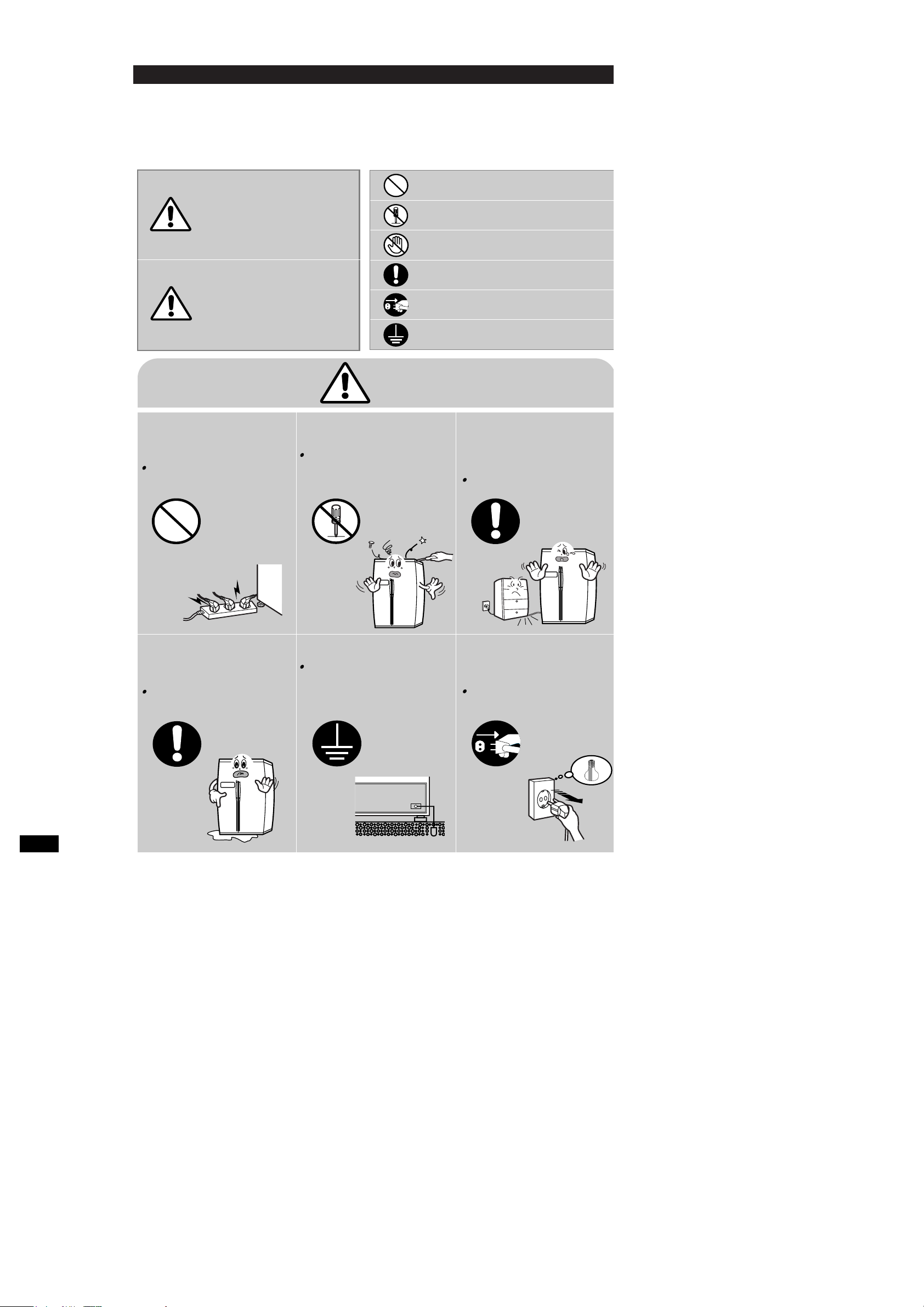
CAUTION/WARNING SYMBOLS DISPLAYED
SYMBOLS
Indicates that a
danger of death
or serious injury
exists.
Indicates that a risk
of personal injury
or material damage
exists.
means ÒProhibitionÓ.
means ÒDo not disassembleÓ.
means ÒNo contactÓ.
means ÓThe things to
be followedÓ.
means ÒEarth to prevent Electric
shockÓ.
means ÒPower cord should be
unplugged from the consentÓ
Do not insert the power plugs
for many products at the
same time.
May cause abnormal
generation of heat or fire.
Do not disassemble,
repair or alter.
It may cause fire or abnormal
operation which leads to injury.
Do not bend the power cord
with excessive force or do not
have the power cord pressed
by heavy article.
May cause fire.
Do not install the refrigerator
in the wet place or the place
which water splashes.
Deterioration of insulation of electric
parts may cause electric shock or fire.
Be sure the earth.
If earthing is not done, it will cause
breakdown and electric shock.
(please refer to page 6).
Pull the power plug out for
exchanging the interior lamp
of the refrigerator.
It may cause electric shock.
Warning
Warning
Caution
Prohibition
Do not
disassemble
Earth
Unplug
3
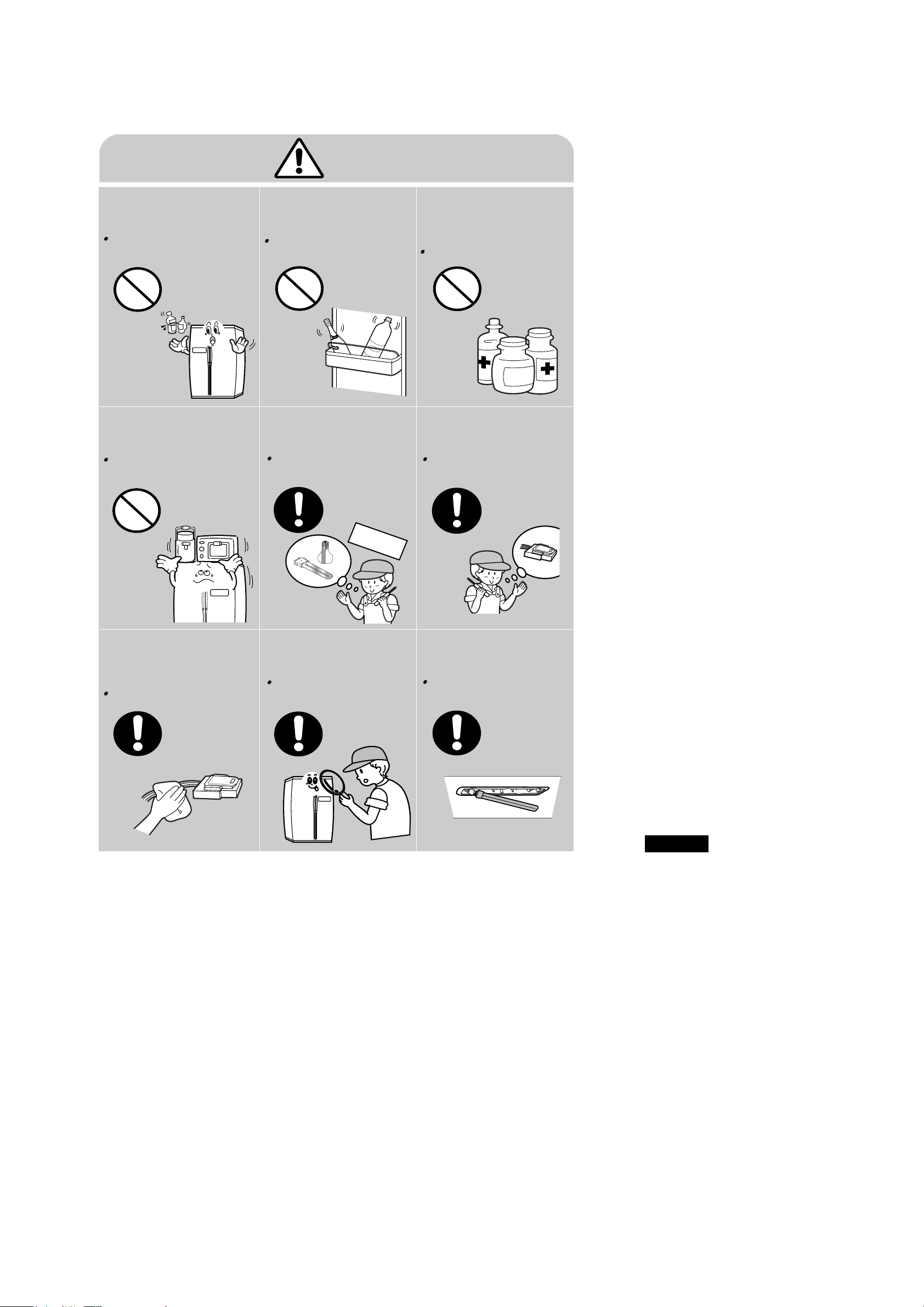
Do not put bottles or kinds of
glass in the freezer.
Freezing of the contents may inflict
a wound.
Do not store narrow and
lengthy bottles or foods in a
small multi-purpose room.
It may hurt you when refrigerator door
is opened and closed resulting in falling
stuff down.
Do not store pharmaceutical
products, scientific materials,
etc., in the refrigerator.
The products which temperature control
shall not be stored in the refrigerator.
Do not store articles on the
product.
Opening or closing of the door may
cause throwing down which may
inflict a wound.
Use the rated components
on the replacement.
Check the correct model, rated
voltage, rated current, operating
temperature and so on.
On repair, make sure that the
wires such as harness are
bundled tightly.
Bundle tightly wires in order not to
be detached by the external force and
then not to be wetted.
Check if there is any trace
indicating the permeation
of water.
If there is that kind of trace, change
the related components or do the
necessary treatment
such as taping
using the
insulating tape.
After repair, check the
assembled state of
components.
It must be in the same assembled
state when compared with the state
before disassembly.
On repair, remove completely
dust or other things of
housing parts, harness parts,
and check parts.
Cleaning may prevent the possible
fire by tracking or short.
Caution
Prohibition
Prohibition
Prohibition
Prohibition
Rated
components

Read all instructions before using this product and keep to the instructions
in order to prevent danger or property damage.
2. SAFETY WARNINGS
2
CAUTION/WARNING SYMBOLS DISPLAYED
SYMBOLS
Indicates that a
danger of death
or serious injury
exists.
Indicates that a risk
of personal injury
or material damage
exists.
means ÒProhibitionÓ.
means ÒDo not disassembleÓ.
means ÒNo contactÓ.
means ÓThe things to
be followedÓ.
means ÒEarth to prevent Electric
shockÓ.
means ÒPower cord should be
unplugged from the consentÓ
Do not insert the power plugs
for many products at the
same time.
May cause abnormal
generation of heat or fire.
Do not disassemble,
repair or alter.
It may cause fire or abnormal
operation which leads to injury.
Do not bend the power cord
with excessive force or do not
have the power cord pressed
by heavy article.
May cause fire.
Do not install the refrigerator
in the wet place or the place
which water splashes.
Deterioration of insulation of electric
parts may cause electric shock or fire.
Be sure the earth.
If earthing is not done, it will cause
breakdown and electric shock.
(please refer to page 6).
Pull the power plug out for
exchanging the interior lamp
of the refrigerator.
It may cause electric shock.
Warning
Warning
Caution
Prohibition
Do not
disassemble
Earth
Unplug

3
Do not put bottles or kinds of
glass in the freezer.
Freezing of the contents may inflict
a wound.
Do not store narrow and
lengthy bottles or foods in a
small multi-purpose room.
It may hurt you when refrigerator door
is opened and closed resulting in falling
stuff down.
Do not store pharmaceutical
products, scientific materials,
etc., in the refrigerator.
The products which temperature control
shall not be stored in the refrigerator.
Do not store articles on the
product.
Opening or closing of the door may
cause throwing down which may
inflict a wound.
Use the rated components
on the replacement.
Check the correct model, rated
voltage, rated current, operating
temperature and so on.
On repair, make sure that the
wires such as harness are
bundled tightly.
Bundle tightly wires in order not to
be detached by the external force and
then not to be wetted.
Check if there is any trace
indicating the permeation
of water.
If there is that kind of trace, change
the related components or do the
necessary treatment
such as taping
using the
insulating tape.
After repair, check the
assembled state of
components.
It must be in the same assembled
state when compared with the state
before disassembly.
On repair, remove completely
dust or other things of
housing parts, harness parts,
and check parts.
Cleaning may prevent the possible
fire by tracking or short.
Caution
Prohibition
Prohibition
Prohibition
Prohibition
Rated
components

Specification
917
mm
884
mm
1783mm(SR-S24FTA, SR-S25NTA)
917
mm
929
mm
1783mm(SR-S25/27FTA(DTA), SR-S26NTA)
INTERMITTENT REFRIGERATOR
HFC-134a
200gr
4STAR
1. Product Specifications
Items
1
Dimension
(Width x Depth x Height)
Rated Voltage & Frequency
Rated Power Dissipation, Motor
Rated Power Dissipation, Heater
Type of Refrigerator
Refrigerant
Refrigerant Mass
Freezing Capacity
Weight
Available
Capacity
TOTAL
FREEZER
REFRIZERATOR
Models
SR-S24/25/27FTA
652 / 701 / 753
233 / 254 / 276
419 / 447 / 477
SR-S24/25/27DTA
656 / 702 / 754
233 / 254 / 276
423 / 448 / 478
SR-S25/26NTA
674 / 720
251 / 272
423 / 448
SR-S24/25/27FTA
134kg / 139kg / 141kg
SR-S24/25/27DTA
134kg / 139kg / 141kg
SR-S25/26NTA
125kg / 129kg
110~115V/60HZ 127V/60HZ 220V/50, 60HZ 240V/50HZ
228W
382W
18
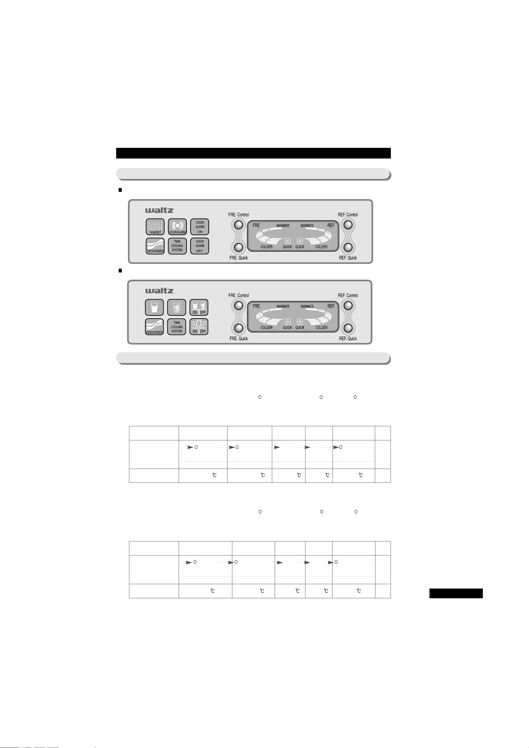
7. Function and Usage of Refrigerator
7-1. Panel Display
Basic type (
NTA
)
External type (
FTA/DTA
)
Change in the
display lamp
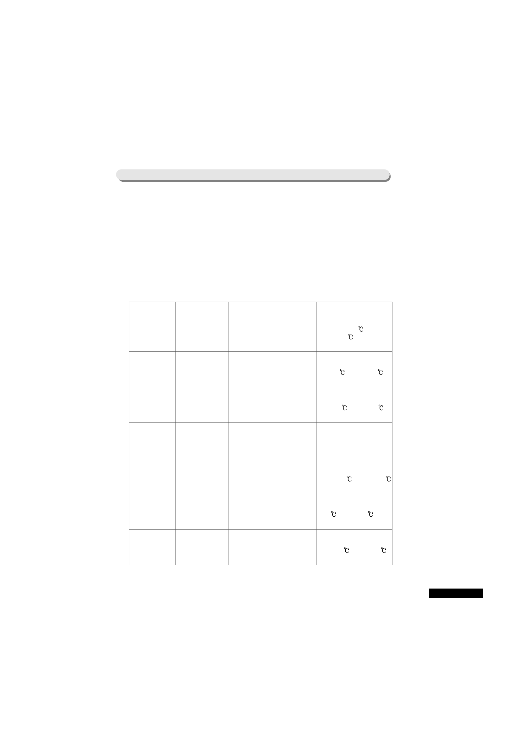
7-2. Temperature-Control function
1. Temperature-Setting Function of Freezer
1) At the first POWER ON, ÒMEDIUMÓ (3rd step) is automatically selected.
2) Select the temperature among five steps, WARMER, (WARMER-MEDIUM), (MEDIUM), (MEDIUM
-COLDER), and COLDER by pushing one button.
3) On pushing the button for temperature-setting in freezer, light on the display panel is moved in order from
ÒWARMERÓ to ÒCOLDERÓ.
Item At the first POWER ON 1st push 2nd push 3rd push 4th push Remark
(MEDIUM) (MEDIUM-COLDER) COLDER WARMER (WARMER-MEDIUM)
app. -19 app. -20 app. -21 app. -16 app. -17.5
2. Temperature-Setting Function of Refrigerator
1) At the first POWER ON, ÒMEDIUMÓ (3rd step) is automatically selected.
2) Select the temperature among five steps, WARMER, (WARMER-MEDIUM), (MEDIUM), (MEDIUM
-COLDER), and COLDER by pushing one button.
3) On pushing the button for temperature-setting in refrigerator, light on the display panel is moved
in order from ÒWARMERÓ to ÒCOLDERÓ.
Change in the
display lamp
Item At the first POWER ON 1st push 2nd push 3rd push 4th push Remark
(MEDIUM) (MEDIUM-COLDER) COLDER WARMER (WARMER-MEDIUM)
app. 2 app. 0.5 app. -1 app. 5 app. 3.5
Specified temperature
in the freezer
Specified temperature
in the refrigerator
17

18
Notice
The specified temperature in the above table, from data when measured in unload state and at 1/3 H
inside the room, is only to describe the temperature at each step generally. The actual temperature
depends upon the surrounding conditions and the loading state.
Set Power-Freezing and Power-Refrigerating by pushing the separate button.
On pushing the button for power-freezing and for power-refrigerating, selection/cancellation (lamp
on/lamp off) is selected in order.
In spite of the selection of power-freezing or power-refrigerating, the temperature setting in the Freezer
and Refrigerator is not changed.
With the selection of Power-Freezing or Power-Refrigerating, you can change the temperature setting of
the freezer and refrigerator.
1. Power-Freezing Function
1) On the selection of Power-Freezing, COMP and F-Fan operates continuously for 2 hours and 30 minutes.
2) In spite of the Power-Freezing operation, the refrigerator operates according to the current setting.
3) On the finish of Power-Freezing (after continuous operation of COMP and F-Fan for 2 hours and 30 minutes),
lamp indicating Power-Freezing turns off automatically and the freezer operates according to the
temperature setting.
2. Power-Refrigerating Function
1) On the selection of Power-Refrigerating, COMP and R-Fan operates continuously till the temperature inside
the refrigerator becomes about -4.0 .
2) After the temperature inside the refrigerator is to be -4.0 , Power-Refrigerating function stops after 1hour ÒCOLDERÓ operation according to the internal function regardless of the current setting.
3) When the temperature inside the refrigerator does not become -4.0 in spite of the selection of PowerRefrigerating function and the continuous operation of COMP and R-Fan for 2 hours and 30 minutes, PowerRefrigerating stops.
4) On the finish of Power-Refrigerating (after continuous operation for 2 hours and 30 minutes or approach to
-4.0 and then, ÒCOLDERÓ operation for 1 hour), lamp indicating Power-Refrigerating turns off automatically
and the refrigerator operates according to the temperature setting.
5) If the current setting is ÒWARMER-MEDIUMÓ (2nd step) or ÒWARMERÓ (1st step), the lamp indicating
Power-Refrigerating turns off after 1-hour ÒCOLDERÓ operation, but 1-hour ÒMEDIUMÓ operation continues
according to the internal function.
At this time, if the setting is changed, immediately cancel the ÒMEDIUMÓ operation and perform the
operation according to the changed setting condition.
6) If there is no change of setting during 1-hour ÒMEDIUMÓ operation, perform the operation according to the
temperature setting after ÒMEDIUMÓ operation stops.
3. Concurrent selection of Power-Freezing and Power-Refrigerating
1) Each function operates independently. It mean that COMP and F-Fan operate continuously by PowerFreezing regardless of Power-Refrigerating function and COMP and R-Fan by Power-Refrigerating function
are continuously operated till the temperature inside the refrigerator becomes -4.0 .
7-3. Power-Freezing and Power-Refrigerating
Notice
If the temperature inside the freezer is above -10 and that inside the refrigerator is
above 10 such as the case of the first POWER ON, Power-Freezing and Power-Refrigerating will
not work as you can expect. However, this is not the usual case and so, explanation is omitted here.
17
20
7-4. ALARM function
1. Button TOUCH sound (ÒDING-DONGÓ sound)
1) If you push each button on the CONTROL PANEL, ÒDING-DONGÓ sounds to confirm the push.
2) If you push two buttons at one time or if you do other wrong-doings, ÒDING-DONGÓ does not sound.
2. DOOR-OPEN alarm (ÒDING-DONGÓ sound)
1) After two minutes with the door of the freezer or the refrigerator opened, alarm sounds ten times.
2) If the door is still in open in spite of the first ten-time alarm, alarm continues 10 times per minute.
3) The alarm stops immediately when the door of the freezer or the refrigerator is closed.
4) If you select OFF for the alarm (for the model with alarm-off function) (Alarm-lamp out) or if you select OFF
for the alarm while alarming, DOOR-OPEN alarm will stop although the door is in open.
5) In spite of the selection of OFF for the alarm, ÒDING-DONGÓ for BUTTON-TOUCH operates normally.
3. Forced-operation and Forced-defrost alarm (ÒBEEPÓ sound)
1) On the selection of Forced-operation and Forced-defrost, ÒBEEPÓ alarm will sound.
2) On the selection of Forced-operation, alarm will continue until the automatic cancellation (after 24-hour
Forced-operation) or till the cancellation function is selected.
3) Also, alarm for Forced-defrost continues until the finish of Forced-defrost (including the pause time) or the
selection of the cancellation.
7-5. Defrost function
1. On the first POWER ON, concurrent defrost for freezer and refrigerator operates
after the accumulated operation time for COMP ON is above 4 hours.
2. Since then, defrost interval will vary from 6 hours to 48 hours according to the operation and
the surrounding conditions.
3. After finish of the first defrost, PRE-COOL function operates for 20 minutes at the start of the
defrost to minimize the temperature increase caused by the defrost. However, the PRECOOL function depends on the temperature inside the refrigerator at the start of the defrost.
4. If the temperature inside R-room is above 0 , PRE-COOL function operates, but if the
temperature inside R-room is below 0 , PRE-COOL function does not operate. In case of F
room, if the temperature is above -21 , PRE-COOL function operates and if below -21 , the
function does not operated.
5. In the above 4, if the temperature of F-room is above -21 (PRE-COOL function condition),
PRE-COOL function will be operated both at F and R-room regardless of the condition inside
R-room. If the case is only about R-room, PRE-COOL function will be operated
independently. It means that PRE-COOL function will be operated only in R-room when
only R-room is in the condition for PRE-COOL.
19

7-6. TEST function
TEST function is for quality control of PCB and the product, in-process control, and SVC.
After check of the function of the product by the selection of TEST S/W, POWER should be turned ON
again to perform self-diagnostic function.
1. Forced-Operation function
1) If you select button on MAIN PCB one time, COMP operates immediately without 5-minute DELAY.
So, attention should be paid because if you perform Forced-operation at the COMP-OFF time, OVER LOAD
may occur.
2) On the selection of Forced-operation, ÒCOLDERÓ for the freezer and ÒCOLDER-MEDIUMÓ for the
refrigerator are selected automatically, COMP and F-Fan are operated on continuous basis, and R-FAN
in the refrigerator is controlled by ÒO(MEDIUM-COLDER)Ó setting.
3) Forced-operation is effective only for 24 hours. It means that, 24 hours after the start of Forced-operation,
concurrent defrost in freezer and refrigerator is conducted automatically and normal operation
starts according to the setting for freezer and refrigerator.
4) To cancel Forced-operation, turn ON again after POWER OFF (RESET) or select TEST CANCELLATION
MODE as described in the below Ò3Ó.
5) On Forced-operation, alarm (0.5 seconds ON/0.5 seconds OFF) continues to the finish of Forced-operation.
There is no cancellation way.
2. Forced-defrost function
1) If you push TEST button one more in Forced-operation state, Forced-operation is immediately canceled and
defrost function operates in refrigerator.
2) At this time, BEEP alarm will sound for 3 seconds at the start and continues on 0.75 seconds ON/0.25
seconds OFF basis during R Forced-defrost operation.
3) If you allow the above R-defrost function to operate, normal operation will start after the finish of the
defrost.
4) If you push TEST button one more in R Forced-defrost operation, concurrent defrost for R and F-room
operates.
5) Also, BEEP alarm will sound for 3 seconds at the start of concurrent R and F-defrost and continues on 0.25
seconds ON/0.75 seconds OFF basis by the finish of concurrent R and F-defrost.
3. Test Cancellation Mode
1) If you push TEST button one more in concurrent R and F-defrost, concurrent defrost will stop and normal
operation will start.
Notice
TEST function will operate STEP BY STEP and so, it is not possible to change from 1 STEP (Forcedoperation) to 4 STEP (TEST CANCELLATION MODE). You should go through all STEP to perform the
desired function. It is preferred to POWER ON after OFF on operation of TEST function.
2019
22
7-7. Self-Diagnosis Function
1. Self-Diagnosis Function on the first POWER-ON
1) On the first Power-on, lamps are ALL ON and self-diagnosis function operates internally.
2) If there is no fault on the self-diagnosis, DISPLAY will show the first normal state.
3) If there is any fault on the self-diagnosis, the relevant LED will flicker and alarm will sound.
4) ERROR (indicating fault) display by the self-diagnosis will continue till all the relevant problems is fixed or
the self-diagnosis is canceled.
5) When the relevant problems is solved, DISPLAY will return to the normal MODE.
6) After fixation of refrigerator, power should be off and on again to check whether the fault is corrected.
7) So, if there is a need to check SENSOR OPEN & SHORT for A/S, sensor can be checked through the selfdiagnosis operation by power-off and on.
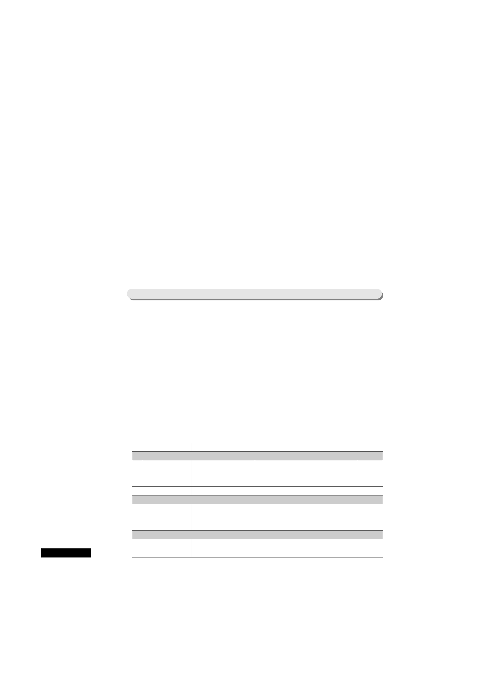
8) If there is any problem, the relevant DISPLAY is as follows.
No Item Relevant LED Problem Remark
01
02
03
04
05
06
07
ICE-MAKER
SENSOR
Temperature setting in
the refrigerator
ÒWARMERÓ (1st step)
OPEN and SHORT type problem with
sensor located at the bottom of ice tray -
problem with wire connection
Temperature by sensor is
above +50 and
below - 50 on the model
with Ice-Maker
R-Room
R-Sensor
Temperature setting in
the refrigerator
ÒWARMER-MEDIUMÓ
(2nd step)
Detach of R-room sensor housing,
contact problem, wire-snapping, Short,
R-Sensor fault and so on.
Problem display when
temperature by R-sensor is above
+ 50 and below - 50
on the model with Ice-Maker
R-Room
Defrost-Sensor
Temperature setting in
the refrigerator
ÒMEDIUMÓ (3rd step)
Detach of R-room sensor housing,
contact problem, wire-snapping, Short,
R-Sensor fault and so on.
Problem display when
temperature by R defrost-sensor is
above + 50 and below - 50 on
the model with Ice-Maker
ICE-MAKER
KIT
Temperature setting in
the refrigerator
ÒCOLDERÓ (4rd step)
Problem with MICRO S/W, Motor,
Gear, and other wiring system inside
Gear Box
When normal operation does not
return in spite of 3 Eject operation
on the model
with Ice-Maker
Ambient
Sensor
Temperature setting in
the freezer
ÒWARMERÓ (1st step)
Detach of Ambient-Sensor housing
inside PCB Base at the top of the
refrigerator, Contact problem, Wire-
Snapping, Short, Sensor fault and so on
Problem display when
temperature by Ambient-sensor
is above + 50 and below - 5000
on the model with ice-maker
F-Room
F-Sensor
Temperature setting in
the freezer
ÒWARMER-MEDIUMÓ
(2nd step)
Detach of F-Room Sensor housing inside
PCB Base at the top of the refrigerator,
Contact problem, Wire-Snapping,
Short, Sensor fault and so on
Problem display when
temperature by F-sensor is above
+ 50 and below - 50 on the
model with ice-maker
F-Room
Defrost Sensor
Temperature setting in
the freezer
ÒMEDIUMÓ (3rd step)
Detach of Defrost-Sensor housing
inside the evaporator of F-Room,
Contact problem, Wire-Snapping,
Short, Sensor fault and so on
Problem display when
temperature by F Defrost-sensor
is above + 50 and below - 50 on
the model with Ice-Maker
Note : This self-diagnosis operates when there is OPEN and SHORT type problem with Sensors. If the
changes in Sensor are within the ranges of the temperature described in the remarks, they are not
judged to be fault and the appliance operates normally.
21
7-8. Load state display function
1. If you push buttons for ÒPOWER-FREEZINGÓ and ÒPOWER-REFRIGERATINGÓ for 3 seconds
during the normal operation, all the temperature-setting DISPLAY for the freezer and refrigerator
will be on. At this time, if you withdraw finger from the buttons, the temperature-setting
DISPLAY for the freezer and refrigerator will be ALL ON/OFF for about 2 seconds at 0.5-second
interval. At this time, if you push button for the temperature-setting for the refrigeration
during ON/OFF, load state display function will start (with ÒDING-DONGÓ alarm).
2. Load state display MODE shows the load that MICOM signal is outputted. But, it means the
output of MICOM signal. It does not show whether the load is actually operated. It means that,
in spite of DISPLAY showing the operation of load, there is a possibility of none-operation by
fault in the actual load or in RELAY on PCB. So, this function can be practicable on A/S.
3. Display continues for 30 seconds. After 30 seconds, the former-setting state will start
automatically.
4. The relevant DISPLAY showing load state are as follows.
2. Self-Diagnosis function during the normal operation
1) If you push buttons for ÒPOWER-FREEZINGÓ and ÒPOWER-REFRIGERATINGÓ simultaneously for about 3
seconds during the normal operation, ALL ON/OFF in the temperature-setting DISPLAY will continue for
about 2 seconds at 0.5-second interval.
If you push buttons for ÒPOWER-FREEZINGÓ and ÒPOWER-REFRIGERATINGÓ simultaneously for about 5
seconds, including 2 seconds for LED ON/OFF, self-diagnosis function is selected.
2) At this time, the refrigerator will return to the self-diagnosis operation with ÒDING-DONGÓ alarm.
3) While the self-diagnosis function is in operation, the self-diagnosis will be performed in order from
ÒCOLDERÓLED of the freezer with ALL ON of the temperature-setting display for the freezer and refrigerator .
4) On ERROR, display will continue for 30 seconds and then, the refrigerator will return to the normal
operation state regardless of fixation of the relevant component. (With ÒDING-DONGÓ alarm)
5) Button push cannot be inputted during the self-diagnosis operation.
6) Among the items of the self-diagnosis, ERROR CHECK of ICE-MAKER SENSOR and ICE-MAKER function
will be done only on the model with the ICE MAKER.
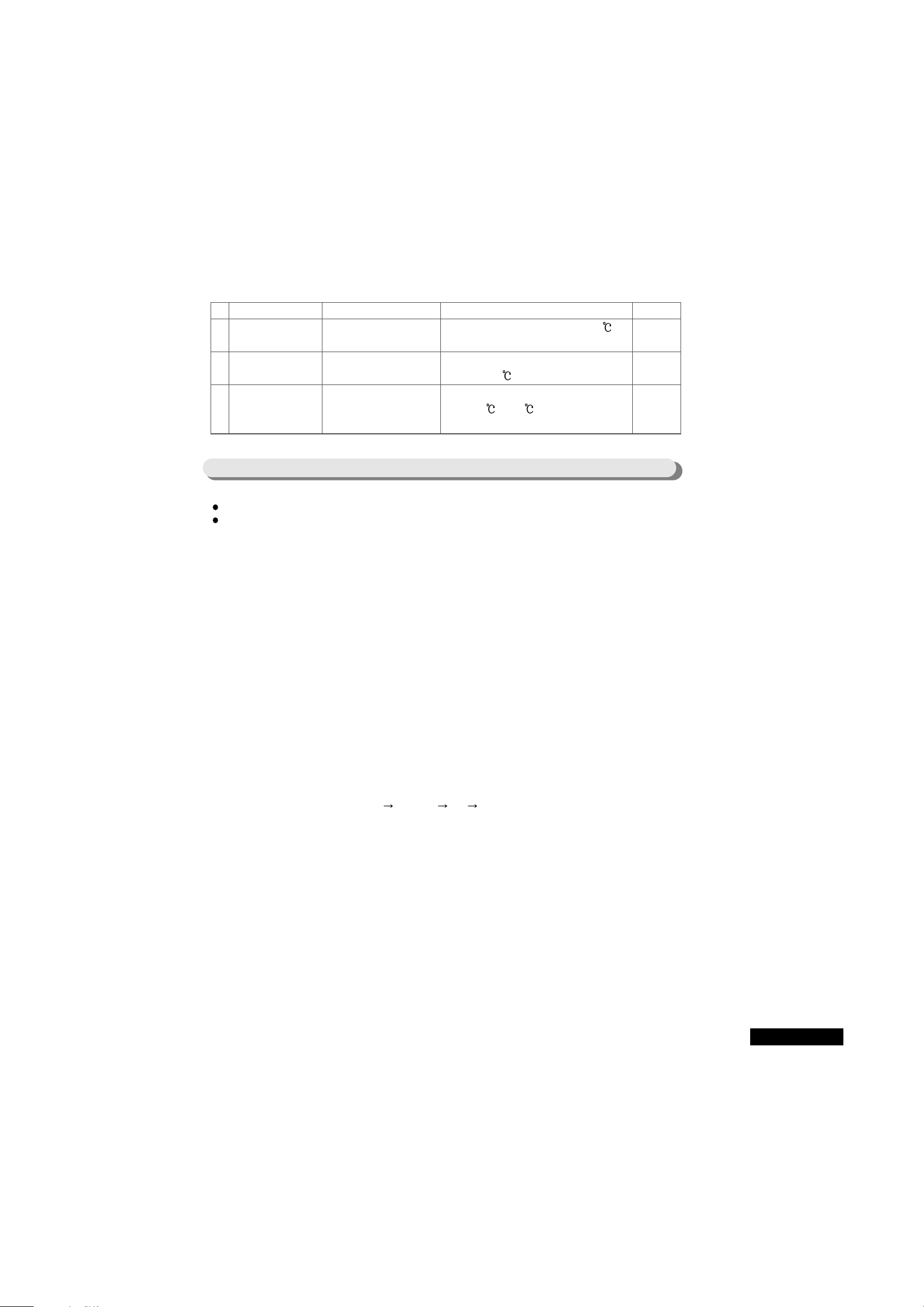
No Item Relevant DISPLAY LED Meaning Remark
Load related with the freezer
1 COMP Freezer ÒWARMERÓ(1st step) On COMP operation, relevant LED ON
2 F-FAN Freezer ÒWARMER-MEDIUMÓ On F-FAN operation, relevant LED ON
(2nd step)
3 F-Defroster HEATER Freezer ÒMEDIUMÓ (3rd step) On F-Defroster HEATER operation, relevant LED ON
Load related with the refrigeration
4 R-FAN Refrigerator ÒWARMERÓ (1st step) On R-FAN operation, relevant LED ON
5 R-Defroster HEATER Refrigerator R-Defroster HEATER operation, relevant LED ON
ÒWARMER-MEDIUMÓ (2nd step)
Mode display
6 START MODE ÒPOWER-FREEZINGÓ If normal freezing does not operate on the first
(First mode) power on, relevant LED ON
2221
24
No Item Relevant DISPLAY LED Meaning Remark
7 Overload condition ÒPOWER-REFRIGERATIONÓ If the ambient temperature is above 35 ,
relevant LED ON
8 WARMER-temperature Freezer ÒCOLDERÓ If the ambient temperature is below
condition (5th step) 17 , relevant LED ON
9 Normal condition No display LED among Normal operation state Ambient temperature is
3 MODE displays means between 18 and 34 and normal freezing state
normal MODE
These functions are limited only to the MODEL that ice and water can be obtained without opening of DOOR.
Among the functions of this ice dispenser, all functions are operated by the mechanical system except the
regulation of CUBE RELAY for obtaining of cube ice and the regulation of light in the DISPENSER, which are
regulated by MICOM.
1. Light ON/OFF function
1) If you push button for Light ON/OFF on DISPLAY, lamp in the DISPENSER will be ON/OFF. To prepare
the case of using at night, lamp in the DISPNSER will be regulated through LIGHT RELAY on MAIN PCB
according to button selection.
2) ON/OFF is toggled by 1 button and it is limited to the MODEL with DISPENSER (SR-S24FTA).
3) As a means of safety, it there is no OFF signal for 20 seconds after lamp selection, lamp turns off
automatically.
4) To turn on the lamp again, push the buttons for lamp ON/OFF.
5) On the first POWER ON, OFF function will be operated.
2. CRUSHED ICE / CUBE ICE / OFF selection function
1) This function is to operate CRUSHED ICE/CUBE ICE/OFF in order by user selection on DISPLAY. By
pushing one button, CRUSHED ICE CUBE ICE OFF CRUSHED ICE is selected in order.
2) On the first POWER ON, CRUSHED ICE is automatically selected.
3) On the selection of CRUSHED ICE, operate GERADE MOTOR to get CRUSHED ICE in the outside when ice
is made in the ice maker and ice LEVER is operated.
4) On the selection of CUBE ICE, operate GERADE MOTOR and ICE SOLENOID to get CUBE ICE in the
outside when ice is made in the ice maker and ice LEVER is operated.
5) If you turn off all display lamp for ÒCRUSHED ICEÓ and ÒCUBE ICEÓ by pushing button for ice, no ice is
made because of stop of ICE MAKER function.
7-9. ICE DISPENSER and WATER DISPENSER function(SR-S24FTA)
23

(1) At the moment of selection of stop function, ice-making function stops, but on eject, return to
horizontality, and water-supply, stop state will be maintained after finish of water-supply.
(2) When OFF function is selected, ice-making function stops. If you push button to select CRUSHED ICE
or CUBE ICE, ICE-MAKER will continue to operate from the stop of ice-making. (This means that icemaking function does not operate from the first.)
(3) In spite of operation of OFF function, ice LEVER will operate normally. This is not the disorder. So, ice
left in the tray of the ice-maker can be used normally. On operation of ice LEVER, GERADE MOTOR will
operate normally and CUBE ICE can be obtained. (On operation of OFF function, only CRUSHED ICE
can be obtained.)
(4) If you want CUBE ICE from the ice left in the tray during OFF function operation, push the button to
select CUBE ICE, obtain the ice and then, operate OFF function again.
3. WATER DISPENSER function
1) This function is directly connected to city water and water can be obtained from WATER SOLENOID
VALVE by pushing WATER LEVER.
Since there is no function regulated by MICOM PCB, if there is any problem with water dispenser function,
check solenoid, connector, and water-supply state.
Notice
With DOOR of freezer open, ice cannot be obtained. This is to prevent from dropping ice into floor
when DOOR of freezer opens and ice LEVER is pushed. Contact point in DOOR S/W is used as
sensor for opening state of DOOR of freezer. Water dispenser is operated normally regardless of
opening of DOOR.
2423
67
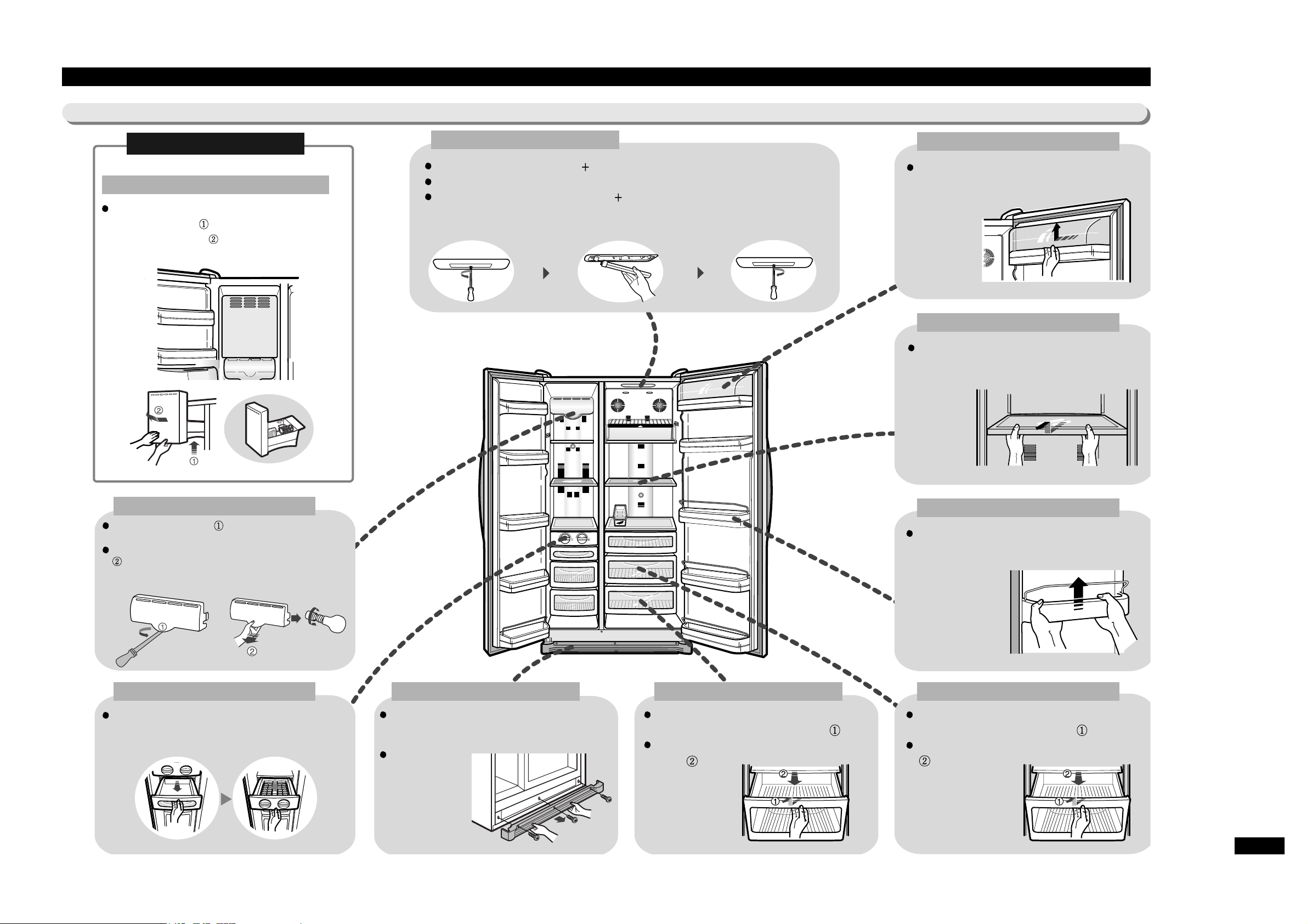
13. Disassembly method of the refrigerator
13-1) How to disassemble the freezer and refrigerator
FTA / DTA
Ice-maker
Interior Lamp(FRE)
While supporting the ice-maker at front, lift
it slightly toward direction and pull it
straight out toward direction.
While pushing toward direction using(-) driver
or the likes, make the lamp cover free.
Remove the lamp cover by pulling it down toward
direction while holding the back of the cover.
After replacement of the lamp, push the font of the
lamp cover back and then the back.
Case-Baskel and Tray Ice
After removing the Case-Basket by pulling it
out, pull the Tray Ice out.
Cover-Tray Water
After opening the doors of the freezer and
refrigerator, disassemble the Cover-Tray Water by
turnig three screws.
When assembling
the Cover-Tray
Water, make it fit
to three slots and
assemble by
turning three
screws.
Case-Veg(LOW) and its cover
Disassemble it by drawing it and lifting it
up slightly while holding the knob. ( )
Slide the cover out by pulling it to the
front. ( )
Case-Veg(UPP) and its cover
Disassemble it by drawing it and lifting it up
slightly while holding the knob. ( )
Slide the cover out by pulling it to the front.
( )
Interior Lamp(REF)
Remove the cover by rotating( ) driver.
Remove the lamp by pulling it out and replace new one.
After covering, assemble by rotating( ) driver toward the arrow direction.
Guide-Bottle(REF)
While holding the Guide-Bottle, disassemble
it by lifting it up.
Shelf(REF)
While drawing the shelf out, slide it out by
lifting it up.
Cover-Guard
While pushing the cover to the left, slide it
out by lifting it up.
68
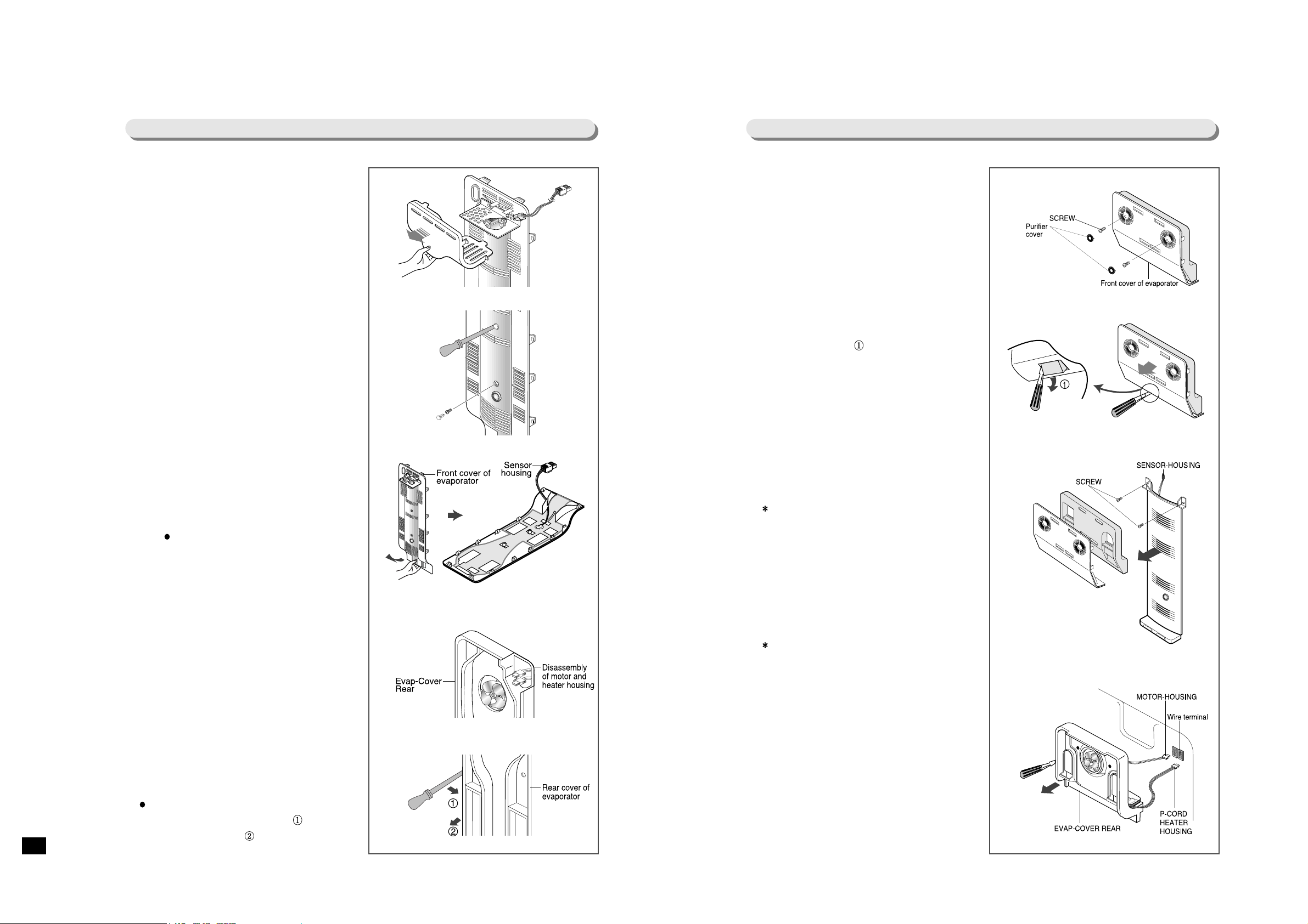
13-2) Disassembly of Evaporator of Freezer
1. After disassembly of the lamp cover for the
freezer, disconnect wire housing from the
lamp socket.
2. Disassemble and remove two cap-screws
using(-) driver or the likes.
3. While holding the bottom of the EVAPCOVER FRONT and drawing it carefully
toward the arrow direction, disassemble
the cover by sliding it out at the raised
spot.( Since the housing for the thermalsensor is located at the rear side of the
cover, be careful during disassembly and
disconnect the housing.)
4. After disassembly of the EVAP-COVER
REAR, disassemble the motor and heater
housing from the wire terminal at the top
side of the cover.
5. After removing two screws of the COVEREVAP REAR, disassemble it by pulling it
out to the front using(-) driver or the likes.
( Slide the cover out by pushing the held
part toward the arrow direction and
drawing it to the front )
13-3) Disassembly of Evaporator of Refrigerator
1. Remove all foods in the refrigerator and
shelves.
Disassemble two purifier covers using(-)
driver or the likes and remove a screw.
2. Detach snaps of the bottom side of the
COVER-EVAP FRONT by inserting(-)
driver into the snaps and rotating it toward
the arrow direction.
After detachment of the snaps of the EVAPCOVER FRONT, disassemble the cover by
pulling it to the front.
3. After detachment of the insulating material,
remove screw of damper cover and
disassemble by pulling it to the front.
( While disassembling the damper cover,
at first disassemble the sensor housing at
the left top.)
4. Disassemble the COVER-EVAP REAR by
deatching the snaps and pulling it out to
the front using(-) driver or the likes.
( While disassembling the COVER-EVAP
REAR, be careful because motor wire is
connected.)
5. Disassemble the motor and heater housing
from the wire terminal at the top side of the
cover.

69
13-4) Temperature controller
SR-S24NTA
SR-S24FTA
Disassemble the temperature controller by
detaching the snaps of the front cover of
the temperature controller using (-) driver
or the likes and pulling it to the front.
Replace PCB base by disassembling the
wire housing connected to PCB and
removing 3 screws.
Assembly is the reverse procedure of
disassembly.
Disassemble the temperature controller by
pulling it out to the front while holding
the bottom side of the front cover of the
dispenser.
Replace PCB base by disassembling the
wire housing connected to PCB and
removing 3 screws.
Assembly is the reverse procedure of
disassembly.
70
14. Assembly and Disassembly of HINGE-UPP ASSÕY
2. Assembling procedure of Hinge-Upp AssÕy
1) Place the Hinge-Upp AssÕyon the Reinf-Hinge Upp according to the direction
and load the Hinge-Upp AssÕywhile rotating it to assemble.
2) After assembly of Fixer-Hinge Upp to Reinf-Hinge Upp, finish the assembly
by rotating toward the direction .
3. Disassembly procedure of Hinge-Upp AssÕy
1) Disassembly is the reverse procedure of assembly.
1. Structure of Hinge-Upp AssÕy
Terminal oscillation frequency
X in(#30)
X out(#31)
4MHz
4MHz
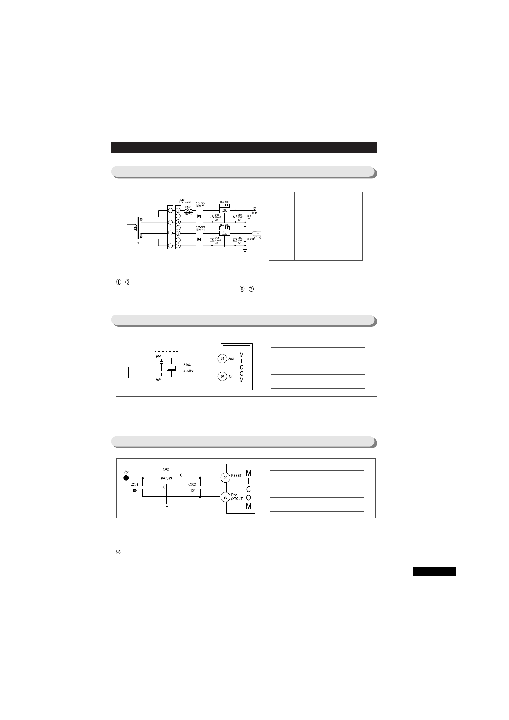
8-1. Power supply part
About AC 9V, pressed at 2nd side of LVT(LOW Volt Transformer), is suspended between CN10
~ and DC 5V is made through constant-voltage IC (KA7805) rectified by Rectifier Diode.
And, about AC 17V is suspended between CN10 ~ and DC 12V is made through
constant-voltage IC(KA7812).
8. Circuit operation theory
8-2. Power generator circuit part
This is a power generator circuit part to generate synchronous CLOCK for information transfer of
MICOM internal degauss and calculate time. On change of spec. of RESONATOR, normal
operation cannot be performed from the result of change of TIMMING system in MICOM.
8-3. RESET circuit part
RESET circuit is to operate overall PROGRAM in the primary state by initializing several parts including
RAM in the internal of MICOM when power is supplied to MICOM as a result of power input or instant
suspension of electric supply. When power is supplied, voltage at RESET Terminal becomes scores of
ÒLowÓstate, when compared to the voltage of Vcc (DC 5V) of MICOM. On the general operation
state,ÓHighÓ (Vcc voltage) state is maintained.
Voltage Circuit used
Vcc Power supply for MICOM
(DC 5V) and peripheral circuit
V12 Power supply to operate RELAY,
(DC 12V) EJECT MOTOR, DISPLAY
Terminal oscillation frequency
Vcc
RESET
DC 5V
DC 5V
GRY
RED
BLK
BLK
BLU
BLU
25

8-4. DOOR S/W sensing circuit
DOOR OPEN/CLOSE of F-room sensing is performed by connecting of CN30 to GROUND, supplying
Vcc (DC 5V) to through resistance R404 (4.7 ) and supplying ÒLowÓ (0V) / ÓHighÓ(5V) to MICOM by
DOOR OPEN/CLOSE of F-room.
DOOR OPEN/CLOSE of R-room sensing is performed by connecting of CN31 to GROUND, supplying
Vcc (DC 5V) to through resistance R403 (4.7 ) and supplying ÒLowÓ (0V) / ÓHighÓ(5V) to MICOM by
DOOR OPEN/CLOSE of R-room.
If there is any problem in DOOR S/W, Fan in the relevant room will not work and alarm function will
operate. So, DOOR S/W should be checked if there is any problem on A/S.
For FAN in the relevant room will stop on DOOR OPEN, if there is any problem in the contact point of
S/W, MICOM will judge that DOOR is opened and stop FAN operation, although DOOR is closed.
8-5. Temperature sensing circuit
SENSOR works on the basis of the characteristics of THERMISTOR with temperature coefficient of
negative resistance that resistance value decrease when temperature is High and resistance value
increase when temperature is low.
R306 ~ R310 and C302 ~ C306 are parts to prevent NOISE.
They have no relation with temperature sensing.
In case of F-SENSOR, when the voltage inputted to MICOM is considered to be Vf, Vf is (Rth Vcc)
/(R303 + Rth). In this equation, Rth is the resistance value of THERMISTOR corresponding to
temperature. See the conversion table of the resistance and voltage of sensor according to the
temperature in the Reference No. 8 of this manual. Use the table on A/S because MICOM Terminal
voltage is also described in the table.
Terminal Voltage MICOM
F-room
On DOOR CLOSE
On DOOR OPEN
5V (HIGH)
0V(LOW)
R-room
On DOOR CLOSE
On DOOR OPEN
0V (LOW)
5V(HIGH)
MICOM Terminal Voltage
PIN #58 (F-SENSOR)
PIN #57 (R-EVA-SENSOR)
PIN #56 (R-SENSOR)
PIN #59 (F-EVA-SENSOR)
PIN #60 (AMBIENT-SENSOR)
Voltage in
MICOM
Terminal is
changed
according to
temperature.
AMBIENT
26
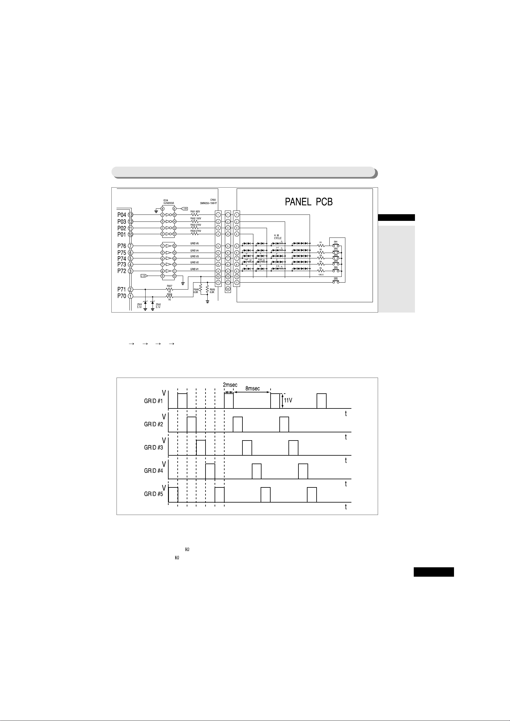
8-6. KEY SCAN and DISPLAY circuit part
1. Running of KEY SCAN and DISPLAY
As shown in the following waveform of each part, ÒHighÓ output is sent in turn from MICOM PIN
#3 #4 #5 #6 #7 for 2 msec at 10msec interval using five Terminal of MICOM NO #3, 4, 5, 6, and 7.
This signal appears at OUTPUT Terminal through INPUT Terminal of IC05 (UDN2981 or UPA2981C).
At this time, PEAK TO PEAK voltage of square-wave is about 11 V (DC RMS 1.5 V) and output waveform
is as follows.
2. KEY SCAN
When GRID #1 waveform is outputted, this signal is supplied to the button for temperature-setting of freezing
room through resistance 10 . At this time, when you push button for freezing room, the signal becomes
decreased by R506 (6.8 ) and about 4.5 V of PEAK TO PEAK voltage is approved to MICOM. After supply
of about 4.5 V of PEAK TO PEAK voltage to MICOM, MICOM can judge that GRID #1 waveform is inputted
and then, change the temperature-setting for freezing room. Like this way, each GRID waveform is perceived.
POWER-
FREEZING
POWER-FREEZING
POWER-
REFRIGERATING
POWER-REFRIGERATING
F, R ROOM
DEODORIZATION
DOOR-SECURING
or CUBE
COLDER-HUMIDITY
or CRUSH
Door-Securing
ONor
CRUSHED/CUBE
POWER REF
POWER FRE
REFRIGERATOR ROOM SETTING
'
FREEZER ROOM SETTING
Door-Securing
OFF or
LIGHT ON/OFF
RED-RED
BLU-BLUE
ORG-ORANGE
BRN-BROWN
PNK-PINK
GRY-GRAY
WHT-WHITE
YEL-YELLOW
BLK-BLACK
PRP-PURPLE
W/BLKWHITE/BLACK
S/BLUSKY BLUE
REFERRENCE
27

8-7. LOAD OPERATION circuit part
When ÒHighÓ signal is supplied to INPUT of IC03 (ULN2003A) at MICOM PIN NO #22 (P15), IC comes to be
turned on. At this time, if V12 (DC 12V) supplied to the lower COIL of COMP RELAY runs into GROUND
through OUTPUT of IC03, magnetic field will occur at CORE and then make contact point ON. This approves
220 V to COMP LOAD to make COMP ON and, if MICOM PIN NO #22 becomes ÒLowÓ state, IC comes to be
TURN OFF state to make current not running to COMP RELAY COIL, to make RELAY contact point OFF state,
and then, finally to stop COMP.
1. Explanation of co-operation of COMP and F, R-Defroster HEATER
RED
COMP load
F-Defroster Heater
R-Defroster Heater
GRY
R-Defroster
Heater
F-Defroster
Heater
RED-RED
BLU-BLUE
ORG-ORANGE
BRN-BROWN
PNK-PINK
GRY-GRAY
WHT-WHITE
YEL-YELLOW
BLK-BLACK
PRP-PURPLE
W/BLKWHITE/BLACK
S/BLUSKY BLUE
REFERRENCE
WHT
PRP
BRN
GRY
YEL
RED
W-BLK
BLU
ORG
WHT
RED
L-BLU
BLK
F-Defroster Heater
F-ROOM LAMP
Circulation Fan
DISPENSER HEATER
DISPENSER LIGHT
SOLENOID-VALVE
Circulation Fan
HOME BAR HEATER
Compressor
R-Defroster Heater
COMP-FAN for basic model
GRN
RED
RED
GRY
RED
RED
RED
RED
GRY
BLK
PRP
Temperature Fuse
Temperature Fuse
RED
RED
ORG
BLU
28
Like the above BLOCK DIAGRAM, LINE of AC 220V is connected to RELAY for COMP and COMMON for
HEATER RELAY, respectively. At this time, if RELAY is not operated, contact point is NC state and RDefroster HEATER RELAY is OFF state. So, LOAD maintains OFF state. If COMP becomes the conditions for
operation and COMP RELAY is operated (move to contact point NO), COMP becomes closed-circuit and
operated and makes power for both ends of F, R-Defroster HEATER OFF state. If F-Defroster HEATER comes
to operate, power for both ends of COMP should be OFF.
Purpose of the application of the above circuit : to block all power for both ends of Defroster-HEATER on the
operation of COMP and to block all power for both ends of COMP on F-Defroster HEATER.
<Co-operation Table>
Operation condition Load condition Remark
COMP and F, R-Defroster HEATER OFF
COMP, Defroster
RELAY ALL OFF
COMP RELAY operation
F-Defroster HEATER operation
COMP ON and F, R-Defroster
HEATER OFF
Block of power for both ends of
F, R-Defroster HEATER
F-Defroster HEATER ON
COMP OFF
Block of power for both ends of
andCOMP
29
Change of temperature in
the Freezer
Change of temperature in
the Refrigerator
When temperature outside
Freezer is below 17 ,
change of compensation
temperature
(condition on low
temperature)
Change of Freezer
NOTCH GAP
(ÒCOLDERÓ on the basis of
ÒMEDIUMÓ)
Change of Freezer
NOTCH GAP
(ÒWARMERÓ on the basis of
ÒMEDIUMÓ)
Change of Refrigerator
NOTCH GAP
(ÒCOLDERÓ on the basis of
ÒMEDIUMÓ)
Change of Refrigerator
NOTCH GAP
(ÒWARMERÓ on the basis of
ÒMEDIUMÓ)
OPTION function Used DIODE
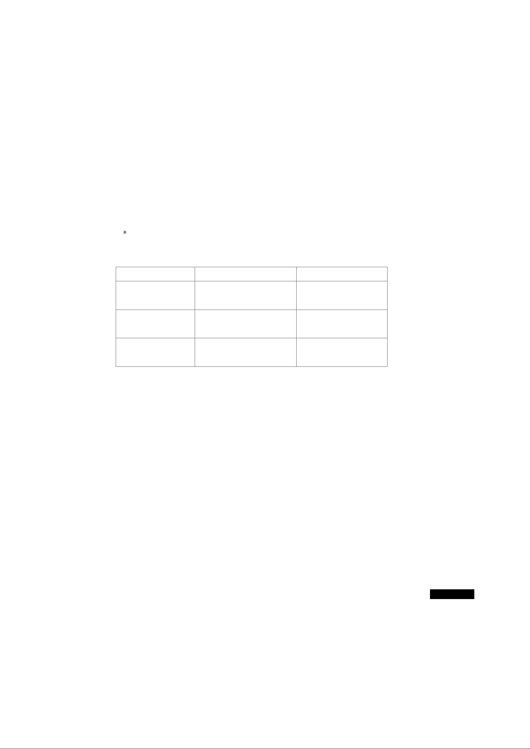
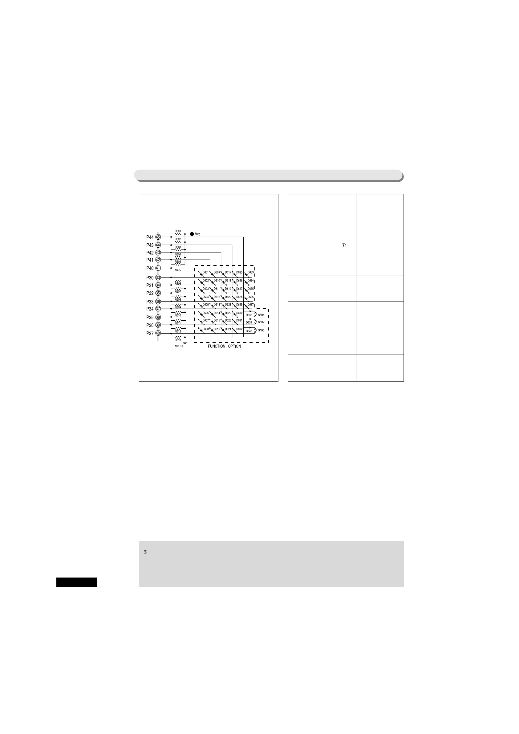
8-8. Various OPTION function
The above circuit is to change the items related with temperature and function using 40 SWITCHING
DIODE on MAIN PCB.
Notice
Since products are released from factory after setting of OPTION functions is finished, no change of
setting is preferred with the exception of the special case. After change of setting, power should
be turned off and on again.
D601, 602, 603, 604
D605, 606, 607, 608
D611, 612
D613, 614
D615, 616
D617, 618
D619, 620
30

Table of Temperature Change of Freezer ( : Relevant DIODE No. used)
Explanation of Example : In case there is a need to change temperature of Refrigerator , change the
temperature according to the following procedures.
Step 1 : Since D605 to D608 are used as DIODE for temperature change of Refrigerator,
check DIODE used at the relevant PCB and the current temperature. For
example, when D605 and D608 are used, it means the change to + 1.0 when
compared with the temperature limit described in the above Table.
Step 2 : Determine the temperature to be adjusted according to judgement with regard to
the request from customers.
For example, if about 2.0 should be lowered,
Step 3 : Calculate the temperature ; since the current OPTION state is +1.0 as shown in
step 1 and 2.0 is to be lowered as shown in step 2, add 1.0 to - 2.0 as follows.
(+ 1.0 ) + (-2.0 ) = -1.0
Step 4 : Find out the relevant DIODE No. in the table corresponding to the calculated
temperature. Since DIODE corresponding to -1.0 is D606, 2.0 can be lowered
by removing two current DIODE, D605 and D608 and inserting D606.
Temperature
change
Temperature Limit
- 0.5
- 1.0
- 1.5
- 2.0
- 2.5
- 3.0
- 3.5
D604 D603 D602
Relevant DIODE No. used
Temperature
change
+ 0.5
+ 1.0
+ 1.5
+ 2.0
+ 2.5
+ 3.0
+ 3.5
+ 4.0
D604 D603 D602
D601
Relevant DIODE No. used
Table of Temperature Change of Refrigerator ( : Relevant DIODE No. used)
Temperature
change
Temperature Limit
- 0.5
- 1.0
- 1.5
- 2.0
- 2.5
- 3.0
- 3.5
D608
D607
D606
D605
Relevant DIODE No. used
Temperature
change
+ 0.50
+ 1.00
+ 1.50
+ 2.00
+ 2.50
+ 3.00
+ 3.50
+ 4.00
D608 D607 D606 D605
Relevant DIODE No. used
31
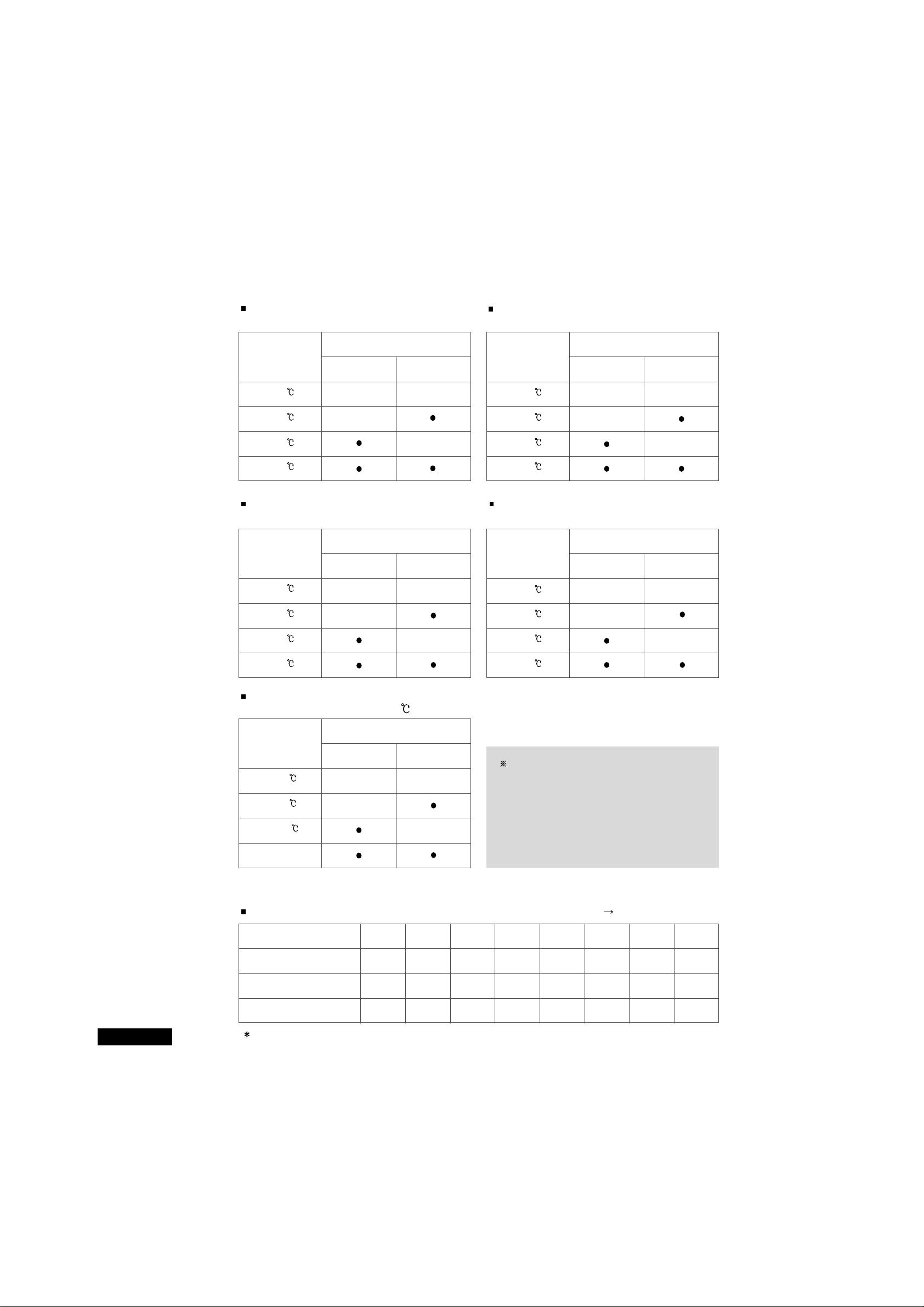
Change of NOTCH GAP of Freezer
(ÒCOLDERÓ on the basis of ÒMEDIUMÓ)
Change of NOTCH GAP of Freezer
(ÒWARMERÓ on the basis of ÒMEDIUMÓ)
Temperature compensation when the
ambient temperature is below 17 .
Temperature
change
- 0.5
- 1.0
+ 0.5
No compensation
D612 D611
Relevant DIODE No. used
Change of NOTCH GAP of Refrigerator
(ÒCOLDERÓ on the basis of ÒMEDIUMÓ)
GAP change
4.0
3.0
5.0
2.0
D618 D617
Relevant DIODE No. used
Change of NOTCH GAP of Refrigerator
(ÒWARMERÓ on the basis of ÒMEDIUMÓ)
GAP change
3.0
2.0
4.0
5.0
D620 D619
Relevant DIODE No. used
GAP change
2.0
3.0
4.0
5.0
D614
D613
Relevant DIODE No. used
GAP change
4.0
2.0
3.0
5.0
D616 D615
Relevant DIODE No. used
Notice
Although there are more OPTIONs except the
above things described, they are not required on
A/S with regard to the function of refrigerator
regulation and so, not described here.
The above things are only the functions related
with the temperature change actually used.
Control of water supply to ICE-MAKER (Change of SOLENOID opening time) use DIP S/W
FTA / DTA
S/W 1
S/W 2
S/W 3
6 sec
OFF
OFF
OFF
5 sec
ON
OFF
OFF
7 sec
OFF
ON
OFF
8 sec
ON
ON
OFF
9 sec
OFF
OFF
ON
12 sec
ON
OFF
ON
15 sec
OFF
ON
ON
23 sec
ON
ON
ON
The refrigerator is released with all S/W1 ~ S/W3 OFF (water supplying time is 7 seconds).
32

Temperature Change of Ice-Making SENSOR for Eject operation
Classification
D635
D636
D637
-10
0
0
0
-11
1
0
0
-12
0
1
0
-13
1
1
0
-14
0
0
1
-9
1
0
1
-8
0
1
1
-7
1
1
1
MODEL OPTION function
This refrigerator can operate 2 MODEL using one MAIN PCB AssÕy. So, since function of PANEL PCB
and MAIN performance function are to be selected to change by MODEL OPTION of MAIN PCB, the
same specification of PCB should be used on replacement of PCB or the following specification of
MODEL OPTION and H/W OPTION should be applied. On change of MODEL OPTION, POWER
should be OFF and ON for normal operation.
<Table for PCB specification>
SR-S25/26NTA
H.M-CYCLE
(Basic)
MO-1,
MO-2
Not used
ICE MAKER OPTION part = not used
C901 ~ C905(104)=JUMP WIRE used
RY74, RY76 = not used
Water supply control DIP S/W = not used
SR-S24/25/27FTA
SR-S24/25/(DTA)
H.M-CYCLE
+
ICE &
WATER
DISPENSER
+
HOME BAR
(WITHOUT
HOMEBAR)
Only MO-2
used
ICE MAKER OPTION part = used (refer
to the following information)
C901 ~ C907 = 104 AXIAL
C/CAPACITOR used
R901 = 12 used
R902,906,907,908 = 1.0 - J used
R903,905 = 10 - J used
R904 = 10 - F used (deviation 1%)
R909,910,911=4.7 - J used
CN90=8P CONNECTOR SMW250-08
used
Water supply control DIP S/W used
D638, 639, 640 used (necessary on the used
of DIP S/W)
MODEL SET function H/W OPTION specification on PCB Remark
Notice
When PCB should be replaced, check the specification described in the above TABLE and use the
regular specification of PCB for normal operation. If possible, avoid remodeling because
function resulted from the change of SPEC may occur.
Information
See the PCB circuit diagram of this manual.
MODEL OPTION
on PCB
33
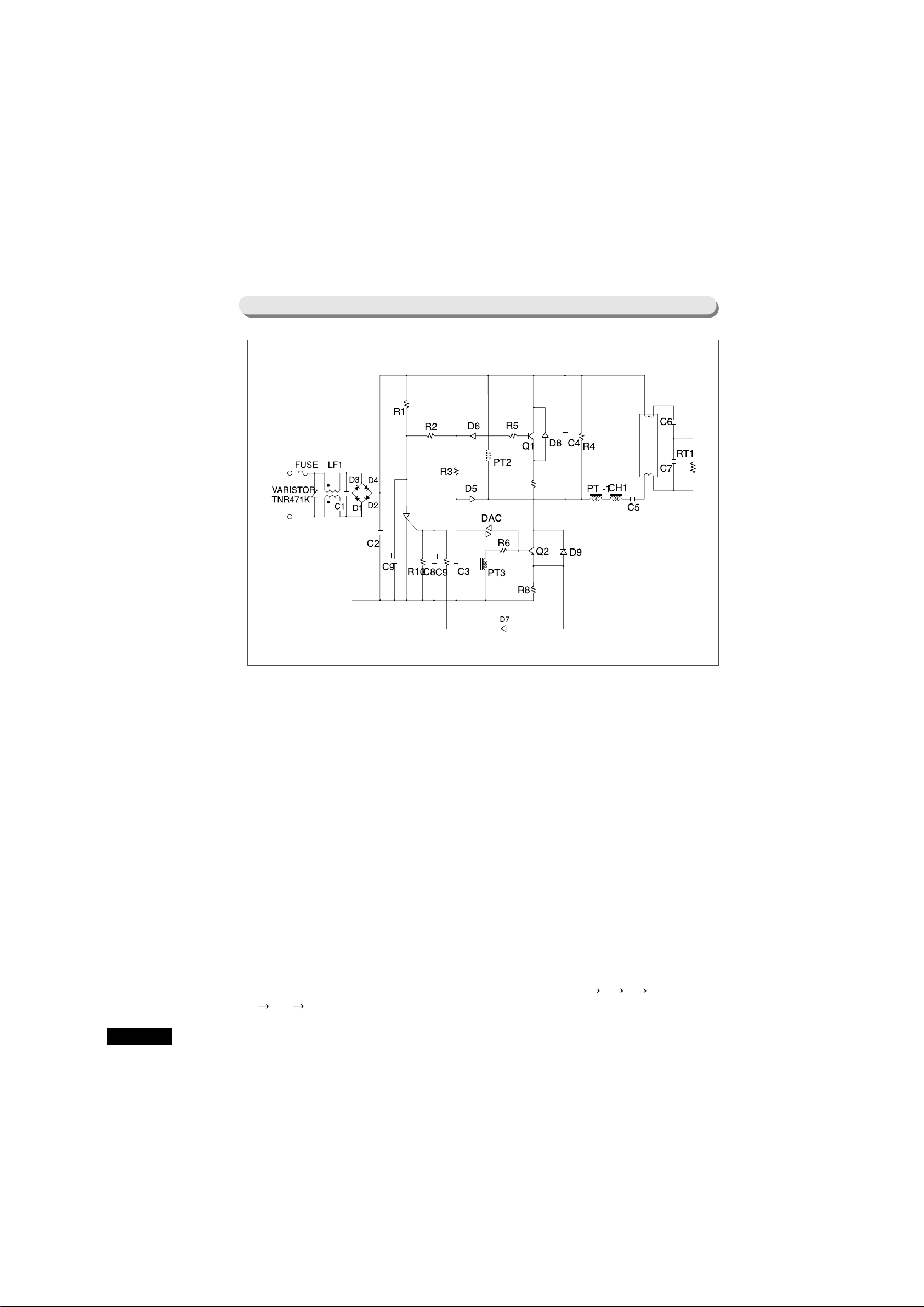
8-10. PCB SUB AssÕy (INVERTER PCB)
1. EMI circuit
COMMON MODE NOISE is attenuated by CHOKE LFI, NORMAL MODE NOISE and D.C
RESISTANCE.
2. Rectifier circuit
Holding voltage is converted to DC voltage by BRIDGE DIODE.
It is ELECTROLYTIC CAPACITOR and composed of balance circuit
3. First starter circuit
The current converted to DC by C2is charged to C3through R3. When more than 35V is charged at C3, the
first switching operation is initiated by sending the current to BASE of Q
2
through DAC R1and D5maintain
enough potential difference between EMITTER and COLLECTOR of TRQ
2
for easy first switching.
4. Switching circuit
Q2becomes ON by the current from DAC and then, the current goes through C6C7C5CH
1
TR(C E). The current sent to PT1is held at PT3and by this holding current, Q2maintains ON state.
Switching circuit is consisted when OSC COIL becomes saturated by line current, counter-electromotive force
occurs at PT
3
, electromotive force is held at PT2, and then, Q1comes to be operated.
34

5. Resonance output circuit
To make the life-span of fluorescent light bulb longer, supply the filament pre-heat current.
Line current is running through filament C
6
RT1filament C5PT1.
Resistance value is increased at PT
1
by running of PTC pre-heat current.
When impedance of PT
1
is Higher than impedance of C7, the current runs toward C7and so, discharge voltage
is permitted to both ends of lamp. And finally, discharge occurs at lamp as a result of resonance of L and C.
After LAMP is ON, the resonance current runs through lamp RT
2C5
PT1.
6. Guard circuit
On abnormal operation of LAMP or abnormal operation of switching circuit, toward D7, more than 0.7 V of
voltage is held at GATE of SCR and so, SCR operates to block power.
When abnormal voltage or over-voltage is held at power part, FUSE at the primary power circuit is gone to
block the power.
35

NO Items Specification EA Remark
1 RESISTOR 2W 5% 150 kohm 1 R
1
2 RESISTOR 1W 5% 120 ohm 1 R
2
3 RESISTOR 1W 5% 560 kohm 2 R3, R
4
4 RESISTOR 1/4W 5% 12 kohm 1 R5, R
6
5 RESISTOR 1/4W 1% 2.35 ohm 2 R7, R
8
6 RESISTOR 1/4W 5% 10 ohm 1 R
9
7 RESISTOR 1/4W 5% 8.2 kohm 1 R
10
8 ELECT CAPACITOR 450V 10 1 C
2
9 ELECT CAPACITOR 6.3V 220 2 C
8
10 PE CAPCITOR 275VAC 0.1 (104) 1 C
1
11 MYLAR CAPACITOR 100V 47 (2J 473K) 1 C
3
12 NPP CAPACITOR 630V 1.0 (2J 102K) 1 C
4
13 MF CAPACITOR 630V 47 (2J 473K) 1 C
5
14 NPP CAPACITOR 630V 8.2 (2J 822K) 1 C
6
15 NPP CAPACITOR 630V 3.3 (2J 332K) 1 C
7
16 GP DIODE 1N4007 7 D1, D2, D3, D4, D5, D6, D
7
17 FASRECOVERY DIODE 1N4937, FR105 2 D8, D
9
18 DIAC N413, NMA64, D30A 1 DAC
19 CHOKE COIL CORE : EE 1916 1 CH
1
COIL : 0.3
L VALUE : 2.6 0.3mH
20 OSC COIL CORE : AMS-08S-N 1 PT
1
TURN : 6:4:4
COIL : 0.3
L VALUE : 50uH OVER
21 NOISE FILTER COIL CORE : UU1116 1 LF
1
COIL : 0.23
L VALUE : 50mH OVER
22 FUSE 250V 2.0A 1 FUSE
(MEDIUM NORMA-TYPE)
23 TRANSISTOR BUH51 2 Q
1
, Q
2
24 SCR S1M 1 Q
3
25 PTC CERA MITE 307C1414BHMAB 1 RT
1
26 PCB 86 50 1
27 WIRE HARNESS PLUR HOUSING : 35151-0410 ÒAÓpart
TERMINAL : 35745, 746, 747 1 (HOUSING
748-0110 couple connecting part)
T.P.A : LOCK 35150-0292
WIRE :
COLOR : BLACK 2, WHITE 2
SIZE : UL1007 AWG20
LENGTH : 85MM
CRIMP HOUSING : BH0640-07 ÒBÓpart (PCB outlet)
CRIMP TERMINAL : BT0604
28 WAFER YW396-03AV 1 INPUT
29 JUMP WIRE 0.6 10MM 2 J
1,J2
30 VARISTOR ANR471D14 1 TNR
31 PE CAPACITOR 630V 10nF(2J103K) 1 C
9
9. Inverter Component list
36
 Loading...