

Samsung S1D2141X01-D0B0 Datasheet
R/G/B VIDEO AMPLIFIER FOR MONITORS S1D2141X01
R/G/B VIDEO AMPLIFIER
The S1D2141X01 is a very high frequency Video amplifier system to be
used in Monitor. It contains 3 matched R/G/B video amplifiers with
blank signal and clamp gate pulse and provides a flexible interfacing to
DC controlled adjustment system
FUNCTIONS
• R/G/B Video Amplifier
• Contrast/SUB contrast control
• Brightness control
• Blank gate/Clamp gate
• Video clamp
ORDERING INFORMATION
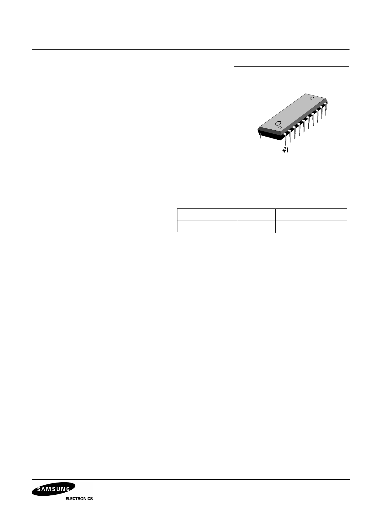
Device Package Operating Temperature
S1D2141X01-D0B0 20-DIP-300 -25 °C — +70 °C
FEATURES
• 3 - channel R/G/B Video Amplifier: 85MHz bandwidth.
20-DIP-300A
• DC contrast control range: -38dB (0V — 4V)
• DC sub contrast control range: -11dB (0V — 4V)
• Maximum Video output level: 7Vpp
• DC Brightness control range: 0V — 4V
• Include blank gate and clamp gate signal processing block
1
S1D2141X01 R/G/B VIDEO AMPLIFIER FOR MONITORS
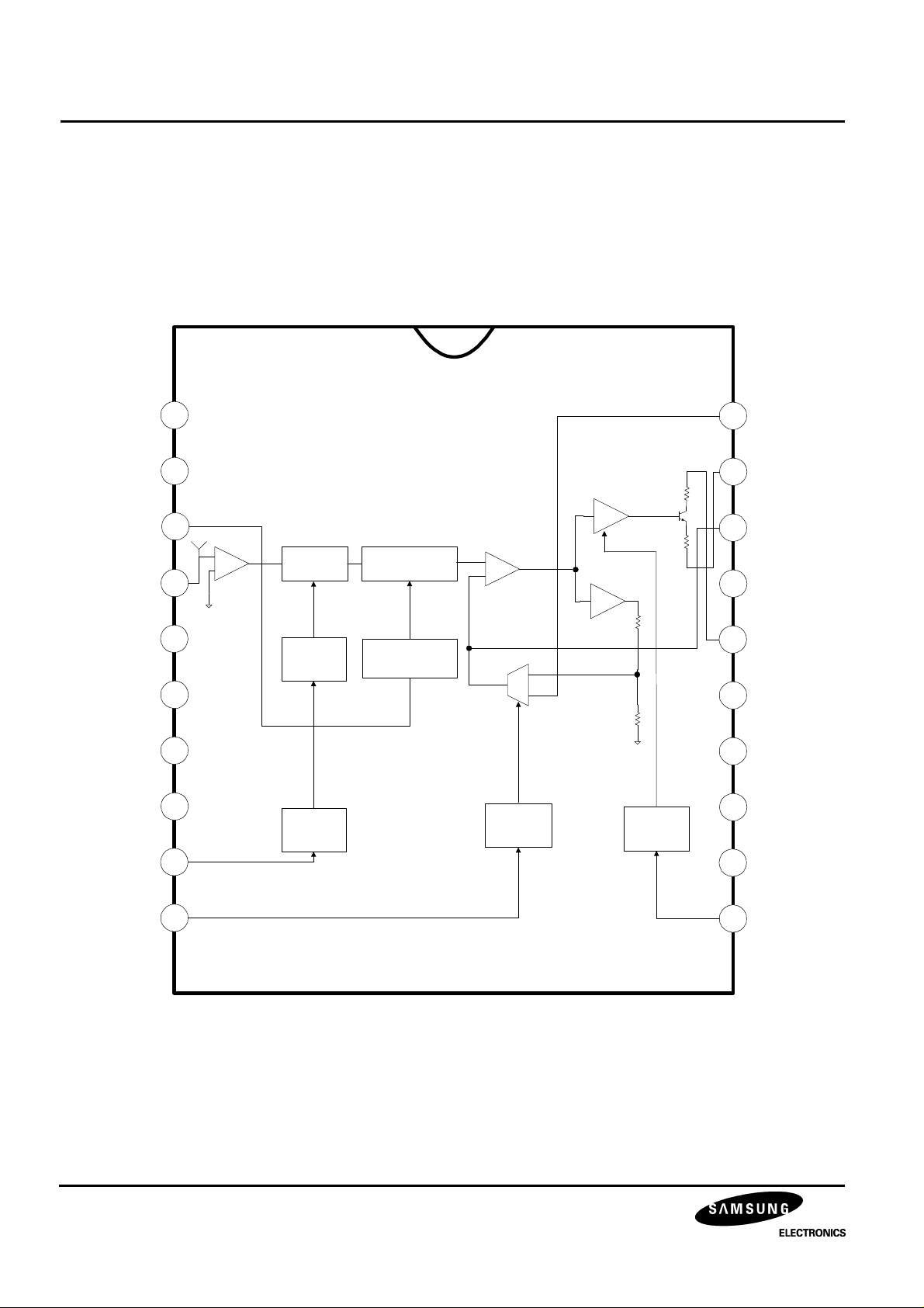
BLOCK DIAGRAM
ONE (RED)
OF THREE CHANNELS
BDRIVE
GDRIVE
RDRIVE
RIN
VCC1
GIN
GND1
BIN
CONST
1
2
3
2.4V
_
A1
+
4
5
6
VIDEO
CONTRAST
VIDEO
CONTRAST
CONTROL
VIDEO
SUB_CONTRAST
VIDEO
SUB_CONTRAST
CONTROL
+
A2
_
_
gm
+
-A3
-A4
7
8
CONTRAST
CONTROL
CLAMP
GATE
BLANK
GATE
9
20
19
18
17
16
15
14
13
12
BRIGHT
ROUT
RCLP
GOUT
VCC2
GCLP
GND2
BOUT
BCLP
CLP
10
2
11
BLK
R/G/B VIDEO AMPLIFIER FOR MONITORS S1D2141X01
PIN CONFIGURATIONS
Table 1. Pin Configurations
Pin No Symbol I/O Configurations
1 BDRIVE I Blue Gain Control
2 GDRIVE I Green Gain Control
3 RDRIVE I Red Gain Control
4 RIN I Red Video Input
5 V
CC1
- V
CC1
= 12V
6 GIN I Green Video Input
7 GND1 - Ground1
8 BIN I Blue Video Input
9 CONST I Contrast Control Input
10 CLP I Clamp Gate Pulse Input
11 BLK I Blank Gate Pulse Input
12 BCLP - Blue Clamp Capacitor
13 BOUT O Blue Video Output
14 GND2 - Ground2
15 GCLP - Green Clamp Capacitor
16 V
CC2
- V
CC2
= 12V
17 GOUT O Green Video Output
18 RCLP - Red Clamp Capacitor
19 ROUT O Red Video Output
20 BRIGHT I Brightness Control Input
3
S1D2141X01 R/G/B VIDEO AMPLIFIER FOR MONITORS
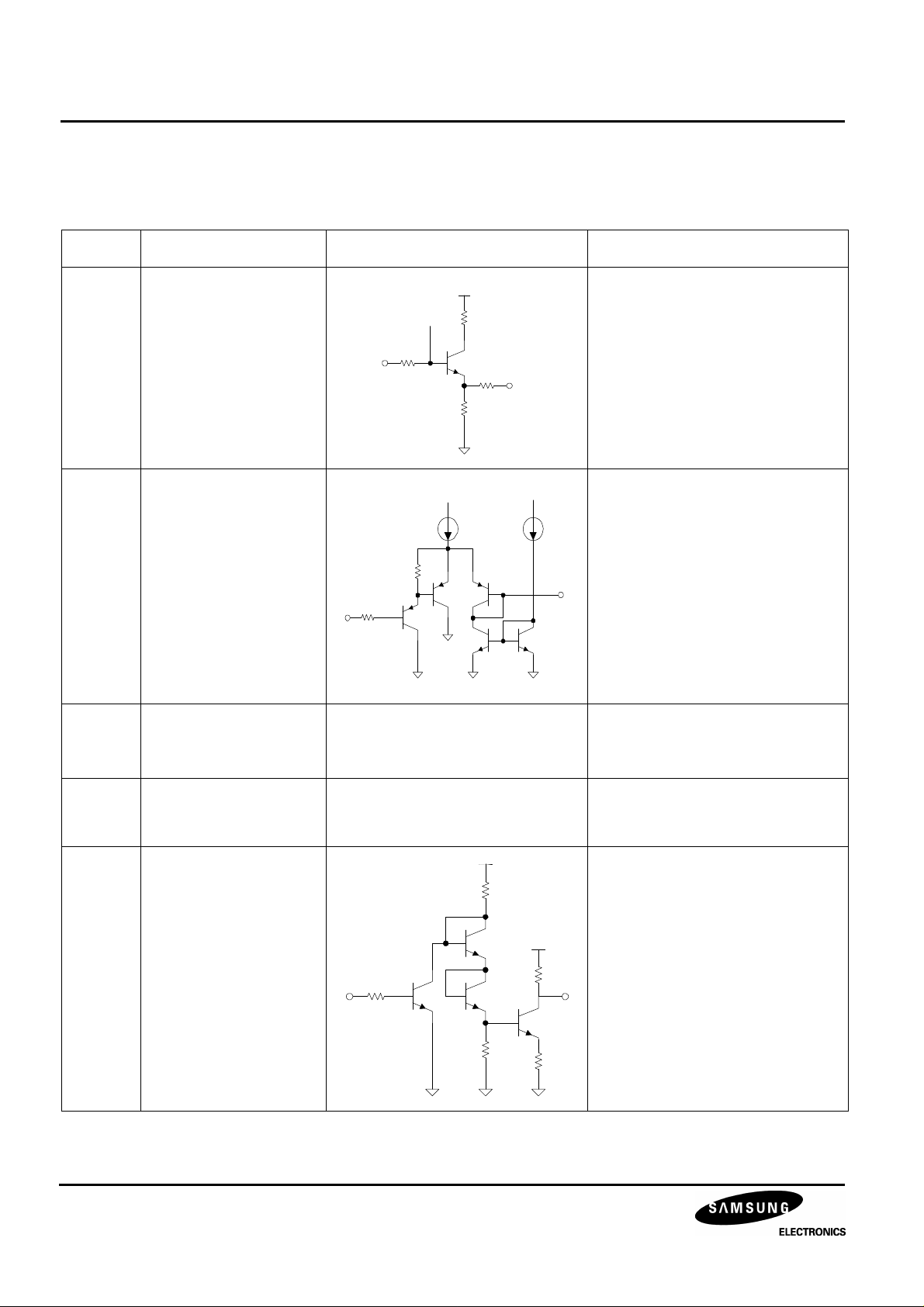
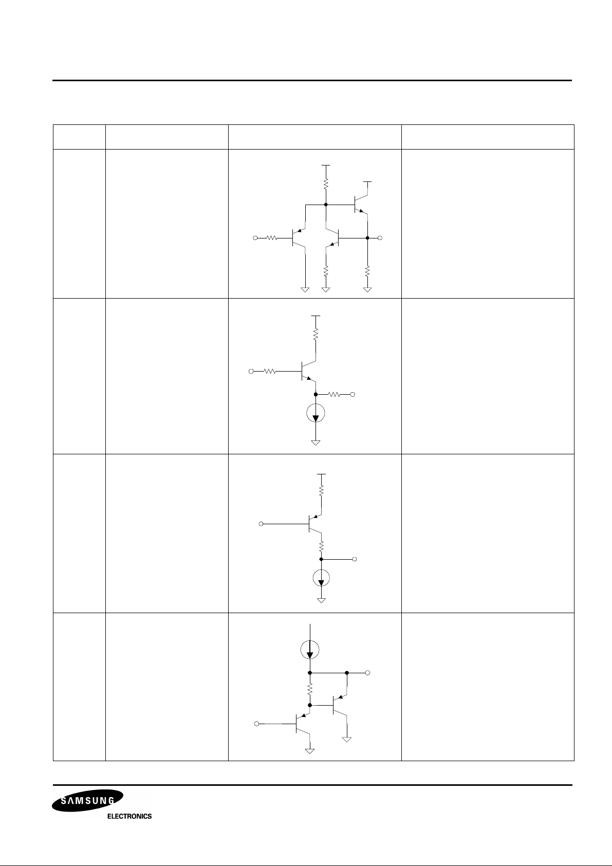
PIN DESCRITION
Table 2. Pin Description
Pin No Pin Name Schematic Description
4
6
8
9
1
2
3
5
17
Red Video Input
(RIN)
Green Video input
(GIN)
Blue Video Input
(BIN)
Video Contrast
(CONST)
Blue Drive
(BDRIVE)
Green Drive
(GDRIVE)
Red Drive
(RDRIVE)
V
CC1
V
CC2
VCC
Max input video signal is 0.7Vpp
2.4V Bias
Video maximum contrast control
range (0V ~ 4V) is -38dB
Sub contrast control range
(0V ~ 4V) is -11dB
PIN 9
- Supply voltage
7
14
GND1
GND2
10 Clamp Gate Input
(CLP)
PIN 10
4
- Ground
Video amp actives when clamp
gate signal is in low TTL level
R/G/B VIDEO AMPLIFIER FOR MONITORS S1D2141X01
Table 2. Pin Description (Continued)
Pin No Pin Name Schematic Description
11 Blank Gate Input
(BLK)
18
Red Video output
(ROUT)
16
Green Video output
(GOUT)
13
Blue Video output
(BOUT)
12
Blue Clamp Cap
(BCLP)
15
Green Clamp Cap
(GCLP)
19
Red Clamp Cap
(RCLP)
Video amp actives when blank
gate signal is in low TTL level
PIN 11
VCC
Video signal output
PIN 13
VCC
Brightness controlling actives by
charging and discharging of the
external cap (0.1uF)
20 Bright Control
(BRIGHT)
PIN 12
During the clamp gate period,
video signal's DC level
(clamp level) is fixed according
to the brightness control voltage
PIN 20
5
 Loading...