

Samsung RVMH060GDM0, RVMH100GAM0, RVMH080GAM0, RVMH060GBM0, RVMH100GCM0 Installation Manual
...
RUSSIAN
ENGLISH
INSTALLATION MANUAL
MANUAL DE INSTALACIÓN
MANUEL D’INSTALLATION
MANUALE D’INSTALLZIONE
MANUAL DE INSTALAÇÃO
INSTALLATIONS-HANDBUCH
E°XEIPI¢IO E°KATA™TA™H™
азлнкмдсаь ий млнДзйЗдЦ
System Air Conditioner
Aire acondicionado sistemático
Climatiseur numérique multifonctionnel
Sistema Aria Condizionata
Sistema Ar Condicionado
Klimaanlage System
™‡ЫЩЛМ· ∫ПИМ·ЩИЫМФ‡
лЛТЪВПМ˚И ЗУБ‰Ы¯М˚И дУМ‰ЛˆЛУМВ
ESPAÑOL
FRANÇAIS
ITALIANO
PORTUGUÊS
DEUTSCH
E S F I P D G R DB98-05168A(2)
E§§HNIKA
RVMH050CBM0
RVMH060GBM0
RVMH060GDM0
RVMH080GAM0
RVMH100GAM0
RVMH100GCM0
RVMH100F AM0
Heat pump
RVMC035EBM0
RVMC050CBM0
RVMC060GAM0
RVMC060GAM1
RVMC070F AM0
RVMC100GAM0
RVMC100F AM0
Cooling only
■ Parts List . . . . . . . . . . . . . . . . . . . . . . . . . . . . . . . . . . . . . . . . . . . 33
OO
OO
PPPPTTTTIIIIOOOONNNNAAAALL
LL
AA
AA
CCCCCCCCEEEESSSSSSSSOOOORRRRIIIIEEEESS
SS
■ Preparation for Outdoor Unit Installation . . . . . . . . . . . . . . . . . . . . 4
■ Deciding on Where to Install the Outdoor Unit . . . . . . . . . . . . . . . . 5
■ Outdoor Unit Installation . . . . . . . . . . . . . . . . . . . . . . . . . . . . . . . . . 7
■ Connecting the Cable . . . . . . . . . . . . . . . . . . . . . . . . . . . . . . . . . . . 8
■ Piping and refnet joint selection . . . . . . . . . . . . . . . . . . . . . . . . . . 12
■ Connecting the Refrigerant Pipe . . . . . . . . . . . . . . . . . . . . . . . . . 16
■ Performing Leak Test & Vacuum Drying . . . . . . . . . . . . . . . . . . . 17
■ Insulation . . . . . . . . . . . . . . . . . . . . . . . . . . . . . . . . . . . . . . . . . . . 19
■ Adding Refrigerant . . . . . . . . . . . . . . . . . . . . . . . . . . . . . . . . . . . . 20
■ Checking Correct Grounding . . . . . . . . . . . . . . . . . . . . . . . . . . . . 24
■ Setting Up Option Switches . . . . . . . . . . . . . . . . . . . . . . . . . . . . . 25
■ Functions of KEY on the Outdoor Unit PCB . . . . . . . . . . . . . . . . 26
■ Checking and Testing Operations . . . . . . . . . . . . . . . . . . . . . . . . 28
■ Troubleshooting . . . . . . . . . . . . . . . . . . . . . . . . . . . . . . . . . . . . . . 30
OO
OO
UUUUTTTTDDDDOOOOOOOORR
RR
UU
UU
NNNNIIIITT
TT
II
II
NNNNSSSSTTTTAAAALLLLLLLLAAAATTTTIIIIOOOONN
NN
Chapter
Chapter
Contents
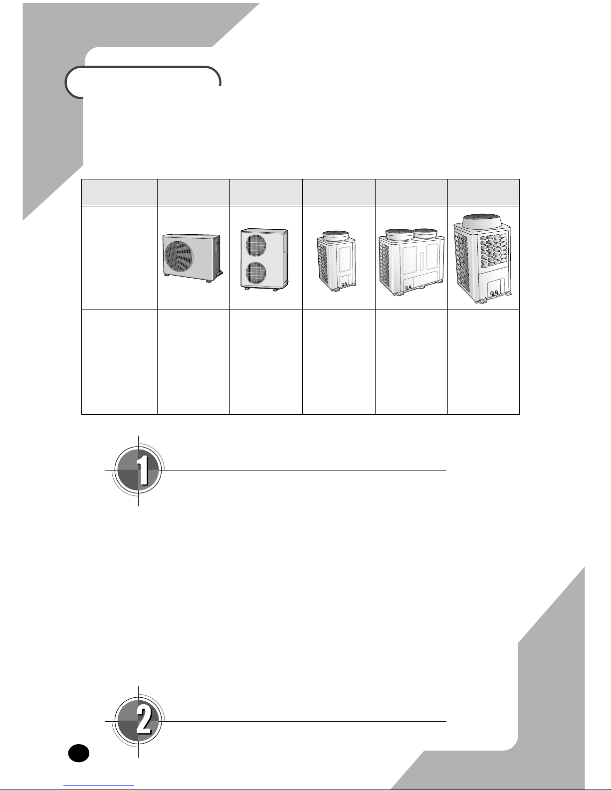
Type of outdoor
unit
ABCDE
Design
Model
RVMC035EBM0
B-1
RVMC050CBM0
RVMH050CBM0
B-2
RVMH060GBM0
RVMH060GDM0
RVMC060GAM0
RVMC060GAM1
RVMC070FAM0
RVMH080GAM0
RVMH100GAM0
RVMH100GCM0
RVMH100FAM0
RVMC100GAM0
RVMC100FAM0
E-2
E-3
■ Preparation for Outdoor Unit Installation . . . . . . . . . . 4
■ Deciding on where to Install the Outdoor Unit . . . . . . 5
■ Outdoor Unit Installation . . . . . . . . . . . . . . . . . . . . . . . 7
■ Connecting the Cable . . . . . . . . . . . . . . . . . . . . . . . . . 8
■ Piping and refnet joint selection . . . . . . . . . . . . . . . . 12
■ Connecting the Refrigerant Pipe . . . . . . . . . . . . . . . 16
■ Performing Leak Test & Vacuum Drying . . . . . . . . . . 17
■ Insulation . . . . . . . . . . . . . . . . . . . . . . . . . . . . . . . . . 19
■ Adding Refrigerant . . . . . . . . . . . . . . . . . . . . . . . . . . 20
■ Checking Correct Grounding . . . . . . . . . . . . . . . . . . 24
■ Setting Up Option Switches . . . . . . . . . . . . . . . . . . . 25
■ Functions of KEY on the Outdoor Unit PCB . . . . . . . 26
■ Checking and Testing Operations . . . . . . . . . . . . . . . 28
■ Troubleshooting . . . . . . . . . . . . . . . . . . . . . . . . . . . . 30
OO
OO
UUUUTTTTDDDDOOOOOOOORR
RR
UU
UU
NNNNIIIITT
TT
II
II
NNNNSSSSTTTTAAAALLLLLLLLAAAATTTTIIIIOOOONN
NN
ENGLISH
Chapter
E-4
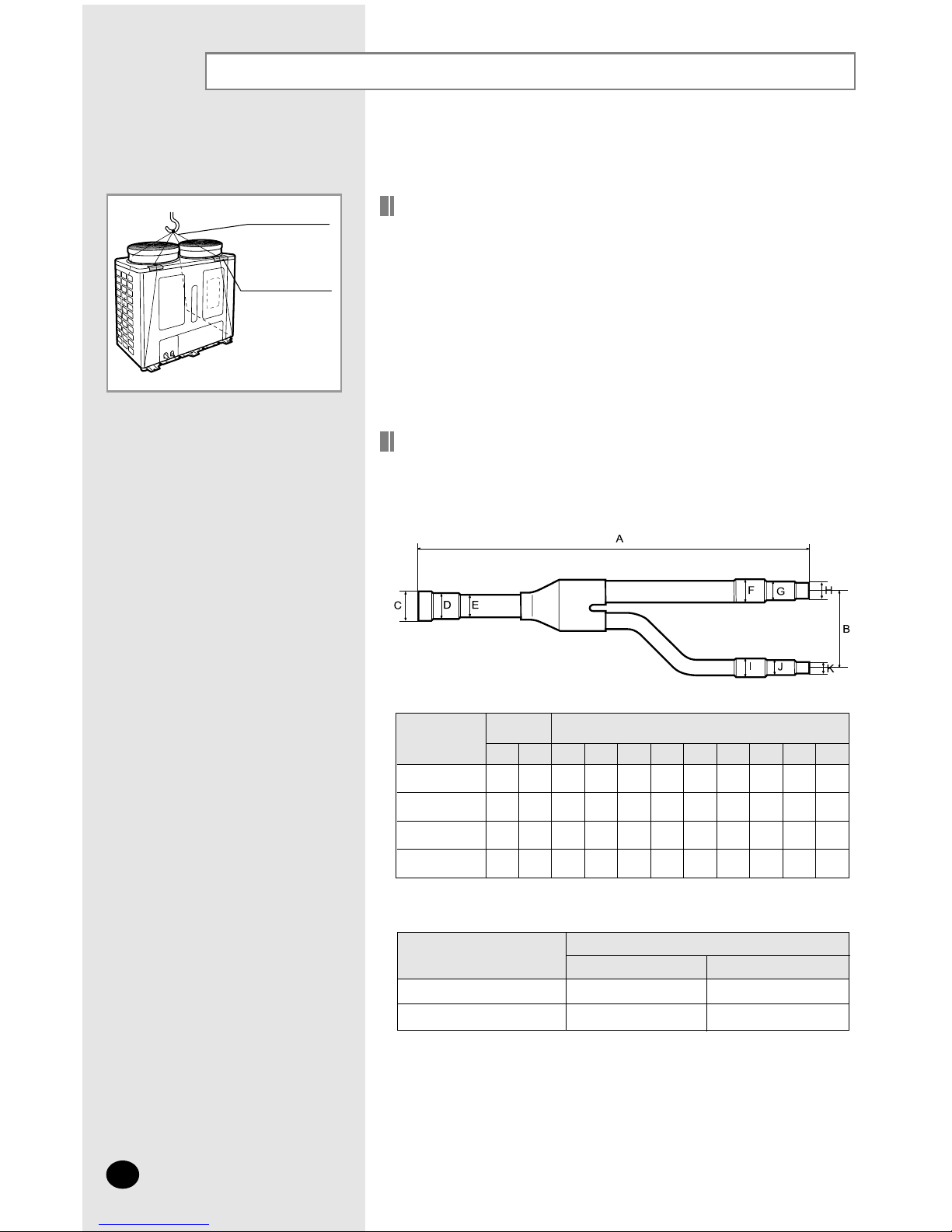
Moving the Outdoor Unit by Wire Rope
Fasten the outdoor unit by two 8m or longer wire ropes as
shown at the figure. To protect damage or scratches, insert
a piece of cloth between the outdoor unit and rope, then
move the unit.
Plate protection cloth
Wire rope
Preparation for Outdoor Unit Installation
How to choose Refnet Joint
A user must purchase a refnet joint to connect the indoor unit to the outdoor
unit.
◆
Choose the first refnet joint depending on the table below.
MXJ-0906A
MXJ-1206A
MXJ-2212A
MXJ-3112A
ABCDEFGHI JK
420
420
460
460
80
80
90
90
9.7
12.8
22.4
31.9
-
-
19.2
28.7
-
-
16.0
25.6
9.7
12.8
19.2
25.6
6.5
9.7
16.0
19.2
-
6.5
12.8
16.0
9.7
12.8
16.0
19.2
6.5
9.7
12.8
16.0
-
6.5
-
12.8
Refnet joint
Distance
(mm)
Inner diameter
(mm)
◆
Choose the others according to the total capacity of indoor units.
16000W or less
16000W or more
Total capacity of
indoor units
MXJ-0906A
MXJ-1206A
MXJ-2212A
MXJ-3112A
Refnet joint
Liquid Gas
Deciding on Where to Install the Outdoor Unit
E-5
ENGLISH
Outdoor Unit
◆ The outdoor unit must NEVER be placed on its side or upside down, as the
compressor lubrication oil will run into the cooling circuit and seriously
damage the unit.
◆ Choose a location that is dry and sunny, but not exposed to direct sunlight or
strong winds.
◆ Do not block any passageways or thoroughfares.
◆ Choose a location where the noise of the air conditioner when running and
the discharged air do not disturb any neighbours.
◆ Choose a position that enables the pipes and cables to be easily connected
to the indoor unit.
◆ Install the outdoor unit on a flat, stable surface that can support its weight
and does not generate any unnecessary noise and vibration.
◆ Position the outdoor unit so that the air flow is directed towards the open
area.
◆ Maintain sufficient clearance around the outdoor unit, especially from a radio,
computer, stereo system, etc.
◆ If the outdoor unit is installed at a height, ensure that its base is firmly fixed in
position.
◆ Make sure that the water dripping from the drain hose runs away correctly
and safely.
1.5m or more
Indoor Unit
Fuse
Outdoor
Unit
Remote Controller
1m or more
1m or more
1.5m or more
1.5m or more
1.5m or more
Fuse
Stereo
◆ You have just purchased a system air conditioner and it
has been installed by your installation specialist.
◆ This device must be installed according to the national
electrical rules.
CCCCAAAAUUUUTTTTIIIIOOOONN
NN
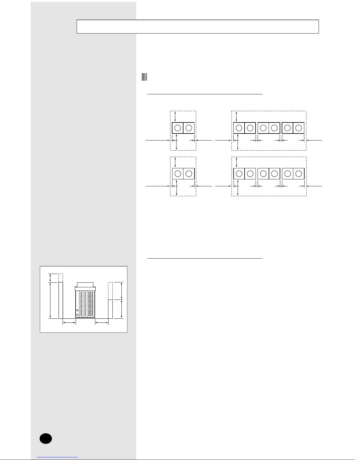
Deciding on Where to Install the Outdoor Unit (cont.)
E-6
If there is an obstacle around the outdoor unit...
◆ If an obstacle in front of the outdoor unit is higher than 1500mm, the half of
additional height should be added to the S1.
◆ If an obstacle behind the outdoor unit is higher than 500mm, the half of
additional height should be added to the S2.
❋ Max. height of obstacle
- Front side : 1500mm or less
- Air inlet side : 500mm or less
- Right/Left side : No limit
100 or more
100 or
more
300 or
more
Front
500
or more
Front
300 or
more
500 or
more
100 or
more
100 or
more
100 or
more
100 or
more
100 or more
100 or
more
300 or
more
Front
500
or more
Front
100 or
more
500 or
more
200 or
more
200 or
more
100 or
more
100 or
more
Unit : mm
Space Requirements for Outdoor Unit
If there is no obstacle around the outdoor unit...
S1 S2
Unit : mm
1500
h1
500
h2
Air inlet
Front
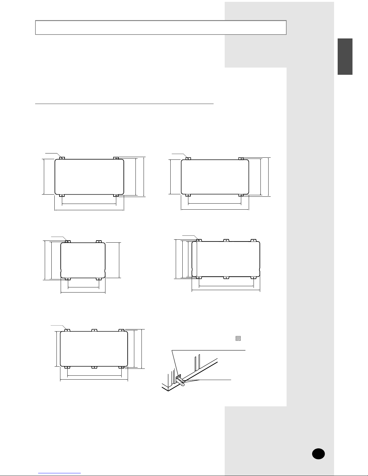
Outdoor Unit Installation
E-7
ENGLISH
Fix the outdoor unit with anchor bolts.
◆
The anchor bolt must be 20mm or higher from the base
surface.
NNNNoooottttee
ee
920
1157
667
637
597
Piping
Type D
Type B
Type A
To prevent the unit against a wild
animal or something, cover part
after connecting the pipe.
800
932
390
416
440
660
880
310
340
364
Anchor bolt hole
Type E
654
990
780
807
827
Anchor bolt hole
Anchor bolt hole
Anchor bolt hole
Type C
600
360
638
600
668
Anchor bolt hole
Unit : mm
The outdoor unit must be installed on a rigid and stable base to avoid
any increase in the noise level and vibration, particularly if the outdoor
unit is to be installed in a location exposed to strong winds or at a
height, the unit must be fixed to an appropriate support(wall or ground).
Outdoor Unit Installation (cont.)
E-8
◆ Make a drain outlet around the base for outdoor unit
drainage.
◆ If the outdoor unit is installed on the roof, you have to check
the ceiling strength and waterproof the unit.
CCCCAAAAUUUUTTTTIIIIOOOONN
NN
Outdoor Unit Support
20mm
Anchor bolt
Outdoor
Unit
➔
Outdoor Unit
Support
Base
Surface
➔
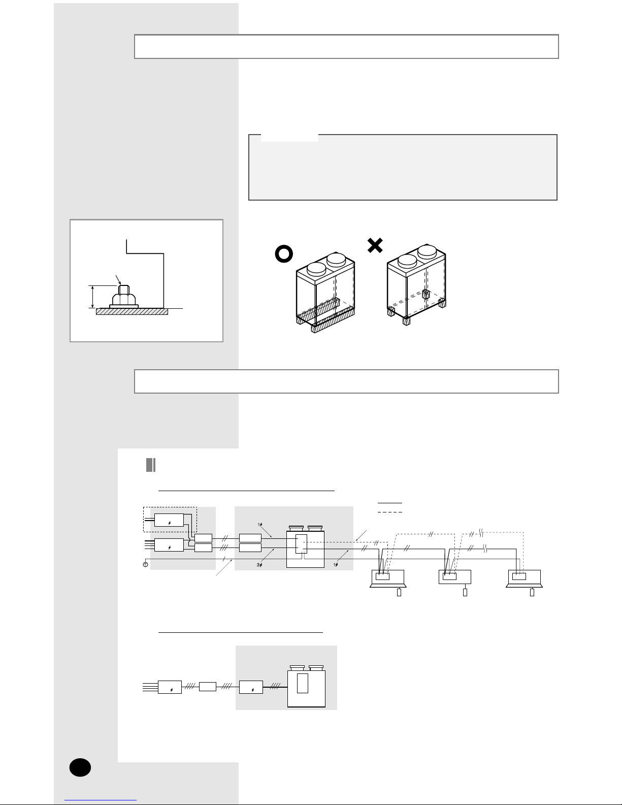
Connecting the Cable
Two electronic cables must be connected to the outdoor unit.
◆
The connection cord between indoor unit and outdoor units
◆
The power cable between outdoor unit and auxiliary circuit breaker.
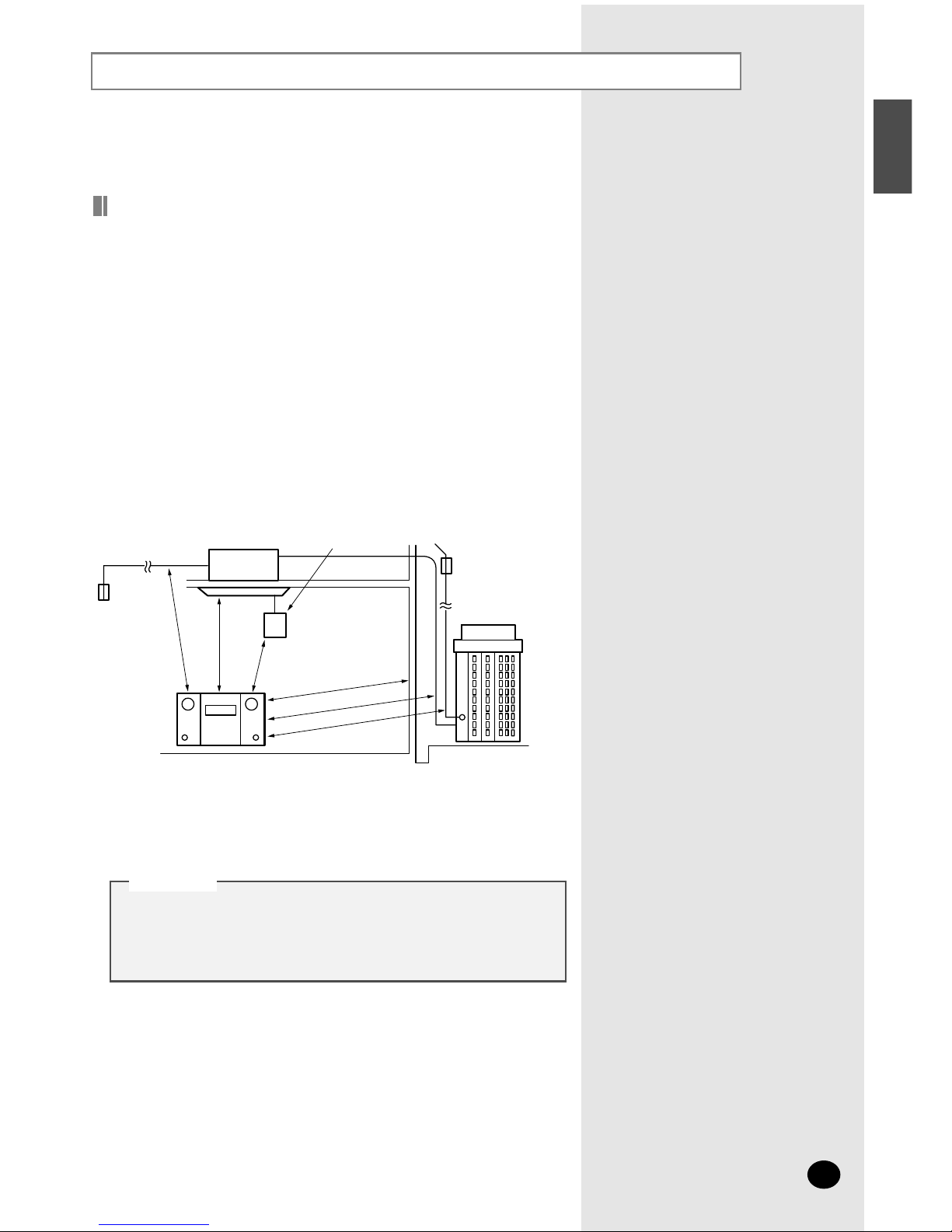
Example of Air Conditioner System
MCCB
3
MCCB
1
ELB
ELB
MCCB
MCCB
Outdoor Unit
Communication
Power cable
Communication
Indoor Unit
Earth
When using ELBs for 3 phase and 1 phase
MCCB
3
MCCB
3
ELB
Outdoor Unit
When using an ELB for 3 phase 4 wir
es
❋
If an outdoor unit is installed in a place in danger of an electric leak or submergence,
you must install the ELB.

Connecting the Cable (cont.)
E-9
ENGLISH
Power Cable Specification
❋
The power cable is not supplied with air conditioner.
IMPORTANT : All power supply cables/interconnection cables and communication cables must be type HOS-RN-F (at least).
Power Supply
3 Phase
Max/Min
(V)
MCCB ELB
Type of
outdoor
unit
Earth
Cable
Communication
Cable
Power
Supply
Power
Cable
Length Length
Power
Supply
Max/Min
(V)
-
208-
230V~
/60Hz
253/187
25A 25A
15A
15A
A
C
D
E
-----
-
3.5mm2,
CV ,
3Wires
-
220-
240V~
/50Hz
264/198
15A
15A
5.5mm2,
HOS-RN-F ,
3 Wires
30A
-
-
Frame:50A
Trip:30A
-
-
456/342
253/187
-
380-
415V~
/50Hz
208-
230V~
/60Hz
-
18m
or less
2.0mm2,
HOS-RN-F ,
2 Wires
2.0mm
2
,
HOS-RN-F ,
2 Wires
8.0mm2,
HOS-RN-F ,
3 Wires
18m~28m
15A
-
220-
240V~
/50Hz
264/198
15A
5.5mm2,
HOS-RN-F ,
3 Wires
20A
Frame:30A
Trip:20A
456/342
380-
415V~
/50Hz
18m
or less
8.0mm2,
HOS-RN-F ,
3 Wires
18m~28m
2.0mm2,
HOS-RN-F ,
2 Wires
2.0mm
2
,
HOS-RN-F ,
2 Wires
15A
-
-
220-
240V~
/50Hz
264/198
15A
5.5mm2,
HOS-RN-F ,
3 Wires
8.0mm2,
HOS-RN-F ,
3 Wires
30A
Frame:50A
Trip:30A
456/342
380-
415V~
/50Hz
18m
or less
8.0mm2,
HOS-RN-F ,
3 Wires
14.0mm2,
HOS-RN-F ,
3 Wires
18m~28m
208-
230V~
/60Hz
253/187
B
18m
or less
18m
or less
-
18m~28m
15A
15A
50A
Frame:75A
Trip:50A
253/187
208-
230V~
/60Hz
208-
230V~
/60Hz
253/187
18m
or less
18m~28m
14.0mm2,
HOS-RN-F ,
3 Wires
22.0mm
2
,
HOS-RN-F ,
3 Wires
20A
20A
75A
Frame:100A
Trip:75A
253/187
208-
230V~
/60Hz
208-
230V~
/60Hz
253/187
20m
or less
20m~50m
5.5mm2,
HOS-RN-F ,
3 Wires
8.0mm
2
,
HOS-RN-F ,
3 Wires
15A
15A
30A
Frame:50A
Trip:30A
418/342
308V
/60Hz
220V
/60Hz
242/198
18m
or less
18m~28m
8.0mm2,
HOS-RN-F ,
3 Wires
14.0mm
2
,
HOS-RN-F ,
3 Wires
20A
20A
50A
Frame:75A
Trip:50A
456/342
380-
415V~
/50Hz
220-
240V~
/50Hz
264/198
20m
or less
20m~50m
-
---
18m
or less
18m~28m
18m~28m
Ø
1.6mm,
HOS-RN-F ,
1 Wire
0.75~
1.25mm
2
HOS-RN-F ,
2 Wires
Power
Cable
MCCB ELB
Single Phase
Connecting the Cable (cont.)
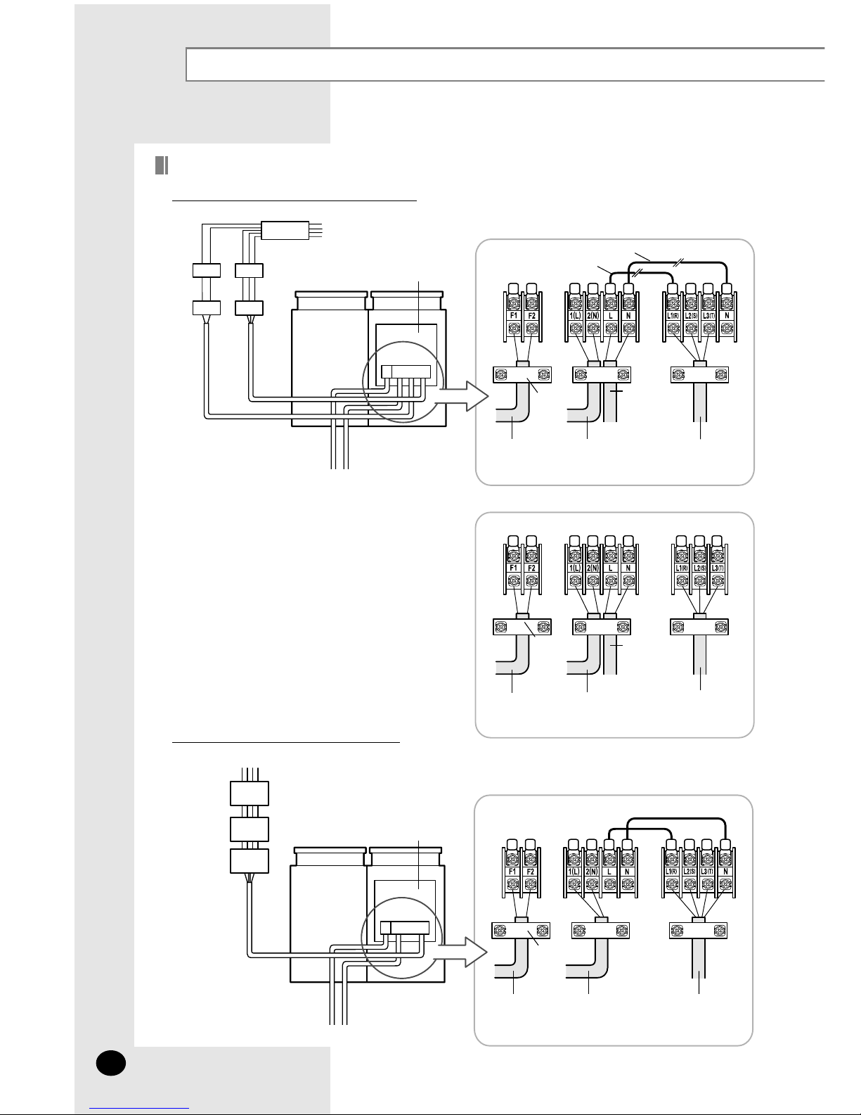
E-10
Wiring Diagram of Power Cable
When using ELBs for 3 phase and 1 phase
When using an ELB for 3 phase 4 wires
MCCB
ELB ELB
MCCB MCCB
Power Supply
Electrical component box
Indoor Unit
Communication
Cable
Single
Phase
3 Phase
3 Wires
Connection cord 3 Phase
Power Cable
Single
Phase
AC220V
Cable
clamp
Part A
Part B
MCCB
ELB
MCCB
Power Supply
Electrical component box
Indoor Unit
Communication
Cable
3 Phase
4 Wires
Connection cord 3 Phase
Power Cable
Cable
clamp
Cut off the part A and B
◆
Case 1
◆
Case 2
Communication
Cable
Connection cord
3 Phase
Power Cable
Single
Phase
AC220V
Cable
clamp

E-11
ENGLISH
Wiring Diagram of Connection Cord
Connection Cord Specifications
Indoor Unit 1
Outdoor Unit
Type AOutdoor unit
Indoor Unit 2 Indoor Unit 3
220V/60Hz
220-240V~/50Hz
208-230V~/60Hz
±10%
2.0mm
2
(HOS-RN-F,
2wires)
Ø1.6mm
(
HOS-RN-F
,
1wire)
0.75~
1.25mm
2
0.75~
1.25mm
2
Power Supply (Single Phase)
Earth Cable
Communication
Cable (HOS-
RN-F, 2wires)
Home server
(HOS-RN-F,
2wires)
Power Supply
Max/Min(V) Power Cable
◆ When connecting cables, make the cable pass through the
cable tube as shown at the figure.
◆ Must keep the cable in a protection tube.
◆ Keep distances of 50mm or more between power cable and
communication cable.
CCCCAAAAUUUUTTTTIIIIOOOONN
NN
Gas refrigerant pipe
Cable tube
Communication
cable
Connection cord
Power cable
Liquid refrigerant pipe
- Max. length of communication cable : 120m
- Whole length of cable : 240m
- Allowable branches : 10
 Loading...