

Samsung RVMC050CBM0, RVMC070FAM0, RVMH060GBM0, RVMC100FAM0, RVMC100GAM0 Technical Manual
...
SAMSUNG ELECTRONICS
SAMSUNGDV MTMAir Conditioner
SAMSUNG DVM Air Conditioner
Technical Manu al
Ι
Overview
1. DVM system series
1-1. What is DVM?
1-2. Features of DVM
6
7
2. DVM line-up
2-1. Numbering system of model
2-2. Combination
ΙΙ
Control system
12
18
1. Remote controller
1-1. Wireless remote controller
1-2. Wired remote controller
1-3. Centralized controller
1-4. Function controller
2
3
4
4
2. Receiver & display
unit (Duct type)
2-1. Concealed type
2-2. Standard type
5
6
3. Interface module
4. Installation
4-1. Wireless remote controller
4-2. Wired remote controller
4-3. Centralized controller
4-4. Function controller
4-5.
Receiver & display unit - concealed type
4-6.
Receiver & display unit - standard type
4-7. Interface module
8
9
12
17
19
20
21
5. Assigning address
5-1. Indoor unit
5-2. Outdoor unit
6.
Indoor unit PCB option code
6-1. PCB option code input method
6-2. Option code
23
24
25
30
7. S-Net
8.
Indoor unit PCB option code
Building management system
9.
ΙΙΙ
Indoor unit
1. Features
1-1. 1-way cassette type
1-2. 4-way cassette type
1-3. Duct type
1-4. Wall-mounted type
1-5. Floor standing type
1-6. Ceiling type
2. Specification
2-1. 1-way cassette type
2-2. 4-way cassette type
2-3. Duct type (Low silhouette)
2-4. Duct type (Built-in)
2-5. Duct type (High pressure)
2-6. Wall-mounted type
2-7. Floor standing type
2-8. Ceiling type
3. Functional parts and
safety devices
3-1. 1-way cassette type
3-2. 4-way cassette type
3-3. Duct type (Low silhouette)
3-4. Duct type (Built-in)
3-5. Duct type (High pressure)
3-6. Wall-mounted type
3-7. Floor standing type
3-8. Ceiling type
4. Capacity table
4-1. 50Hz
4-2. 60Hz
5. Dimension
5-1. 1-way cassette type
5-2. 4-way cassette type
5-3. Duct type (Low silhouette)
5-4. Duct type (Built-in)
5-5. Duct type (High pressure)
5-6. Wall-mounted type
5-7. Floor standing type
5-8. Ceiling type
5-9. Wireless remote controller /
Receiver & display unit
5-10. Wired remote controller
5-11. Centralized controller
5-12. Function controller
5-13.
Electronic expansion valve
kit (Distributor kit type)
6.
Refrigerant system diagram
2
4
6
8
10
12
14
16
18
20
24
26
30
32
(Cooling only & heat pump)
6-1.
Refrigerant system diagram
6-2. Main parts status
7.
Electric circuit diagram
7-1. 1-way cassette type
7-2. 4-way cassette type
7-3. Duct type
7-4. Wall-mounted type
7-5. Floor standing type
7-6. Ceiling type
8. Noise level
8. Noise level
8-1. Overall
8-2. Octave band level
9.
Velocity of air flow &
temperature distribution
9-1. 1-way cassette type
34
9-2. 4-way cassette type
34
9-3. Wall-mounted type
35
9-4. Ceiling type
36
36
10. Fan specifications
37
38
10-1.
Duct type(Low silhouette)
38
10-2.
Duct type(Built-in)
10-3.
Duct type(High pressure)
11. Panel
39
45
11-1. 1-way cassette type
11-2. 4-way cassette type
12. Electronic expansion
51
52
54
55
57
58
60
61
62
70
71
71
72
valve kit
12-1. Built-in type
12-2. Distributor kit type
13. Options
73
73
74
76
78
80
82
84
86
87
102
103
105
107
108
108
110
111
112
113
113
ΙΛ Λ
Outdoor unit
1. Unit selection
(with cooling load)
2. Specification
2-1. 50Hz
2-2. 60Hz
3. Functional parts and
safety devices
4. Capacity table
4-1. 50Hz
4-2. 60Hz
5. Dimension
5-1. Upward (2-FAN)
5-2. Onward
5-3. Upward (1-FAN)
5-4. Upward (Super cooler)
6.
Refrigerant system diagram
6-1. Cooling only
6-2. Heat pump
7.
Electric circuit diagram
7-1. Cooling only
7-2. Heat pump
8.
Consideration for
outdoor unit selection
Change of capacity depending
8-1.
on refrigerant piping length
Condition of operating
8-2.
restriction
9. Noise level
4
6
13
19
29
30
31
32
33
36
40
44
47
49
Installation
1. Product
1-1. Preparation for installation
1-2. Deciding on where to install
the air conditioner
1-3. Space requirements for the
air conditioner
1-4. Accessories
1-5. Installation
2. Panel
2-1. 1-way cassette type
2-2. 4-way cassette type
2-3. Duct type (Built-in)
3.
Connecting the indoor
unit refrigerant pipe
4.
Drain hose installation
5.
Drain pump installation
5-1. Accessories
5-2. Installation
6. Electronic expansion
valve kit
6-1. Built-in type
6-2. Distributor kit type
7. Wiring
Overall system configuration
7-1.
Cable specification for outdoor unit
7-2.
Connection cord specification
7-3.
Wiring diagram
7-4.
Connection cord wiring diagram
7-5.
Power wiring and communication
7-6.
wiring configuration
Communication cable connection
7-7.
15
17
18
24
24
25
26
30
31
32
32
33
33
34
8. Piping and refnet
2
3
4
10
13
joint selection
8-1. Examples of using only
Refnet joint
8-2.
Examples of using both Refnet
joint and distributor kit
8-3. Limitation when piping is
installed by using only
Refnet joint
8-4. Requirement when piping is
installed using simultaneously both refnet joint and
contributor kit
8-5. Pipe selection
8-6. Refnet joint selection
8-7. Installation of piping filter
9. Charge/recovery of
refrigerant
9-1. Refrigerant charging
9-2.
Additional refrigerant amount
calculation method
9-3. Recovery of refrigerant
10. Testing operation
11. Cautions for
refrigerant leaks
41
41
42
43
44
46
46
47
48
49
10. Options
Overview
Ι
1. DVM system series
1-1. What is DVM?
1-2. Features of DVM
2.
DVM line-up
2-1. Numbering system of model
2-2. Combination
6
7
12
18
Ι
. Overview
1. DVM system series
1-1. What is DVM?
The DVM(Digital Variable Multi) air conditioning system is operated by a variable-capacity compressor
and is accommodated by multiple evaporators (indoor units). It is touted as the next-generation modular
system in the world of high-efficiency air conditioning. lt has undoubtedly changed the face of cooling
associated with high-storied buildings. It provides a broad range of different applications for settings such
as offices, hotels and schools. With its easy installation and simple controlling system, the DVM will more
than meet the demands of the air conditioning market.
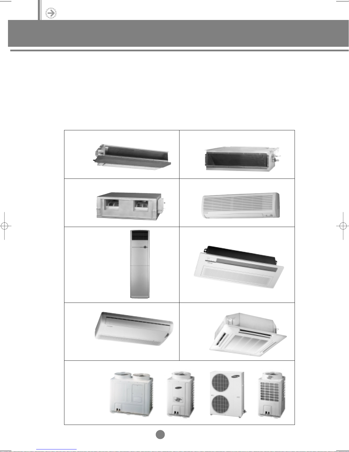
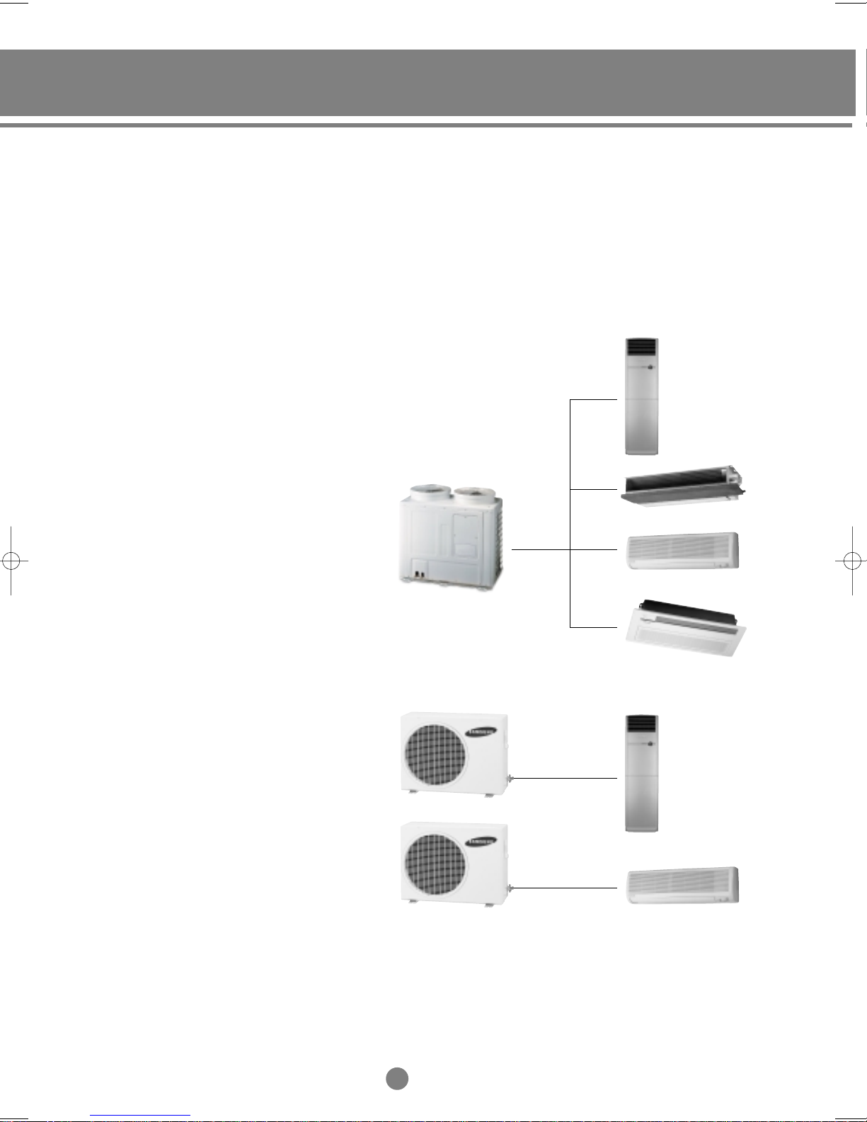
Duct type (Low silhouette) Duct type (Built-in)
Duct type (High pressure) Wall-mounted type
Floor standing type 1-way cassette type
Ceiling type
4-way cassette type
Outdoor unit
6
I
1-2. Features of DVM
(1) Customized air conditioner
1) Up to 16 indoor units can be connected to one outdoor unit.
2) Indoor units can be combined by various methods, according to each room’s use and shape.
3) There are several indoor units which can be applied; 1-way cassette type, 4-way cassette type,
Ceiling, Duct (Low silhouette, Built-in, High pressure), Wall-mounted and Floor standing type.
(2) Comparison of DVM with conventional air conditioners
1) DVM air conditioner
Variable capacity (Energy Saving)
①
Competitive price (Compared with the Inverter type)
②
Can be installed in houses / commercial buildings
③
Versatile combination of indoor units
④
Various remote controls
⑤
2) Conventional air conditioners
Fixed capacity
①
Unfavorable in case of installing more than 3 units / system
②
7
I
Ι
. Overview
1. DVM system series
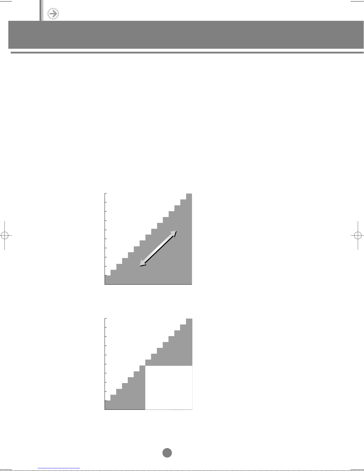
(3) Variable compressor
The world’s first PWM(Pulse Width Modulation) compressor controls the cooling & heating capacity
automatically, depending on the load.
1) Principle of the digital compressor
Composition
①
The solenoid valve is installed for the compressor´s loading / unloading between the upper part of the
fixed scroll and the suction pipe.
Mechanism
②
a. When the solenoid valve is turned off, the fixed scroll is closed to the orbiting scroll (Loading),
b. When the solenoid valve is turned on, the fixed scroll is separated from the orbiting scroll (Unloading),
c. This process controls the On / Off times of the valve and the rotating refrigerants in the circle,
thus adjusting the capacity.
d. The cooling capacity of the outdoor unit is controlled automatically,depending on the
number of operating indoor unit(s).
< 1-Compressor system >
100
90
80
70
60
50
40
30
20
Running ratio of compressor(%)
10
0
3000 6000 9000 12000 15000 18000
unloading
Total capacity of operating indoor unit(s)
(kcal/h)
loading
< 2-Compressor system >
100
90
80
70
60
50
40
30
20
Running ratio of compressor(%)
Digital only
10
operating
0
0 5000 10000 15000 20000 25000
Total capacity of operating indoor unit(s)
Digital operating
Fixed compressor
operating
(kcal/h)
8
I
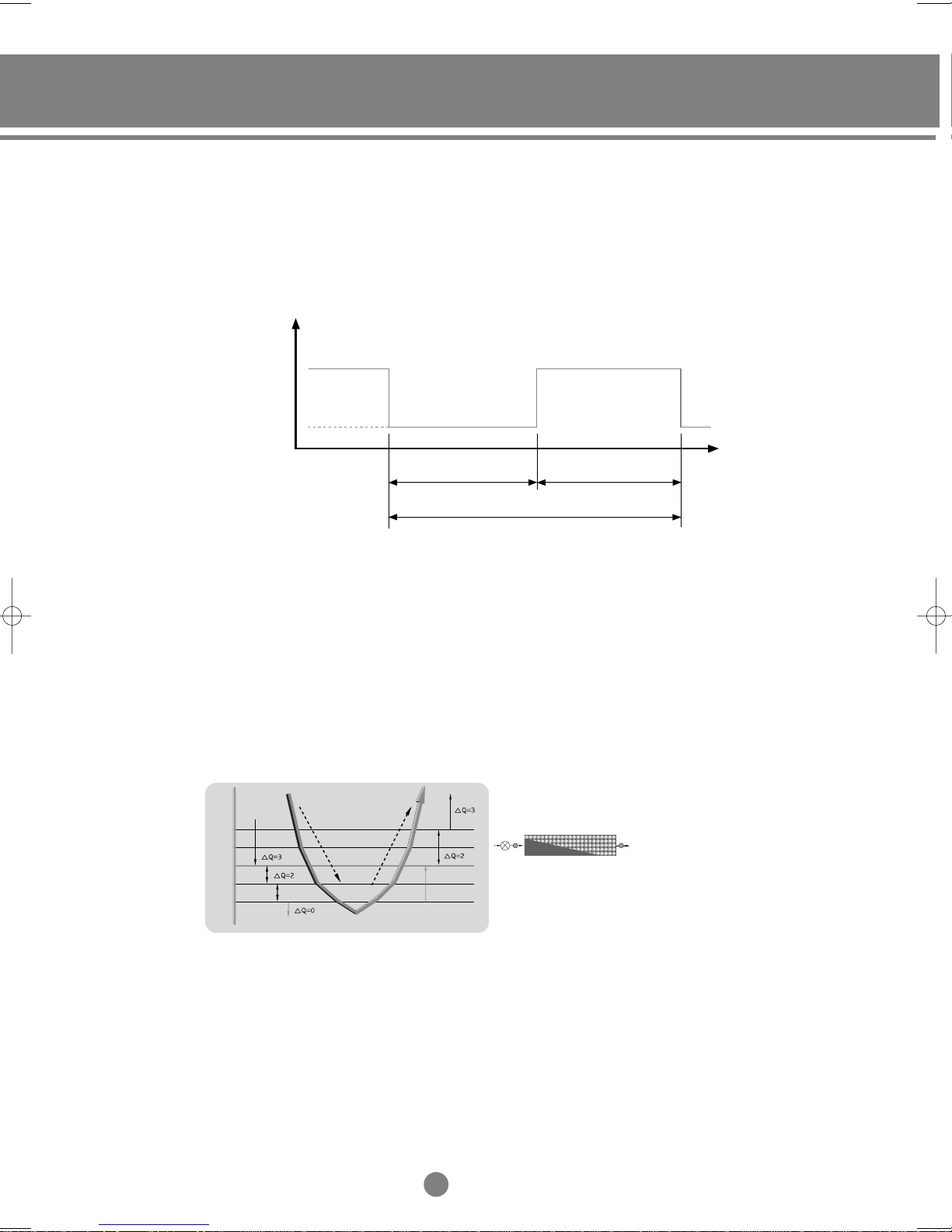
2) PWM (Pulse Width Modulation) valve
PWM valve is the valve to take away the fixed scroll by lifting up through the difference of pressure after the digital
scroll compress being connected to the outlet and inlet of suction. Therefore, the capacity of compressor is controlled
automatically according to the operation status such as loading when the valve is closed or unloading when the valve
is opened. PWM means the control of ON/OFF signal to the valve for loading/unloading.
Relationship between PWM valve and loading/unloading
compression
PWM valve open PWM valve close
non-compression
(rotating in vain)
Unloading
Period (Cycle Time, T)
Loading
(4) Refrigerant flow rates control
Refrigerant flow rates through the electronic expansion valve are controlled by the 2 factors which are the
temperature difference between inlet and outlet of evaporator and the difference between room and set temperature.
a. An electronic expansion valve optimally distributes refrigerant flow rates to each room and the fuzzy logic enables
comfortable cooling more precisely; refer to the figure below.
b. The air conditioner senses the temperature difference between inlet and outlet of evaporator, plus the temperature
difference between room and set temperature. And it calculates the superheat and the room temperature status,
then adjusts refrigerant flow rates after deciding the opening steps of valve.
①②
1
0.5
0
Falling room temperature
-0.5
-1
④
③
①
Rising room temperature
②
Open electronic expansion valve
③
Closed electronic expansion valve
④
9
I

Ι
. Overview
1. DVM system series
(5) Long & single piping system
1) Piping can be extended up to 100 meters; refer to the figure.
2) The outdoor unit is connected with each indoor unit by
single refrigerant piping.
(6) Convenient centralized control
50m (8.0~10.0HP), 30m (7.5HP ) (Height between indoor and outdoor unit)
70m(2.5HP), 100m(3.5HP~10.0HP) (Max. piping length)
1) Every indoor unit has its own remote controller.
In addition, a maximum of 16 indoor units
can be controlled with the centralized controller.
2) A maximum of 256 indoor units can be controlled
by using the PC Control.
(7) Easy installation
Simple planning and installation during the early
stage of building construction or renovation.
(8) Minimizing operation costs
The cooling / heating capacity is adjusted automatically
with the variable compressor, which reduces power
consumption and running costs.
Equipment
Initial cost (US$)
Running cost
(US$)
Piping
Duct-install
Grand
Power consumption
Monthly consumption
Annual consumption
(6 months in a year)
1 year rate
3 year rate
5 year rate
Comparison
44.2kW X 0.8
(Variable Compressor)
DVMDivision
29,812
2
17/m
39,812
12,906kWh
77,436kWh
5,575
16,726
27,877
100%
Chiller Unitary
25,558
5,111
2
17/m
40,670
43kW X 1.0
15,695kWh
94,170kWh
6,780
20,340
33,900
121%
→
27,500
37,500
52.5kW X 1.0
19,162kWh
114,972kWh
24,833
41,389
15m (Height between indoor units)
➞
2
17/m
8,277
148%
→
❋ The results are based on Samsung Lab., therefore there may be differences according to the condition of
installation and the environment of the use.
❋ Heat loads : 90,000 kcal/h in Korea
❋ Total area : 750m
❋ Running : 3 months in every summer and winter
2
10
I
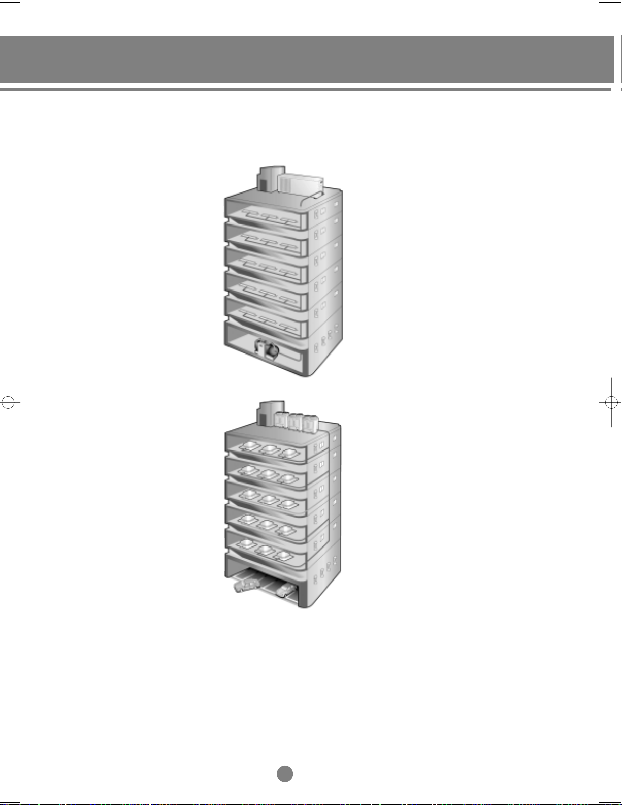
(9) Space Saving
The outdoor units connected with several indoor units do not require much space.
1) Conventional System
2) DVM System
11
I
Ι
. Overview
2. DVM line-up
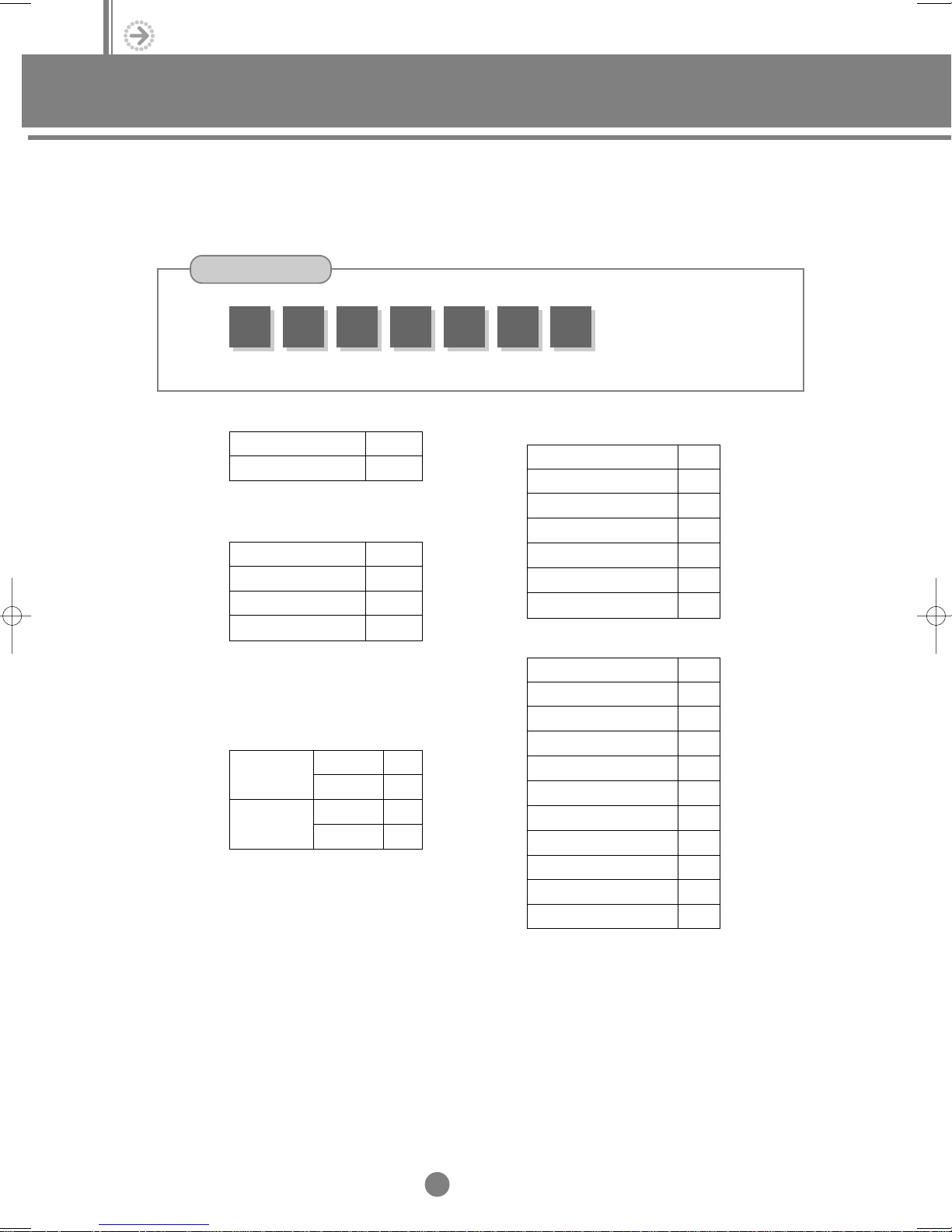
2-1. Numbering system of model
(1) Indoor unit and outdoor unit (Conventional model)
Model
A
DM
①
Semi-finished product
①
Indoor unit
Outdoor unit
Classification of product
②
1-way cassette type
4-way cassette type
Duct type
Outdoor unit
Capacity (Btu x 100)
③
Option
④
Indoor unit
Outdoor unit
Function
version
Recipro
PWM
-
180 0
③②
A
M
KM
BM
DM
UF
0
1
0
1
④
A
⑤
0
⑥
Power supply
⑤
- Indoor unit
115V, 60Hz
220V, 60Hz
208~230V, 60Hz
200~220V, 50Hz
220~240V, 50Hz
127V, 50Hz
220~240V, 50/60Hz, 1ø
- Outdoor unit
115V, 60Hz
220V, 60Hz
208~230V, 60Hz
200~220V, 50Hz
220~240V, 50Hz
220V, 60Hz, 3ø
380~415V, 50Hz, 3ø
127V, 50Hz
220~240V, 50/60Hz, 1ø
380V, 60Hz, 3ø
460V, 60Hz, 3ø
A
B
C
D
E
M
N
A
B
C
D
E
F
G
M
N
H
J
Version
⑥
12
I
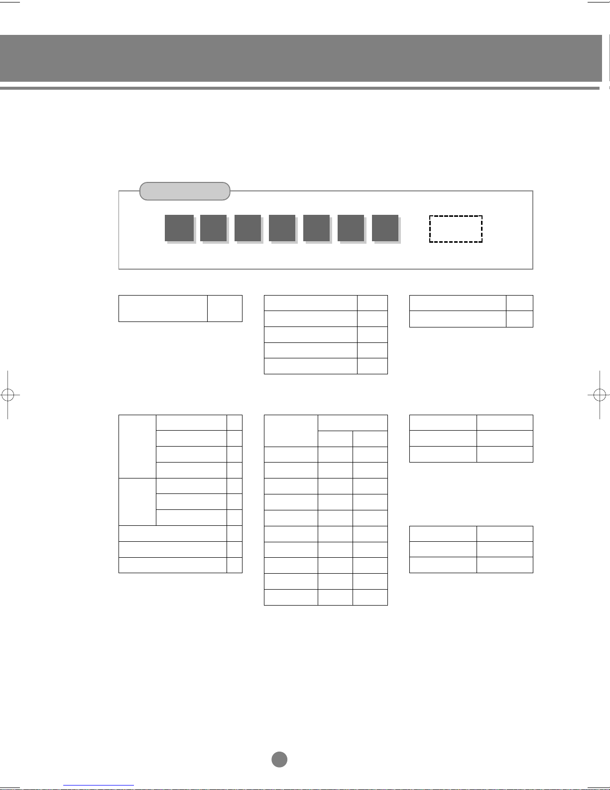
(2) Indoor unit and outdoor unit (New Model)
1) Indoor unit
Model
AVM①K
Semi-finished product
①
Variable capacity free
joint multi (DVM)
Classification of product
②
1-way
Cassette
type
Duct type
Floor standing type (PAC)
4-way
2-way
Exposed
Low silhouette
High pressure
Built-in
Wall-mounted type
Ceiling type
②
AVM
W
H
100
③
K
C
G
N
D
H
B
F
P
④
Mode
③
Cooling only (C/O)
Heat pump (H/P)
C/O+Hot water heater
Capacity (x 1/10 kW, 3 digits)
④
Btu/h
B
⑤
H/P+Heater
C/O+Heater
7K
9K
12K
18K
20K
24K
28K
36K
44K
48K
Watt
50Hz
2000W
2600W
3500W
5200W
6000W
7000W
8200W
10500W
12800W
14000W
A
⑥
10500W
12800W
14000W
C
H
E
G
N
60Hz
2000W
3200W
4000W
5200W
6000W
7200W
8300W
0
⑦
0 0 0
Power supply
⑤
208~230V, 60Hz
220~240V, 50Hz
Refrigerant
⑥
R22
R407C
R410A
Version
⑦
~
~
C
E
A
B
C
0
1
2
13
I
Ι
. Overview
2. DVM line-up
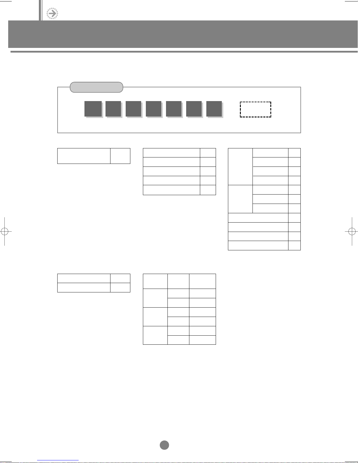
2) Outdoor unit
Model
RVM①H
②
Semi-finished product
①
Variable capacity free
joint multi (DVM)
Mode
②
Cooling only (C/O)
Heat pump (H/P)
Capacity (x 1/10 HP, 3 digits)
③
RVM
C
H
060
③
B
④
Power supply
④
208~230V, 60Hz, 3ø
380~415V, 50Hz, 3ø
Refrigerant / Discharge direction
⑤
Refrigerant
R22
R407C
R410A
A
⑤
208~230V, 60Hz
380V, 60Hz, 3ø
460V, 60Hz, 3ø
Discharge
direction
Upward
Onward
Upward
Onward
Upward
Onward
A
⑥
C
F
G
H
J
Classification
A
B
C
D
E
F
⑦
0
⑥
Duct type
⑦
0 0 0
Combination of indoor unit
1-way
Cassette
type
Floor standing type (PAC)
Version
4-way
2-way
Exposed
Low silhouette
High pressure
Built-in
Wall-mounted type
Ceiling type
Free
K
C
G
N
D
H
B
W
F
P
M
14
I

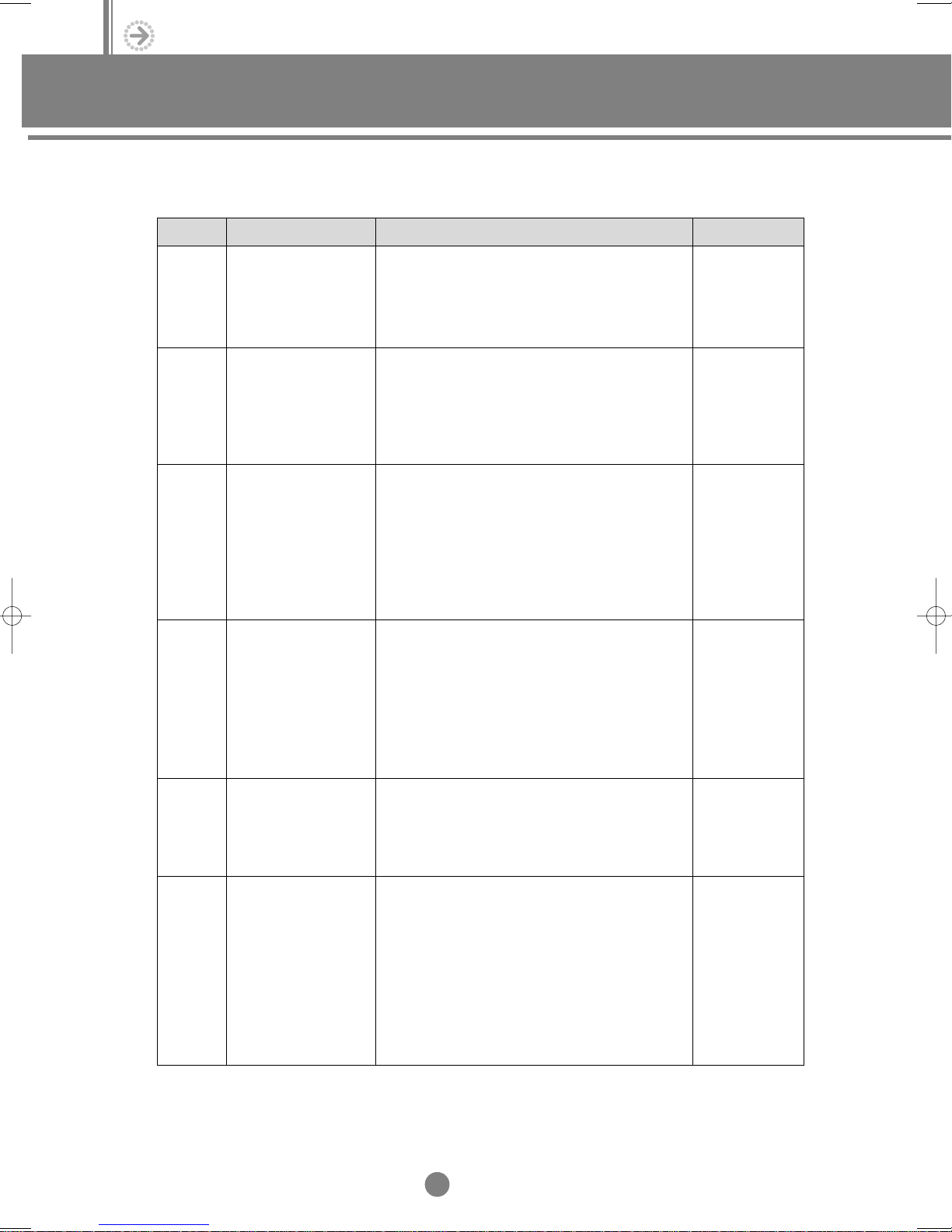
(3) Options
Parts Model Example
Electronic
expansion
valve kit
(Attachment
type)
Electronic
expansion
valve kit
(
Distributor
kit type)
Discharge
duct
Refnet kit ● MXJ-1509B
MEV- ①②③
MXD- ①②③④⑤
MDF- ①②
MXJ- ①②③
MEV : Optional electronic expansion valve
: Electronic expansion valve model (2 digits)
①
: Manufacturer
②
: Version
③
MXD : Optional distributor kit
: Max diameter (2 digits)
①
: Kinds (marked as K2 for two kinds)
②
: Minimum diameter
③
(Marked as 00 only for use of one kind and marked
with minimum diameter for use of two kinds)
: Kinds (marked as K2 for two kinds)
④
: Version
⑤
MDF : Optional distributor duct flange
: Hole size(ø, cm, 2 digits)
①
: Version
②
MXJ : Optional refnet (Y-joint) kit
: Inlet pipe diameter (2 digits)
①
: Outlet pipe diameter (2 digits)
②
: Version
③
Standard for model name
● MEV-14SA
● MEV-18SA
● MEV-24SA
● MXD-14K300A
(1/4” 3)
● MXD-14K218A
(1/4” 2, 1/8” 1)
● MDF-45A
(Inlet pipe 15mm,
Outlet pipe 9mm)
Drain
pump
Front
panel
Wireless
remote
controller
MDP- ①②③
M①②③④⑤⑥⑦
MR- ①②③④⑤
MDP : Optional drain pump
: Discharge pressure (cm, 3 digits), 75cm ➔ 075
①
: Manufacturer
②
: Version
③
: Grille application (Front panel)
①
: Type of indoor unit (K: 1-Way cassette, G: 2-Way
②
cassette, C: 4-Way cassette, B: Built-in duct)
: H: Cooling only & heat pump, N: No use of
③
wireless remote controller
: Size (Mark the longer side, cm, 3 digits)
④
: Color (G: gray, I: Ivory)
⑤
: Language [E: English only, C: Chinese, A: Arabic,
⑥
M: 8 Languages, U: 3 Languages (
: Version
⑦
MR : Optional wireless remote controller
: Design(A~Compact)
①
: Mode (C: cooling only, H: heat pump)
②
: Version
③, ④
: Language [None: 9 Languages, C: Chinese,
⑤
U: 3 Languages (
O
F & Inch)]
O
F & Inch)]
● MDP-075SA
● MGKC118IE0
● MR-AC00
● MR-AC00C
15
I
Ι
. Overview
2. DVM line-up
Parts Model Example
Receiver
& display
unit wire
Interface
module
MRW- ①②③
MIM- ①②③④
MRW : Optional receiver & display unit wire
: Length (m, 2 digits)
①
: Version
②
: Language (None: English, C: Chinese)
③
MIM : Optional interface module
: Applicable location
①
②, ③
: Language (None: 9 Languages, C: Chinese)
④
Controller ● MCM-A200
MCM- ①②③④⑤
MCM : Optional controller
: Function
①
: LCD Application (1: yes, 2: none)
②
③, ④
: Language [None: 9 Languages, C: Chinese,
⑤
Wired
remote
controller
MWR- ①②③④⑤
MWR : Optional wired remote controller
: Design (A - present)
①
: Classification of function
②
③, ④
: Language [None: 9 Languages, C: Chinese,
⑤
Standard for model name
(A: indoor unit B: outdoor unit, C: others)
: Version
(A: controller, B: measuring instrument, C: others)
: Version
U: 3 Languages (
(H: Cooling only & heat pump)
: Version
U: 3 Languages (
O
F & Inch)]
O
F & Inch)]
● MRW-10A
● MRW-10AC
● MIM-B00
● MIM-B00C
● MCM-A200U
● MWR-AH01
● MWR-AH01C
Receiver
& display
unit kit
Filter ● MF-C1B0
MRK- ①②③④
MF- ①②③④
MRK : Optional receiver & display unit kit
: Receiver kit design (A)
①
: Version
②, ③
: Language (None: 9 Languages, C: Chinese)
④
MF : Optional filter
: Classification of product
①
: Specification of filter
②
(0: air filter
1: bio-pure & deodorizing filter
2: on-board electric dust collector
3: scroll electric dust collector)
: Color (B: black G: green)
③
: Version
④
16
I
● MRK-A00
● MRK-A00C
● MF-C1B0C
(For China)
Parts Model Example
Standard for model name
Duct
flange
Super
cooler
Super
heater
MDP- ①②③④
MSC- ①②③④⑤
MSH- ①②③④⑤
MDP : Duct flange
: Hole size (ø, cm)
①, ②
: Number of hole
③
: Version
④
MSC : Super cooler
: HP of applicable outdoor unit
①, ②
(marked as 00 if it is 10.0 HP)
: Power supply
③
B:220V, 60Hz
C:208~230V, 60Hz
E:220~240V, 50Hz
H:380V, 60Hz, 3ø
J:460V, 60Hz, 3ø
: Design (A: front B: top)
④
: Version
⑤
MSH : Super heater
: HP of applicable outdoor unit
①, ②
(marked as 00 if it is 10.0 HP)
: Specification of power source
③
B:220V, 60Hz
C:208~230V, 60Hz
E:220~240V, 50Hz
H:380V, 60Hz, 3ø
J:460V, 60Hz, 3ø
: Design (A: front B: top )
④
: Version
⑤
● MDP-2030
● MDP-2030C
(For China)
● MSC-00EB0
(Applied to the
top of 10.0HP
outdoor unit)
● MSC-45EA0
(Applied to the
front of 4.5HP
outdoor unit)
● MSH-00EB0
(Applied to the
top of 10.0HP
outdoor unit)
● MSH-45EA0
(Applied to the
front of 4.5HP
outdoor unit)
Water
coil
MWC- ①②③④⑤
MWC : Water coil
①, ②, ③
④
⑤
: Capacity of applicable indoor unit
(x 10 kW)
: Applicable product (H: High pressure duct,
D: Low silhouette duct, B: Built-in duct)
: Version
17
I
● MWC-083D0
(For 8300W
Low silhouette
duct)
Ι
. Overview
2. DVM line-up
2-2. Combination
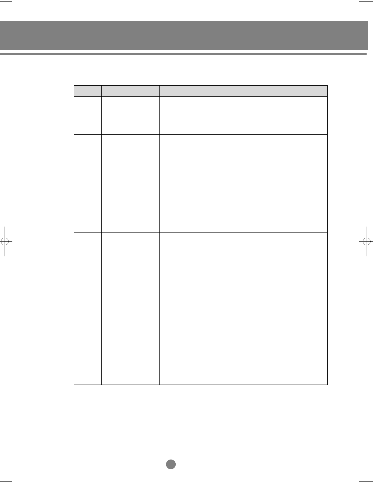
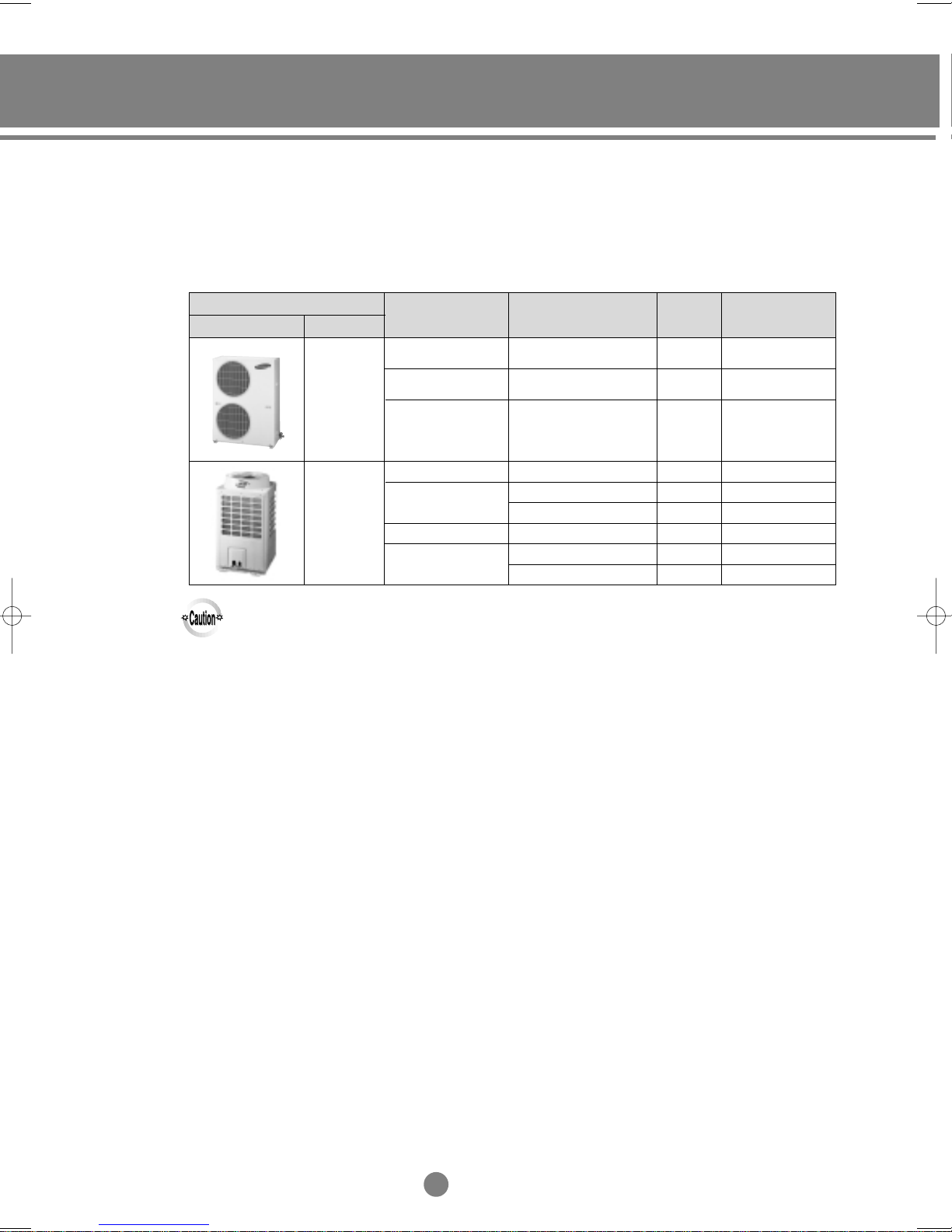
(1) Outdoor unit
1) Cooling only
Design
Main
◆ The system enables the connection of indoor units with a total capacity of between 50 to 130% of that of
the corresponding outdoor unit but where this capacity ratio exceeds 100% then the actual capacity of
each indoor unit will fall a little short of its individual rated capacity when all the units are operated
simultaneously. (Except for the Middle East models)
◆ The specification of super cooler may differ, depending on the model.
Super cooler
-
-
Power supply Model
50Hz
60Hz
50Hz
60Hz
50Hz
60Hz
380~415V, 3ø
208~230V, 1ø
380~415V, 3ø
380~415V, 3ø
380V, 3ø
208~230V, 3ø
380~415V, 3ø
208~230V, 3ø
RVMC060GDM0
RVMC050CBM0
RVMC060GAM0
RVMC060GAM1
MUF7201F1
RVMC070FAM0
RVMC100GAM0
RVMC100FAM0
Capacity(HP)
6
5
6
6
7.5
7.0
10
10
Refrigerant
R407C
R22
R22
R22
R22
R22
R22
R22
18
I
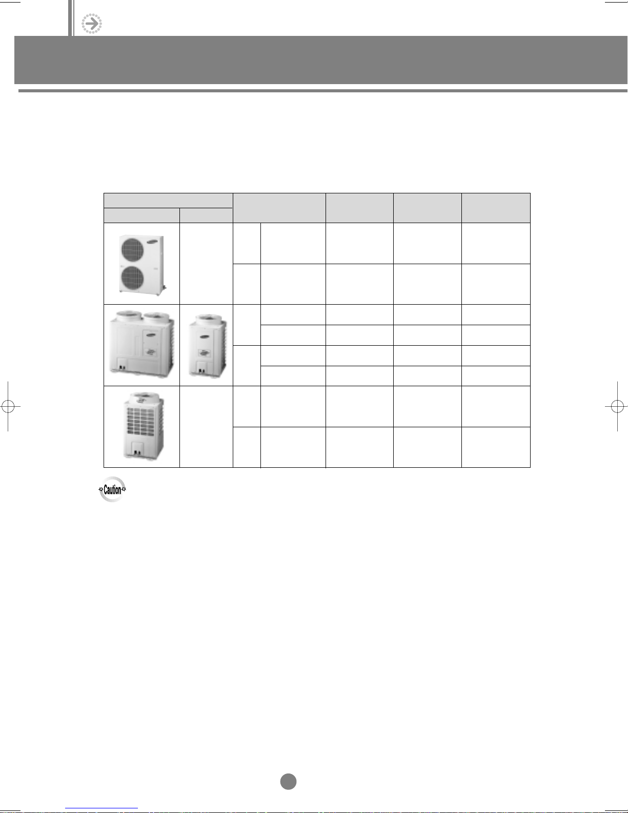
Main
Design
Super cooler
Max. connectible
indoor units
Total capacity of indoor
units (kW, ISO standard)
Super
cooler
Remark
8
7
8
8
10
14
-
14
◆ The system enables the connection of indoor units with a total capacity of between 50 to 130% of that of
the corresponding outdoor unit but where this capacity ratio exceeds 100% then the actual capacity of
each indoor unit will fall a little short of its individual rated capacity when all the units are operated
simultaneously. (Except for the Middle East models)
◆ The specification of super cooler may differ, depending on the model.
8.0~20.8
7.2~18.8
8.0~20.8
8.0~16.0
10.5~21.0
10.5~27.3
10.5~21.0
14.0~36.4
14.0~28.0
14.0~36.4
14.0~28.0
-
-
-
-
For the Middle East
O
For the Middle East
-
-
For the Middle East
-
-
For the Middle East
-
-
For the Middle East
19
I
Ι
. Overview
2. DVM line-up
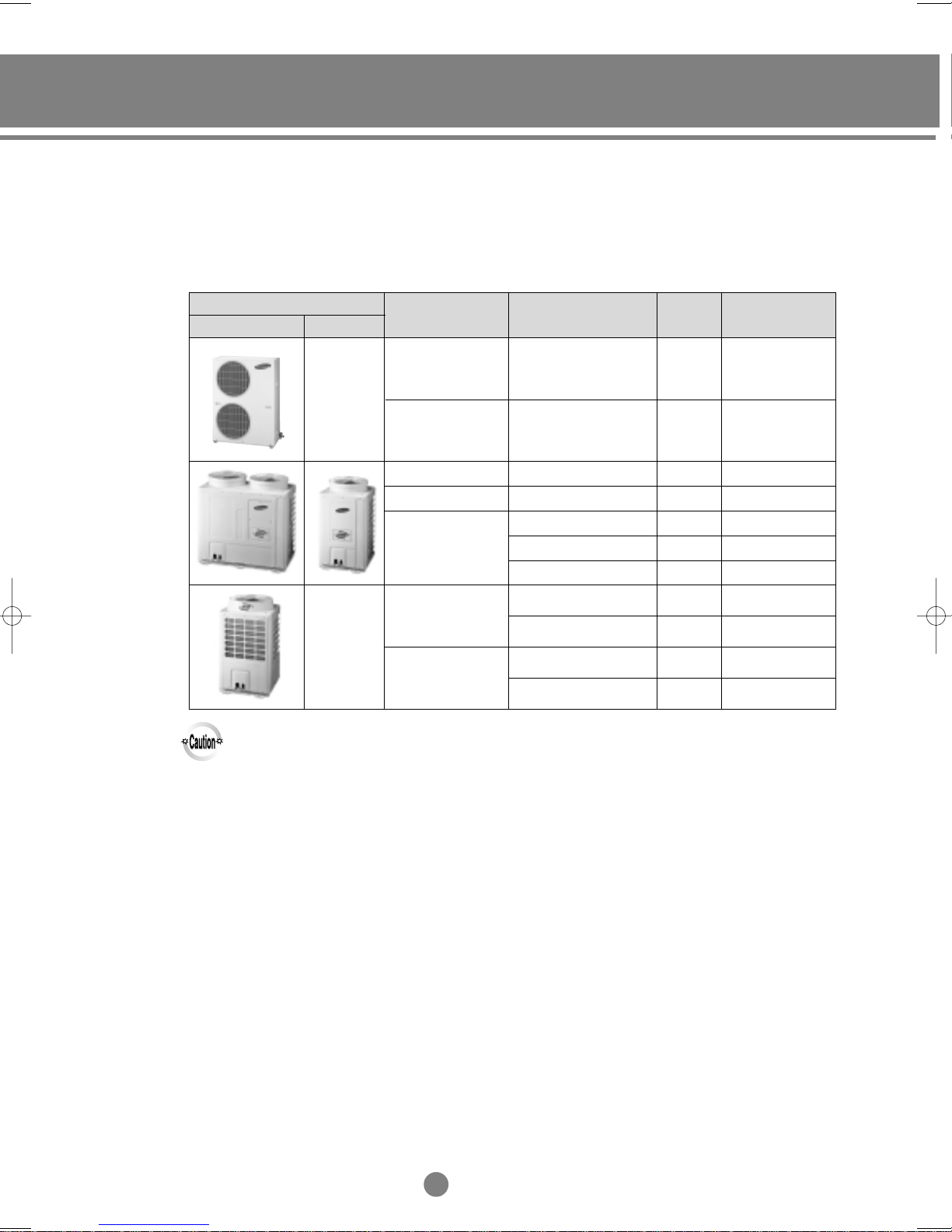
2) Heat pump
Design
Main
◆ The system enables the connection of indoor units with a total capacity of between 50 to 130% of that of
the corresponding outdoor unit but where this capacity ratio exceeds 100% then the actual capacity of
each indoor unit will fall a little short of its individual rated capacity when all the units are operated
simultaneously. (Except for the Middle East models)
◆ The specification of super cooler may differ, depending on the model.
Super cooler
-
-
Power supply Model
50Hz
60Hz
50Hz
60Hz
380~415V, 3ø
380~415V, 3ø
208~230V, 1ø
380~415V, 3ø
380~415V, 3ø
380~415V, 3ø
208~230V, 3ø
RVMH060GBM0
RVMH060GDM0
RVMH050CBM0
RVMH080GAM0
RVMH100GAM0
RVMH100GCM0
RVMH100FAM0
Capacity(HP)
6
6
5
8
10
10
10
Refrigerant
R22
R407C
R22
R22
R22
R22
R22
20
I
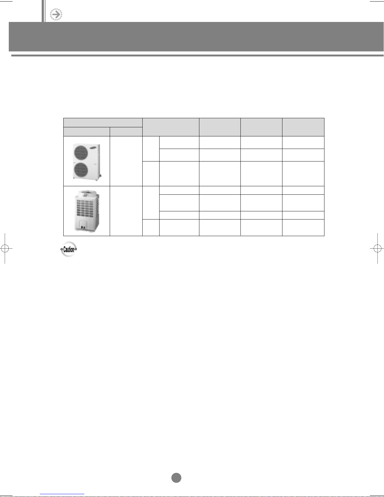
Main
Design
Super cooler
Max. connectible
indoor units
8
Total capacity of indoor
units (kW, ISO standard)
8.0~20.8
Super
cooler
-
Remark
8
7
11
14
-
◆ The system enables the connection of indoor units with a total capacity of between 50 to 130% of that of
the corresponding outdoor unit but where this capacity ratio exceeds 100% then the actual capacity of
each indoor unit will fall a little short of its individual rated capacity when all the units are operated
simultaneously. (Except for the Middle East models)
◆ The specification of super cooler may differ, depending on the model.
14
14
8.0~20.8
7.2~18.8
11.0~29.0
14.0~36.4
14.0~28.0
14.0~36.4
14.0~36.4
14.0~28.0
-
-
-
-
-
-
-
-
For Middle East
For Middle East
21
I
Ι
. Overview
2. DVM line-up
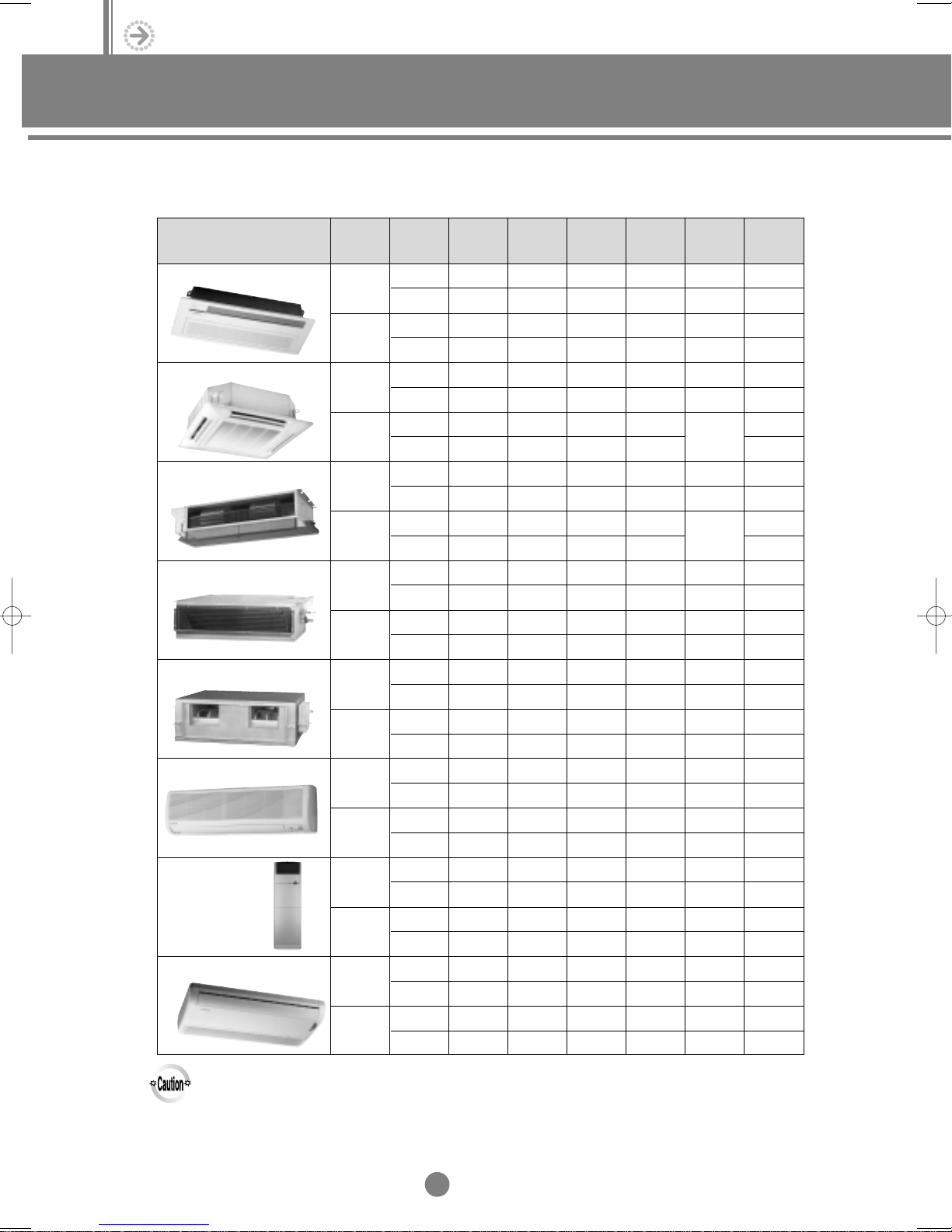
(2) Indoor unit
Design
1-way cassette type
4-way cassette type
Duct type(Low silhouette)
Duct type (Built-in)
Duct type(High pressure)
Wall-mounted type
Floor standing type
Ceiling type
Power
supply
50Hz
60Hz
50Hz
60Hz
50Hz
60Hz
50Hz
60Hz
50Hz
60Hz
50Hz
60Hz
50Hz
60Hz
50Hz
60Hz
2.0kW
(7000Btu/h)
AVMKC020EA0
AVMKH020EA0
AVMKC020CA0
AVMKH020CA0
AVMBC020EA0
AVMBH020EA0
AVMBC020CA0
AVMBH020CA0
AVMWC020EA0
AVMWH020EA0
AVMWC020CA0
AVMWH020CA0
2.6kW
(9000Btu/h)
AVMKC026EA0
AVMKH026EA0
-
-
-
-
-
-
-
AVMBC026EA0
AVMBH026EA0
-
-
-
-
AVMWC026EA0
AVMWH026EA0
-
-
-
-
-
-
-
-
(11000Btu/h)
-
AVMKC032CA0
-
AVMKH032CA0
-
-
-
-
-
-
-
-
-
AVMBC032CA0
-
AVMBH032CA0
-
-
-
-
-
AVMWC032CA0
-
AVMWH032CA0
-
-
-
-
-
-
-
-
3.2kW
-
-
-
-
-
-
-
-
-
-
-
-
-
-
-
-
-
-
-
-
-
-
-
-
-
-
3.5kW
(12000Btu/h)
AVMKC035EA0
AVMKH035EA0
-
-
-
-
-
-
-
-
-
AVMBC035EA0
AVMBH035EA0
-
-
-
-
-
AVMWC035EA0
AVMWH035EA0
-
-
-
-
-
-
-
-
-
-
4.0kW
(13500Btu/h)
AVMKC040CA0
AVMKH040CA0
AVMBC040CA0
AVMBH040CA0
AVMWC040CA0
AVMWH040CA0
(18000Btu/h)
-
-
-
AVMCC052EA0
-
AVMCH052EA0
AVMCC052CA0
ABM1800B1
-
AVMCH052CA0
-
AVMDC052EA0
-
AVMDH052EA0
AVMDC052CA0
ADM1800B1
-
AVMDH052CA0
-
AVMBC052EA0
-
AVMBH052EA0
AVMBC052CA0
AVMBH052CA0
-
-
-
-
-
AVMWC052EA0
-
AVMWH052EA0
AVMWC052CA0
AVMWH052CA0
-
-
-
-
-
AVMFC052EA0
-
AVMFH052EA0
-
AVMFC052CA0
-
AVMFH052CA0
5.2kW
-
-
-
-
-
-
-
-
-
-
-
-
6.0kW
(20000Btu/h)
-
-
-
-
-
-
-
-
-
-
-
-
-
-
-
-
-
-
-
-
-
-
-
AVMPC060EA0
AVMPH060EA0
AVMPC060CA0
AVMPH060CA0
-
-
-
-
◆ The design and capacity of indoor unit are subject to change without notice.
22
I
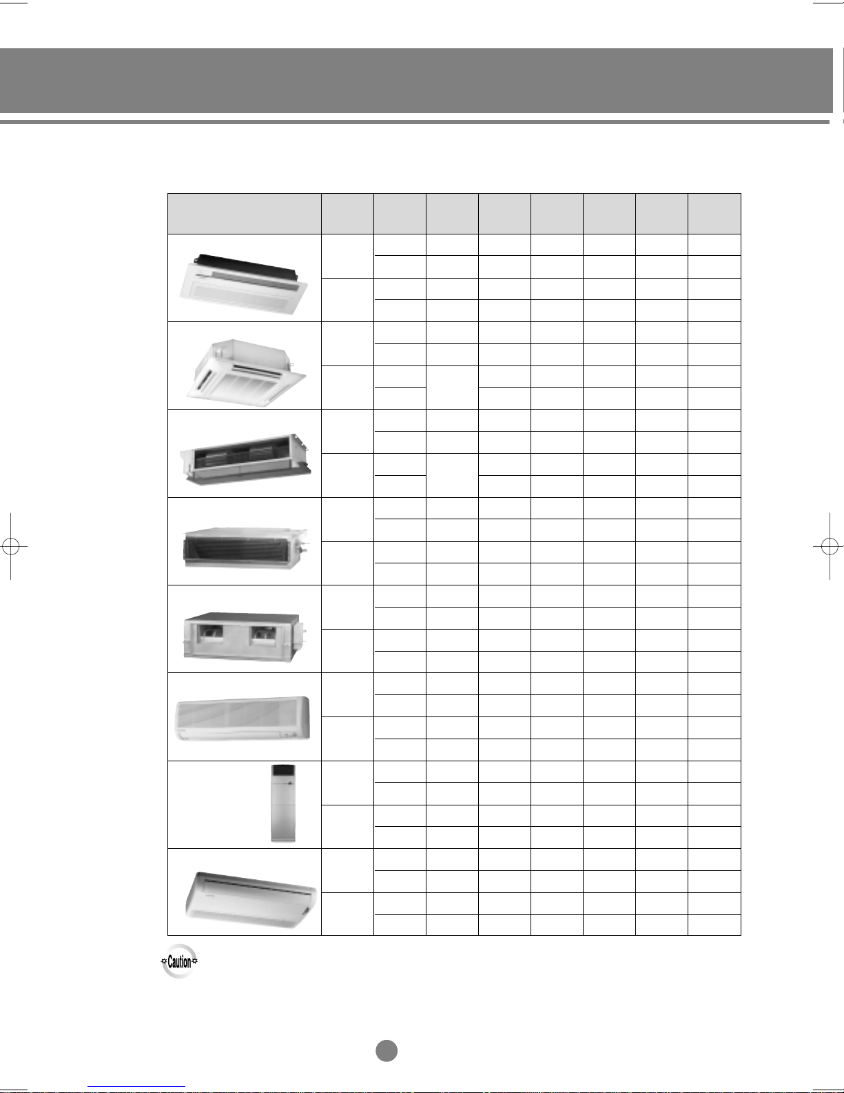
Design
1-way cassette type
4-way cassette type
Duct type(Low silhouette)
Duct type (Built-in)
Duct type(High pressure)
Wall-mounted type
Floor standing type
Ceiling type
Power
supply
50Hz
60Hz
50Hz
60Hz
50Hz
60Hz
50Hz
60Hz
50Hz
60Hz
50Hz
60Hz
50Hz
60Hz
50Hz
60Hz
7.0kW
(24000Btu/h)
-
-
-
AVMCC070EA0
AVMCH070EA0
-
AVMDC070EA0
AVMDH070EA0
-
-
AVMBC070EA0
AVMBH070EA0
-
-
-
-
-
-
AVMWC070EA0
AVMWH070EA0
-
-
AVMPC070EA0
AVMPH070EA0
-
-
AVMFC070EA0
AVMFH070EA0
-
-
7.2kW
(24000Btu/h)
AVMCC072CA0
ABM2400B1
AVMCH072CA0
AVMDC072CA0
ADM2400B1
AVMDH072CA0
AVMBC072CA0
AVMBH072CA0
AVMWC072CA0
AVMWH072CA0
AVMPC072CA0
AVMPH072CA0
AVMFC072CA0
AVMFH072CA0
(28000Btu/h)
-
-
-
-
-
-
-
-
-
-
-
-
-
-
-
-
-
AVMPC082EA0
-
AVMPH082EA0
-
-
8.2kW
-
-
-
-
-
-
-
-
-
-
-
-
-
-
-
-
-
-
-
-
-
-
-
-
-
-
-
-
-
-
8.3kW
(28000Btu/h)
AVMPC083CA0
AVMPH083CA0
(36000Btu/h)
-
-
-
-
-
AVMCC105EA0
-
AVMCH105EA0
-
AVMCC105CA0
-
AVMCH105CA0
-
-
-
-
-
-
-
-
-
AVMHC105EA0
-
AVMHH105EA0
-
AVMHC105CA0
-
AVMHH105CA0
-
-
-
-
-
-
-
-
-
-
10.5kW
(44000Btu/h)
-
-
-
-
-
-
-
-
-
-
-
AVMHC128EA0
AVMHH128EA0
AVMHC128CA0
AVMHH128CA0
-
-
-
-
-
-
-
-
-
-
-
-
12.8kW
-
-
-
-
-
-
-
-
-
-
-
-
-
-
-
-
-
-
-
-
-
-
-
-
-
-
-
-
Remark
◆ The design and capacity of indoor unit are subject to change without notice.
23
I
ΙΙ
Control system
1.
Remote controller
1-1. Wireless remote controller
1-2. Wired remote controller
1-3. Centralized controller
1-4. Function controller
2.
Receiver & display unit (Duct type)
2-1. Concealed type
2-2. Standard type
3.
Interface module
4.
Installation
4-1. Wireless remote controller
4-2. Wired remote controller
4-3. Centralized controller
4-4. Function controller
4-5. Receiver & display unit - concealed type
4-6. Receiver & display unit - standard type
4-7. Interface module
2
3
4
4
5
6
8
9
12
17
19
20
21
5.
Assigning address
5-1. Indoor unit
5-2. Outdoor unit
6.
Indoor unit PCB option code
6-1. PCB option code input method
6-2. Option code
7.
S-Net
Integrating power distribution system
8.
9.
Building management system
23
24
25
30
ΙΙ
. Control System
1. Remote controller
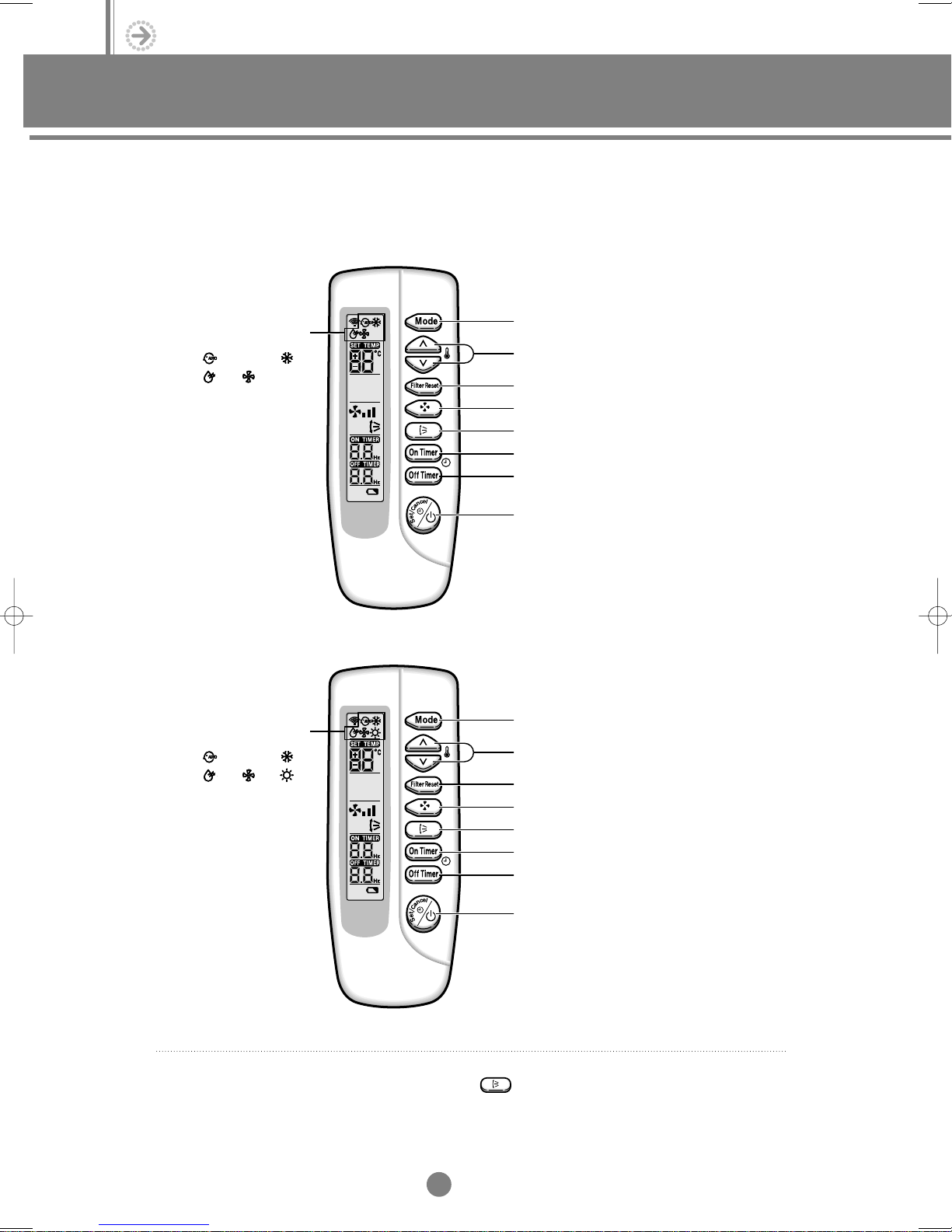
1-1. Wireless remote controller
(1) Cooling only
Operating mode
Automatic
Dry Fan
(2) Heat pump
Operating mode
Automatic
Dry HeatFan
Cool
Cool
Operating mode selection button
2)
Temperature adjustment buttons
✻
Filter Reset button
Fan speed adjustment button
Air flow direction adjustment button
On timer button
Off timer button
On/Off & Timer set/cancel button
Operating mode selection button
2)
Temperature adjustment buttons
✻
Filter Reset button
Fan speed adjustment button
Air flow direction adjustment button
On timer button
Off timer button
1)
✻
1)
✻
✻ 1) Duct type air conditioner does not have function of adjusting air flow direction.
Therefore, the function is not operated even if you press .
✻ 2) Temperature display is
O
C or OF.
On/Off & Timer set/cancel button
2
ΙΙ
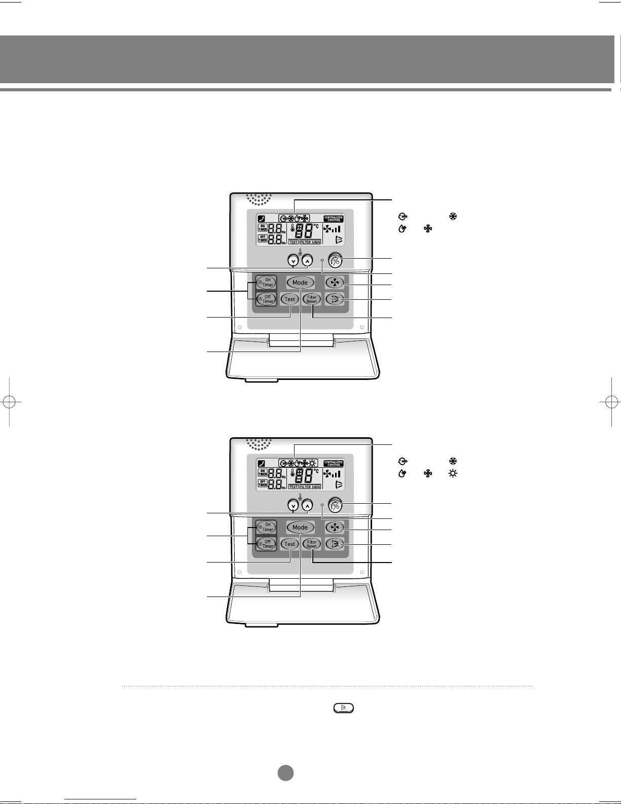
1-2. Wired remote controller
(1) Cooling only
3)
✻
Operating mode
Automatic Cool
Dry Fan
Temperature
adjustment buttons
✻
On/Off timer button
Test operation button
Operating mode
selection button
(2) Heat pump
Temperature
adjustment buttons
On/Off timer button
✻
2)
On/Off & Timer set/cancel button
Operating indicator
Fan speed adjustment button
1)
Air flow direction adjustment button
✻
Filter Reset button
Operating mode
Automatic Cool
Dry HeatFan
2)
On/Off & Timer set/cancel button
Operating indicator
Fan speed adjustment button
1)
Air flow direction adjustment button
✻
Test operation button
Operating mode
selection button
✻ 1) Duct type air conditioner does not have function of adjusting air flow direction.
Therefore, the function is not operated even if you press .
✻ 2) Temperature display is
✻ 3) You must select either cooling only or heat pump depending on the type
of air conditioner when installing the remote controller.
O
C or OF.
Filter Reset button
3
ΙΙ
ΙΙ
. Control System
1. Remote controller
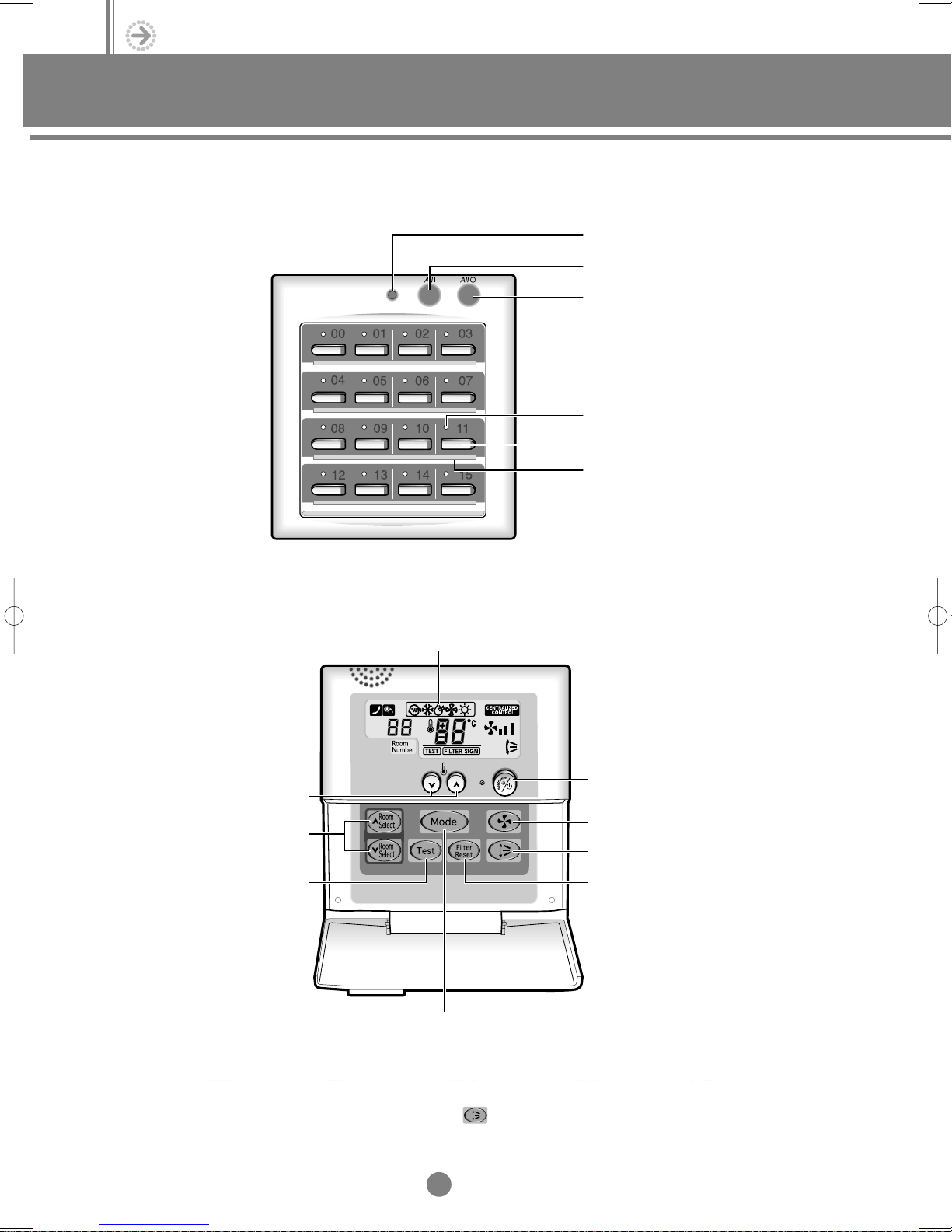
1-3. Centralized controller
Operating lamp
All On button
All Off button
On/off indicators
Individual On/Off button
Index
1-4. Function controller
Temperature adjustment
buttons
Indoor unit selection buttons
Test button
2)
✻
Operating mode
Mode selection button
On/Off button
Fan speed adjustment button
Air flow direction adjustment button
Filter reset button
1)
✻
✻ 1) Duct type air conditioner does not have function of adjusting air flow direction.
Therefore, the function is not operated even if you press .
✻ 2) Temperature display is
O
C or OF.
4
ΙΙ
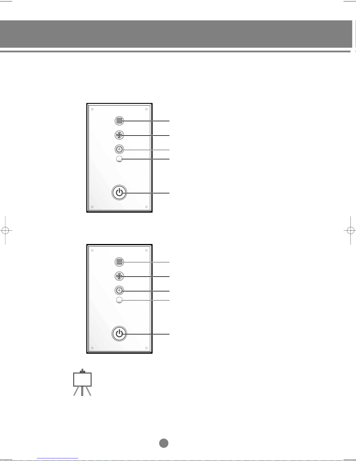
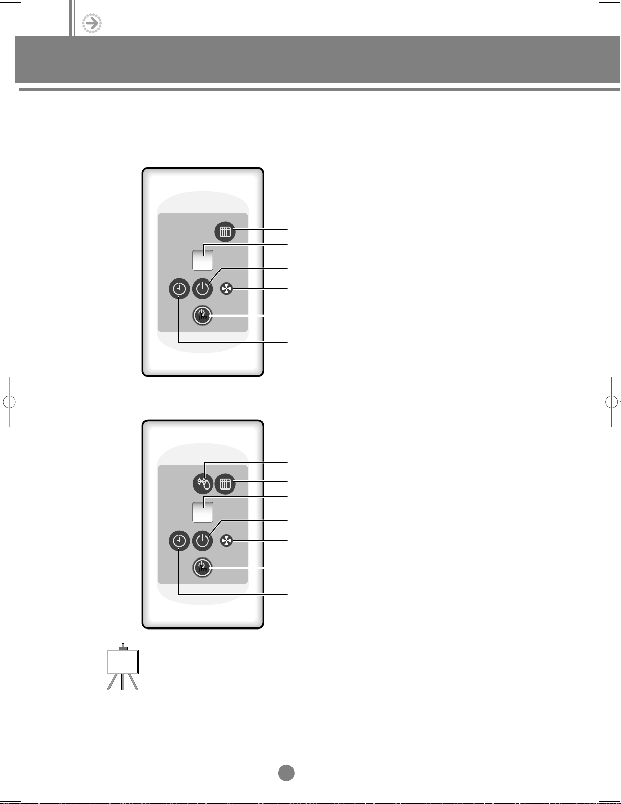
2. Receiver & display unit (For Duct)
2-1. Concealed type
(1) Cooling only
Filter sign indicator
Fan indicator
Timer indicator
Remote control sensor
On/Off button
(2) Heat pump
Note
◆ The shape of receiver & display unit for cooling model is same with heat pump’s. But their function
and color of indicators are different each other.
◆ This receiver & display unit should be applied to duct type air conditioners when using the wireless
remote controller, and the receiver & display unit wire kit must be purchased together.
Filter sign indicator
Fan indicator
Timer indicator
Remote control sensor
On/Off button(Blue) & Removing frost
indicator(Red)
5
ΙΙ
ΙΙ
. Control System
2. Receiver & display unit (For Duct)
2-2. Standard type
(1) Cooling only
Filter sign indicator
Remote control sensor
On/Off indicator
Fan indicator
On/Off button
(2) Heat pump
Timer indicator
Removing frost indicator
Filter sign indicator
Remote control sensor
On/Off indicator
Fan indicator
On/Off button
Timer indicator
Note
◆ This receiver & display unit should be applied to duct type air conditioners when using the wireless
remote controller, and the receiver & display unit wire kit must be purchased together.
6
ΙΙ
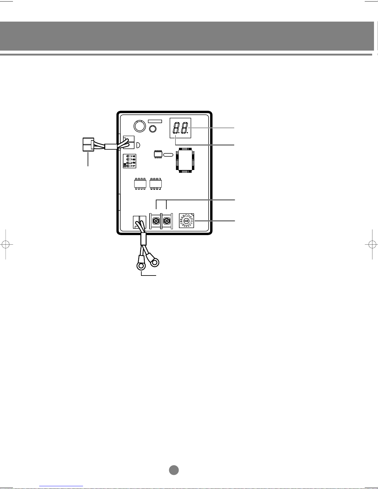
3. Interface module
CN01
F1 F2
R2 R1
To outdoor unit PCB
(DC 12V)
Group address display
Indoor unit address display
To centralized controller /
S-Net converter
Interface module address setting
(Each Interface module has its
own address)
From F1, F2 terminal
in the outdoor unit
7
ΙΙ
ΙΙ
. Control System
4. Installation
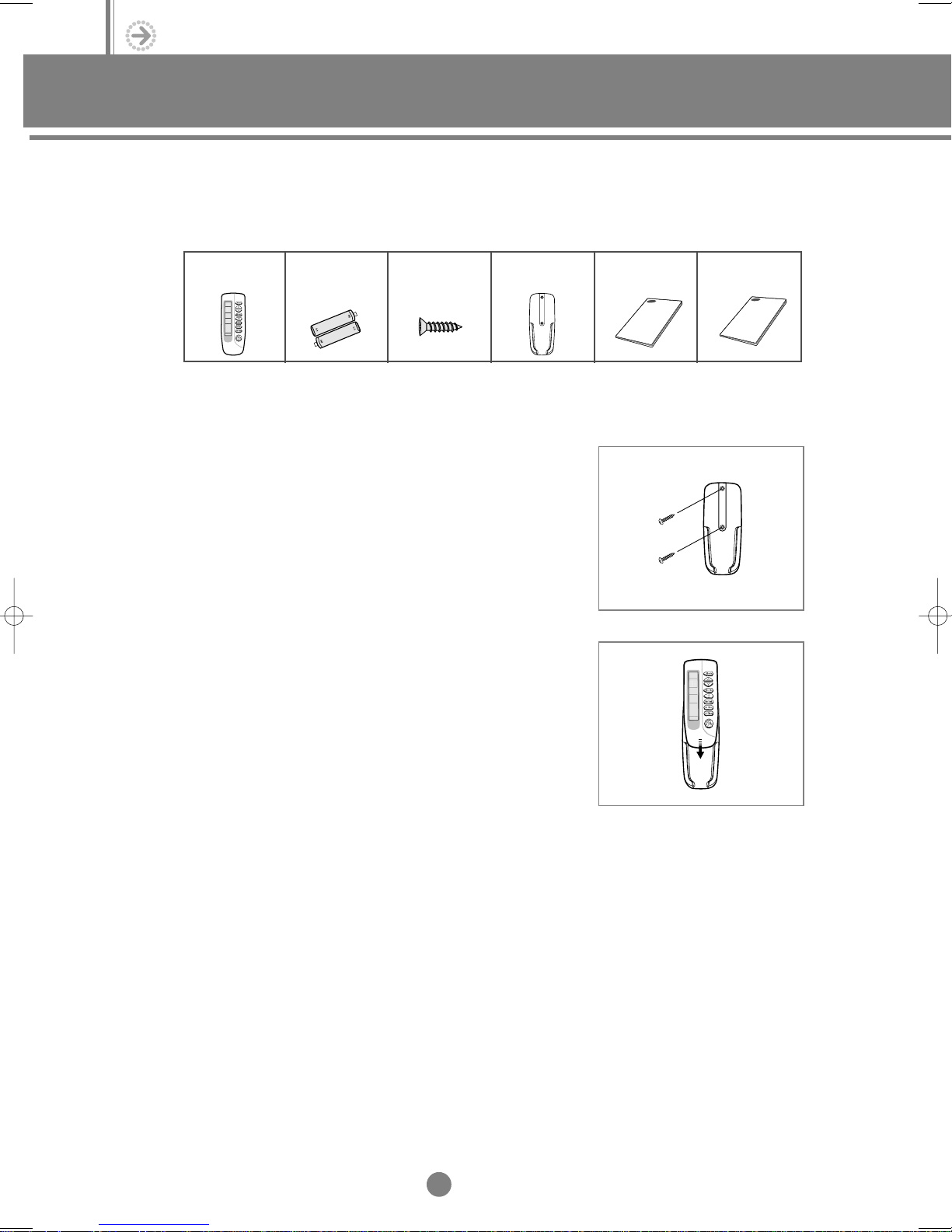
4-1. Wireless remote controller
(1) Accessories
Wireless remote
controller(1)
Battery for
wireless remote
controller(2)
M4x12 tapped
screw(2)
Remote control
holder(1)
(2) Installation
Choose a position where:
◆
The signal from the remote controller will not be blocked
(by a curtain for example)
◆
The remote controller is not exposed to direct sunlight or heat
◆
The wireless remote controller is at least one meter away from
a television or stereo system to avoid generating any parasites
To attach the holder to the wall, proceed as follows.
1) With a pencil, mark the positions of the two holes on the
wall where the holder is to be installed.
2) Drill the two holes and insert plugs as required for the type
of wall on which the holder is being installed.
3) Screw the holder into position.
Owner’s
instructions(1)
Installation
manual(1)
8
ΙΙ
 Loading...