


SAMSUNG RT44MBSW Service Manual
Model :RT40MA / MB
RT44MA / MB
REFRIGERATOR CONTENTS
1. Product Specifications
2. Safety Warnings
3. Specifications of Electric Components
4. Electric Circuit Diagram
5. External Size and Designations
6. Refrigeration Cycle and Cool Air Circulation
7. Circuit Operation Theory
8. Troubleshooting
9. Exploded View and Part List
10. Disassembly of Freezing Compartment
11. Disassembly of Refrigerating Compartment

1
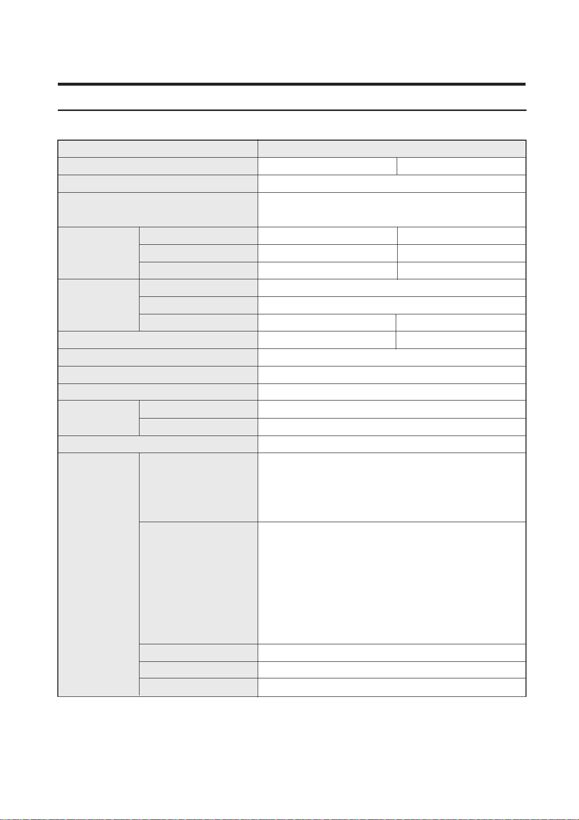
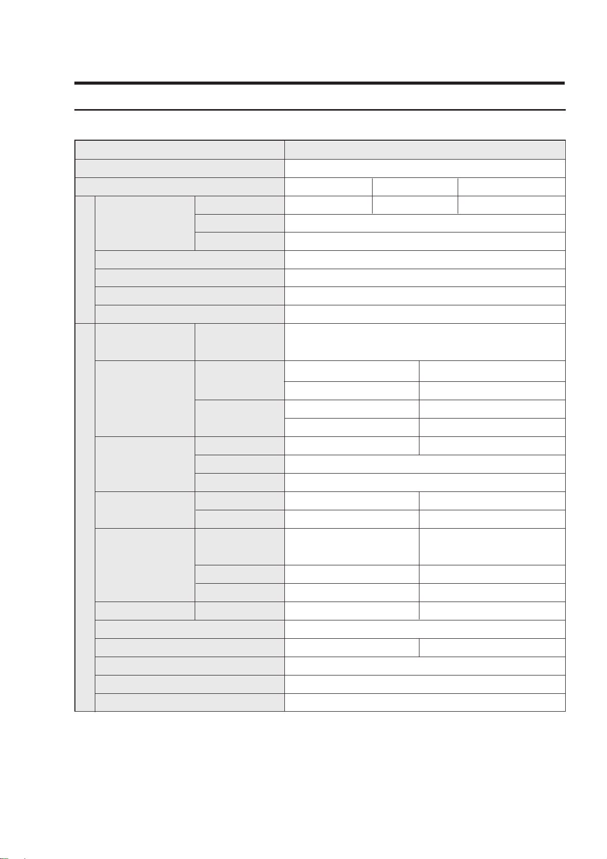
1. Product Specifications
ITEM
Model name
SPECIFICATION
Freezer
Refrigerator
Total
RT40MA/MB
RT44MA/MB
87(3.1) 87(3.1)
260(9.2) 282(10.0)
347(12.3)
110~115V/60Hz, 127V/60Hz, 220V/5~60Hz, 230~240V/50
290W/310W
forced convection
HFC-134a
150g
4 STAR
369(13.1)
670x640x1660
(670)
670x640x1730
(670)
59/69(kg) 63/73(kg)
Vailable
Capacity(cu.ft)
Net Dimension
(WidthxDepthxHeight)
Rated Voltage & frequency
Rated Power Defrost, Heater
Type of Refrigerator
Refrigerant
Refrigerant Mass
Freezing Capicity
Weight (Net/Gross)
[CFC-FREE]
2
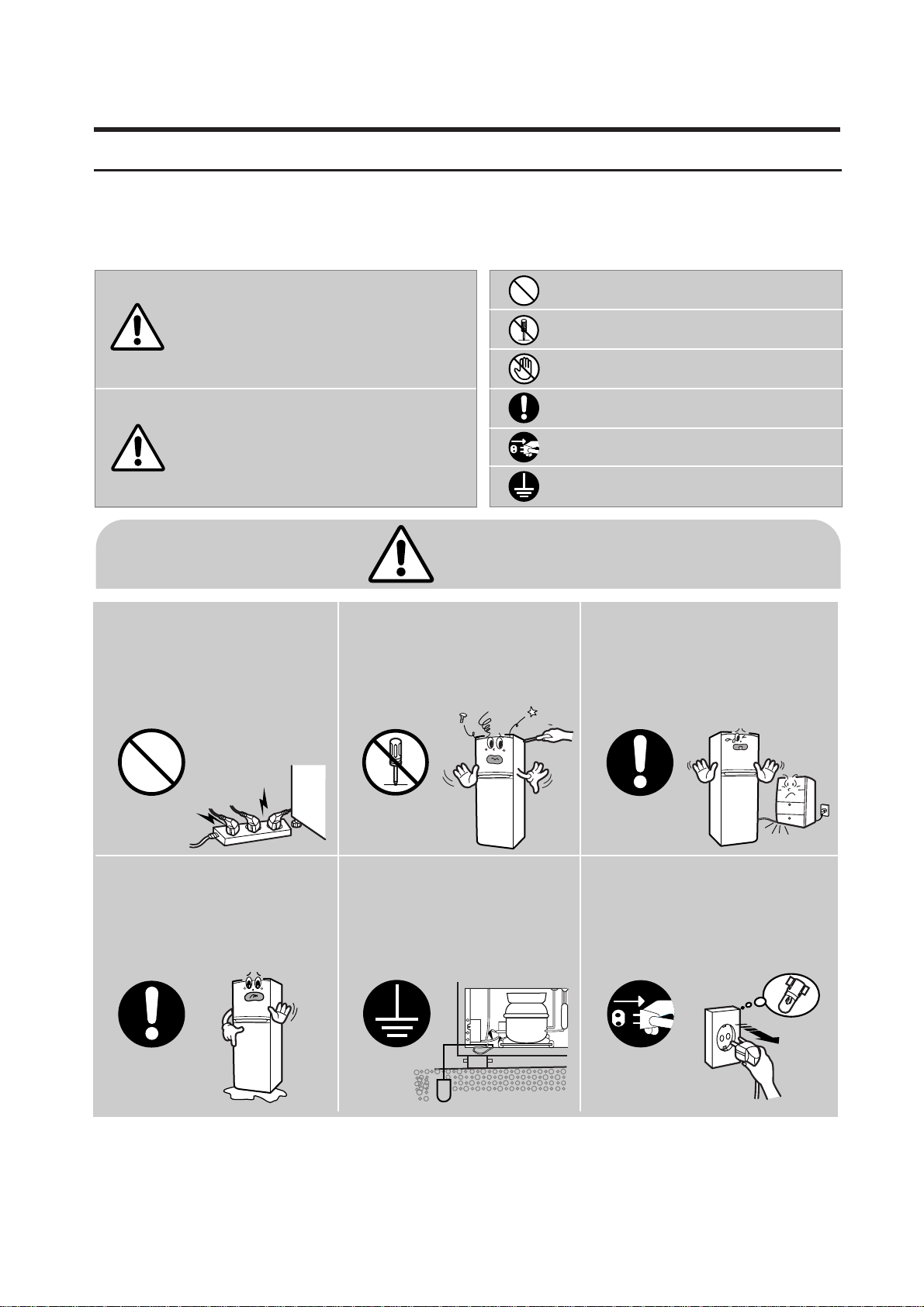
2. Safety warnings
Read all instructions before using this appliance in order to avoid risk of accident or possible damage.
W arning/Caution
Description of symbols
Indicates prohibition
Do not disassemble
Do not contact
Follow Adhere the instruction strictly
Unplug from the electrical outlet
Earth the appliance to avoid the
risk of an electric shock
Do not plug multiple electrical
appliances into the same outlet.
• This may cause abnormal
heating or a fire hazard.
Do not attempt to make repairs
yourself.
• This could lead to fire hazard or
abnormal operation causing
severe personal injury .
Make sure the power cord is not
crushed or damaged.
• Repair immediately all power cords
or outlets that have become frayed
or otherwise damaged.
Check the operating environment.
• Do not install the refrigerator in a
humid (with condensation) location
or on an unstable surface.
Be sure the earth.
• If earthing is not done, it will
cause breakdown & electric
shock.
Pull the power plug out for
exchanging electrical equipment.
• It may cause electric shock.
Warning
This symbol is intended to
alert the user to the
possible death or injury.
Caution
This symbol is intended to
alert the user to the
possible injury or damage.
Warning
Prohibition Do not disassemble
Earth Unplug
3
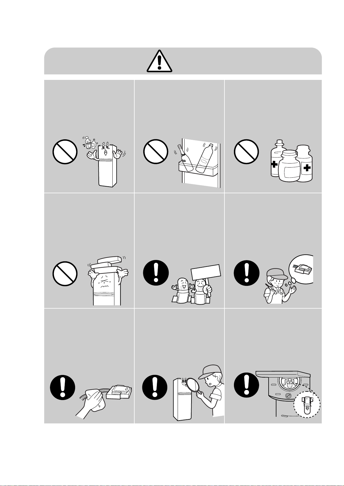
Caution
Do not put bottles or kinds of
glass in the freezer.
• Freezing of the contents
may inflict a wound.
Do not store narrow and
lengthy bottles or foods in a
small multi-purpose room.
• It may hurt you when refrigerator
door is opened and closed
resulting in falling stuff down.
Do not store pharmaceutical
products, scientific materials,
etc, in the refrigerator.
• The products which cotrolled by
temperature shall not be stored
in the refrigerator.
Do not store articles on the
product.
• Opening or closing the door
may throw down which may
inflict a wound.
Use the rated components on
the replacement.
• Check the correct model, rated
voltage, rated correct, operating
temperature and so on.
On repair, make sure that the wires
such as harness should be bundled
tightly .
• Bundle tightly wires in order not to
be detached by the external force
and then not to be wet.
On repair, remove completely
dust or other things of housing
parts, harness parts, and check
parts.
• Cleaning may prevent the possible
fire by tracking or short
After repair, check the assembled
state of components.
• It must be in the same assembled
state when compared with the
state before disassembly .
Check if there is any trace indicating
the permeation of water.
• If there is that kind of trace, change
related components or do the
necessary treatment such as taping
using the insulating tape.
Prohibition
Prohibition
Prohibition Prohibition
Rated
components
4
1 Base Tray Ice
1 Case Tray Ice
1 Shelf Freezer
1 Vegetable Partition
1 Case Chilled Room
2 Shelf Refrigerator
1 Cover Vegetable
1 Case Vegetable
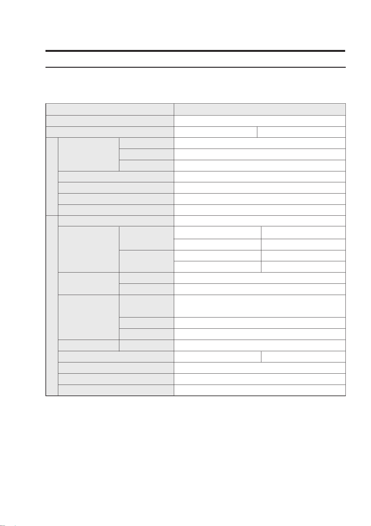
ITEM
Model name
Type
Power Source
SPECIFICATION
Freezer
Refrigerator
Total
Width
Depth(MA)
Height
Net weight (Kg)
Refrigerant
Temperature Control
Defrosting
Cabinet
Door
Door
Storage
Accessory
Parts
Inside
Storage
Angle Adjustment
Movable Caster
Interior Lamp
Liner/Door Panel
RT40MA/MB
RT44MA/MB
87 87
260 282
347/12.3 369/13.1
670
640(670)
17301660
59 63
R134a (150g)
Dial (Resistance)
Automatic (Start-Finish by PCB)
Cyclo-Pentane
Cyclo-Pentane
ABS (SD-0150)
2 Guard-Freezer
1 Guard-Egg,1 Guard-Bottle
2 Guard-Variety
1 Guard-Jumbo
Refrigerator (Freezer)
2 (Rear)
2 Legs (front)
2-Door Freezer/Refrigerator
AC110~115V/60Hz, 127V/60Hz
220V/50~60Hz, 230~240V/50Hz
3. Specifications of Electric Components
Net Capacity
(
ℓℓ
/cu.ft)
Net Dimension
(mm)
Foam
insulation
[CFC-FREE]
5
[CFC-FREE]
ITEM
Model
Power source
STANDARD(MECHANICAL TYPE)
Evaporator
Condenser
Dryer
Capillary tube
Resistor Heater
Heater-defrost
Lamp
Door-Switch
Earth screw
Model
Starting type
Oil charge
Compressor
Refrigerator
Thermal fuse
Model
Thermostat
Bimetal
(OFF/ON)
Defrost-thermo
PTC-relay
Capacitor
Overload
protector
Type
Defrosting
Interval
Model
Resistance
Close temp.
Open temp.
Running
Defrost-timer
Refrigeration Cycle
Electrical
R.S.C.R
110~115V/60Hz
UK162C-L1U/T3
127V/60Hz
UK162P-L1U/T3
220V/50~60Hz
SK182H-L2U/E02
FREOL α–15c / 200cc
Fin type
Natural convection type
Molecular sieve (XH-9, 13g)
ID 0.75 x L3400 (mm)
PFN-174S-05F (ON:5.5
˚C±
1.5˚COFF:+3.0
˚C±
1.5˚C)
250V/0.5A, 125V/1.5A
BSBN(Brass screw)
Rating Voltage/Ampere
Open temperature
Rating Voltage/Ampere
Open temperature
TMDE714F1
AC 250V / 5A
ON:-5±3˚C/OFF:12±3˚C
AC 250V / 10A
77±10˚C
TD-20CSA
69±9˚C
120±5˚C
250VAC/12
µF
69±9˚C
125±5˚C
350VAC/5.0
µF
J531Q33E100M 200-2
10Ω-2PIN
6hr 40min(60Hz)/8hr(50Hz)
12Min
J531Q34E220M350-2
22Ω-2PIN
4TM419
NHBYY-53
4TM308
PHBYY-53
MORS 1.2W
290W/45Ω 290W/167Ω
220V~240V/15W
RT40/44MA/MB
6
[CFC-FREE]
ITEM
Model
Power source
STANDARD(SEMI ELECTRIC TYPE)
Evaporator
Condenser
Dryer
Capillary tube
Heater-defrost
Lamp
Door-Switch
Earth screw
Model
Starting type
Oil charge
Compressor
Sensor
Thermal fuse
Model
Sensor
Defrost-sensor
PTC-relay
Capacitor
Overload
protector
Model
Resistance
Close temp.
Open temp.
Running
Refrigeration Cycle
Electrical
R.S.C.R
220V/50Hz
230~240V/50Hz
MK172QL1U/E01
FREOL α–15c / 200cc
Fin type
Natural convection type
Molecular sieve (XH-9, 13g)
ID 0.75 x L3400 (mm)
502AT
Rating Voltage/Ampere
Open temperature
Rating Voltage/Ampere
Open temperature
DC 5V
ON:-5˚C±3˚C/OFF:+15˚C
AC 250V / 10A
77˚C±10˚C
J531Q35E330M385-2
33Ω-2PIN
69±9˚C
135±5˚C
350VAC/5.0
µF
4TM232SHBYY-53
290W/167Ω 310W/170Ω
220V~240V/15W
250V/0.5A, 125V/1.5A
BSBN(Brass screw)
RT40/44MA/MB
7
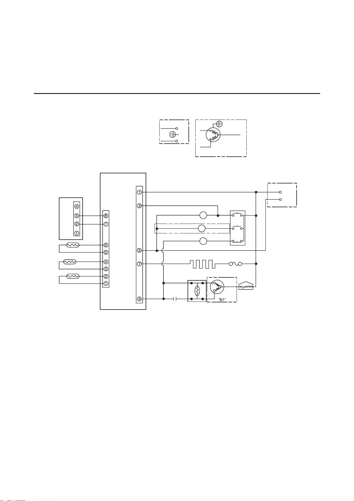
4. Electric Circuit Diagram
●
Semi Electric Control Type
SUB PCB
MAIN PCB
CN01
R ROOM-SENSOR
EXT-SENSOR
EVAP-SENSOR
SK/BLU
RUNNING
CAPACITOR
P.T.C RELAY
PINK
SK/BLU
PINK
25
S
C
COMPRESSOR
RED
WHT
THERMAL FUSE
DEFROST HEATER
FAN MOTOR
PINK
3
12
WHT
R/LAMP
GRY
DOOR SWITCH
RED
RED
N
L
N
E
L
E
M
S
C
COMPRESSOR
"B-2"
“A-2"
“A-1"
GRY
F/LAMP
L
L
WHT/BLK
M
RED
OVERLOAD
PROTECTOR
36
YEL
YEL
WHT
WHT
GRY
GRY
BRN
BRN
RED
WHT
GRY
BRN
CN02
CN01
“A-1" “B-1" : WITHOUT EARTH
“A-2" “B-2" : WITH EARTH
“C" : WITH F/LAMP
GRY-GRAY
RED-RED
BRN-BROWN
YEL-YELLOW
WHT/BLK-WHITE/BLACK
PINK-PINK
WHT-WHITE
SK/BLU-SKY BLUE
E-EARTH
“C"
[220V/50Hz, 230~240V/50Hz]-RT40/44
8
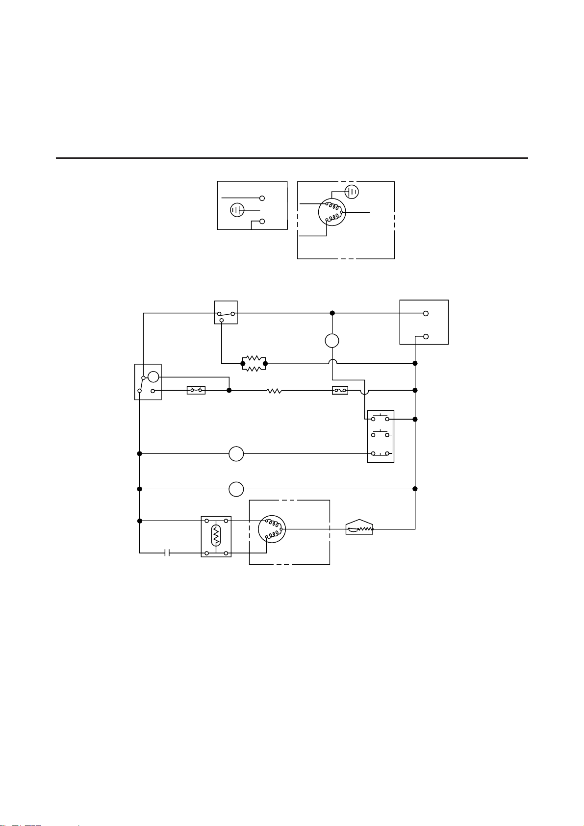
●
Mechanical Type
YEL
WHT
M
BRN
BIMETAL
DEFROST
TIMER
RUNNING
CAPACITOR
P.T.C RELAY
COMPRESSOR
COMPRESSOR
OVERLOAD
PROTECTOR
WHT
BRN R-THERMP
R-HEATER
R/LAMP
GRY
L
N
E
A
N
M
S
C
E
W/BLK RED
RED
RED
RED
PNK
S/BLU
S/BLU
S/BLU
PNK
235
M
S
C
RED
GRY- GRAY
RED- RED
BRN- BROWN
YEL- YELLOW
S/BLU- SKY BLUE
PNK- PINK
BLK- BLACK
WHT- WHITE
W/BLK- WHITE/BLACK
6
FAN MOTOR
COMP. COOLING MOTOR
DOOR-S/W
F.M
S/BLU
C.M
RED
“A-1"
“A-2"
“B-2"
“A-1" “B-1" : WITHOUT EARTH
“A-2" “B-2" : WITH EARTH
“B-1"
L
RED
LC
H
WHT PNK
THERMAL
FUSE
DEFROST
HEATER
1
3
4
2
[110~115V/ 60Hz, 127V/60Hz, 220V/50~60Hz]-RT40/44
9
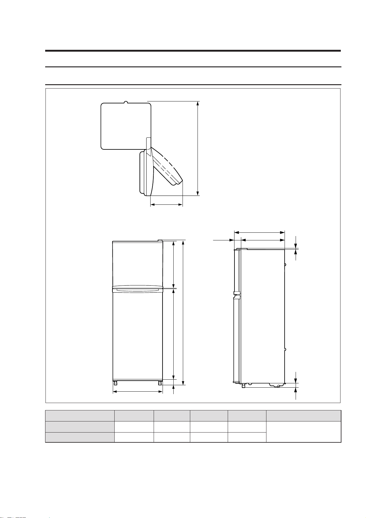
5-1) Product Dimension
670
60
9
B
A
548.5
50
15
C
D
80.5
1250.5
454.1
MODEL
RT40MA/MB
RT44MA/MB
A
1660
1730
B
1103.5
1173.5
C
549.5
549.5
D
640(670)
640(670)
Remark
( )BAR TYPE
5. Extemal size and Designations
10
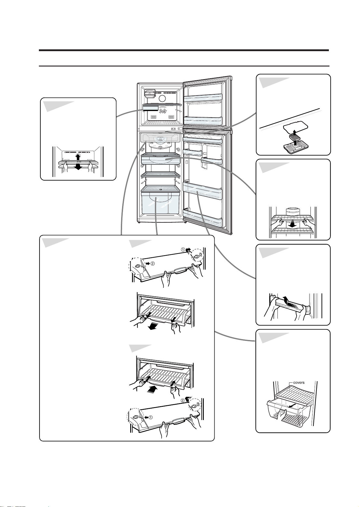
T o remove shelves in the
freezing compartment
• Frist remove the icemaking
molds. Tilt the shell up at
front, then lift it up and pull
it out of the tracks.
To remove bio
deodorizer
• While pushing the front end
knob of the bio deodorizer,
pull it downward to
disengage.
T o remove shelves in the
refrigerating compartment
• Hold the shelf by the front
and pull it forward of the
rack.
To remove shelves in the
chilled compartment
Disassemble
Reassemble
• Lift up the cover, push the
cover to the right (as shown)
until the mounting hook(①)
disengages, then disengage
the other mounting hook (②)
and pull out the cover.
• Pull the shelf forward until it
stops. then lift it up and pull
it out.
• With shelf front raised
slightly, engage, the roller
between the rails and slide it
back.
• To repace the cover, first
engage the mounting hook
(①) as shown, then engage
the other hook (②) and push
in.
To remove door bins
• While pushing the bin
to the left, lift it up to
disengage.
To remove storage
drawers and covers
• Lift up to remove the cover.
Pull the drawer helf way out,
then lifting it up, pull it out
completely.
5-2) Identifying and disassembling the parts
11
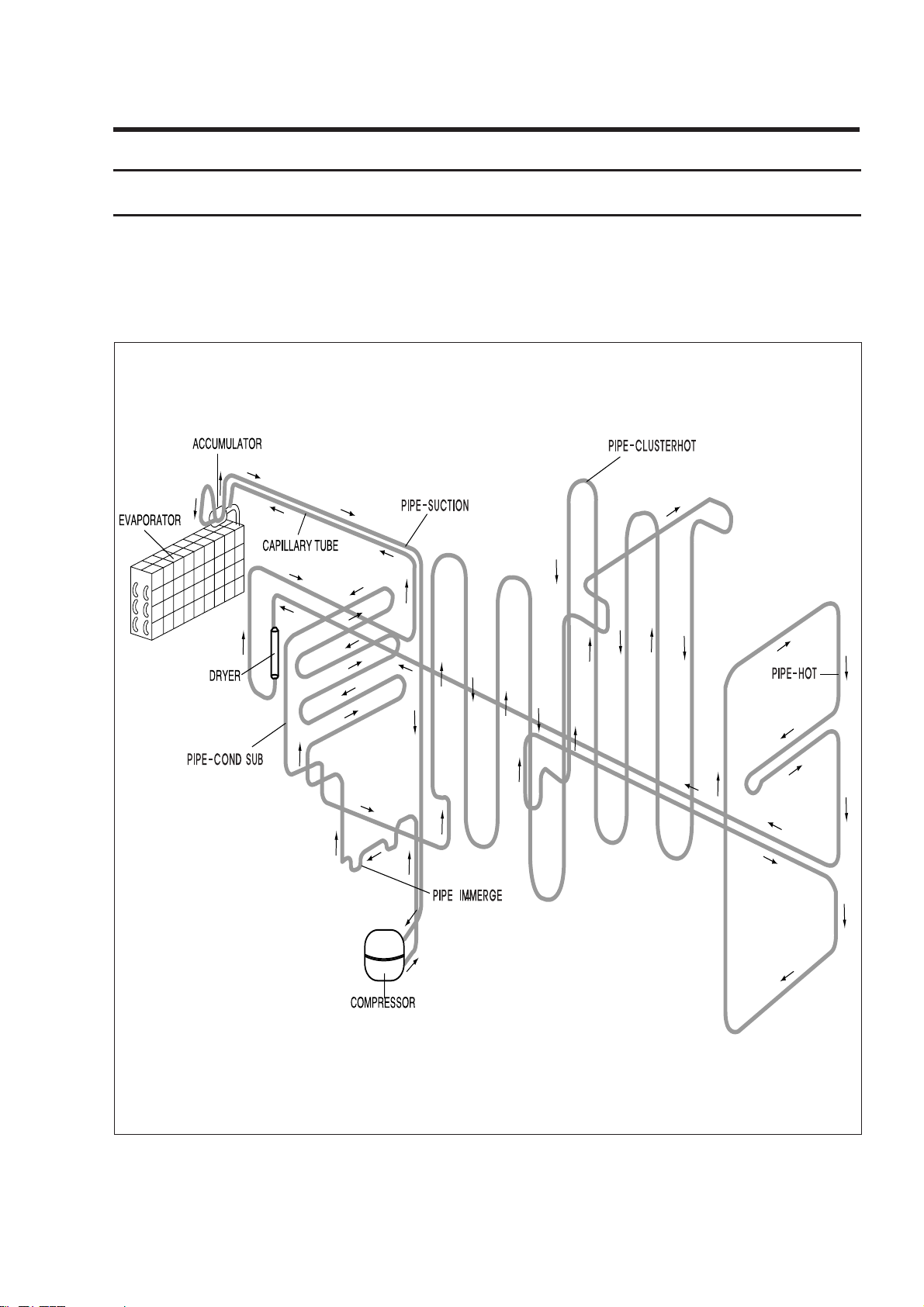
6. Schematic diagram of coolant gas circulation
COMPRESSOR → PIPE IMMERGE → PIPE SUB CONDENSER → PIPE CLUSTER →
PIPE HOT → DRYER→ CAPILLARY TUBE → EVAPORATOR → ACCUMULATOR →
PIPE SUCTION → COMPRESSOR
6-1) Refrigeration Cycle
12
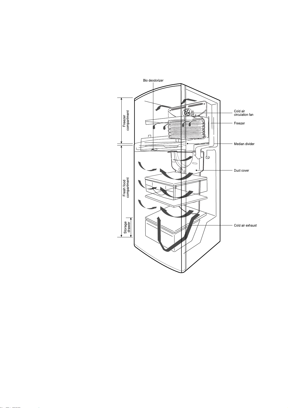
6-2) Cool Air Circulation
• Cold air generated from the
cooling system is distributed to
the freezing compartment and
the refrigerating compartment by
the air circulation fan.
• In the freezing compartment, cold
air is distributed to the
compartment as well as to the
shelves from the cold air exhaust
port, food is frozen in the freezing
compartment by cold air shower.
• Cold air that comes out of the
freezing compartment is
absorbed back to the lower part
of the cooling system through the
suction port on the median
divider.
• In the refrigerating compartment,
cold air is distributed to the duct
cover through the median divider.
Cold air supplied to the duct
cover passes through the
refrigerating compartment.
• After cooling the refrigerating
compartment, cold air is
absorbed to the lower part of the
cooling system through the
suction port on the median
divider.
Rotating blade
13
7. Circuit operation theory
1. Temperature Control and Operational Description of Other Functions
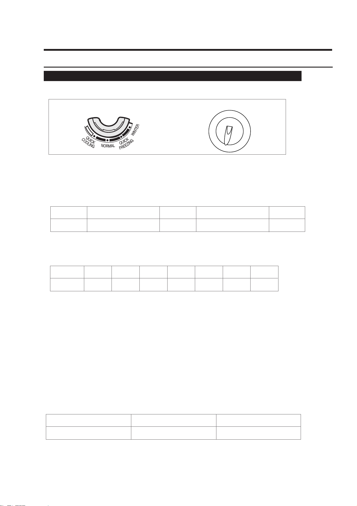
1. Temperature Control Part Design
2. Temperature Control Function
1)Selecting Freezer Temperature
l
Selecting “Quick cooling~Quick freezing”is possible with turning temperature control knob.
l
Controlled temperature of each temperature control knob position is as follows:
Knob Position
Controlled
Temperature
-15±1
Normal
-19.0
-21±1 -23±1
2)Selecting Refrigerator Temperature
l
Selecting ① ~ ⑧ is possible with turning temperature control knob.
l
Controled temperature of each temperature control knob position is as follows:
3. Defrosting Function
1)Defrosting is decided by the accumulated time of comp on.
2)Defrosting proceeds in order of heating → recess time.
3)The first defrosting function after the initial power on starts with 4 hours of accumulated
time of comp on, and then it repeats its function at every 8th hour of comp on.
4)In the process, controlling of defrosting heater ON/OFF is done by EVA-SENSOR. When the
quality of EVA-SENSOR is poor (short/open) defrosting will be terminated only after recess
time function without heating.
5)In the process, comp and fan maintain ON condition, after defrosting heating it operates with
10 min. recess time.
6)defrosting heating point ON and OFF operates by EVA-SENSOR and each temperature is as
follows:
Caution) As this controller is by the ROTARY S/W, in case it is off the position, it is set to step 4 automatically.
Knob Position
Controlled
Temperature
①
6.0
➁
4.5
➂
3.0
➃
2.0
➄
1.0
➅
0.0
➆
-1.0
Freezer Temperature Controller
Refrigerator Temperature Controller
Heater On Point
below -5℃
Heater Off Point
15℃
Remark
Quick cooling Quick Freezing Winter

14
4. Testing Function
l
This function is for PCB and test of products, work process test, and SVC.
l
After checking the product's function by selecting TEST S/W, let the self-diagnosis function
start with the POWER OFF and ON.
1)Forced Starting Function
l
COMP and FAN starts immediately after the TEST S/W on the Main PCB is pressed once. So
when the forced staring function is done right at the COMP OFF point, Over Load in the
COMP may be caused. Extra caution is necessary.
l
When forced starting function is selected, COMP and FAN run for 24 hours regardless of the
freezer/refrigerator temperature and knob selection. Indicating Lamp on main PCB shows that
it is a forced starting function by 0.5sec interval ON/OFF.
l
When a selected forced starting function is selected and maintains for 24 hours, defrosting
function starts its operation, and when defrosting is completed normal operation is carried out
according to the temperature selection knob position.
l
To release it's operation during forced starting, power should be turned off and turned on
again or test release mode on 3) below should be selected.
2)Forced Defrosting Function
l
If test switch is pressed once more during forced starting function, it is released immediately
and forced defrosting function starts, and the Lamp on main PCB shows that it's forced
defrosting by 1.0 sec. interval ON/OFF.
l
When forced defrosting is selected COMP and FAN is turned off immediately, and defrosting
heater is turned on at the same time. At this moment if the sensed temperature of EVASENSOR is higher than -5.0℃, defrosting heater is not turned ON and operates only for recess
time and returns to normal operation.
l
When Heating is completed it recesses for 10 mints. and after that indicating Lamp remains
ON and returns to normal operation.
3)Test Function Release Mode
If TEST S/W is pressed once more when forced defrosting function is carried out, forced
defrosting is released and stops for 10 mints. and after that it returns to normal operation.